Article

Influence of Wide-Bandgap Semiconductors in Interleaved Converters Sizing for a Fuel-Cell Power Architecture

ESTACA, ESTACA’Lab—Paris-Saclay, F-78180 Montigny-le-Bretonneux, France
*
Author to whom correspondence should be addressed.
World Electr. Veh. J. 2024, 15(4), 148; https://doi.org/10.3390/wevj15040148
Submission received: 20 February 2024 / Revised: 15 March 2024 / Accepted: 1 April 2024 / Published: 3 April 2024

Abstract

:
This study presents a decision-support methodology to design and optimize modular Boost converters in the context of fuel-cell electric vehicles. It involves the utilization of interleaved techniques to reduce fuel-cell current ripple, enhance system efficiency, tackle issues related to weight and size concerns, and offer better flexibility and modularity within the converter. The methodology incorporates emerging technologies by wide-bandgap semiconductors, providing better efficiency and higher temperature tolerance. It employs a multiphysical approach, considering electrical, thermal, and efficiency constraints to achieve an optimal power architecture for FCHEVs. Results demonstrate the advantages of wide-bandgap semiconductor utilization in terms of volume reduction and efficiency enhancements for different power levels. Results from one of the considered power levels highlight the feasibility of certain architectures through the utilization of WBG devices. These architectures reveal improvements in both efficiency and volume reduction as a result of incorporating WBG devices. Additionally, the analysis presents a comparison of manufacturing cost between standard and wide-bandgap semiconductors to demonstrate the market penetration potential.

1. Introduction

With the increasing demand for transporting people or equipment, the transport sector is continuously evolving, necessitating the development of diverse modes of conveyance. On the other hand, the impact of energy cost has precipitated a transition from obsolete, petroleum-based fuel into electric vehicles [1,2,3,4,5]. Indeed, the transport sector is responsible for around 25% of the final energy consumption in the world and continues to grow [6,7], with the major amount of energy produced from fossil sources, respectively, oil, coal, and natural gas. This perspective shift involves a transitional phase characterized by innovative approaches to electrifying these vehicles, such as full-electric vehicles (EVs), plug-in hybrid electric vehicles (PHEVs), and hybrid electric vehicles (HEVs) [8]. They benefit from several advantages, such as quiet operation, regenerative braking, and zero pollutant emissions while driving. However, EVs, PHEVs, and HEVs still suffer from charging times and driving range [9,10]. Several studies are exploring ways to meet the increasing electricity demand in terms of green production for charging electric vehicles, with initiatives such as photovoltaic parking lots or wind turbines gaining attention [11,12]. Nevertheless, it is essential to note that PHEVs and HEVs still depend on oil and cannot be named as zero pollutant emission vehicles [5]. Furthermore, these types of vehicles still face some challenges represented as energy efficiency, cost, performance, service continuity, modularity, etc.
The prospect of utilizing dihydrogen as the primary power source for vehicles stands out as one of the promising solutions to address the existing limitations [4,13]. Although hydrogen production faces challenges, particularly with methods like steam methane reforming process (SMR) that emit pollutants, renewable energy sources like solar panels and wind turbines offer alternative methods for producing hydrogen using excess power [14,15,16]. Unfortunately, at present, almost all hydrogen production comes from this polluting process. In the long term, this green approach could remain beneficial for local hydrogen production, moderating challenges associated with hydrogen transportation.
The Fuel-Cell Hybrid Electric Vehicle (FCHEV) hence represents an innovative concept, combining a fuel cell with an energy-storage system (ESS) to provide the propulsion power requirement. The ESS can be either a battery pack or an ultracapacitor pack. The battery remains more suited for automotive applications. This hybridization ensures a more flexible and efficient propulsion system, offering potential solutions to overcome the challenges associated with conventional electric vehicles, particularly in terms of autonomy, refueling infrastructure, interaction with renewable energies, and overall performance [17]. The literature also supports similar conclusions [18], considering the level of vehicle autonomy.
This transition to electrifying vehicles leads to a significant rise in the demand for power electronics converters. These converters play a major role in the conversion process of EVs, facilitating the adaptation of electric requirements between sources and the propulsion system while preventing the risk of premature source degradation.
Within the automotive sector, power electronics find various applications in extremely harsh environments. They need to comply with the tendency to use less and less volume and weight, as well as ensure service continuity within the power architecture. These considerations are inherently linked to powertrain efficiency, which, similarly, influences fuel consumption reduction [19]. In this challenging context, these components are subjected to operation under elevated temperatures, necessitating a delicate balance between reliability and cost-effectiveness. The imperative is to ensure that power electronics in automotive applications not only meet precise performance standards but also remain economically viable within the absolute objectives of enhancing powertrain efficiency and reducing energy consumption. This involves the use of appropriate converter architectures and the associated components.
Indeed, among the proposed solutions, the interleaving technique is introduced to limit constraints related to components and improve overall converter efficiency by incorporating parallel commutation cells within the converter. Interleaved converters represent a notable advancement in power electronics, addressing key challenges associated with conventional converter architectures. This innovative approach offers several advantages, with a primary focus on minimizing the stresses on individual components by distributing the current load among multiple cells, mitigating issues related to current ripples and associated constraints. Another benefit is the enhanced efficiency of the converter, which reduces losses and optimizes energy transfer. Furthermore, interleaving contributes to the compactness and modularity of power electronics systems, allowing for more flexibility and adaptability in various applications. This modularity not only simplifies system design but also enhances service continuity and fault tolerance, key factors in the evolving landscape of electric vehicles and renewable energy systems.
In another way, the present Silicon (Si) power electronics technology is reaching the theoretical limits of the material [20], making it less performant to meet all the requirements of power electronics within the transportation industry. The maximum junction temperature limit of Si is approximately 150 °C, necessitating substantial heat sinks to fulfill all the vehicle specifications. Furthermore, the switching frequency of Si-based devices is constrained due to the heat generated, primarily caused by the switching losses. Fortunately, a new class of semiconductor materials, known as wide-bandgap (WBG) semiconductors, stands to surpass current materials in transportation applications. Among these materials are silicon carbide (SiC), gallium nitride (GaN), and diamond [21].
This work pursues a previous study [22], aiming to design a FCHEV with interleaved converters using an optimization algorithm. The objective is to develop an efficient sizing methodology, incorporating the modularity concept through the utilization of an interleaved architecture combined with the use of the potential of wide-bandgap semiconductors.
The article is organized as follows: the first section provides an overview of current technologies and challenges in the field. In the second section, the designed approach is detailed, emphasizing the innovative aspects of the interleaved converter design. The third section presents results and analysis, providing an understanding of the performance and efficiency gains of the proposed design and the potential of wide-bandgap semiconductors. A brief conclusion underlines, however, some limitations and the future of this work.

2. Literature Review

Despite facing certain limitations, FCHEVs share the inherent benefits of EVs, making them a promising solution for the future of mobility [8,23]. The Proton Exchange Membrane Fuel Cell (PEMFC) emerges as the most viable fuel-cell technology for transportation applications due to its low operating temperature, high power density, and quick start-up.
Various architectures are available for constructing FCHEVs, primarily differing in the chosen power sources. These architectures involve the hybridization of a fuel cell with batteries, ultracapacitors, solar panels, or a combination of those. Additionally, distinctions exist based on the presence of a DC converter between the power source and the DC bus. Some manufacturers prefer individual DC converters for each power source, while others encourage the incorporation of a single DC converter for the battery or fuel cell only [24].
Considering the intrinsic features of PEMFCs, characterized by slow dynamic response, low voltage, and high current, and taking into account the voltage specifications of the motor drive system, it is imperative to incorporate a power converter between the PEMFC and the motor drive system. This is crucial for achieving effective power conditioning.
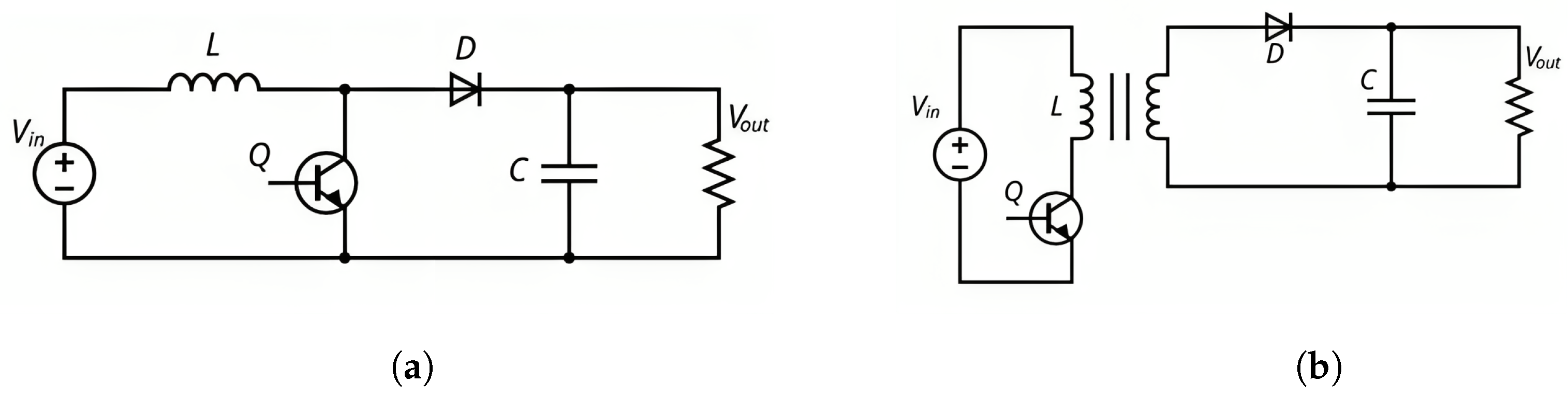
There are two different kinds of DC/DC converters, isolated and non-isolated, which are presented in Figure 1. Isolated converters settle on galvanic isolation, but this advantage comes at the expense of increased volume, higher weight, and multiplied complexity in the design process [25].
On the other hand, non-isolated DC/DC converters are widely favored due to their simple design, high compactness, cost-effectiveness, and simplified control. Notable non-isolated topologies, such as the Boost converter, Buck converter, Buck-Boost converter, Cuk converter, and Flyback converter, are well-established in the field [26].
Among these various topologies, the Boost converter stands out as the most frequently utilized, primarily due to its inherent advantages in terms of simplicity and cost-effectiveness. It is essentially applied to non-reversible systems. The voltage gain ratio of a Boost converter consistently remains above one throughout the entire duty cycle range (from zero to one), resulting in a positive output voltage concerning the input voltage. These characteristics contribute to its prominence in various domains, particularly in fuel cell embedded systems [24].
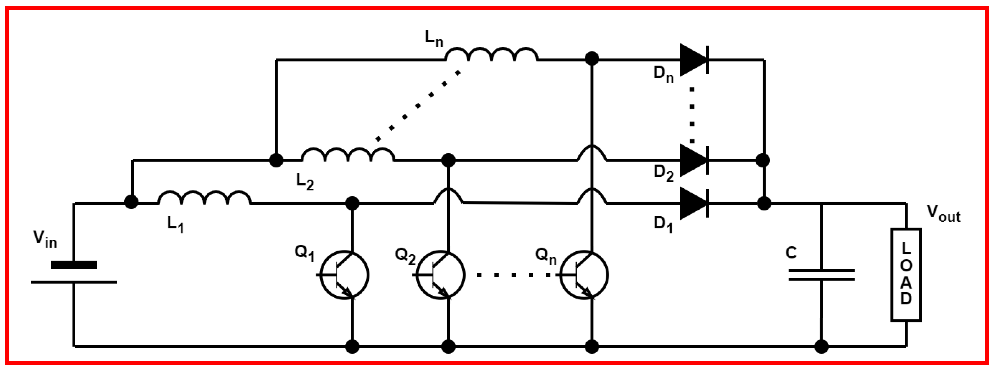
In search of supporting the main constraints for fuel cell integrating, like minimizing current ripple, increasing lifespan, and concurrently addressing concerns regarding the weight and size of the FC system, a range of non-isolated DC/DC Boost converters has been developed based on the interleaved technique. This strategic design aims to enhance the efficiency and performance of the converters by interleaving multiple switching cells, as illustrated in Figure 2. Additionally, it improves modularity, thus enhancing service continuity and fault tolerance within the converter.
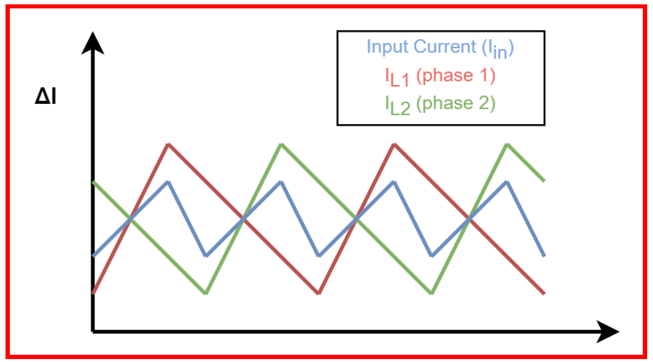
Interleaving involves distributing the input current across multiple parallel power switches, resulting in a reduction in the current stress experienced by each power switch. This, therefore, enhances the overall efficiency and performance of the converter, along with enhancing modularity and service continuity. The adoption of such configurations not only contributes to minimizing current ripple but also plays a crucial role in optimizing the overall weight and volume of the fuel-cell power architecture [27]. As shown in Figure 3, the input current ripple is reduced, therefore preserving the energy source from high current fluctuations.
The Floating Interleaved Boost Converter (FIBC) has received considerable attention in research studies [28]. This converter stands out for its capability not only to reduce power source current ripple but also to benefit from a better voltage gain ratio. Nevertheless, it is worth noting that the control design for the FIBC remains more complicated, in terms of practical realization and control, compared to the Interleaved Boost Converter (IBC) [29].
Diverse solutions have been introduced to address these challenges, incorporating innovative architectures and/or components. In particular, from an architectural perspective, a notable technique involves coupled magnetic components. This approach aims to enhance compactness, decrease weight, and amplify voltage gain within the converter system. By integrating coupled magnetic components, these converters achieve a more relevant design, enhancing the system efficiency and minimizing the impact of current ripple at the converter input but also within the individual phases [30].
From a component perspective, the emergence of wide-bandgap semiconductors has offered the possibility to design converters with significantly improved efficiency. It presents an innovative opportunity to enhance the performance of converters by exploiting the better electronic properties inherent in materials such as silicon carbide (SiC) and gallium nitride (GaN). Wide-bandgap semiconductor materials reveal exceptional electrical characteristics compared with Si, as shown in Table 1:
These new components present reduced conduction losses and switching losses, allowing for an elevated switching frequency. Additionally, they possess higher thermal conductivity, except for GaN. This results in a lower junction-to-case thermal resistance, facilitating more efficient heat transfer out of the device. Consequently, these components can operate at significantly higher temperatures, reaching up to 600 °C, in noticeable contrast to the maximum junction temperature limit of around 150 °C for Silicon devices [31]. These characteristics offer greater flexibility in the sizing process and, most importantly, in the exploration of optimization possibilities [32].

3. Implementation and Modeling

3.1. Approach Description

As this study is intended for application in a hybrid power architecture using a fuel cell as the primary source, the focus is directed toward the power chain composed of the fuel cell, the power converter, and the load, illustrated in the upper section of Figure 4. The load is represented as a power demand deducted from the maximum power needed for a small city car driving through a WLTC driving cycle.
The pre-sizing methodology, presented in Figure 5, involves an optimization process with multiphysical constraints. It follows the same progression as a previous study, [22], including the use of the Particle Swarm Optimization (PSO) algorithm for its flexibility-making ability to optimize key sizing parameters.
PSO is an optimization algorithm inspired by the social behavior of bee swarms or fish schooling, as illustrated in Figure 6. In PSO, a population of potential solutions, called particles, traverses the search space, seeking the optimal solution. Initially, particles are randomly placed within the space, and their fitness is evaluated based on a predefined objective function. Then, each particle updates its velocity and position guided by its previous movement, its personal best solution, and the best solution found by any particle in the population. This continuous adjustment allows particles to explore promising regions in the search space efficiently. The best solutions for personal and global use have been updated accordingly. Through iterative refinement, particles converge towards the optimal solution. PSO terminates when a predefined stopping criterion is met. Overall, PSO effectively balances exploration and exploitation to find optimal solutions for continuous optimization problems.
The key sizing parameters are submitted to an objective function for minimization purposes. The search region will vary depending on whether WBG or Si devices are employed within the converter. At each iteration, physical constraints are evaluated and incorporated into the cost function as penalties. If a constraint is violated, it contributes to the cost of the objective function, leading to the exclusion of that particular solution.
Several performance indexes can be considered in the cost function, including overall volume, component lifespan, and efficiency, among others. It is important to note that the cell number can be considered to be either a key sizing parameter or an input specification, allowing for the analysis of a specific architecture. In this context, the first phase of our methodology considers the global volume of the system as an objective function, as it remains a significant industrial challenge in FCHEV development. The article will focus on detailing the diverse constraints linked to the cost function, including electrical, thermal, and efficiency aspects. This exploration will adhere to the specified formalism outlined in Table 2.

3.2. Modeling

The global optimization methodology is described in Figure 7 and illustrates the different parts of this optimization process.
The approach is composed of:
  • The vector of optimization parameters, containing the parameters to be optimized, which the algorithm can manipulate to achieve the desired objective and respect the imposed constraints, resulting in an optimal architecture.
  • The specifications, setting out all the constraints to be satisfied for pre-sizing, as well as the requirements from the load.
  • The behavior modeling, representing the proper functioning of both systems, fuel cell and DC/DC converter.
  • The optimization algorithm, seeking optimal solutions and corresponding parameter values to attain a better objective while respecting the imposed constraints.
As a reminder, the following modeling equations recapitulate those used in a previous article. Therefore, these equations will be presented without a detailed explanation.

3.2.1. Components Volume

The overall volume encompasses the fuel-cell volume and the converter volume, including the inductance, capacitor, and heat-sink volume. The fuel-cell volume is determined through a trend curve established by comparing various fuel-cell systems’ volumes with different power levels within the industry. Volume equations for the inductor and capacitor are adapted from [33], relating volumes proportionally to their stored energy. The heat-sink volume is calculated using a formula from [34], with parameters derived from a compromise across several catalogs of industrial heat sinks. They are represented as follows:
Fuel-Cell volume:
V o l F C = 1.5625 · 10 3 P F C m a x
Inductance volume:
V o l L = k L 1 · L · I L m o y 2 + k L 2 · L + k L 3 · I L m o y
Capacitor volume:
V o l C = k C 1 · C · V C 2 + k C 2
Heat-sink volume:
V o l R a d = C 1 · R t h R a d ( C 2 )
where P F C m a x is the FC max power, k L is a constant factor describing the correlation between stored energy and coil volume, L is the inductance value, I L m o y is the average current flowing through the inductance, k C 1 describes the connection between the capacitor volume and stored energy, while k C 2 is a voltage-dependent factor, C represents the capacitance value and V C the voltage across the capacitor, R t h R a d is the heat-sink thermal resistance and C 1 and C 2 are coefficients extracted from manufacturers’ data.

3.2.2. Multiphysical Constraints

Electrical Constraints

The electrical constraints chosen are the current/voltage ripples, described as:
Inductance current ripple:
Δ I L = V o u t ( 1 α ) α L f
Output voltage ripple:
Δ V o u t = I o u t α C f
Input current ripple:
Δ I i n = α · 1 q α V o u t L f
where V o u t is the voltage at the converter’s output, α is the duty cycle, L is the inductance value, f is the commutation frequency for one cell, C is the capacitor value, I o u t is the output current of the converter, and q is the number of cells. It is important to notice that (7) is only applicable for ( 1 / q ) < α (no overlapping is considered).

Efficiency

The converter efficiency is estimated as the ratio between the output power and the input power of the converter. It is then computed using the following model:
η = P S P S + Σ l o s s e s = P S P S + q · ( P s w i t c h + P L ) + P C
where P S represents the output power, q the number of switching cells, P s w i t c h the power losses of the two switches, P L the losses associated with the inductance and P C the losses of the capacitor.

Thermal

The thermal modeling is illustrated by a set of thermal resistances characterizing each part of the component, as represented in Figure 8 and assuming a shared heat sink. The junction temperatures of the switch and diode ( T j s w and T j d ) are estimated for an elementary cell. This model incorporates switch and diode losses ( P s w and P d ) as heat sources. Thermal resistances (junction case: R t h j c s w and R t h j c d ; case sink: R t h c s s w and R t h c s d ; sink air: R t h s a ) are employed to simulate the thermal exchanges between the semiconductor junction and its case, between the case and the heat sink, and between the heat sink and the environment.
T j _ s w = T a + ( R t h j c _ s w + R t h c s _ s w ) P s w + q · R t h s a ( P s w + P d )
For the diode:
T j _ d = T a + ( R t h j c _ d + R t h c s _ d ) P d + q · R t h s a ( P s w + P d )

4. Results and Analysis

The chosen architecture follows the previous indications, as illustrated in Figure 4. It involves a fuel cell paired with a DC Boost converter connected to a load. This architecture is part of a fuel-cell hybrid electric vehicle comprising two power chains operating in parallel. The hybridization concept provides high degrees of freedom for optimal sizing and associated energy management, as explained in [35]. The fuel cell adopted is a Ballard PEMFC type.
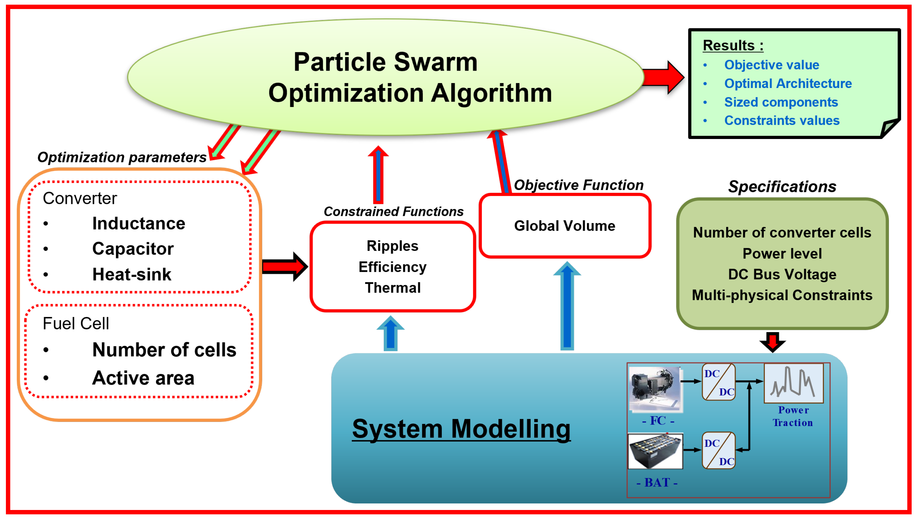
The methodology was executed within the MATLAB R2020b environment, and the optimization algorithm was self-coded to provide adaptability in parameter adjustments.
The primary optimization parameters for the power converter include the cell number (q), which plays a central role in defining the converter architecture, switching frequency (f), elementary cell inductance (L), and output capacitance (C). Technology parameters for each component are also included as optimization parameters due to the substantial influence of passive component technology on both constraints and the objective function. Considering the energy sources, the optimization process for the fuel cell integrates the number of cells arranged in series and the active surface area of each cell as primary parameters. Consequently, the optimization process aims to minimize the performance indexes (objective function) according to the constraints/requirements considered by evaluating their optimal range values.

4.1. Optimization Results

4.1.1. Laboratory Use Case

First, to assess the impact of wide-bandgap technology integration in a fuel-cell electric vehicle, an interleaved converter within a power chain that incorporates a fuel cell connected to a small load is considered, with the following specifications:
  • Output DC bus voltage: 60 V
  • Output Load power: 2 kW
  • Cell number: 1 , 2 , 3 , 4
Moreover, the associated problem formulation is exposed in Table 3:
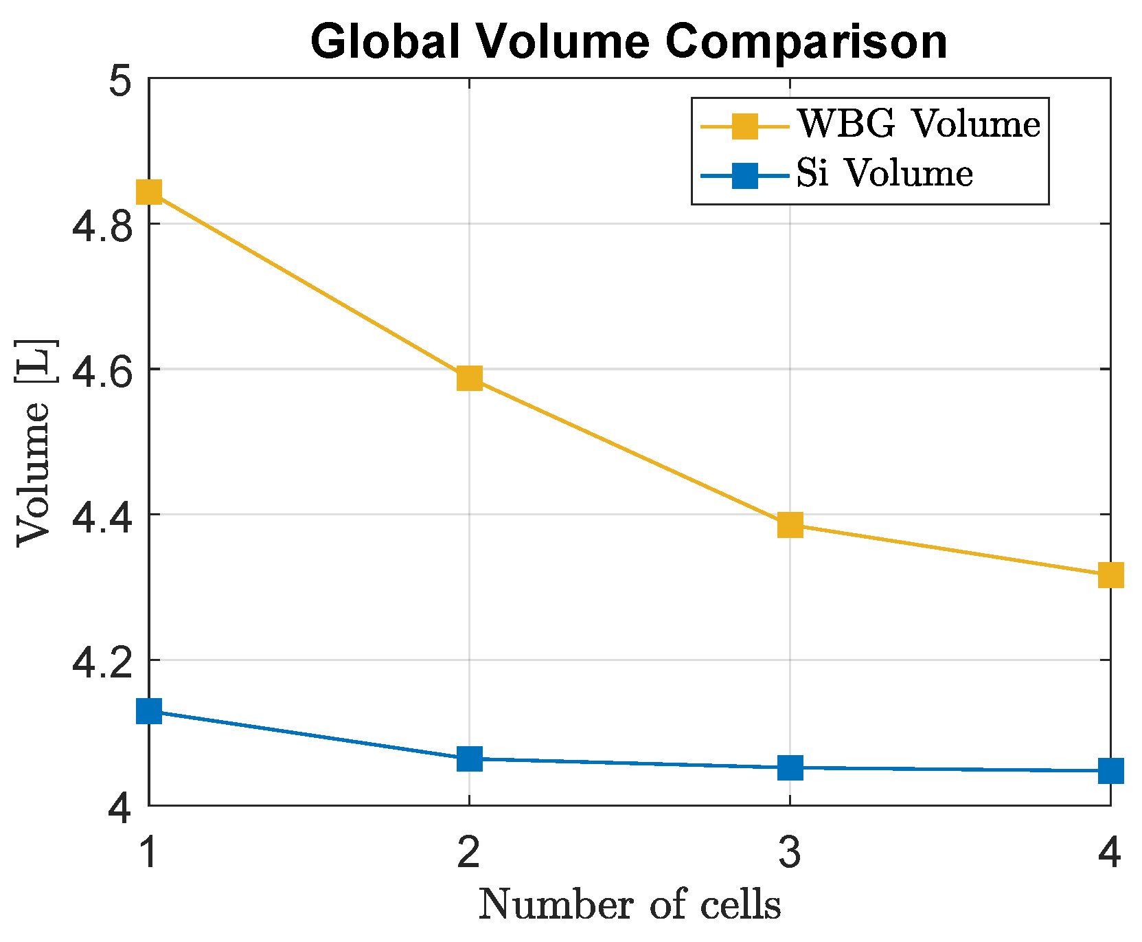
The initial validation focuses on a laboratory use case with a small 2 kW load operating at a 60 V voltage level. This preliminary step provides an initial analysis of the benefits of using wide-bandgap devices. As illustrated in Figure 9, when operating with a single-cell DC/DC converter, the utilization of WBG devices reduces the optimal architecture volume by 12.5%. However, this reduction is less pronounced when working with an interleaved converter. This observation underscores the impact of WBG devices in different converter configurations, highlighting the need for further exploration and optimization in specific scenarios.
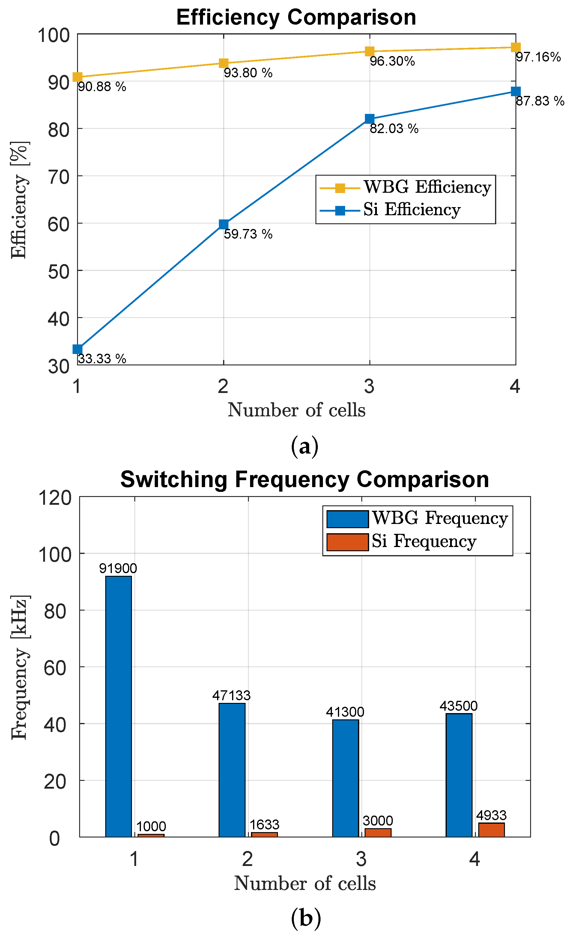
On the other hand, Figure 10a illustrates the efficiency comparison of each architecture. It is important to note that the converter efficiency for each architecture using wide-bandgap devices outperforms that of architectures employing standard (Si) devices.
Indeed, at this power level, the algorithm can explore among very high switching frequencies, as demonstrated in Figure 10b (around 100 kHz), because wide-bandgap devices can tolerate much higher junction temperatures (600 °C) than standard devices. It is worth noting that an increase in the switching frequency provokes a higher junction temperature in semiconductor devices due to the rise in power losses in the components. This, consequently, results in a better converter efficiency and enhances the current/voltage ripples on the converter input/output, as shown in Table 4.
On the contrary, for architectures using standard devices, the upper limit of component junction temperature is reached much more quickly (130 °C), forcing the algorithm to search for larger elements to accommodate the imposed ripples. Consequently, this leads to a larger overall architecture volume with significantly lower switching frequencies.

4.1.2. Real-Car Use Case

The transition from a small 2 kW load to a significant 40 kW use case marks an evolution from laboratory-scale simulations to a more representative scenario aligning with automotive applications. This progression aims to analyze the adaptability and performance of the proposed WBG devices and interleaved converter architecture in a context that reflects the power demands of actual vehicles. The outcome of this new study will provide valuable insights into the feasibility and advantages of implementing WBG devices in power converters for electric vehicles, emphasizing their potential impact on larger-scale applications. Consequently, the updated requirements are as follows:
  • Output DC bus voltage: 360 V
  • Output Load power: 40 kW
  • Cell number: 1 , 2 , 3 , 4
These specifications are selected based on the maximum power delivered by the fuel cell within a WLTC-driven cycle. Employing the same formalism as stated in Table 3, the new use case presents different results compared to the initial validation.
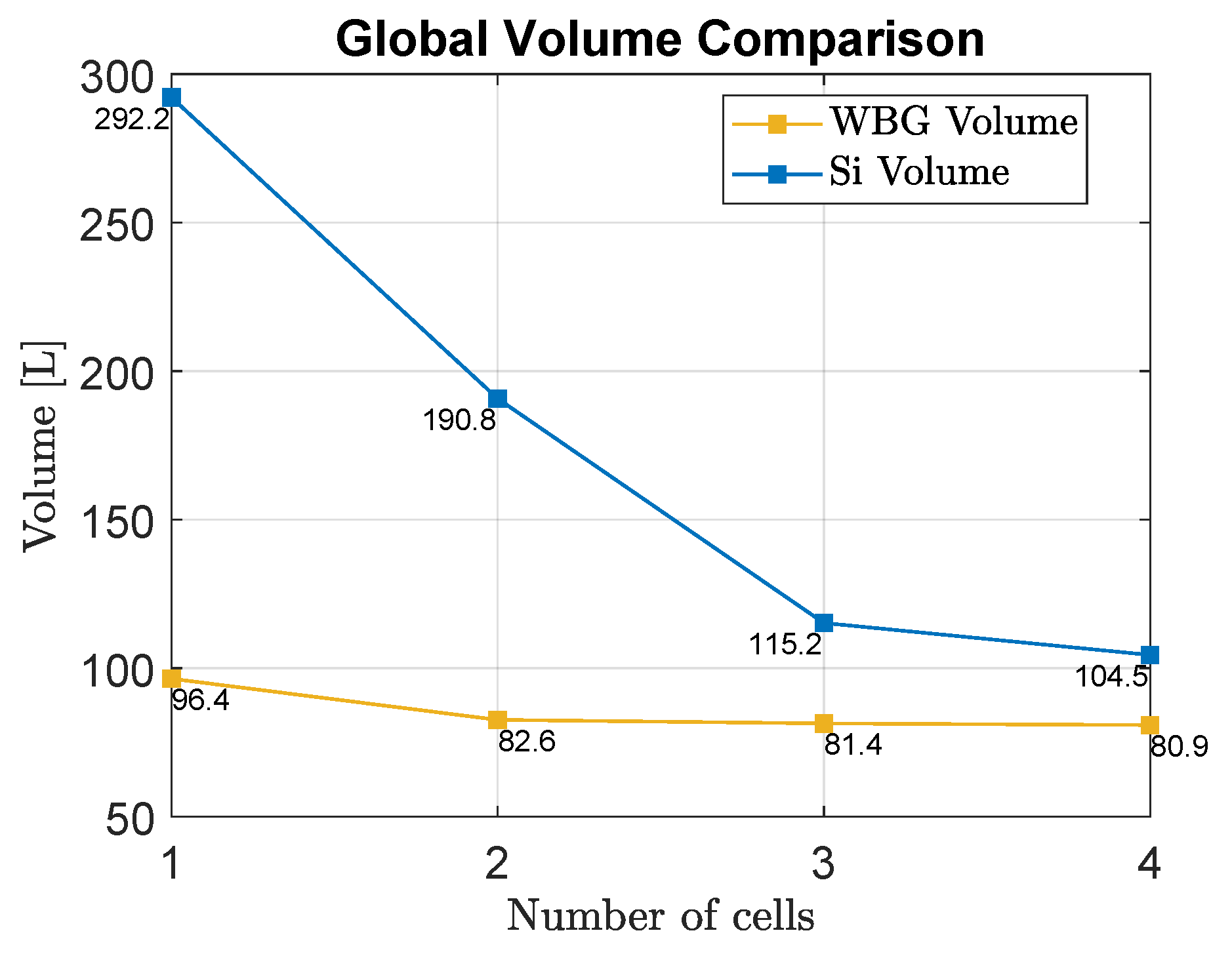
As indicated in Figure 11, the volume gain in this scenario is notably significant, with a remarkable 22% reduction achieved using a four-phase interleaved converter.
Regarding the architecture utilizing Si devices with only one switching cell, it is crucial to highlight that the semiconductor junction temperatures serve as the limiting factor. Consequently, the algorithm tends to prioritize lower switching frequencies, leading to increased input and output ripples and a reduction in the converter’s efficiency, as illustrated in Figure 12.
Moreover, this approach pushes the fuel-cell voltage to its maximum to restrict the current flowing through the converter. However, this configuration remains not feasible according to the previous formalism described in Table 3. The demand for current exceeds the limits achievable using Si devices. To align with the formalism, the two revised limits are presented in Table 5:
A similar issue occurs when employing a two-phase converter, as indicated in Table 6. However, the architecture becomes feasible when utilizing a 3-phase or 4-phase interleaved converter.
In contrast, in the absence of interleaving, the limiting constraint for the WBG architecture is the input current ripple. Consequently, the algorithm tends to favor higher switching frequencies, which have a reduced impact on these advanced semiconductors capable of supporting elevated junction temperatures.
When interleaving phases, the algorithm makes a compromise between current/voltage ripples and semiconductor temperatures.
It is noteworthy that, despite these considerations, the converter efficiency remains significantly higher when utilizing WBG devices.
Finally, the demonstrated performances of wide-bandgap devices open up new possibilities for maximizing the modularity potential of the converter in terms of both efficiency and service continuity. The improved capabilities of these innovative devices, particularly in handling power flow, contribute to excellent performance and introduce new solutions for system reconfiguration in the event of faults within the converter.
These findings rather align with existing literature, as seen in [36,37], which indicates that the use of WBG devices increases inverter efficiency. However, compared with other studies [38,39], the results obtained here are less optimistic in terms of volume reduction. Nevertheless, all these studies prove a notable enhancement in converter efficiency, attributed to the capability of WBG devices to operate at much higher switching frequencies and junction temperatures.

4.2. Cost Analysis

While the adoption of wide-bandgap devices presents significant advantages, particularly in achieving a noticeable reduction in volume, it is essential to reveal that these advanced devices come with a higher associated cost. The trade-off between the gains in volume efficiency and the increased expenses incurred by the utilization of WBG devices is an important consideration in the overall evaluation of the power converter architecture for fuel-cell electric vehicles. This balance between performance benefits and economic considerations underscores the need for a comprehensive analysis and optimization process in the design of power converters for real-world applications.
Even if WBG devices offer very useful properties in volume reduction, a challenge for the coming years remains in the cost reduction of these new components. 
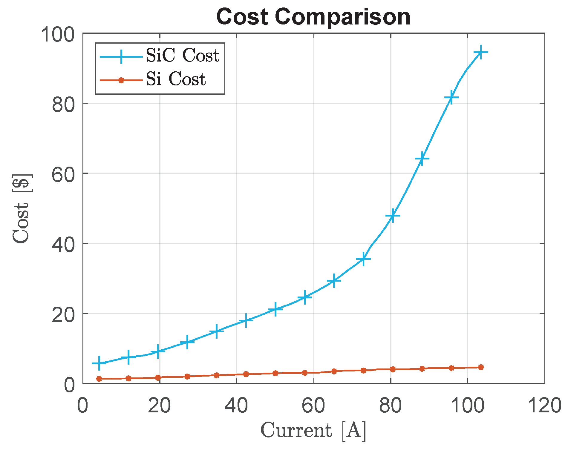
Figure 13 illustrates a succinct comparative analysis between a silicon carbide device, denoting a wide-bandgap material-based device, and a standard silicon device as a function of the current flowing through the device based on [40]. Each data point within the plot corresponds to an individual discrete device.
In a context of a 20-ampere current flow, it is noteworthy that a Si device is substantially more economical, with a cost of merely 1.5 USD, in stark contrast to the 9-dollar expense associated with the WBG device for the identical current intensity. This cost differential becomes increasingly pronounced when processing with progressively higher current levels. For instance, at an 80-ampere current, a Si device can be procured for a mere 4 USD, while the SiC device commands a significantly higher price tag of nearly 50 USD, exceeding the former by a factor superior to ten-fold.

5. Conclusions

This paper introduces a pre-sizing approach adapted for a fuel-cell electric vehicle system employing interleaved converters. The utilization of interleaved techniques, particularly with wide-bandgap semiconductors, has been investigated, showing noticeable benefits in terms of volume reduction and efficiency enhancement. The presented pre-sizing approach, using a Particle Swarm Optimization algorithm, becomes a helpful tool for designers, providing optimal power structure sizing while respecting rude specifications. Analytical models are employed to represent the system’s behavior, including sources, converters, and associated constraints (volume, electric, thermal, and efficiency). These models are subject to the number of switching cells, a crucial modular design parameter.
The results regarding a low power level reveal a notable reduction in volume, particularly noticeable in a single-cell converter but still significant in a four-cell interleaved converter. Additionally, the use of WBG semiconductors, due to their high-temperature tolerance, allows better flexibility in handling certain constraints, enhancing the converter efficiency and a higher switching frequency.
At a real-life power level based on the WLTC cycle, a 22% reduction in volume is achieved by employing a four-phase interleaved converter. Furthermore, using WBG semiconductors in this scenario enables the viability of architectures using a small number of converter cells. As in the previous case, WBG utilization improves converter efficiency and allows a moderate switching frequency, in contrast to the limited switching frequency observed in architectures employing standard semiconductors.
Moreover, the study indicated a comparison of manufacturing costs between standard and WBG semiconductors, providing an economic aspect of adopting advanced semiconductor technologies in Boost converters for FCHEVs.
There are certain limitations associated with this study. A mono-objective optimization may not fully address all aspects of system performance, but a multi-objective optimization approach could be employed to identify compromises among various performance indexes, such as power efficiency and component lifespan. This would enable the selection of the most suitable design solution based on the designer’s preferences. Furthermore, this work focuses on a single-source power chain designed for a future hybrid architecture representing an FCHEV. Subsequent studies will need to incorporate these results and approach into a hybrid power chain to better align with a real FCHEV.

Author Contributions

Conceptualization, V.M., A.C., T.A. and C.L.; methodology, V.M., A.C. and T.A.; software, V.M. and A.C.; validation, V.M. and A.C.; writing—original draft preparation, V.M.; writing—review and editing, V.M., A.C. and T.A.; supervision, T.A. and C.L. All authors have read and agreed to the published version of the manuscript.

Funding

This research received no external funding.

Data Availability Statement

The original contributions presented in the study are included in the article, further inquiries can be directed to the corresponding author.

Conflicts of Interest

The authors declare no conflict of interest.

Abbreviations

The following abbreviations are used in this manuscript:
EVElectric Vehicle
PHEVPlug-in Hybrid Electric Vehicles
HEVHybrid Electric Vehicle
SMRSteam Methane Reforming
FCHEVFuel-Cell Hybrid Electric Vehicle
ESSEnergy-Storage System
SiSilicon
WBGWide-Bandgap
SiCSilicon Carbide
GaNGallium Nitride
PEMFCProton Exchange Membrane Fuel Cell
DCDirect Current
FIBCFloating Interleaved Boost Converter
IBCInterleaved Boost Converter
WLTCWorldwide Harmonized Light Vehicles Test Cycles
PSOParticle Swarm Optimization
RMSRoot Mean Square
CCMContinuous Conduction Mode
DCMDiscontinuous Conduction Mode

References

  1. Ogunbode, C.A.; Doran, R.; Böhm, G. Exposure to the IPCC special report on 1.5 C global warming is linked to perceived threat and increased concern about climate change. Clim. Chang. 2020, 158, 361–375. [Google Scholar] [CrossRef]
  2. Qian, S.; Li, L. A Comparison of Well-to-Wheels Energy Use and Emissions of Hydrogen Fuel Cell, Electric, LNG, and Diesel-Powered Logistics Vehicles in China. Energies 2023, 16, 5101. [Google Scholar] [CrossRef]
  3. Liu, X.; Reddi, K.; Elgowainy, A.; Lohse-Busch, H.; Wang, M.; Rustagi, N. Comparison of well-to-wheels energy use and emissions of a hydrogen fuel cell electric vehicle relative to a conventional gasoline-powered internal combustion engine vehicle. Int. J. Hydrogen Energy 2020, 45, 972–983. [Google Scholar] [CrossRef]
  4. Rato, V.M.F.d.O.M. The future of the automotive industry: How will energy transition unfold in Europe? Ph.D. Thesis, Universidade Católica Portuguesa, Lisboa, Portugal, 2023. [Google Scholar]
  5. Ding, N.; Prasad, K.; Lie, T.T. The electric vehicle: A review. Int. J. Electr. Hybrid Veh. 2017, 9, 49–66. [Google Scholar] [CrossRef]
  6. Statistics-Eurostat, E. Energy, Transport and Environment Statistics, 2020th ed.; Eurostat: Luxembourg, 2020.
  7. Moriarty, P.; Honnery, D. Global transport energy consumption. In Alternative Energy and Shale Gas Encyclopedia; John Wiley and Sons: Hoboken, NJ, USA, 2016; pp. 651–656. [Google Scholar]
  8. Thomas, C. Fuel cell and battery electric vehicles compared. Int. J. Hydrogen Energy 2009, 34, 6005–6020. [Google Scholar] [CrossRef]
  9. De Wolf, D.; Smeers, Y. Comparison of Battery Electric Vehicles and Fuel Cell Vehicles. World Electr. Veh. J. 2023, 14, 262. [Google Scholar] [CrossRef]
  10. Leijon, J.; Boström, C. Charging electric vehicles today and in the future. World Electr. Veh. J. 2022, 13, 139. [Google Scholar] [CrossRef]
  11. Bhatti, A.R.; Salam, Z.; Aziz, M.J.B.A.; Yee, K.P.; Ashique, R.H. Electric vehicles charging using photovoltaic: Status and technological review. Renew. Sustain. Energy Rev. 2016, 54, 34–47. [Google Scholar] [CrossRef]
  12. Alkawsi, G.; Baashar, Y.; Abbas U, D.; Alkahtani, A.A.; Tiong, S.K. Review of renewable energy-based charging infrastructure for electric vehicles. Appl. Sci. 2021, 11, 3847. [Google Scholar] [CrossRef]
  13. Fakhreddine, O.; Gharbia, Y.; Derakhshandeh, J.F.; Amer, A. Challenges and Solutions of Hydrogen Fuel Cells in Transportation Systems: A Review and Prospects. World Electr. Veh. J. 2023, 14, 156. [Google Scholar] [CrossRef]
  14. Levene, J.I.; Mann, M.K.; Margolis, R.M.; Milbrandt, A. An analysis of hydrogen production from renewable electricity sources. Sol. Energy 2007, 81, 773–780. [Google Scholar] [CrossRef]
  15. Al-Buraiki, A.S.; Al-Sharafi, A. Hydrogen production via using excess electric energy of an off-grid hybrid solar/wind system based on a novel performance indicator. Energy Convers. Manag. 2022, 254, 115270. [Google Scholar] [CrossRef]
  16. Carmo, M.; Stolten, D. Energy storage using hydrogen produced from excess renewable electricity: Power to hydrogen. In Science and Engineering of Hydrogen-Based Energy Technologies; Elsevier: Amsterdam, The Netherlands, 2019; pp. 165–199. [Google Scholar]
  17. Pan, G.; Bai, Y.; Song, H.; Qu, Y.; Wang, Y.; Wang, X. Hydrogen Fuel Cell Power System—Development Perspectives for Hybrid Topologies. Energies 2023, 16, 2680. [Google Scholar] [CrossRef]
  18. Dudziak, A.; Droździel, P.; Stoma, M.; Caban, J. Market Electrification for BEV and PHEV in Relation to the Level of Vehicle Autonomy. Energies 2022, 15, 3120. [Google Scholar] [CrossRef]
  19. Kolli, A.; Gaillard, A.; De Bernardinis, A.; Bethoux, O.; Hissel, D.; Khatir, Z. A review on DC/DC converter architectures for power fuel cell applications. Energy Convers. Manag. 2015, 105, 716–730. [Google Scholar] [CrossRef]
  20. Zhang, L.; Zheng, Z.; Lou, X. A review of WBG and Si devices hybrid applications. Chin. J. Electr. Eng. 2021, 7, 1–20. [Google Scholar] [CrossRef]
  21. Jain, H.; Rajawat, S.; Agrawal, P. Comparision of wide band gap semiconductors for power electronics applications. In Proceedings of the 2008 International Conference on Recent Advances in Microwave Theory and Applications, Jaipur, India, 21–24 November 2008; IEEE: New York, NY, USA, 2008; pp. 878–881. [Google Scholar]
  22. Mercier, V.; Ceschia, A.; Azib, T.; Larouci, C. Pre-Sizing Approach of a Fuel Cell-Battery Hybrid Power System with Interleaved Converters. Energies 2023, 16, 4068. [Google Scholar] [CrossRef]
  23. Cremades, L.V.; Canals Casals, L. Analysis of the future of mobility: The battery electric vehicle seems just a transitory alternative. Energies 2022, 15, 9149. [Google Scholar] [CrossRef]
  24. İnci, M.; Büyük, M.; Demir, M.H.; İlbey, G. A review and research on fuel cell electric vehicles: Topologies, power electronic converters, energy management methods, technical challenges, marketing and future aspects. Renew. Sustain. Energy Rev. 2021, 137, 110648. [Google Scholar] [CrossRef]
  25. Ahmed, O.; Bleijs, J. An overview of DC–DC converter topologies for fuel cell-ultracapacitor hybrid distribution system. Renew. Sustain. Energy Rev. 2015, 42, 609–626. [Google Scholar] [CrossRef]
  26. Chewale, M.A.; Wanjari, R.A.; Savakhande, V.B.; Sonawane, P.R. A review on isolated and non-isolated DC-DC converter for PV application. In Proceedings of the 2018 International Conference on Control, Power, Communication and Computing Technologies (ICCPCCT), Kannur, India, 23–24 March 2018; IEEE: New York, NY, USA, 2018; pp. 399–404. [Google Scholar]
  27. Kabalo, M.; Blunier, B.; Bouquain, D.; Miraoui, A. State-of-the-art of DC-DC converters for fuel cell vehicles. In Proceedings of the 2010 IEEE Vehicle Power and Propulsion Conference, Lille, France, 1–3 September 2010; IEEE: New York, NY, USA, 2010; pp. 1–6. [Google Scholar]
  28. Choi, S.; Agelidis, V.; Yang, J.; Coutellier, D.; Marabeas, P. Analysis, design and experimental results of a floating-output interleaved-input boost-derived DC-DC high-gain transformer-less converter. IET Power Electron. 2011, 4, 168–180. [Google Scholar] [CrossRef]
  29. Kabalo, M.; Paire, D.; Blunier, B.; Bouquain, D.; Godoy Simões, M.; Miraoui, A. Experimental evaluation of four-phase floating interleaved boost converter design and control for fuel cell applications. IET Power Electron. 2013, 6, 215–226. [Google Scholar] [CrossRef]
  30. Kascak, S.; Prazenica, M.; Jarabicova, M.; Paskala, M. Interleaved DC/DC boost converter with coupled inductors. Adv. Electr. Electron. Eng. 2018, 16, 147–154. [Google Scholar] [CrossRef]
  31. Tolbert, L.; Ozpineci, B.; Islam, S.; Chinthavali, M. Comparison of Wide Bandgap Semiconductors for Power Applications. In Proceedings of the 10th European Conference on Power Electronics and Applications (EPE 2003), Toulouse, France, 2–4 September 2003; Volume 3, p. 7. [Google Scholar]
  32. Ballestín-Fuertes, J.; Muñoz-Cruzado-Alba, J.; Sanz-Osorio, J.F.; Laporta-Puyal, E. Role of wide bandgap materials in power electronics for smart grids applications. Electronics 2021, 10, 677. [Google Scholar] [CrossRef]
  33. Raggl, K.; Nussbaumer, T.; Kolar, J.W. Guideline for a simplified differential-mode EMI filter design. IEEE Trans. Ind. Electron. 2009, 57, 1031–1040. [Google Scholar] [CrossRef]
  34. Gurpinar, E.; Castellazzi, A. Tradeoff study of heat sink and output filter volume in a GaN HEMT based single-phase inverter. IEEE Trans. Power Electron. 2017, 33, 5226–5239. [Google Scholar] [CrossRef]
  35. Azib, T.; Bethoux, O.; Remy, G.; Marchand, C.; Berthelot, É. An innovative control strategy of a single converter for hybrid fuel cell/supercapacitor power source. IEEE Trans. Ind. Electron. 2010, 57, 4024–4031. [Google Scholar] [CrossRef]
  36. Kizilyalli, I.C.; Xu, Y.A.; Carlson, E.; Manser, J.; Cunningham, D.W. Current and future directions in power electronic devices and circuits based on wide band-gap semiconductors. In Proceedings of the 2017 IEEE 5th Workshop on Wide Bandgap Power Devices and Applications (WiPDA), Albuquerque, NM, USA, 30 October–1 November 2017; IEEE: New York, NY, USA, 2017; p. 417. [Google Scholar]
  37. Wang, F.F.; Zhang, Z. Overview of silicon carbide technology: Device, converter, system, and application. CPSS Trans. Power Electron. Appl. 2016, 1, 13–32. [Google Scholar] [CrossRef]
  38. Das, S.; Marlino, L.D.; Armstrong, K.O. Wide Bandgap Semiconductor Opportunities in Power Electronics; Technical Report; Oak Ridge National Laboratory (ORNL): Oak Ridge, TN, USA, 2018.
  39. Chaudhary, O.S.; Denaï, M.; Refaat, S.S.; Pissanidis, G. Technology and Applications of Wide Bandgap Semiconductor Materials: Current State and Future Trends. Energies 2023, 16, 6689. [Google Scholar] [CrossRef]
  40. Deshpande, A.; Luo, F. Practical design considerations for a Si IGBT+ SiC MOSFET hybrid switch: Parasitic interconnect influences, cost, and current ratio optimization. IEEE Trans. Power Electron. 2018, 34, 724–737. [Google Scholar] [CrossRef]
Figure 1. Schemes representation of a non-isolated and isolated converter: (a) Non-isolated Boost converter. (b) Isolated Flyback converter.
Wevj 15 00148 g001
Figure 2. Interleaving of a n-cell Boost converter.
Wevj 15 00148 g002
Figure 3. Current ripples waveforms of a two-phase interleaved boost converter.
Wevj 15 00148 g003
Figure 4. Parallel hybrid power source architecture.
Wevj 15 00148 g004
Figure 5. A diagram of the general principle of the developed approach.
Wevj 15 00148 g005
Figure 6. Particle Swarm Optimization principle.
Wevj 15 00148 g006
Figure 7. A global optimization methodology under multiphysical constraints.
Wevj 15 00148 g007
Figure 8. Thermal modeling of two semiconductors sharing the same heat sink: (a) Thermal dissipation setup scheme. (b) Equivalent thermal circuit of the adopted thermal management.
Wevj 15 00148 g008
Figure 9. Volume comparison of WBG and standard devices for a 2-kW load.
Wevj 15 00148 g009
Figure 10. Comparison of WBG and Si devices for a 2kW load: (a) Efficiency comparison. (b) Frequency comparison.
Wevj 15 00148 g010
Figure 11. Volume comparison of WBG and standard devices for a 40-kW load.
Wevj 15 00148 g011
Figure 12. Comparison of WBG and Si devices for a 40kW load: (a) Efficiency comparison. (b) Frequency comparison.
Wevj 15 00148 g012
Figure 13. Cost comparison of WBG and standard devices.
Wevj 15 00148 g013
Table 1. Comparison of Si and WBG characteristics [31].
PropertySi6H-SiC4H-SiCGaNDiamond
Bandgap (eV)1.123.033.263.455.45
Thermal Conductivity (W/cm.K)1.54.94.91.322
Table 2. Optimization problem and model formulation.
FormalismFunction/ VariableDescription
Minimize V o l u m e A r c h i Volume of the global architecture
with respect toConverter parameters, FC parametersParameters related to the components within the converter and Fuel Cell
Subject to R i p p l e s < R i p p l e _ m a x Constraints on current/voltage ripples in the input and output of the converter
E f f i c i e n c y > η m i n Converter efficiency constraint
S e m i c o n d u c t o r t e m p e r a t u r e < T _ m a x Constraints on the junction temperatures in the semiconductors
P F C _ m i n < F C M a x P o w e r < P F C _ m a x Security constraint to proper size the Fuel Cell
Table 3. Optimization problem and model formulation with parameter values.
FormalismFunction/VariableDescription
Minimize V o l u m e A r c h i Volume of the global architecture
with respect to L , C , f , B m a x , d , n t u r n s , R t h s a , S , n c e l l s Inductance, Capacitance, Frequency, Magnetic density, wire diameter, winding number, heat-sink thermal resistance, active surface area, number of FC cells
Subject to Δ I L 10 % Input current ripple constraint
Δ I i n 50 % Inductance current ripple constraint
Δ V o u t 10 % Output voltage ripple constraint
T j _ Si 130  °CJunction temperature for a Si semiconductor constraint
T j _ WBG 600  °CJunction temperature for a WBG semiconductor constraint
η 80 % Converter efficiency constraint
V F C 0.9 × V o u t Security constraint on the maximum fuel-cell voltage
P L o a d 0.8 × P F C _ m a x 2 × P L o a d Security constraint on the maximum fuel-cell power
I i n I l _ F C Security constraint on the maximum fuel-cell current
Table 4. Comparison of a 3-cell sizing using Si and WBG semiconductors.
ConstraintsSi ArchitectureWBG Architecture
Input current ripple (%)9.281.21
Inductance ripple (%)49.6949.75
Output voltage ripple (%)9.869.83
Converter efficiency (%)91.2493.81
Diode junction temperature (°C)129.95592.00
Switch junction temperature (°C)127.22596.00
Table 5. Optimization problem formulation with new constraints.
FormalismMathematical Definition
Constraints J u n c t i o n t e m p e r a t u r e d i o d e < 190  °C
E f f i c i e n c y > 30 %
Table 6. Comparison of a 2-cell sizing using Si and WBG semiconductors.
ConstraintsSi ArchitectureWBG Architecture
Input current ripple (%)10.019.99
Inductance ripple (%)22.5338.56
Output voltage ripple (%)0.469.51
Converter efficiency (%)52.4993.32
Diode junction temperature (°C)138.25599.96
Switch junction temperature (°C)109.00589.83
Disclaimer/Publisher’s Note: The statements, opinions and data contained in all publications are solely those of the individual author(s) and contributor(s) and not of MDPI and/or the editor(s). MDPI and/or the editor(s) disclaim responsibility for any injury to people or property resulting from any ideas, methods, instructions or products referred to in the content.

