Review

Wireless Charging for Electric Vehicles: A Survey and Comprehensive Guide

by
Mohammad Rabih
1,
Maen Takruri
2,*,
Mohammad Al-Hattab
3,
Amal A. Alnuaimi
4 and
Mouza R. Bin Thaleth
4
1
Department of Electrical Engineering, College of Engineering, American University of Sharjah, Sharjah 26666, United Arab Emirates
2
Advanced Technology and Artificial Intelligence Center, American University of Ras Al Khaimah, Ras Al Khaimah 72603, United Arab Emirates
3
College of Engineering, Al Ain University, Al Ain 64141, United Arab Emirates
4
Department of Electrical, Electronics and Communications Engineering, American University of Ras Al Khaimah, Ras Al Khaimah 72603, United Arab Emirates
*
Author to whom correspondence should be addressed.
World Electr. Veh. J. 2024, 15(3), 118; https://doi.org/10.3390/wevj15030118
Submission received: 24 January 2024 / Revised: 13 March 2024 / Accepted: 15 March 2024 / Published: 19 March 2024
(This article belongs to the Topic Advanced Wireless Charging Technology)

Abstract

:
This study compiles, reviews, and discusses the relevant history, present status, and growing trends in wireless electric vehicle charging. Various reported concepts, technologies, and available literature are discussed in this paper. The literature can be divided into two main groups: those that discuss the technical aspects and those that discuss the operations and systems involved in wireless electric vehicle charging systems. There may be an overlap of discussion in some studies. However, there is no single study that combines all the relevant topics into a guide for researchers, policymakers, and government entities. With the growing interest in wireless charging in the electric vehicle industry, this study aims to promote efforts to realize wireless power transfer in electric vehicles.

1. Introduction

Due to the various environmental, socioeconomic, and political issues faced today, the continued focus on sustainable solutions has paved the way for the electrification of several industries. The automotive industry is one such sector that has enjoyed the transition to electrification while moving away from traditional practices that cause heavy pollution. As a result, electric vehicle (EV) adoption is on the rise, and a significant amount of research and development is being performed to optimize the new technologies to meet the sustainability goals set by governments and international agencies, the expectations of the public, and the challenges of the status quo.
Recently, there has been a growing interest in the prospect of wireless charging for EVs as an alternative or an aid to existing wired charging systems in use. The reason for this growing interest is that wireless charging offers several key advantages over traditional and standard wired charging solutions [1]. For instance, wired charging stations pose safety risks and health hazards such as trip hazards, electrocution, risk of fires, etc. Wireless charging can help address these health and safety concerns, as the charging station and the charging pad on the vehicle are not in contact and are physically isolated. Another drawback of wired charging solutions is the lack of flexibility in allowing the vehicle’s battery to be charged at different places. Despite the developments in wired charging technologies, this is inconvenient to EV users. Moreover, research has proposed that wireless charging solutions can be less costly compared to wired solutions as there is no requirement for the technology involved for a physical connection. Perhaps the most promising aspect of wireless charging technologies is their ability to extend the driving range of EVs. Dynamic wireless charging systems are presently the most hopeful solution to the driving range problem in EVs. However, this prospect raises new operations and infrastructure challenges that need to be considered [2].
Traditionally, wireless EV charging systems are classified according to the charging mode requirement, i.e., whether the charging takes place when the vehicle is stationary or in motion. Usually, there are two main types of charging in this classification scheme that are discussed: static (Figure 1) and dynamic (Figure 2) wireless charging. In addition to the two main types, quasi-dynamic wireless charging is sometimes regarded as the third category [2,3]. The key differences are as follows:
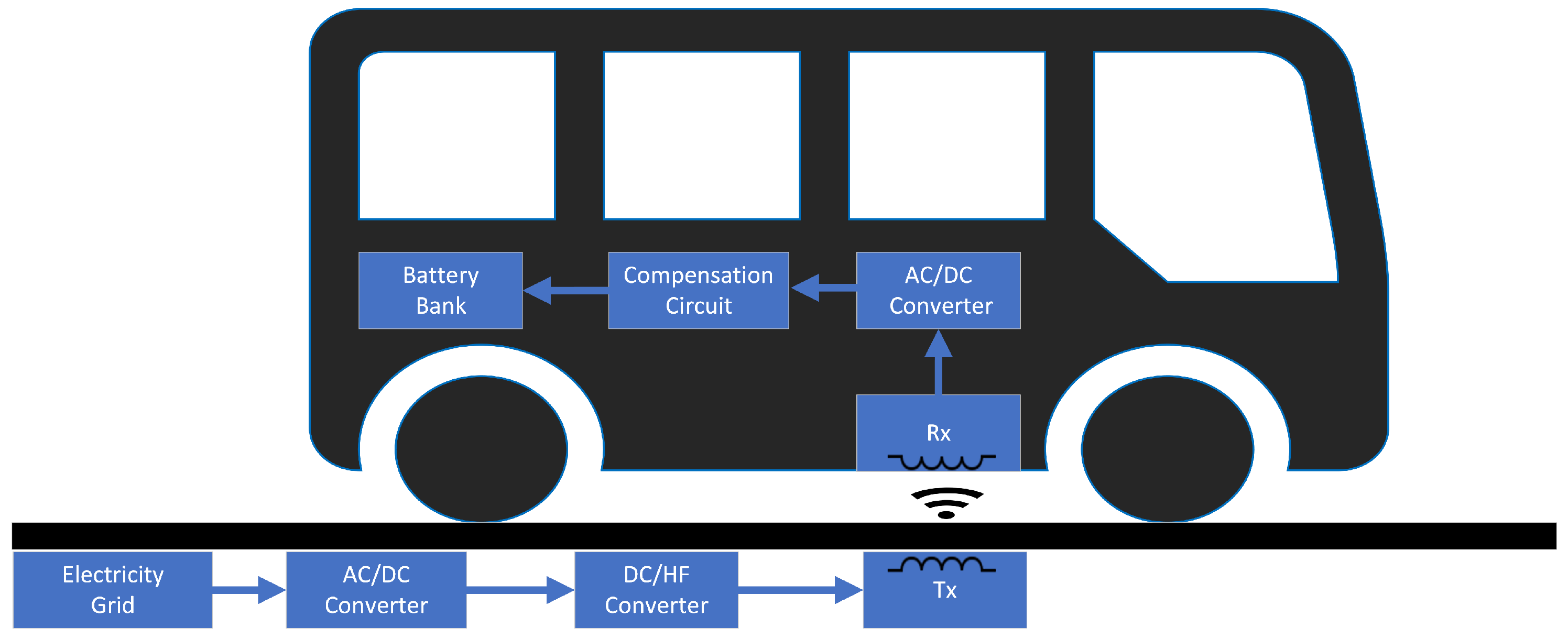
  • Static: the vehicle charges when it is stationary or parked.
  • Quasi-dynamic: the vehicle is charged as it decelerates to or accelerates from a stationary state at a low speed.
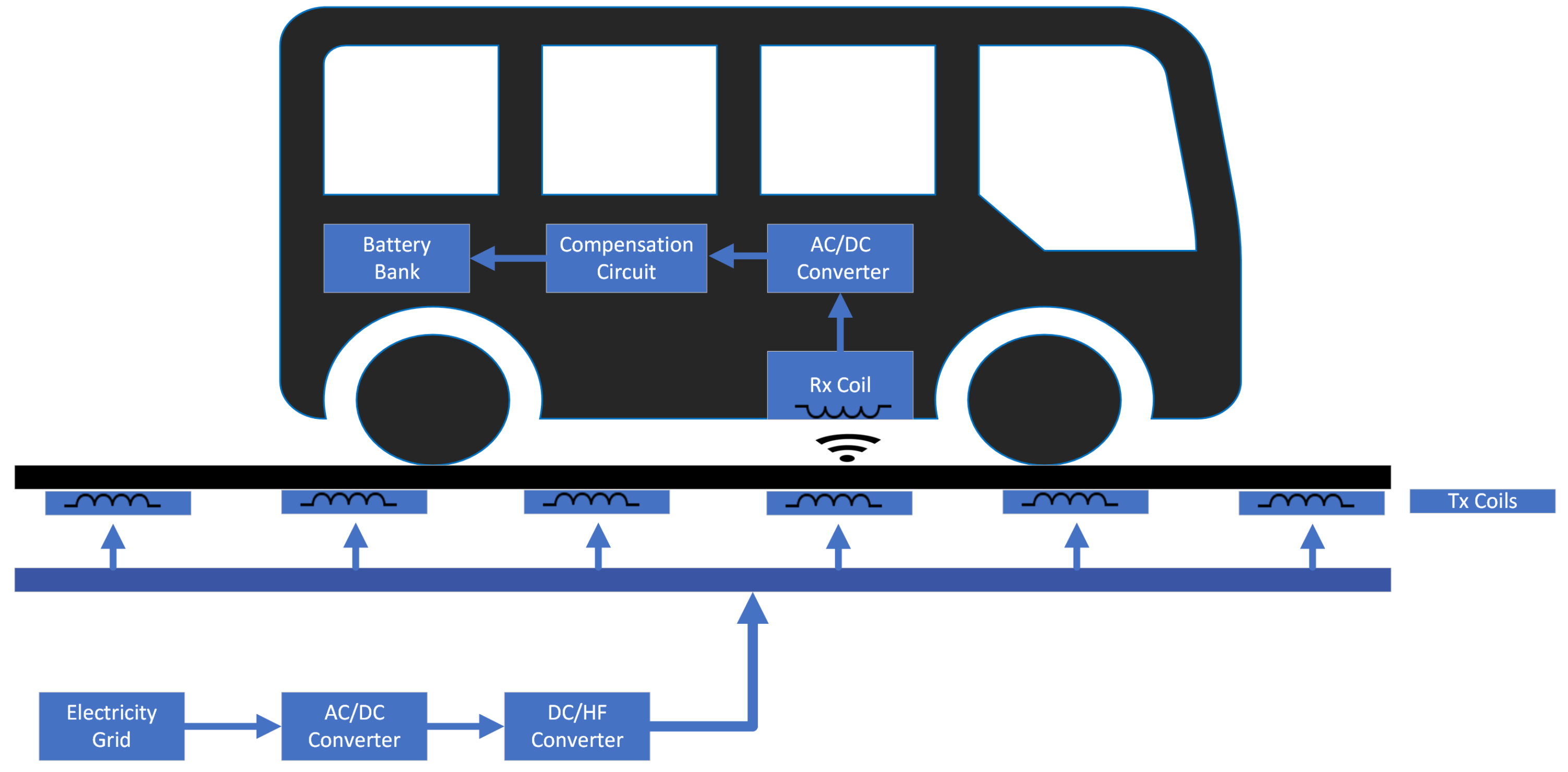
  • Dynamic: the vehicle charges while it is completely in transit.
Situations involving static charging systems are similar to those for wired charging systems in that the vehicle has to be stationed or parked. However, a benefit offered here is the ability to “park and charge” without the need to fix cables [3]. Quasi-dynamic systems can be installed at locations where the vehicle halts often, but for a limited time, before resuming its motion again. Examples of such locations may include bus stops, taxi stops, and traffic lights, where short-term charging may be performed [3]. Both quasi-dynamic and dynamic charging capabilities allow the vehicle to be charged while it is in motion. For this reason, discussions of dynamic charging often include quasi-dynamic charging.
Several aspects need to be considered and thoroughly studied to determine the desirability, viability, and feasibility of wireless charging solutions. One important aspect is determining the scale of the application. This is determining whether the wireless charging system is intended for public or private use. Secondly, the type of vehicle is also an important factor. For example, buses and public transportation would have different charging requirements than smaller private vehicles. Another aspect is determining whether to charge the vehicle either when it is parked or in motion. Researchers, engineers, planners, and policymakers need to appropriately define the context of usage and understand the purpose of application of such systems.
Due to the growing interest in the topic, there have been an increasing number of studies in the form of surveys and reviews on the different aspects of a wireless charging system for EVs. Even with the rich literature available, there are few to no studies that review the technical and non-technical characteristics of the wireless charging problem for EVs combined in one study. There are a number of reasons why a work of this nature is useful and required. Firstly, there is a high demand for such studies by government entities, policymakers, and regulators to understand the state of the art in wireless EV charging. They demand research that features feasibility studies, economic analyses, methods to analyze economic benefits, guides for pricing, infrastructure allocation models, and other planning and managerial strategies. Second, a comprehensive and detailed review of the subject will serve as an invaluable guide for academic researchers in multiple disciplines. Researchers would better understand the many dimensions of the systems, and they would also be aided in developing new research approaches. Lastly, a detailed and system-wide understanding of the topic ensures the guided progression and development of the technologies. Not only would this help in accelerating the standardization of various terms, definitions, and issues that have not been well defined in this nascent field, but it would also promote interdisciplinary progress and innovation.
The literature reviewed in this paper includes seminal works that can be considered to have significantly contributed to the efforts to realize wireless charging for EVs. Aligning with the goals set to compile a comprehensive study, well-acknowledged and frequently cited papers were reviewed first to gain insight into the trends in the literature. The observed pattern is that the research can be tentatively, but with good reason, categorized as either technical or operations research. The differences between the two categories are discussed further. Following this taxonomy, key areas in each category were determined, and the literature that discusses those areas was reviewed. Although preference was given to recent publications to highlight the trends, it can be observed that a good number of significant studies were published in the mid-to-late 2010s. In particular, works published between 1974 and 2023 have been cited in this paper, and one patent from 1894 is also cited. This strategy allowed all types of battery electric vehicles (BEVs), systems, and practices mentioned in the literature to be covered, making this study a comprehensive addition to the existing literature.
Table 1 shows a summary of the comparison between some surveys on wireless EV charging encountered in the literature and this review. Referring to the table, it can be seen that [1,4,5,6,7] focus on the technical aspects of wireless EV charging systems, while [2] is only focus on the operations and systems aspect. This review, along with [3,8], considers both aspects. However, discussions of the communication systems involved in wireless charging systems, object detection, and effects of environmental agents like snow, water, and road pollutants may not be found in [3,8]. It can also be observed that although [6] cites recent references that include those published in 2023, similar to this work, it is only focused on the technical aspects and does not cover the operational and systems perspective. Accordingly, we present this work as a complete and comprehensive guide that fills the gaps in the existing literature.
The technical reviews focus on wireless power transfer (WPT) methods, topologies for wireless charging, electric vehicle design, and hardware design, among other engineering topics. On the other hand, operations and systems research includes studies of operational strategies such as optimal allocation of the charging infrastructure, range extension, pricing and billing, construction and installation strategies, and economic analyses, among other areas of operations and systems research. Other reviews may feature either historical developments, such as [9], or the recent and current status of research into the broader topics of wireless charging for EVs, like [10,11]. It is worth noting that because the area is nascent and the literature covers a broad range of topics, many of the research works include more than one aspect for discussion. For instance, most of the work cited in this paper includes an overview of historical developments and the current status in some capacity, in addition to the authors’ informed opinions about future trends.
Thus, the aims of this study are very clear. It includes a summary of the past, the state of the present, and predictions for the future of wireless charging for EVs. The study also organizes and reviews the existing, broad literature. It provides technical and scientific exposition, like the details and comparison of the charging technologies available. Moreover, it provides the operations and systems perspective for a wider discourse. Lastly, this study serves as a complete guide for researchers, policymakers, and government entities as a reference for future work in the field of wireless EV charging.
The rest of the paper is organized as follows: Section 2 gives the necessary technical background. In particular, it introduces and details the fundamentals of WPT and its role in the context of wireless EV charging, the coil and core structure and design, a comparison of the compensation topologies, a review of the converter topologies, and a brief overview of the onboard communication systems. Section 3 addresses the current state of wireless EV charging research in the operations and systems context. It includes the research trends and other perspectives that are considered when planning for a wireless charging system. The next section discusses the status of standardization and research activities. The last section concludes the study.

2. Technical Background

The concept of WPT arises from the idea that power may be transferred from the source to the load without the need for any physical connections, such as electrical wiring. Instead, power is transferred using classical fields, such as electric, magnetic, and electromagnetic (EM) fields. Popularized by Nikola Tesla in 1914, the earliest mention of WPT dates to more than a hundred years ago [7,12]. A typical WPT system includes a power source that is connected to a transmitter and a receiver that is connected to the load. The transmitter and receiver may be coupled by electric, magnetic, or EM fields or connected by line of sight using EM waves.
Fundamentally, WPT is divided into three categories based on range and mode of transfer: near-field, medium-field, and far-field charging. Technologies incorporating near-field and medium-field charging methods are employed in existing wireless charging systems, while far-field charging technologies are expected to head wireless charging methods in the future [1,5]. Thus, they are the subject of extensive discussions among researchers. The near-field charging technologies include inductive charging (or charging by inductive coupling), magnetic-resonance charging (or coupled magnetic resonance), and capacitive charging (or charging by capacitive coupling). Similarly, a popular medium-field charging method is magnetic-gear charging. Lastly, far-field WPT includes laser, microwave, and radio wave charging technologies. The classification of WPT methods can be summarized as shown in Figure 3. More details are given for each of the aforementioned charging schemes in the following sections.
Whether the charging takes place while the vehicle is in transit or stationary, the two basic sections of a wireless charging station are the ground assembly (GA) and the vehicle assembly (VA) [13]. The GA is located underneath the ground surface and includes the power supply, which comprises a connection to the grid, a rectifier (AC–DC converter), a high-frequency inverter (DC–AC converter), a primary compensation network, and the primary/transmitter pad (Tx). The VA is comprised of the secondary/receiving pad (Rx), a secondary compensation network, a high-frequency AC–DC converter, and a filter block before feeding into the battery system [1,2,3,7]. Both of these sections of the wireless charging system generally share information via a communication link. Figure 4 shows the general architecture of the system.
At the transmission side, low-frequency AC from the grid is fed to the GA. The grid frequency is too low for power transfer; thus, the AC is converted to a higher frequency using either a single-stage or a two-stage process. Most of the time, the two-stage approach is preferred, and AC/DC/AC conversion is used, though it is possible to directly convert the grid’s low-frequency AC output to a high-frequency input to the transmitter [3,14]. In the first stage, the AC is rectified to a DC with low harmonic contents, and the power factor (PF) is corrected. Additionally, the literature makes mention of the possible usage of a Buck converter after the PF correction stage to adjust the DC power and provide soft switching capabilities. In the second stage, the DC is converted to high-frequency AC by an inverter, which is fed to the Tx. On the secondary side, the high-frequency AC is received via the Rx. It is rectified to DC, generally using a diode bridge rectifier, followed by filtration to produce a ripple-free current. In the following sub-sections, each of the WPT methods mentioned will be discussed in detail. Table 2 summarizes the essential characteristics of the discussed WPT technologies.

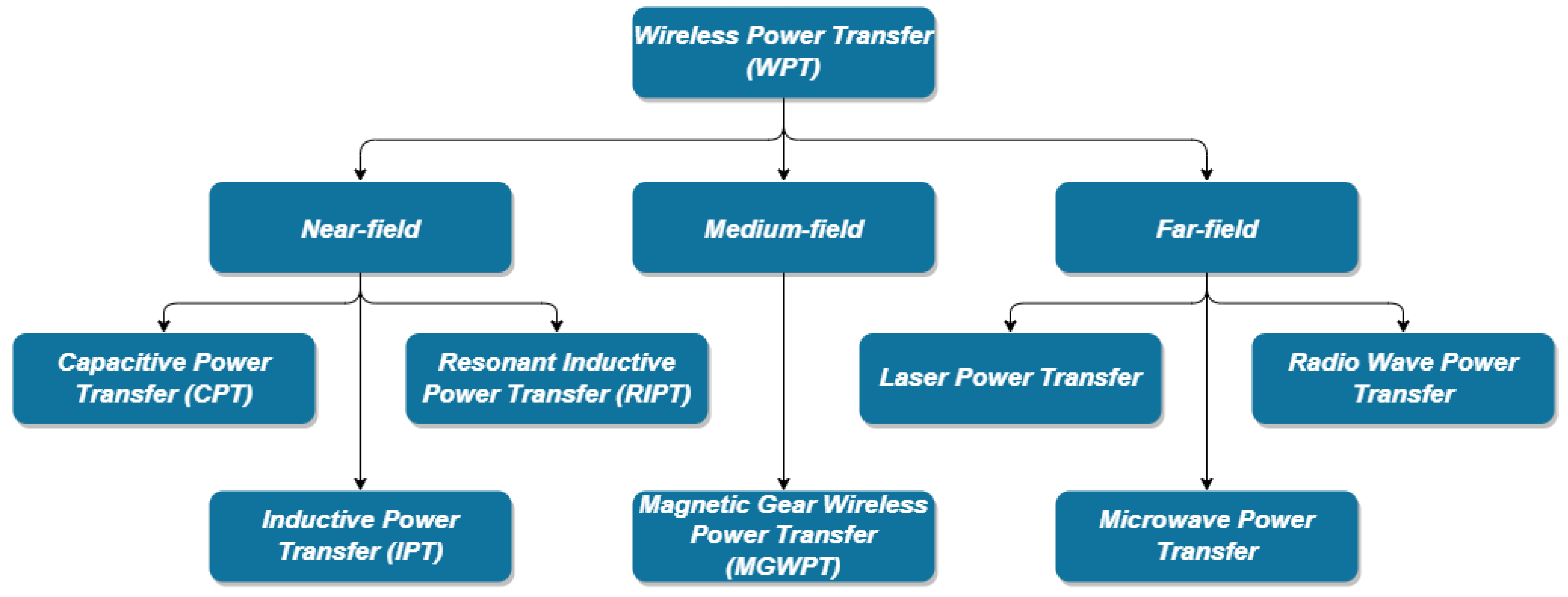
2.1. Near-Field Charging

Near-field charging technologies are capable of transferring power over a distance of less than one wavelength. Near-field WPT methods for wireless EV charging include capacitive power transfer (CPT), inductive power transfer (IPT), and resonant inductive power transfer (RIPT). The typical air gap distance for near-field WPT ranges from 150 mm to 300 mm; however, it may increase for larger EVs [4,5]. The following sub-sections provide details of these methods.

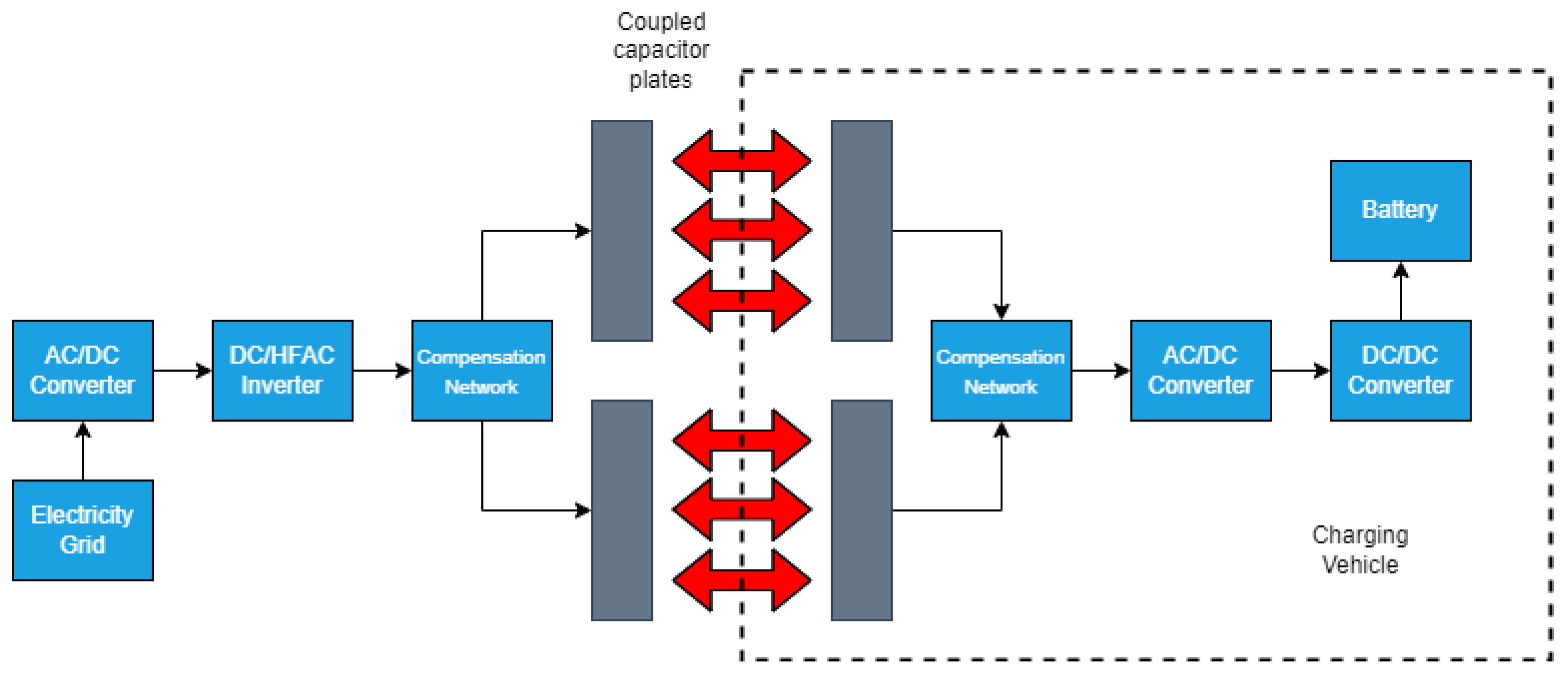
2.1.1. Capacitive Power Transfer (CPT)

Capacitive power transfer (CPT), or charging by capacitive coupling, is a low-cost WPT method that is often employed in applications with a low power requirement, like portable electronics. However, this method can also be used for wireless EV charging, albeit with some limitations. In a CPT system, power is transferred from the Tx to the Rx by means of an electric field established between coupling capacitors. The operating frequency range is in the kilohertz (kHz) range, from 100 kHz to 600 kHz [4]. Figure 5 shows a diagram of a typical CPT system. In terms of developments in this technology, it is proposed in [15] that the vehicle’s bumper may be used as a receiver, potentially reducing the air gap between the coupling plates. This suggestion was supported by a laboratory demonstration of a prototype that achieved approximately 83% efficiency at 540 kHz (>1 kW). Furthermore, high-capacitance designs and solutions for air gap reduction are suggested in [16].
One advantage of CPT is lower levels of electromagnetic interference (EMI) compared to inductive power transfer methods. Additionally, the performance and efficiency of CPT systems are high for a smaller air gap [17]. Another advantage of CPT is the low cost and simplicity of the systems [15,18]. However, the application of CPT for wireless EV charging has been limited because the power transfer levels are very low and can reach up to only 7 kW over a very short distance for power transfer. [1,5]. Hence, smaller air gaps and resonance-based converters may be required to achieve a good power transfer efficiency. It is important to note that the dielectric material between the capacitor plates is only air, which has a low permittivity of approximately 8.85 × 10 12 F/m, and this fundamentally limits the coupling efficiency. Special materials with a high dielectric constant to increase the capacitance are proposed in [19]. However, the use of such materials is costly and intricate. Thus, these reasons limit the extent to which CPT technologies are used in the application of wireless EV charging.

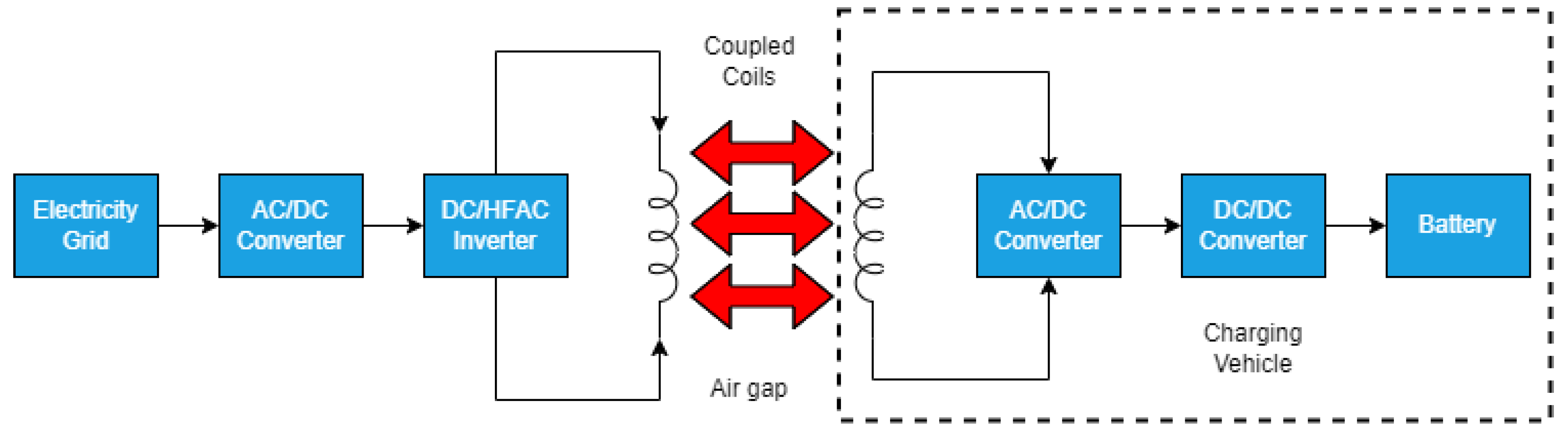
2.1.2. Inductive Power Transfer (IPT)

Inductive power transfer (IPT), or charging by inductive coupling, is a popular WPT method in which power is wirelessly transferred from a primary inductor to a secondary inductor by EM induction under a coupled regime. Figure 6 presents a basic diagram of a traditional IPT system. Generally, the power transfer range is 3–6 kW for distances of 4–10 cm, with efficiencies of 90% or more for smaller distances [1,4]. Typical operating frequencies range from 10 to 50 kHz. The Chevrolet S10 EV was introduced by General Motors (GM) in 1996 and it was charged by the magne-charge IPT (J1773) system [20]. This system was able to provide 6.6 kW (level 2—“slow”) and 50 kW (level 3—“fast”) charging. Moreover, researchers from the University of Georgia developed and demonstrated a 6.6 kW charger that was capable of charging a battery from 200 to 400 V at an operating frequency of 77 kHz [21,22]. Among other advantages, a 10 kVA coaxial winding transformer allowed for a flexible power range and coupling design.
Although IPT systems are more widespread and more efficient than capacitive coupling methods of WPT, there are still some challenges that are encountered with these systems. One challenge is addressing the rapid decay in power, and thus efficiency, with an increase in distance [5]. To ensure high efficiency, the range of separation of the transmitter and receiver pads is limited to a few centimeters in practice. Moreover, Ref. [4] reports that, while characterized by a relatively low cost and simplicity, IPT systems cost more than CPT systems. Other challenges associated with them are the designs of the pads and pickup coils [23,24,25], EM field protection [8,26,27], power converters (high frequency) [28,29,30,31], and metal object detection. Traditional IPT is overshadowed by the benefits offered by resonant inductive power transfer (RIPT), which addresses most of the issues with IPT.

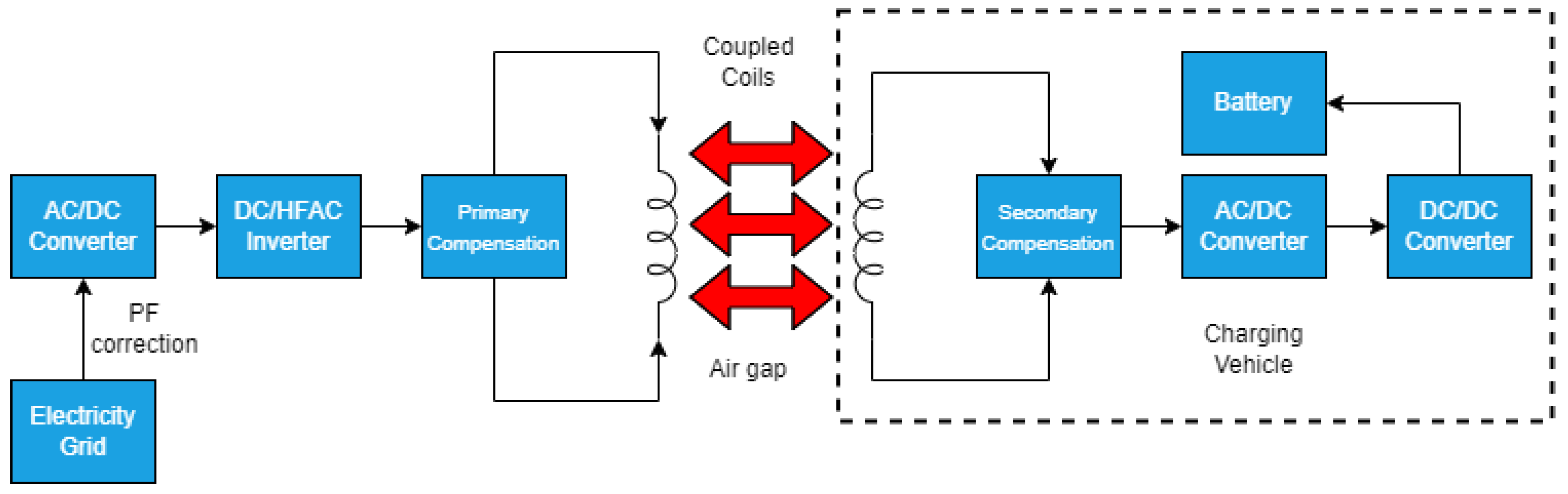
2.1.3. Resonant Inductive Power Transfer (RIPT)

RIPT is an advanced version of the traditional IPT. It is a well-known WPT method that has attracted significant interest over the years because of its improvements over traditional IPT. The schematic diagram is shown in Figure 7. RIPT offers an extended power transfer range, which is reported to be between 1 and 5 m, and a higher efficiency, with power levels that can reach up to 100 kW [32]. This is achieved by the use of compensation capacitors or compensation networks that reduce additional losses and create the case of resonance, as shown in (1).
f r = 1 2 π L C
where f r is the resonant frequency, and L and C are the self-inductance and capacitance values, respectively, of the primary and secondary coils. It follows that efficient power transfer is possible when the resonant frequencies of the primary and secondary sides are matched [4]. Generally, the operating frequency of a RIPT system ranges from 10 kHz to 150 kHz, which is higher than traditional IPT. One problem encountered at high frequencies, however, is that the magnetic flux generated significantly reduces the mutual inductance due to the absence of a magnetic core. Thus, the coupling coefficient k, which is calculated using (2), is lowered.
k = L m L p L s
Lp is the self-inductance of the primary coil, Ls is the self-inductance of the secondary coil, and Lm is the mutual inductance. When the primary and secondary coils are strongly coupled, the mutual inductance is higher, giving an improved k. Typically, values of k for RIPT vary from 0.2 to 0.3 because of the 150–300 mm minimum height clearance required for EVs [33]. Alternatively, the coupling coefficient can be improved by utilizing magnetic ferrite cores [34].
Skin and proximity effects are considerable and can affect the power transfer efficiency at high frequencies. Normally, an individually insulated thin twisted litz wire is used to avoid such problems [3]. The resulting effect is a reduction in parasitic resistances and an improvement to the quality factor Q of the coil, which is calculated using (3). The resistance of the coils is R, L is the self-inductance (primary or secondary), and f is the frequency.
Q = ω L R = 2 π f L R
It is proposed in [32] that RIPT technologies may be implemented in four phases: phase 1, phase 2, phase 3, and phase 4. Phase 1 is implementing RIPT infrastructure in residential areas. Phase 2 involves installing those systems in parking spaces. Phases 3 and 4 involve on-street parking and dynamic charging systems, respectively. Phases 2 through 4 would require additional support from governments. RIPT is the most popular and preferred WPT method used for wireless EV charging applications. An example that supports this claim is the UK government’s allocation of 40 million pounds for research into magnetic-resonance-based charging technologies like RIPT [35,36]. This involves studying street-level wireless charging solutions, commercial vehicles, etc. Oak Ridge National Laboratory (ORNL) is another key research institution in the field of wireless EV charging. Researchers have demonstrated an RIPT system that is able to output 120 kW. This is comparable to a Tesla supercharger. The RIPT system is capable of transferring a high power of 100 kW over 1 m with 90% efficiency. Similarly, a 100 m, 20 kW RIPT test track was constructed by Qualcomm in France [1].

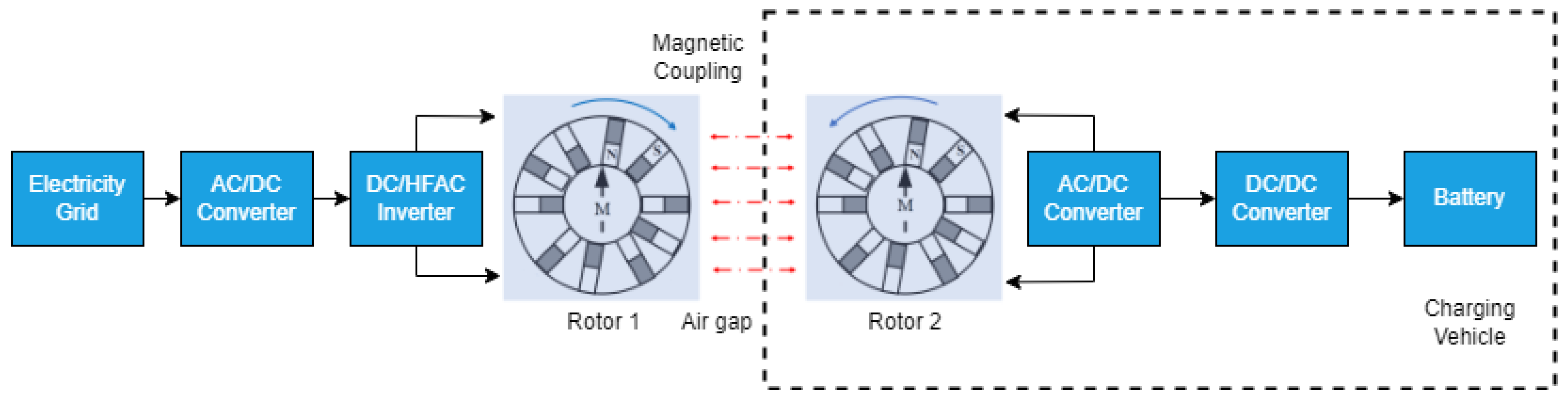
2.2. Medium-Field Charging (Magnetic Gear Wireless Power Transfer or MGWPT)

Fundamentally, magnetic gear wireless power transfer (MGWPT) is different from capacitive and inductive WPT methods. Magnetic gear technology was first proposed as an alternative to conventional contact gear [4]. In MGWPT systems, power is transferred wirelessly via two synchronized permanent magnets (PM) positioned side by side. This arrangement is in contrast to the coaxial arrangement in other wireless charging systems. Figure 8 shows a schematic diagram of an MGWPT system. A mechanical torque is produced on the primary PM when the primary winding is fed from a current source. Torque is then induced on the secondary PM from the resulting rotation of the primary PM. In this regime, the secondary PM works as the generator mode and delivers the power to the battery through the power converter and the battery management system (BMS) [20].
Although there have been applications of MGWPT systems in wind power generators and low-power applications, such as medical implants, these systems have enjoyed limited implementation in wireless EV charging. Generally, MGWPT systems are implemented in low-power charging applications, such as for a range of 1.5–3 kW. As reported in [37], a laboratory prototype was capable of delivering 1.6 kW over a distance of 150 mm. The work also mentions the challenges associated with the system. In particular, constant adjustment of the rotation speed and an advanced feedback system from the battery to the primary side are required to prevent exceeding the upper power limit. During testing, the rotators lost the synchronization speed at 150 Hz, which marked the upper limit for the system, and this significantly affected the power transmitted. Secondly, the design, price, and overall intricacy of the systems are generally higher than inductive- and capacitive-based WPT methods. The level of power transferred is also relatively lower than in those systems. Lastly, it has been observed that power transfer is inversely proportional to the axis-to-axis separation of the PMs. This entails misalignment significantly reducing the coupling between the two synchronized windings. For this reason, the implementation of MGWPT systems has been challenging for dynamic charging applications. Be that as it may, these systems are still usable and promising for static charging situations [3,38].

2.3. Far-Field Charging

Far-field charging technologies are expected to be the future means of charging EVs wirelessly due to their promise of high range, high power levels, and high efficiencies [4]. However, intensive research is still required to make these technologies viable for wireless EV charging applications. Power in far-field technologies can be transferred, in principle, from a distance of two wavelengths to infinity by EM wave propagation. Examples of far-field WPT methods include laser charging, microwave charging, and radio wave charging. The origins and early beginnings of far-field WPT are extensively covered by [39].

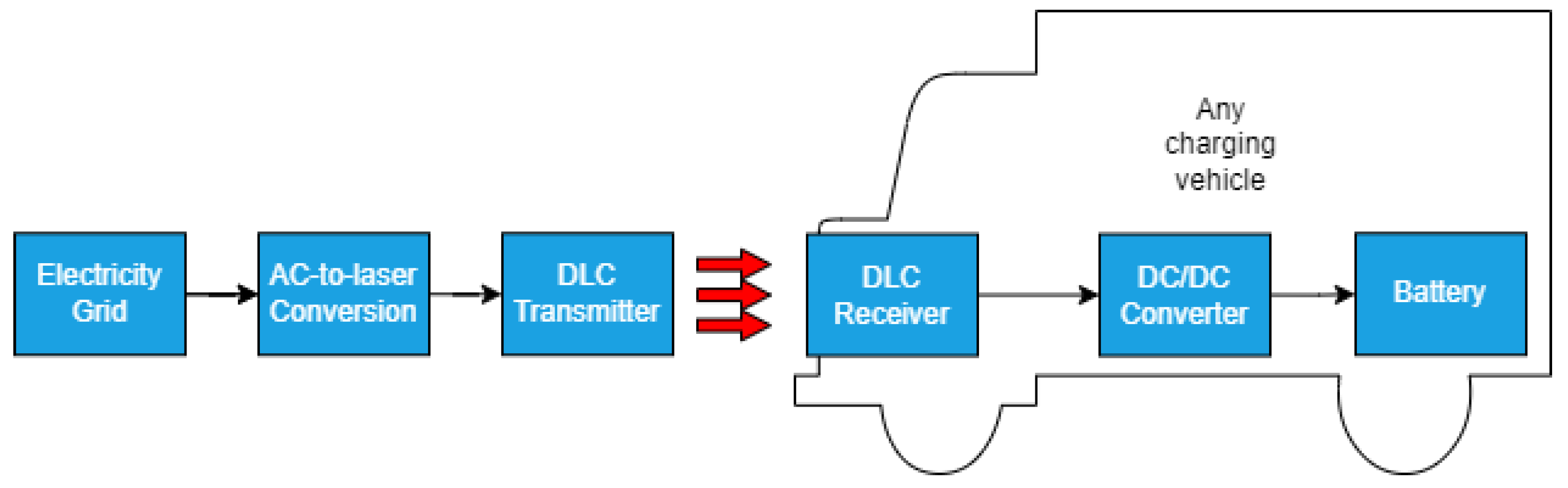
2.3.1. Laser Charging

Although it has seen only a few practical applications in recent years, such as in drones, autonomous rovers, and orbital vehicles, laser charging is seen as a promising WPT method for the future of wireless EV charging due to the benefits associated with laser transfer. According to [1,40,41], power in such technologies is transferred using resonating beams that can have frequencies of up to 359 THz. A distributed laser charging (DLC) transmitter generates and transmits a resonating beam, which is then received by a DLC receiver. The received beam is passed through a DC chopper (DC–DC converter) for output-voltage control to charge the battery. A diagram of the system is shown in Figure 9.
A major issue faced with laser power transfer, as with other far-field WPT methods, is that a direct line-of-sight (LOS) path is needed to transfer power [42,43]. Any loss in communication or connection between the transmitter or receiver stops the charging process. Additional problems include the need for large antennas and complex tracking mechanisms [4]. Research is being performed to make laser charging sustainable and viable, especially for wireless EV charging. The Japanese space agency JAXA has been actively pursuing targeted research and development of far-field WPT technologies for some time now. It is reported in [44] that JAXA is developing a system based on laser transmission that is capable of transferring 10 MW over 10 km. The way that such a system can be developed for EVs is still being researched.

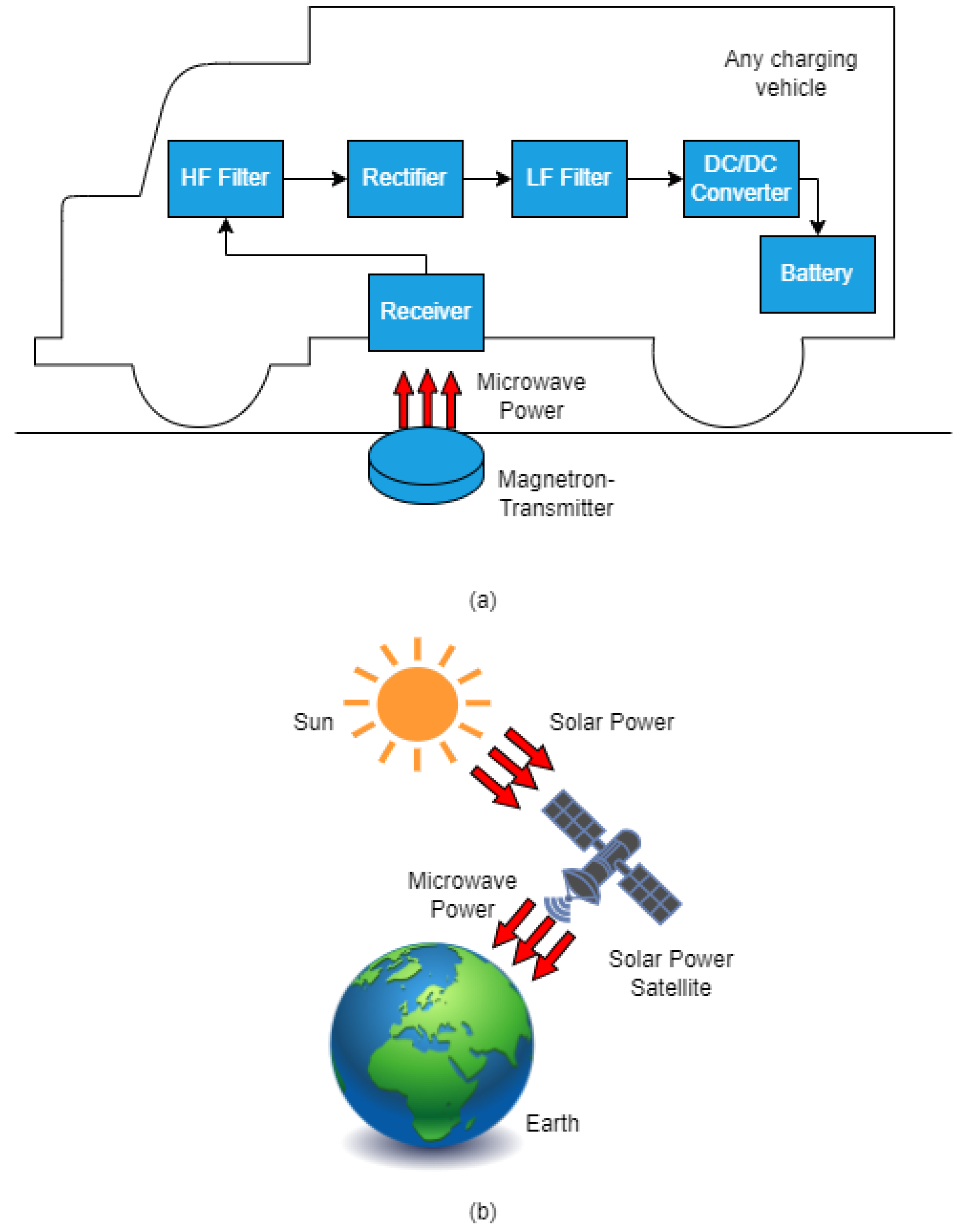
2.3.2. Microwave Charging

Like laser power transfer, microwave power transfer has been tested for several applications, such as experimental terrestrial vehicles. These applications involve power transfer over large distances. In terms of power transfer characteristics, microwave charging is similar to laser charging. The difference is that microwave power transfer technologies have enjoyed far more successful testing than laser power transfer technologies.
In a 1975 experiment conducted by the Jet Propulsion Laboratory (JPL), 30 kW of power was enclosed from a dish antenna 26 m in diameter to a rectenna (rectifying antenna) with a maximum efficiency of 85% over a distance of 1.54 km [45]. A wirelessly powered airplane first took flight in Canada a few years later, in 1987 [46]. The airplane was powered by a microwave emitter situated on the ground, making it the first microwave-powered airplane.
There have been some advances in powering EVs using microwave power transfer. However, these technologies are not entirely applicable for EVs just yet. The biggest drawback is the same as that of laser charging, which is the halt of the power transfer process when the link between the transmitter and receiver is disrupted. Thus, microwave charging systems require large antennas, direct LOS transmission, and complex tracking mechanisms. Still, a system proposed in [47] involves a magnetron capable of transferring a power of 10 kW over 5 m with an efficiency of 80% at an operating frequency of 2.45 GHz. Figure 10 shows a microwave WPT system.

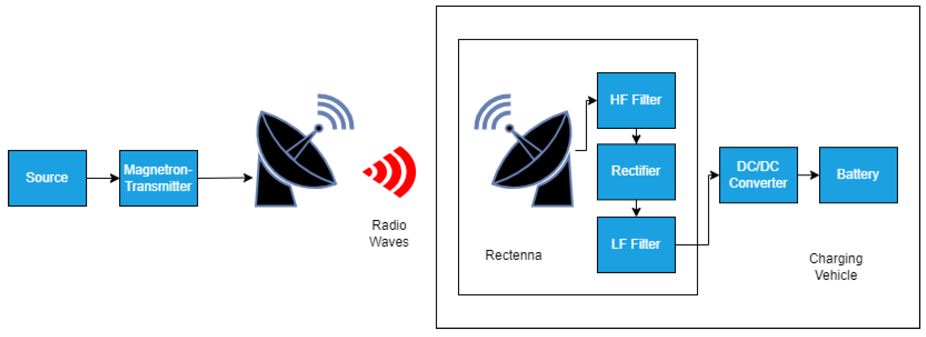
2.3.3. Radio Wave Charging
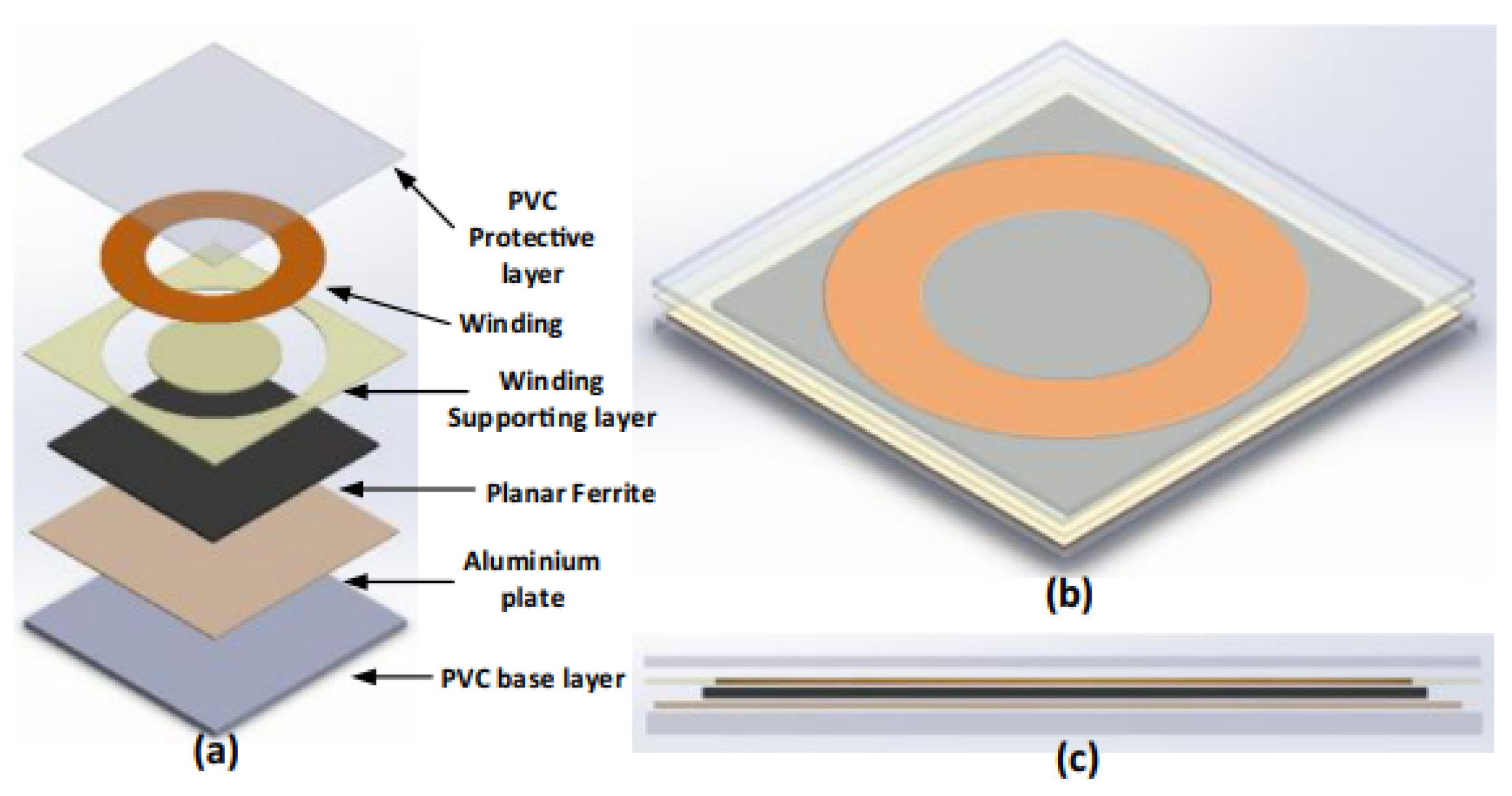
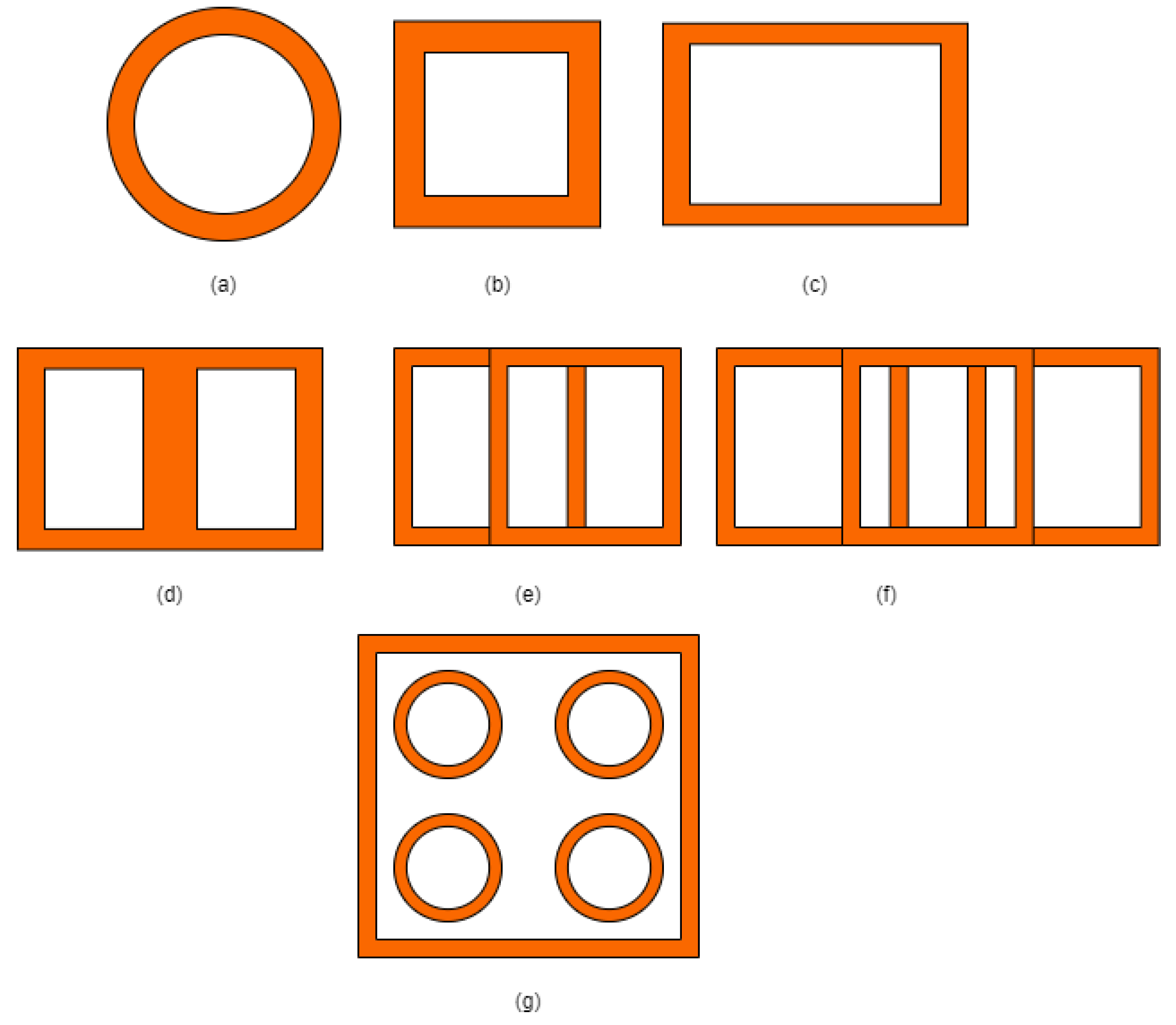
Radio wave charging is another far-field WPT method. The efficiency of current radio wave charging systems is too low for wireless EV charging applications [45,48]. Additionally, a direct LOS is required for uninterrupted charging, as with the previous two far-field WPT methods. Characteristically, and similar to microwave WPT, power from the transmitter is received by a rectenna that includes an HF filter, a rectifier, and an LF filter to obtain a smooth DC voltage to charge the battery, as shown in Figure 11. More research is required to make this WPT method viable for wireless EV charging.

2.4. Coil Designs

There is great discussion on the coil designs for the transmitter and receiver pads in inductively coupled WPT systems (IPT and RIPT). The different design options provide more possibilities for achieving efficient power transfer. Studies such as [3,4,6,7,49,50,51,52,53,54] discuss and compare the design and features of various coils for the transmitter and receiver pads to an extensive degree. Structural and design features of the transmitter and receiver pads for near-field WPT methods that use inductive coupling can be loosely translated for those that use electric fields to couple the GA and VA, such as CPT. One study, [18], advocates for CPT as an effective WPT method and presents a detailed analysis of the power flow in such a system. The system proposed is a charging platform with a matrix charging pad and a transformer with dynamic soft switching for output-voltage regulation and power-flow control in different operating conditions. The study also verifies the findings using simulations. However, more emphasis is put on optimizing coil design and pad structures for the transmitter and receiver for inductively coupled methods due to their popularity. Similarly, this section discusses the work performed in that regard. The design philosophy may be extended to other near-field WPT methods.
Fundamentally, an inductively coupled WPT system consists of two interconnected coils that facilitate the transmission of power through coupled magnetic fields. An electric current is directed through the primary coil, generating a magnetic field that varies over time. The secondary coil intercepts the changing magnetic flux, resulting in electromotive force (emf) induction. Several factors influence the magnitude of the induced emf. These factors include the distance between the coils (air gap length), the number of coil turns, and the rate of change of the magnetic field. The induced emf, in turn, causes an electric current to flow within the secondary coil. Therefore, the coils collectively form a loosely coupled transformer, with their connection established through a primary magnetic flux path. This path includes leakages of magnetic flux that do not contribute to power transfer and reduce overall efficiency. To optimize the current flowing through the coils, each coil is linked to a compensation network, which enhances resonance. When designing the primary and secondary pads, the main objectives should prioritize achieving maximum values of the coil quality factor Q and the coupling coefficient k. Such an optimized design results in a high tolerance for accommodating increased air gap distances and lateral and/or longitudinal shifts [3].
Practically, the transmitter and receiver pads consist of multiple layers of components, which are carefully designed to achieve optimal power transfer efficiency while simultaneously reducing EMI in a cost-effective manner. These wireless transformer pads primarily comprise three key elements: the coil, shielding materials (comprising ferrite and aluminum plates), and layers dedicated to protection and support. Figure 12 provides various views of these wireless transformer pads. The transmitter pad is set beneath the concrete paving of the road and is strong enough to support the weight and added vibration of an automobile. The top and bottom sections of the charging pads are made from a PVC plastic sheet to provide structural stability. The dimensions of the length and width, which range in size from 5 mm to 20 mm, depend on the size and thickness of the charging pad. Furthermore, clear acrylics may occasionally be put around the coil for stability and to improve the charging pad’s aesthetic [4].
A major issue that arises in the “air-core wireless transformer” model of the WPT system [4] is the effect of misalignment between the transmitter and receiver pads. Misalignment is unwanted as it introduces system losses and fundamentally reduces transfer efficiency. To solve this issue and ultimately improve the transfer efficiency, many planar coil structures have been utilized, and further improvements have been proposed [55]. According to [56], the coils can principally be categorized as either non-polarized pads (NPPs) or polarized pads (PPs). NPPs are of conventional shapes such as circular, square, rectangular, and hexagonal, are made from a single coil shape, and produce only the perpendicular flux components. On the other hand, PPs are made from multiple coils in various shapes to produce both perpendicular and parallel flux components. Examples of PP designs include solenoidal coils, double D (DD), double D 1uadrature (DDQ), bipolar (BP) and quad D quadrature (QDQ). PPs are generally used to address the relatively poor horizontal misalignment tolerance of NPPs, and are created by arranging several coil shapes in different arrangements. Such geometries are ideal for three-phase applications in addition to single-phase applications. The various coil shapes are shown in Figure 13.
There are no sharp edges in the circular coil, and hence, the eddy currents are minimized. This makes the circular coil a popular design choice for wireless transformers. Additionally, the distribution of the magnetic flux can be altered by varying the internal diameter. The magnetic field lobe would have a spike shape for lower center diameters, which could help increase the coupling coefficient. The magnetic flux distribution zones can be expanded with less amplitude sacrifice by increasing the center diameter, which can help with misalignment issues [53]. It may be important to note that for the circular coil, the receiver power drops to zero when the offset distance between two windings reaches about 40% [52]. Due to their perfectly aligned sides, square and rectangular coils are useful when they need to be arranged in an array. However, because of the eddy currents generated by the sharp corner edges, which also increase impedance and hot spots, they increase inductance. Because of this, square and rectangular coils are inappropriate for high-power applications. Compared to circular and square coils, rectangular coils have greater tolerance for horizontal misalignment. Hexagonal coil shapes offer the greatest efficiency in power transfer at the center of the transmitter and receiver coils, but with a significant loss in power as it approaches the coil’s edge [54]. Similarly, oval-shaped coils offer greater tolerance for misalignment, but they are not appropriate for high-power applications [49].
On the NPP side, solenoidal coils are wound in series around a flat ferrite plate in order to produce polarized and sharply arching magnetic fluxes on both sides of the coupler [57]. These polarized fluxes surpass the fluxes of the coils in NPPs [58]. DD polarised pads, made from two square or rectangular coils, generate flux in one direction with minimal leakage fluxes, covering both horizontal and vertical directions, and providing excellent coupling coefficient and quality factors [59]. The DDQ coil is an advanced version of the DD pad, producing twice the flux height and improving lateral misalignment issues. It is suitable for single or three-phase power source applications, grabbing both sine and cosine magnetic flux vectors [60]. BP charging pads use multiple coils, requiring 25–30% less copper than DDQ pads, but the coupling coefficient drops by 13% with a 30° angular misalignment [59]. QDQ pads enhance wireless transformer performance by utilizing circular and square coils for misalignment and flux height, improving overall performance. These pads are able to transfer enough power with 50% misalignment movement and have a substantially higher coupling coefficient (0.33 at 150 mm air gap) [49,61].
To enhance the connection between coils, magnetic cores can be employed to direct magnetic flux. The primary losses within the coil system are attributed to the core losses associated with the ferrite material and the resistive losses within the coils. These resistive losses encompass proximity and skin-effect losses. The use of litz wire helps mitigate skin-effect losses, while core losses are contingent on the core material. To minimize core losses, it is important to maintain the magnetic flux density below the saturation level of the material. Furthermore, the available design choices are constrained by both power limitations and spatial constraints [3]. Additionally, magnetic flux generation in medium-to-high power ranges requires safety standards to avoid health issues. It affects the coupling efficiency between two windings, especially without shielding to reduce leakage fluxes. In essence, the selection of cores and core materials is a whole research area in itself. The proper design of magnetic ferrite cores can redirect path to magnetic fluxes, improve mutual inductance and self-inductance of coils, and reduce leakage fluxes [4].
The choice of ferrite core for EVs is influenced by factors like size, shape, permeability, operating frequency, and cost. Basic shapes like circular, square, and rectangular are used on both the source pad and receiver side to minimize leakage fluxes. Ferrite bars have been modified to reduce weight and cost, depending on the application. EE-core, U-core, ETD, and pot ferrite shapes offer higher coupling coefficients but are not suitable for EVs due to limited ground clearance. Striated ferrite structures are used to reduce leakage inductance and enhance cost effectiveness. Higher permeability materials like Mn–Zn are the best option due to affordability and availability [4]. Alternatively, aluminum plating provides shielding and structural integrity, reducing flux leakages and improving the coupling coefficient. The aluminum plate sizes range from a few millimeters to several millimeters, higher than the skin depth characterized at an operating frequency range of 20 kHz to 100 kHz. The aluminum structure prevents magnetic fluxes from passing through the surface, increasing the length of the magnetic flux contour and weakening the flux values due to higher magnetic path resistance. Aluminum plates are typically placed under ferrite structures, as without such materials, the mutual inductance of coils is reduced. Also, ferrite plates are fragile and may be constructed from multiple smaller planar blocks due to limited availability of larger planar plates.

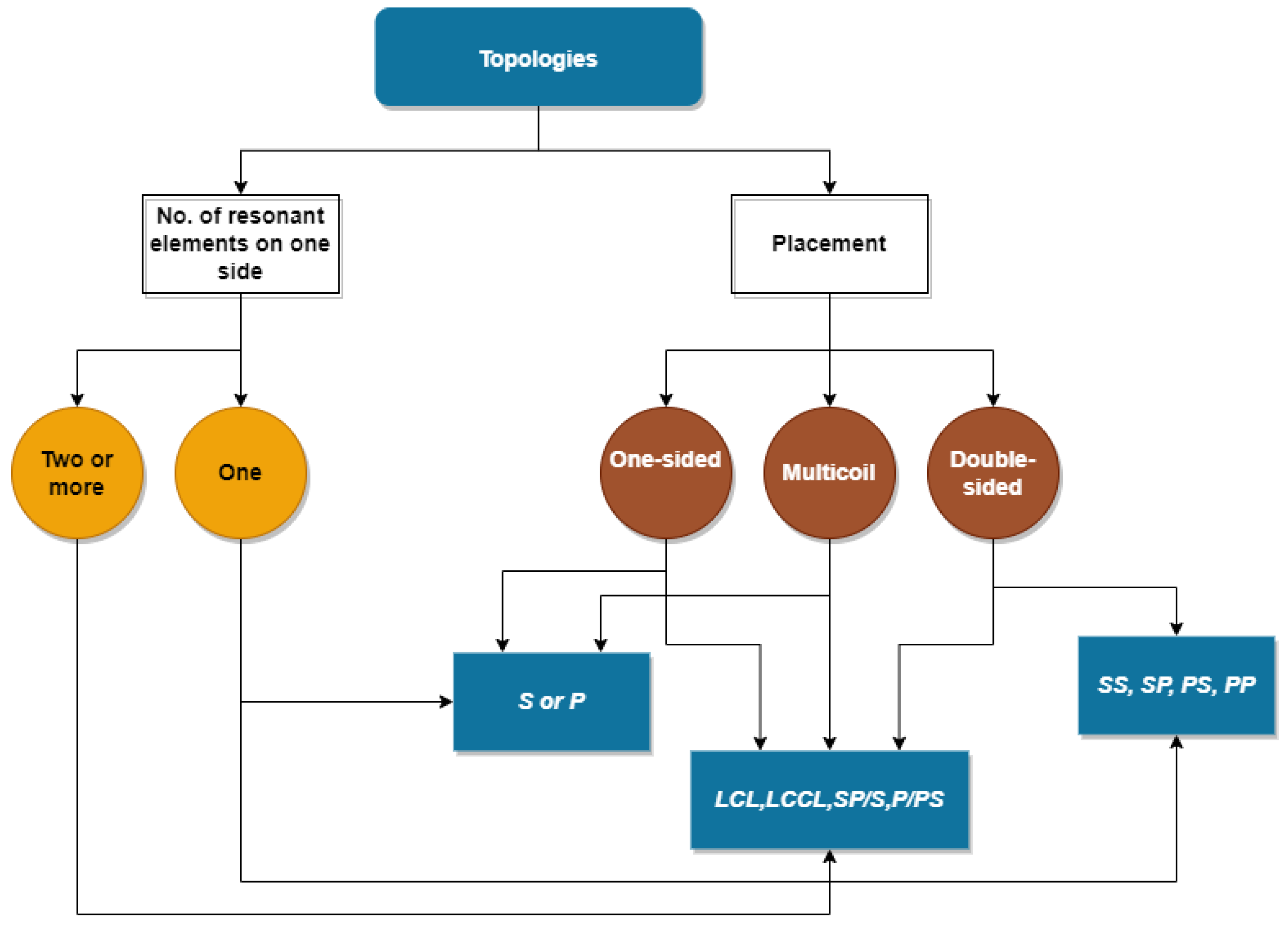
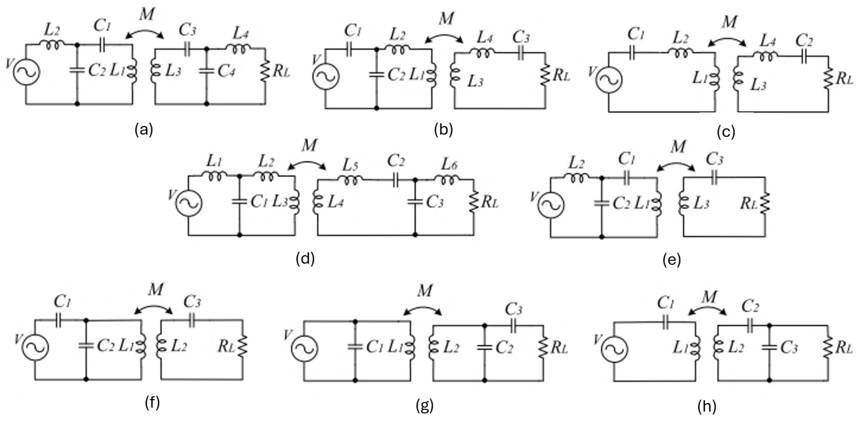
2.5. Compensation Topologies

The primary and secondary coils in IPT are magnetically coupled, and the system essentially acts like a transformer. However, the leakage inductance is high due to the large air gap; hence, the level of magnetic coupling is low. If the system operates at the resonant frequency characterized by its reactive components, then it is possible to tackle this issue and transfer enough power over larger distances. Compensation networks (also referred to as topologies in some of the literature) are used to achieve the state of resonance. The reactive elements, capacitors and inductors, are linked together in various configurations in compensation networks. As per Figure 4, the compensation networks are placed either between the HF inverter and the primary coil in the GA or between the secondary coil and rectifier circuit in the VA, or they are placed in both sections.
Generally, compensation on the primary side is required to eliminate the phase difference between source current and voltage and reduce the reactive power rating by canceling out the reactive component of the primary coil. On the secondary side, compensation maximizes power transfer to the load as resonance is achieved. Another advantage of compensation is that it enables soft switching of the semiconductor devices. Classical topologies, shown in Figure 14, include series–series (SS), series–parallel (SP), parallel–series (PS), and parallel–parallel (PP) configurations. The order of appearance of “P” and “S” denotes the configuration of the reactive components on the transmitter side and then on the receiver side. Additionally, there has been an increasing interest in enhanced and hybrid topologies over the years. These topologies include LCL, LCCL, SP/S, P/SP and other modifications to the classic or basic networks, where L and C stand for inductances and capacitances added to either side of the system, respectively. Although the figures depict inductively coupled WPT systems, a similar architecture of compensation networks can be employed for other WPT methods, such as CWPT. A highly comprehensive and convenient classification scheme for compensation topologies is proposed in [50] and is shown in Figure 15.
Although alternative topologies have certain advantages over basic topologies, the networks are more complex and costly. The addition of more reactive components, such as inductors, increases the complexity of calculations and the difficulty of predicting system behavior. Moreover, the addition of more elements inherently decreases the reliability of the network.
Numerous studies, that are summarized comprehensively in [3,7,50,51], have extensively researched the performance of the aforesaid topologies. It has been noted that SS and SP are generally more favored among the basic topologies for a variety of reasons. Mainly, the series configuration on the primary reduces the power supply rating needed, solely because the elimination of the phase difference between the current and voltage reduces the reactive power rating, as mentioned previously. It is also found that the SP topology has a load-independent output voltage characteristic [7], making it advantageous for wireless EV charging applications. There are some drawbacks, however, as misalignment and large air gaps can cause a no-coupling-factor situation, which is unsafe for the power supply [62].
In a similar vein to the basic networks, hybrid and alternative topologies have been studied (Figure 16). Although relatively recent, this area of research aims to maximize desirable results through the use of higher-order compensation networks. For example, LCL compensation, which is usually placed on the primary side [7], protects the capacitor from large instantaneous changes in the voltage, such as the output from the inverter. Thus, the lifespan of the capacitor is increased. Furthermore, LCL compensation enables a load-independent constant current operation and offers some higher-order harmonic filtering as well. Other higher-order and hybrid topologies offer similar performance.

2.6. Converter Topologies

Converters are a vital part of a wireless charging system (Figure 4). There are several types of converters that are typically used, depending on the type of WPT system and the application. One of the benefits of incorporating converters in the system is power supply control on the primary side, while on the secondary side, the load parameters can be controlled. There is a great deal of specialized research on converters for WPT applications, focusing on power electronics and control dynamics. One such study, which summarizes most of the work in the existing literature, is [7].
The main goal in the design of converters is the conversion of power levels at various stages in the system and, in the same context, to achieve resonance. As in the case of compensation networks, resonance increases power transfer efficiency. Rectifiers and inverters are implemented on the primary side, while a rectifier and/or a DC–DC converter may be used on the secondary side. The Society of Automotive Engineers (SAE) has standardized a bandwidth of 79–90 kHz, although an operating frequency of 85 kHz is recommended [51]. Inherently, each converter in the system has losses that need to be minimized. One way to minimize losses is to reduce the number of converters required by implementing an efficient system architecture. In [63], an AC–AC converter is used, which eliminates the need for a primary side rectifier. Other proposed converter topologies include an E 2 class DC–DC converter, and isolated buck-boost converters and their configurations, Cuk, Zeta, SEPIC, and P5 [7].

2.7. Communication Systems

Both the GA and VA generally share information via a communication link (Figure 4). This data transfer is important to the system for feedback and control [3]. Examples of the usefulness of data transmission in wireless-charging EV systems include battery monitoring, load control, and object detection as a safety measure. Furthermore, communication with the GA grid connection can be used to manage demand according to the status of the grid.
Operationally, the VA detects the GA and requests a charge. The GA, in turn, either approves or denies the request. If the request is approved, the charging requirements, such as the power level, state of charge (SoC), ground clearance, and misalignment, are transmitted. The communication is maintained even during the charging process, as the SoC, vehicle position, and alignment are constantly monitored to increase the power transfer efficiency. A payment method can be implemented after the charging is completed via the same communication link.
The literature includes several works that address the communication between the installed charging infrastructure and the EV. Examples of these studies include [64,65,66], which discuss the importance of implementing a communication system between the GA and VA and propose methods such as a two-way communication (duplex) system to establish a link. Building on the suggestions for a robust link between the GA and VA, Ref. [67] discusses cybersecurity measures in communication networks that are rapidly being implemented in EVs. The work provides an overview of the developments made in monitoring and control strategies and explores several case studies of recent cyberattacks on charging stations.
One notable work that provides an overview of the different techniques present in the literature and proposes models for simultaneous communication between the GA and the VA is [68]. The work investigates the single link–dual carrier (SLDC), single link–single carrier (SLSC), and dual link–dual carrier (DLDC) techniques. Owing to their fundamental methods of operation, SLSC does not allow for high data rates, while DLDC is characterized by a low data signal SNR, higher complexity, and increased infrastructure costs. Hence, it is concluded that SLDC is the most suitable technique for wireless EV charging systems. SLDC utilizes two carriers with a single communication link, which allows for independent control of the power and data signals. Moreover, high data transfer can be achieved with minimal interference between the power and data channels.
Foreign object detection (FOD) is used to distinguish between living and non-living objects, or between conductive surfaces and other EVs. It is a key component that can be used to detect coil misalignment and monitor charging performance [69]. For example, the system may prevent power transfer if objects are detected between the charging pads. A major advantage of this mechanism is added safety against hazards such as the heating of conductive objects and EM exposure to humans and animals. Another benefit is that it also prevents system losses by halting the power transfer process if the Rx in the VA is not near or is severely misaligned with the Tx in the GA. FOD solutions that are discussed in the literature mostly include methods that involve sensors and, thus, can be inductive, capacitive, or optical in nature [69,70,71,72]. In the case of dynamic wireless charging systems, vehicle detection has emerged as an active research area. In one seminal work, a three-coil system was designed and tested by researchers at the University of Auckland [73]. The system was able to detect approaching EVs of different speeds, ground clearances, and horizontal misalignments.

3. Operations and Systems Background

Apart from the ongoing research in the technical aspects of wireless EV charging, there has been a considerable amount of work performed towards studying the operations and systems perspective. Such a perspective looks at the problem of wireless charging from operational, managerial, and strategic points of view. The survey in [2] meticulously reviews the ongoing operations and systems research in great detail. Current areas of research can be reviewed from the following points of view: allocation of the charging infrastructure, extension of the driving range, costs and benefits, environmental assessments, billing strategies, system installation, and other miscellaneous yet practical perspectives. However, a single research article might be examined from multiple viewpoints simultaneously because the areas mentioned above are not entirely distinct. Furthermore, greater strategic planning and optimum resource allocation are generally needed for dynamic wireless charging systems. Therefore, most studies review the operations and systems of dynamic charging, and this section similarly follows this trend.

3.1. Charging Infrastructure Allocation

One of the most researched areas in operations and systems studies, the allocation model provides strategic insight and enables optimal distribution of charging infrastructure for EVs. The topic has already been widely discussed for traditional EVs. Typically, based on the scope of the application, the models may be divided into two types: the microscopic allocation (micro-allocation for simplicity) model and the macroscopic allocation (macro-allocation for simplicity) model. The primary objective of using this model is to leverage a practical and effective engineering tool that aids in making system-level decisions for transit systems using wireless charging. Generally, mathematical optimization is used for both the allocation models. The optimization is performed for two purposes: firstly, it can be used to directly identify the positions for charging infrastructure, and secondly, it can assist in various intermediate stages of finding the optimal allocation. An instance of the latter application is when an optimization technique is used to assess the user equilibrium assignment, as demonstrated in [74]. In the research conducted by [75,76,77,78], the user equilibrium concept is integrated with the allocation process for charging infrastructure. In the available literature, there are three distinct decision-modeling approaches used in the aforesaid models. The first approach, called the continuous variable approach, models the allocation of the charging infrastructure with the continuous variables x i 0 and x i f , the start and end points, respectively, of a charging track i along a continuous path. In the second approach, a segmented discrete variable is employed, whereby the roadway is partitioned into several segments. A binary variable, usually taking values from the set { 0 , 1 } , is utilized to indicate whether a power track or charging lane is present in a given segmented path. In the third approach, known as the link-variable method, a decision variable is associated with a particular link within the system. These approaches are shown in Figure 17.

3.1.1. Micro-Allocation Model

The micro-allocation model is used to identify the best possible positions for charging points along a designated vehicle route. This model is utilized for scenarios where EVs exclusively follow a predefined path, like public transport vehicles. Since these vehicles adhere to a set route, factors such as traffic conditions, speed patterns, and energy consumption can be reliably anticipated. In particular, the micro-allocation model proves valuable when precise spots for charging lanes (or stations) need to be determined in the initial planning stage of wireless charging transit systems. Subsequently, more intricate models can be developed based on this framework. Much of the early literature on the subject focused on single-route transit while assuming that the energy supply and consumption rates were deterministic. However, in reality, transit systems typically feature a more intricate configuration, often encompassing multiple routes and bus stations. Additionally, the energy rates are not deterministic and are not known in advance.
The model’s assumptions and considerations can be summarized as follows:
  • Every bus route within the system adheres to a predetermined path.
  • Each bus route is equipped with a central station that serves as the starting and ending point for all bus services.
  • After completing a full service loop, a wireless charging bus will be recharged to full capacity at the central station before embarking on another service circuit.
  • The velocity pattern and the number of passengers getting on or off at bus stops are determined in advance.
In one of the earliest instances of addressing the micro-allocation problem, an optimization-driven methodology was used [79]. This approach was used primarily for two purposes: (1) to distribute charging infrastructure effectively, and (2) to determine an appropriate size for the battery used in a single-route public transportation system operating in a controlled environment. Such environments are usually characterized by regulated vehicle speeds and reduced traffic congestion. An example of this is the On-Line EV (OLEV) bus system developed by the Korea Advanced Institute of Science and Technology (KAIST). Their model treats the route as a continuous spatial-decision space. The objective is to identify the starting and ending points for each segment of wireless charging lanes along an identified route, as depicted in Figure 17a. The total number of these segments is also treated as a variable to be determined. Furthermore, the model incorporates battery capacity as one of its decision variables. There is a trade-off between battery capacity and the length and number of charging lanes. In particular, longer and more charging lanes are needed if the electric bus is equipped with a smaller battery. This highlights the relationship between the cost of the battery and that of the charging lanes. Consequently, this approach establishes an allocation plan for charging lanes while simultaneously identifying the most efficient battery size. In practical terms, this methodology proves most valuable during the initial planning phase of wireless charging transportation systems operating within closed environments, like the one at KAIST [2].
The work in [80] was the first to incorporate battery longevity as a component of the economic evaluation for wireless-charging EVs. Their cost structure and modeling approach, which also includes a scenario featuring a single-route transit bus, closely resemble the methods employed in prior studies such as [79,81]. Battery life is taken into account due to the characteristics of lithium-based batteries, which are the most common types used in EVs. These batteries exhibit diminished performance, including reduced charging capacity and power output, when subjected to deep charge–discharge cycles or infrequent charging. This suggests that it may be economically advantageous to have numerous shorter charging tracks that are used frequently rather than a few long tracks that are used infrequently. In addition, the cost of replacing the battery also becomes influenced by decisions regarding the allocation of the charging track. When making comparisons between economic models that consider battery life and those that do not, the study highlighted the significance of factoring in battery longevity in economic assessments for long-term planning.
For most real-world cases, there are overlaps between routes; hence, new considerations are needed. As evidenced by [82,83], it is more advantageous and effective to allocate charging tracks as segments wherever there is overlap of multiple routes. The work in [82] is based on [79] and provides a generalized model for the case of multiple routes. While the optimization is still based on the continuous variable approach, the algorithm is numerically validated using the segmented discrete variable approach in Figure 17b. On the other hand, Ref. [83] presents a model based entirely on the segmented discrete-variable optimization approach. More importantly, it is the first study to address the concept of uncertainty in the energy supply and consumption of EVs.

3.1.2. Macro-Allocation Model

The macro-allocation model takes into consideration more factors and provides a higher-order perspective for infrastructure allocation than the micro-allocation model. By providing scientific insights for the involved EVs, the model assesses how the integration of wireless-charging EVs impacts the overall traffic dynamics within larger transportation systems. The scope of the model is much broader, and it can be used when there is more freedom in route selection. Many macro-allocation models commonly use a network-oriented modeling method, representing traffic flow through nodes and arcs. This method draws its inspiration from the well-known optimal location problem [84], which aims to identify the best facility location under specified constraints. It is also generally assumed that the traffic flow from the starting point to the destination is known beforehand. Going beyond the scope of a single vehicle following a specified route, the model optimizes the utilization of the infrastructure across a larger number of vehicles. The fundamental assumptions in this approach revolve around the idea that the placement of charging infrastructure can influence the selection of routes and, consequently, the flow of traffic.
The optimal placement of wireless charging stations is explored in [85] using a model called the Flow-Capturing Location Model (FCLM). This model’s aim is to maximize coverage by strategically positioning a set of facilities, drawing on prior works such as [84,86]. The study focuses on solving the challenge of finding the best locations for wireless charging facilities when the number of facilities available for charging is limited. It builds on the Arc-Cover Path-Cover model to explicitly account for the interplay between the placement of charging facilities and the resulting traffic flow within the network. In this optimization model, network links are considered as potential locations for dynamic charging infrastructure. It is also assumed that if a wireless charging facility were provided, it would be positioned at the midpoint of these links (centroid node). Additionally, the proposed model addresses the task of assigning traffic within the network to specific routes, taking into account factors like travel time and the availability of charging facilities. To understand drivers’ routing choices, the multinomial logistic model and the stochastic user equilibrium principle were employed. It is important to note, however, that the optimization model was based on assumptions that may not be realistic. For example, the model assumes that EV batteries are fully charged on a link, regardless of their actual charge level. Another assumption is that all vehicles within the network model are wireless-charging EVs. Despite these limitations, Ref. [85] is recognized as a pioneering work that expanded traditional location models to accommodate wireless-charging EVs, contributing to the field’s development.

3.2. Drive Range Extension Analyses

The studies on drive range extension consider the distribution of the charging infrastructure to extend EV driving ranges through dynamic wireless charging systems. A standardized driving cycle, typically derived from a specific vehicle type’s velocity profile provided by government agencies or organizations, is used in these studies to reflect driving patterns. For instance, in [87,88] a universally standardized driving pattern is utilized to estimate the cost of charging infrastructure, assuming that the allocation of charging infrastructure is optimized. A straightforward optimization method to distribute charging lanes across a standardized driving cycle is also employed in [87]. The study factors in the type of vehicle (whether it is a small or large vehicle or an SUV), three driving cycles (low-demand urban, high-speed highway, and high-demanding mountain), and three different power rates for the track (20, 40, and 60 kW). The optimization model minimizes the total length of the charging track while maximizing the vehicle’s battery life. Admittedly, the proposed model bears resemblance to macro-allocation models to the extent that it deals with the overall travel patterns of vehicles rather than specific individual trips [2]. Similarly, a computational analysis using simulations and employing a conventional highway driving cycle known as the Highway Fuel Economy Driving Schedule (HWFET) was used in [89]. The simulation study was designed to explore the potential enhancement in EV driving ranges by considering different coverage levels of a dynamic CPT charging infrastructure, ranging from a tenth to the full highway, while varying the power level within the range of 10 to 60 kW. The research findings ultimately indicate that an EV equipped with a 24 kWh battery, 25 kW power level, and 40% coverage of the highway can potentially allow for a driving range of 500 kilometers. Another study that also employs a simulation to investigate the potential extension of EV driving ranges through the utilization of CPT wireless charging considered both urban and highway driving conditions [90]. The analysis comprised two distinct case studies, which revealed significant improvements in driving range achievable through the strategic deployment of wireless charging infrastructure. These improvements were applicable either when an EV was in urban areas or on a highway. The research findings indicated that, for an EV equipped with a 24 kWh battery, a power supply with 90% efficiency, and a road coverage of 20%, the projected driving range extension amounted to approximately 12% at 10 kW and a substantial 217% at 40 kW power levels, respectively.
In another study, an analysis of the initial cost of investment for an electric bus fleet aiming for a 400 km driving range was conducted [91]. The study introduced a high-level model for estimating investment costs. To determine the cost of the charging track, the researchers employed simulation and regression techniques. Initially, they simulated standard driving cycles featuring various parameters. Subsequently, relying on the outcomes of these simulations, they utilized linear regression to estimate the connection between the amount of road coverage provided by the charging facilities and the level of the battery’s remaining charge at the end of a trip. The results indicated that an optimal battery size was 500 kWh. However, this outcome, which suggests a considerably large battery capacity, somewhat contradicts the findings in [92], in which a potentially lower battery size is discussed. It is important to note that a direct comparison between these two works is challenging because the simulations used in these studies are configured with different assumptions and parameters. Accordingly, further research is required to determine an appropriate battery size for wireless charging EVs.
A comparative analysis involving an EV with a 24 kWh battery was performed in [93]. The EV was tested across three distinct road conditions: motorways, highways, and urban roads. Each of these scenarios exhibited varying traffic conditions in terms of traffic flow, including intensity and speed, as well as differing road lengths. The research outcomes revealed that, in the case of urban roads, an average of 0.6 kWh of energy per kilometer was transferred to the EV. In contrast, on the highway, this energy transfer averaged around 0.25 kWh per kilometer.
Fundamentally, drive range extension is possible through the strategic placement of wireless charging infrastructure. This may be made possible by understanding how much power can be transferred in different urban settings and at different vehicle speeds. It is evident that the speed of the vehicle affects the transfer efficiency and amount of power transferred with respect to a certain time frame. In particular, higher speeds cause lower transfer efficiency [94], which means that the power transfer levels are low on highways and ideally greater otherwise. Additionally, consideration must be given to the effect of multiple EVs using the same power track on the performance of the GA.
Several works in the literature have explained the relationship between speed and transfer efficiency and also proposed promising solutions to ensure the viability of dynamic wireless charging. The influence of vehicle speed on the level of transferred power is mathematically discussed in [95]. In another study, the researchers suggested limiting speeds within allowable bands for an optimum scenario based on simulation results [96]. Moreover, an early work on power transfer control in dynamically charging EVs discussed a control method that adjusts the transmitted voltage and the equivalent load resistance in the EV [94]. The proposed method was simulated and the results showed that it was an effective method to control the charging process in dynamic charging systems. Building on the earlier two works, Ref. [97] proposes a method based on power electronics principles and speed compensation to reduce load variation in the dynamic charging system. The results show that the strategy allows for more cars to share power on the road and for higher power transfer levels on highways. The study concludes that the reduced load variability ensures that maximum energy is delivered to all the vehicles on the track.

3.3. Cost and Benefit Analyses and Environment Assessments

Cost and benefit studies revolve around estimating the investment or operational expenses, as well as the economic advantages, associated with transportation systems utilizing wireless charging [2]. Some studies, such as [79,80,98,99], concentrate exclusively on these cost and benefit assessments, while others incorporate these considerations as part of validating optimization methods, traffic models, or other economic evaluation techniques. According to [2], the analysis of cost and benefits can be categorized into two main groups: (1) initial investment cost assessments; and (2) operational cost evaluations. The initial investment analyses focus on calculating the setup expenses for wireless-charging electric vehicles, with a particular emphasis on transit fleets. On the other hand, operational cost analyses involve assessing the ongoing expenses related to operating wireless-charging electric vehicles over a specific time frame.
At the other end of the spectrum, environmental assessments encompass lifetime evaluations and analyses of environmental impacts. These assessments also include the expenses associated with investments, vehicle operations, and energy logistics. The energy logistics are concerned with the energy generation, conversion, and transmission costs. Some of the most prominent studies include [92], which is often cited as the first work to use the life-cycle assessment (LCA) method to consider the life-cycle energy and greenhouse gas emissions of wireless EV charging, and [100], which builds on the work in [92] and uses LCA to draw comparisons between a wireless-charging bus system and plug-in, diesel, and hybrid buses.

3.4. Electricity Pricing and Billing

One of the biggest challenges faced in the commercialization of wireless EV charging technologies is pricing the electricity. To address this issue, studies in the literature suggest that a billing policy and an appropriate infrastructure to facilitate said policy must be considered. For instance, two mathematical models for determining optimal electricity pricing are discussed in [101]. The first model addresses an ideal scenario where a government agency has authority over both the power transmission networks and regional transportation. Its objective is to maximize overall social welfare by minimizing the combined total cost of travel and electricity generation. In the second scenario, the government agency oversees the transportation network, while an independent system operator manages the power network using locational marginal pricing. The independent system operator assesses supply and demand bids submitted by market participants, including buyers and electricity generators, with the goal of minimizing power generation costs and ensuring the system’s reliability. Consequently, it charges locational marginal prices for electricity at each charging site. Despite the lack of control over the power market, the government traffic agency can participate as a buyer in the wholesale market, paying the independent system operator at locational marginal prices for the electricity used to charge EVs. Conversely, the agency can influence the driver’s route preferences by adjusting the electricity prices at each link. In this case, it is endeavored to establish an optimal pricing strategy that maximizes the social welfare associated with the transportation system [2].
The issue of interdependency between traffic routing and electricity payment strategies is discussed in [76]. In this study, a decentralized optimization model is used to consider how wireless charging systems affect electricity and transportation networks. The use of such a framework allows the evaluation of the effect of the electricity price on the demand imposed by wireless-charging EVs and the effect of the electricity price and availability on traffic flow. It is important to note that the study assumes that all aspects of the EV in the transportation network are deterministic and that all routes connecting the start and end points bear the same cost of travel. Furthermore, factors such as traffic congestion, which provide more charging opportunities at the cost of higher power usage, are not considered. The study also assumes that the electricity is generated from a renewable source. The work in [102] focuses on the issues of power-load balancing and congestion. The research proposes a game theory model to find the optimal schedule for power exchange between EVs and the smart grid. In this way, it examines the impact of wireless-charging EVs on power demand and traffic congestion through simulation. The underlying assumption is that the smart grid has the capacity for data processing, communication, and connectivity with charging tracks.
In contrast to the traditional toll collection on highways, where payments are based on road usage, billing for EVs should take into account the quantity of electricity consumed by each individual vehicle. This makes billing policy particularly challenging, as addressed by [103]. It is argued that charging rates should differentiate between a vehicle with a fully charged battery and one with a nearly depleted battery, even if they are both using the same charging lane. Based on this, the work introduces a robust and privacy-conscious framework that ensures fairness in billing and authentication processes for EVs. The framework is proposed under the assumption that the power track is divided into numerous segments and that the billing process occurs on a segment-by-segment basis. In this approach, each segment provides a consistent amount of energy. Another similar study that proposes a privacy-aware authentication system for OLEVs is [104].

3.5. Construction and Installation Challenges

Due to the very limited implementation of wireless charging systems in the civil infrastructure (most are still testbeds used in research), there is not much literature on the subject of construction issues. However, it is imperative to understand the construction challenges inherent in wireless charging infrastructure before considering the issues of installation and maintenance costs. Of the available literature, Ref. [105] proposes a business model to fund the wireless charging infrastructure, and it is considered the first paper to address the issue of infrastructure funding. It outlines the responsibilities of both private and public organizations and a payment system that applies to both EV and non-EV drivers. Additionally, Ref. [106] presents a firsthand account of the installation of a charging infrastructure, specifically an OLEV system. This report offers detailed explanations of the installation procedure, prerequisites, and the sequential construction phases. Additionally, it includes visual documentation of different stages of the installation and outlines the testing protocols carried out during the installation process. In a similar vein, Ref. [9] is a comprehensive study that provides a historical background and delves into anticipated difficulties and concerns regarding power track installations within roads, as well as the maintenance of these road-embedded charging systems. The paper also puts forth potential approaches to enhance the structural durability of the road with integrated charging tracks.
When compared to wired charging, a major impediment to the adoption of wireless charging is also the cost of infrastructure. Several studies in the literature have explored different solutions to reduce infrastructure and maintenance costs. One prospective solution is the implementation of artificial intelligence (AI) at various places in the system. For instance, generative neural networks (GNNs) are used in [107] to create coil designs for a dynamic IPT system. The results showed that the GNNs reached optimal designs within seconds. The reduced time can allow for a more convenient and cheaper system design process. In another work, a machine learning (ML) algorithm was proposed to design a ferrite core structure that enabled a high magnetic coupling between the Tx and Rx pads in an IPT system [108]. The algorithm optimized the designs such that the coupling coefficient was high despite the reduction in the size of the cores. A 3 kW static charging system prototype was also implemented to verify the results. ML algorithms based on neural networks were also used in [109] to determine the optimal parameters for a tunable impedance matching network. This approach achieved a transfer efficiency of approximately 90% for distances between 10 and 25 cm. A prototype was implemented to verify the prediction capability of the algorithm. A solution known as additive manufacturing (AM), more commonly referred to as 3D printing, is discussed in [110]. The work proposes using 3D printing to manufacture coils and presents a general procedure for designing coils. With AM, costs and production times are reduced, and more design opportunities are made available. The coils designed using AM were compared to traditional litz and hollow wire designs. The results show that AM helped design less costly and lighter coils. Moreover, the transfer efficiency was improved, and parasitic resistance was reduced. Lastly, there is an interest in designing a more compact system that would make construction easier and less costly. A magnetic structure integrating DC–DC inductors with the receiver coil in the Rx was proposed in [111]. To test the system, a 3.3 kW wireless charger with a frequency of 85 kHz was designed, optimized, and built. The experimental results were compared to and validated by the simulation results. Although the total magnetic loss reported was slightly higher in the proposed system, the results showed that the proposed design was more compact and efficient.

3.6. Other Practical Perspectives

There are several other practical problems addressed in the literature that may be considered miscellaneous but require consideration as well. Problems such as navigation, which is heavily dependent on the optimal allocation of infrastructure, are also explored as stand-alone research objectives. To provide assistance to the driver in routing, navigating different traffic conditions, and guidance to charging lanes for dynamic charging, Ref. [112] provides a comprehensive overview of solutions that can be explored further. The software-based solutions detail a navigation system that provides routing information to the driver based on the availability of the charging infrastructure and the price of the charging. EVs approaching the lane can be identified using hardware and software protocols. Two techniques, automatic license plate recognition (ALPR) and dedicated short-range communication (DSRC), are described. To avoid collisions, an assisted guidance system is described. The driver can then access a user account and be billed for the charging. Some of the solutions related to pricing and billing, as well as communication and FOD, have been previously discussed in Section 2.7 and Section 3.4, respectively. Another paper that explores a guidance system for static charging systems [113] presents a prototype that uses a phone app to display the routing and alignment information.
The effect of the environment on the performance and operation of wireless EV charging systems cannot be neglected. In areas that experience precipitation frequently, rain and snow can act as challenging agents that affect the power transfer efficiency [114,115]. The moisture introduced by precipitation alters the dielectric properties of the pavement material, affecting the coupling between the Tx and Rx. Snow introduces problems in the tracking of and alignment with the charging station or lane and causes impedance mismatches, which reduce the transfer efficiency [116]. Additional road contaminants, such as iron sand and sand, similarly affect the performance [117]. More work needs to be performed to further understand the performance of wireless charging systems and the constituent hardware in different environmental conditions [114]. Currently, the literature alludes to infrastructural solutions involving pavement materials and facility design that can help mitigate the interrupting effects of environmental agents.
Another discussed aspect is the protection of living things such as humans, pets, and small animals [118,119]. The literature makes extensive mention of FOD solutions as one way to deal with the problem of EM exposure to living things. For instance, researchers from Sophia University and Toyota Central R&D Labs demonstrated an FOD system that uses the Wi-Fi channel state information (CSI) to detect changes in the environment. The changes are marked by variations in multipath propagation due to reflection and diffraction of radio waves. The proposed method achieved a high detection rate of moving objects. Other research studies propose setting guidelines, such as developing WPT systems with EM performance limits that are well below the levels set by EM exposure standards, such as in [120]. Further extending the discussion of possible solutions to address this problem, [121] proposed a passive shielding method that sets a metal shielding ring around the Tx coil in a horizontal orientation. The method is shown to greatly reduce EM radiation and provides an additional design consideration for engineers designing inductive-based wireless charging systems, such as IPT and RIPT. A summary of the problems discussed in this section is presented in Figure 18. An area that may not be explored as much is the effect of WPT systems on wireless communication systems, though it is shown that the interference impact of WPT on radio systems may not be negligible [122].

4. Standardization Status

Standardization is strongly required for further development, wide adoption, and commercialization of wireless EV charging systems. In a broader sense, standardization provides a metric of quality, safe operational conditions, and the means to compare technologies from different manufacturers. Initially, low-power devices such as mobile phones and toothbrushes enjoyed WPT integration. The adoption of WPT in such devices resulted in the standardization of those low-power applications. The most cited standard for wireless EV charging systems is the SAE J294-2016 guideline by SAE [3]. Although its usage is optional, the guideline offers a comprehensive review of criteria in many areas, such as interoperability, EM compatibility, minimum standards for performance and safety, communication, as well as testing of charging systems for light-duty EVs [13]. The existing standardization and regulatory efforts can be seen in bodies such as the SAE and the work of the Institute of Electrical and Electronics Engineers (IEEE) Industry Standards and Technology Organization (Electric Vehicle WPT standards), which focus on dynamic wireless charging and bi-directional charging, among other aspects of system development and integration [2].
Other standardization activities include those from the International Electrotechnical Commission’s (IEC) Technical Committee on Electric Vehicles (IEC, TC 69, 2017) and the International Organization for Standardization (ISO). These standards deal with vehicle operation conditions, vehicle safety, and energy storage installation [123]. Additional work by researchers that focuses on similar regulatory activities includes [124,125], which offer comprehensive overviews of the regulations relevant to WPT systems. Other works, such as [126], present findings on the safety regulations and standards that guided the testing and assessments conducted during the installation and implementation of the OLEV system. The latter two reports offer insights into how current standards and regulations should be modified to support system commercialization. Table 3 shows the standardization status over the years.
Currently, wireless EV charging systems have not seen widespread commercialization for several reasons. One of the root causes is the status of standardization, owing to the relative novelty of the technology and the fact that most implemented systems are essentially still testbeds. Another reason is that, from a technical point of view, the implemented and studied systems have not reached sustainable levels of power transfer in many cases. Be that as it may, the extensive research work is extremely promising, and the problem of commercialization, or lack thereof, may be resolved sooner than anticipated. It is important to note that the early interest in WPT systems for EVs stemmed from the promise of dynamic charging. In this respect, most early work on WPT for EVs, like [138], focused on the same category of wireless charging systems. That work and similar others first inspired research initiatives in the early 1990s. In the early 2000s, some of the most significant and pioneering contributions were made in the field of dynamic wireless charging by researchers at the University of Auckland [7]. ORNL in Tennessee is also actively researching quasi-dynamic and dynamic charging solutions. However, they have also partnered with Hyundai America Technical Center and Toyota Research Institute of North America and are developing static wireless charging systems for passenger cars [2]. Another active institution is Utah State University, which is part of a consortium of five partner and affiliate universities and institutions in the United States. The consortium is called the Sustainable Electrified Transportation Center (SELECT) and research is being carried out on dynamic charging systems. There are numerous other projects in recent history, such as Partners for Advanced Transit and Highways (PATH), which was led by researchers from the University of California, Berkeley [9]; PRIMOVE [10], a static charging solution for light rail and bus fleets; the feasibility analysis and development of on-road charging solutions for future electric vehicles (FABRIC), a consortium of several European automakers [2]; and the vehicle initiative consortium transportation operation and road inductive application (VICTORIA), which is one project associated with FABRIC.
One of the biggest achievements in the field of wireless EV charging was OLEV, the first commercial dynamic charging bus system. First demonstrated in 2009 by KAIST, OLEV has been deployed at four sites in South Korea thus far and was fully commercialized in 2011 [3]. The system is a 2.2 km circular track around Seoul Grand Park and is powered by an underground power supply that is 372.5 m in four segments. The numerous patents on technologies involved in the OLEV system provide more detailed information. Table 4 shows some of the key research work being carried out in the field.

5. Conclusions

The continuing electrification of the automobile industry prompts the development of new technologies such as wireless charging. While the concept has been around for some time now, WPT applications for EVs have recently picked up traction, and there is a growing research trend in the field. Many studies focus on providing the technical details, while a few deal with the systems perspective. This survey is an attempt to distill both perspectives into one for researchers, policymakers, and those seeking an introduction to the field of wireless EV charging. The studies focusing on the technical engineering discuss the mode of charging (static, quasi-, and dynamic), WPT technologies in detail, compensation topologies, converter topologies, coil shapes and transformer design for the charging pads, and onboard communication systems. The studies discussing the operations and systems for wireless EV charging detail problems such as infrastructure allocation, drive range extension, cost–benefit analyses and environmental assessments, pricing and billing, and installation challenges. Furthermore, standardization of various aspects of wireless EV charging needs to be accelerated for adoption. There are a few standards available currently. However, much of the technology is still in the testing, experimental, and prototyping stage. A silver lining is that there is a growing interest among EV manufacturers to implement wireless charging for their new models.

Author Contributions

Conceptualization, M.R., M.T., M.A.-H., A.A.A. and M.R.B.T.; methodology, M.R., M.T., M.A.-H., A.A.A. and M.R.B.T.; formal analysis, M.R. and M.T.; writing—original draft preparation, M.R., M.T., A.A.A. and M.R.B.T.; writing—review and editing, M.R., M.T. and M.A.-H.; visualization, M.R. and M.T.; supervision, M.T.; funding acquisition, M.T. All authors have read and agreed to the published version of the manuscript.

Funding

This research was partially funded by Expo Dubai 2020 LLC-SO through EXPO Live Agreement EL-RA-013.

Conflicts of Interest

The authors declare no conflicts of interest.

Abbreviations

The following abbreviations are used in this manuscript:
EVElectric vehicle
BEVBattery electric vehicle
SUVSports utility vehicle
WPTWireless power transfer
EMElectromagnetic
GAGround assembly
VAVehicle assembly
TxTransmitter pad
RxReceiver pad
PFPower factor
CPTCapacitive power transfer
IPTInductive power transfer
RIPTResonant inductive power transfer
EMIElectromagnetic interference
GMGeneral Motors
ORNLOak Ridge National Laboratory
MGWPTMagnetic gear wireless power transfer
PMPermanent magnets
BMSBattery management system
DLCDistributed laser charging
LOSLine-of-sight
JPLJet Propulsion Laboratory
NPPNon-polarized pad
PPPolarized pad
DDDouble D
DDQDouble D quadrature
BPBipolar
QDQQuad D quadrature
SSSeries–series
SPSeries–parallel
PSParallel–series
PPParallel–parallel
SAESociety of Automotive Engineers
SoCState of charge
SLDCSingle link–dual carrier
SLSCSingle link–single carrier
DLDCDual link–dual carrier
FODForeign object detection
AIArtificial intelligence
GNNGenerative neural network
MLMachine learning
AMAdditive manufacturing
OLEVOn-line electric vehicle
KAISTKorea Advanced Institute of Science and Technology
FCLMFlow-Capturing Location Model
HWFETHighway Fuel Economy Driving Schedule
LCALife-cycle assessment
ALPRAutomatic License Plate Recognition
DSRCDedicated Short-Range Communication
CSIChannel state information
IEEEInstitute of Electrical and Electronics Engineers
IECInternational Electrotechnical Commissions
ISOInternational Organization for Standardization
SELECTSustainable Electrified Transportation Center
PATHPartners for Advanced Transit and Highways
FABRICfeasibility analysis and development of on-road charging solutions for future electric vehicles
JEVSJapan Electric Vehicle Association
ULUnderwriters Laboratories Inc.
Zurich ETHFederal Institute of Technology Zurich

References

  1. Mohammed, S.A.Q.; Jung, J.W. A Comprehensive State-of-the-Art Review of Wired/Wireless Charging Technologies for Battery Electric Vehicles: Classification/Common Topologies/Future Research Issues. IEEE Access 2021, 9, 19572–19585. [Google Scholar] [CrossRef]
  2. Jang, Y.J. Survey of the operation and system study on wireless charging electric vehicle systems. Transp. Res. Part C Emerg. Technol. 2018, 95, 844–866. [Google Scholar] [CrossRef]
  3. Machura, P.; Li, Q. A critical review on wireless charging for electric vehicles. Renew. Sustain. Energy Rev. 2019, 104, 209–234. [Google Scholar] [CrossRef]
  4. Panchal, C.; Stegen, S.; Lu, J. Review of static and dynamic wireless electric vehicle charging system. Eng. Sci. Technol. Int. J. 2018, 21, 922–937. [Google Scholar] [CrossRef]
  5. Ching, T.; Wong, Y. Review of wireless charging technologies for electric vehicles. In Proceedings of the 2013 5th International Conference on Power Electronics Systems and Applications (PESA), Hong Kong, China, 11–13 December 2013; IEEE: Piscataway, NJ, USA, 2013; pp. 1–4. [Google Scholar]
  6. Palani, G.; Sengamalai, U.; Vishnuram, P.; Nastasi, B. Challenges and Barriers of Wireless Charging Technologies for Electric Vehicles. Energies 2023, 16, 2138. [Google Scholar] [CrossRef]
  7. Okasili, I.; Elkhateb, A.; Littler, T. A review of wireless power transfer systems for electric vehicle battery charging with a focus on inductive coupling. Electronics 2022, 11, 1355. [Google Scholar] [CrossRef]
  8. Ahmad, A.; Khan, Z.A.; Saad Alam, M.; Khateeb, S. A review of the electric vehicle charging techniques, standards, progression and evolution of EV technologies in Germany. Smart Sci. 2018, 6, 36–53. [Google Scholar] [CrossRef]
  9. Chen, F.; Taylor, N.; Kringos, N. Electrification of roads: Opportunities and challenges. Appl. Energy 2015, 150, 109–119. [Google Scholar] [CrossRef]
  10. Brecher, A.; Arthur, D. Review and evaluation of wireless power transfer (WPT) for electric transit applications. FTA Rep. 2014. No. 0060. [Google Scholar] [CrossRef]
  11. Cirimele, V.; Diana, M.; Freschi, F.; Mitolo, M. Inductive Power Transfer for Automotive Applications: State-of-the-Art and Future Trends. IEEE Trans. Ind. Appl. 2018, 54, 4069–4079. [Google Scholar] [CrossRef]
  12. Hutin, M.; Leblanc, M. Transformer System for Electric Rails-Ways. U.S. Patent, 23 October 1894. Available online: https://patents.google.com/patent/US527857A/en (accessed on 18 May 2023).
  13. SAE J2954: Wireless Power Transfer for Light-Duty Plug-in/Electric Vehicles and Alignment Methodology; Surface Vehicle Information Report; SAE International: Warrendale, PA, USA, 2019.
  14. Li, H.L.; Covic, G.; Hu, P.A. A High Frequency AC-AC Converter for Inductive Power Transfer (IPT) Applications; IntechOpen: London, UK, 2012. [Google Scholar]
  15. Dai, J.; Ludois, D.C. Capacitive Power Transfer Through a Conformal Bumper for Electric Vehicle Charging. IEEE J. Emerg. Sel. Top. Power Electron. 2016, 4, 1015–1025. [Google Scholar] [CrossRef]
  16. Ludois, D.C.; Erickson, M.J.; Reed, J.K. Aerodynamic Fluid Bearings for Translational and Rotating Capacitors in Noncontact Capacitive Power Transfer Systems. IEEE Trans. Ind. Appl. 2014, 50, 1025–1033. [Google Scholar] [CrossRef]
  17. Kim, J.; Bien, F. Electric field coupling technique of wireless power transfer for electric vehicles. In Proceedings of the IEEE 2013 Tencon-Spring, Sydney, NSW, Australia, 17–19 April 2013; IEEE: Piscataway, NJ, USA, 2013; pp. 267–271. [Google Scholar]
  18. Liu, C.; Hu, A.P.; Wang, B.; Nair, N.K.C. A capacitively coupled contactless matrix charging platform with soft switched transformer control. IEEE Trans. Ind. Electron. 2011, 60, 249–260. [Google Scholar] [CrossRef]
  19. Liu, C.; Hu, A.P.; Nair, N.K. Modelling and analysis of a capacitively coupled contactless power transfer system. IET Power Electron. 2011, 4, 808–815. [Google Scholar] [CrossRef]
  20. Leskarac, D.; Panchal, C.; Stegen, S.; Lu, J. PEV charging technologies and V2G on distributed systems and utility interfaces. Veh.-Link. Electr. Veh. Smart Grid 2015, 79, 157–209. [Google Scholar]
  21. Klontz, K.; Esser, A.; Bacon, R.; Divan, D.; Novotny, D.; Lorenz, R. An electric vehicle charging system with ’universal’ inductive interface. In Proceedings of the Conference Record of the Power Conversion Conference-Yokohama 1993, Yokohama, Japan, 19–21 April 1993; IEEE: Piscataway, NJ, USA, 1993; pp. 227–232. [Google Scholar]
  22. Musavi, F.; Eberle, W. Overview of wireless power transfer technologies for electric vehicle battery charging. IET Power Electron. 2014, 7, 60–66. [Google Scholar] [CrossRef]
  23. Wu, H.H.; Gilchrist, A.; Sealy, K.D.; Bronson, D. A High Efficiency 5 kW Inductive Charger for EVs Using Dual Side Control. IEEE Trans. Ind. Inform. 2012, 8, 585–595. [Google Scholar] [CrossRef]
  24. Zhu, Q.; Wang, L.; Guo, Y.; Liao, C.; Li, F. Applying LCC Compensation Network to Dynamic Wireless EV Charging System. IEEE Trans. Ind. Electron. 2016, 63, 6557–6567. [Google Scholar] [CrossRef]
  25. Khaligh, A.; Dusmez, S. Comprehensive Topological Analysis of Conductive and Inductive Charging Solutions for Plug-In Electric Vehicles. IEEE Trans. Veh. Technol. 2012, 61, 3475–3489. [Google Scholar] [CrossRef]
  26. Liu, N.; Habetler, T.G. A study of designing a universal inductive charger for electric vehicles. In Proceedings of the IECON 2013-39th Annual Conference of the IEEE Industrial Electronics Society, Vienna, Austria, 10–13 November 2013; IEEE: Piscataway, NJ, USA, 2013; pp. 4528–4533. [Google Scholar]
  27. Neves, A.; Sousa, D.; Roque, A.; Terras, J. Analysis of an inductive charging system for a commercial electric vehicle. In Proceedings of the Proceedings of the 2011 14th European Conference on Power Electronics and Applications, Birmingham, UK, 30 August–1 September 2011; IEEE: Piscataway, NJ, USA, 2011; pp. 1–10. [Google Scholar]
  28. Peschiera, B.; Williamson, S.S. Review and comparison of inductive charging power electronic converter topologies for electric and plug-in hybrid electric vehicles. In Proceedings of the 2013 IEEE Transportation Electrification Conference and Expo (ITEC), Detroit, MI, USA, 16–19 June 2013; IEEE: Piscataway, NJ, USA, 2013; pp. 1–6. [Google Scholar]
  29. Wu, H.H.; Gilchrist, A.; Sealy, K.; Bronson, D. A 90 percent efficient 5kW inductive charger for EVs. In Proceedings of the 2012 IEEE Energy Conversion Congress and Exposition (ECCE), Raleigh, NC, USA, 15–20 September 2012; IEEE: Piscataway, NJ, USA, 2012; pp. 275–282. [Google Scholar]
  30. Wu, H.H.; Gilchrist, A.; Sealy, K.; Israelsen, P.; Muhs, J. A review on inductive charging for electric vehicles. In Proceedings of the 2011 IEEE International Electric Machines & Drives Conference (IEMDC), Niagara Falls, ON, Canada, 15–18 May 2011; IEEE: Piscataway, NJ, USA, 2011; pp. 143–147. [Google Scholar]
  31. Kosmanos, D.; Maglaras, L.A.; Mavrovouniotis, M.; Moschoyiannis, S.; Argyriou, A.; Maglaras, A.; Janicke, H. Route optimization of electric vehicles based on dynamic wireless charging. IEEE Access 2018, 6, 42551–42565. [Google Scholar] [CrossRef]
  32. Niu, S.; Xu, H.; Sun, Z.; Shao, Z.; Jian, L. The state-of-the-arts of wireless electric vehicle charging via magnetic resonance: Principles, standards and core technologies. Renew. Sustain. Energy Rev. 2019, 114, 109302. [Google Scholar] [CrossRef]
  33. Panchal, C.; Lu, J.; Stegen, S. Static in-wheel wireless charging systems for electric vehicles. Int. J. Sci. Technol. Res 2017, 6, 280–284. [Google Scholar]
  34. Vilathgamuwa, D.M.; Sampath, J. Wireless power transfer (WPT) for electric vehicles (EVS)—Present and future trends. In Plug In Electric Vehicles in Smart Grids: Integration Techniques; Springer: Berlin/Heidelberg, Germany, 2015; pp. 33–60. [Google Scholar]
  35. Borroni-Bird, C. Enabling Electric and Connected Vehicles. 2015. Available online: https://www.automotiveworld.com/articles/enabling-electric-connected-vehicles/ (accessed on 30 August 2023).
  36. Chawla, N.; Tosunoglu, S. State of the art in inductive charging for electronic appliances and its future in transportation. In Proceedings of the 2012 Florida Conference on Recent Advances in Robotics, Boca Raton, FL, USA, 10–11 May 2012; pp. 1–7. [Google Scholar]
  37. Li, W. High Efficiency Wireless Power Transmission at Low Frequency Using Permanent Magnet Coupling. Ph.D. Thesis, University of British Columbia, Vancouver, BC, Canada, 2009. [Google Scholar]
  38. Qiu, C.; Chau, K.; Liu, C.; Chan, C.C. Overview of wireless power transfer for electric vehicle charging. In Proceedings of the 2013 world electric vehicle symposium and exhibition (EVS27), Barcelona, Spain, 17–20 November 2013; IEEE: Piscataway, NJ, USA, 2013; pp. 1–9. [Google Scholar]
  39. Brown, W. The History of Power Transmission by Radio Waves. IEEE Trans. Microw. Theory Tech. 1984, 32, 1230–1242. [Google Scholar] [CrossRef]
  40. Zhang, Q.; Fang, W.; Liu, Q.; Wu, J.; Xia, P.; Yang, L. Distributed Laser Charging: A Wireless Power Transfer Approach. IEEE Internet Things J. 2018, 5, 3853–3864. [Google Scholar] [CrossRef]
  41. Zhang, Q.; Shi, X.; Liu, Q.; Wu, J.; Xia, P.; Liao, Y. Adaptive Distributed Laser Charging for Efficient Wireless Power Transfer. In Proceedings of the 2017 IEEE 86th Vehicular Technology Conference (VTC-Fall), Toronto, ON, Canada, 24–27 September 2017; pp. 1–5. [Google Scholar] [CrossRef]
  42. Li, K.R.; See, K.Y.; Koh, W.J.; Zhang, J.W. Design of 2.45 GHz microwave wireless power transfer system for battery charging applications. In Proceedings of the 2017 Progress in Electromagnetics Research Symposium-Fall (PIERS-FALL), Singapore, 19–22 November 2017; pp. 2417–2423. [Google Scholar] [CrossRef]
  43. Mehrotra, R. Cut the Cord: Wireless Power Transfer, its Applications, and its limits. Available online: https://www.cse.wustl.edu/~jain/cse574-14/ftp/power/index.html (accessed on 29 December 2023).
  44. Summerer, L.; Purcell, O. Concepts for wireless energy transmission via laser. In Proceedings of the 2009 International Conference on Space Optical Systems and Applications (ICSOS), Miraikan, Tokyo, Japan, 4–6 February 2009; Available online: https://www.esa.int/gsp/ACT/doc/POW/ACT-RPR-NRG-2009-SPS-ICSOS-concepts-for-laser-WPT.pdf (accessed on 24 January 2024).
  45. Shinohara, N. Wireless power transmission progress for electric vehicle in Japan. In Proceedings of the 2013 IEEE Radio and Wireless Symposium, Austin, TX, USA, 20–23 January 2013; pp. 109–111. [Google Scholar] [CrossRef]
  46. Shinohara, N. Beam Efficiency of Wireless Power Transmission via Radio Waves from Short Range to Long Range. J. Korean Inst. Electromagn. Sci. 2010, 10, 224–230. [Google Scholar] [CrossRef]
  47. Batool, U.; Rehman, A.; Khalil, N.; Islam, M.; Afzal, M.U.; Tauqeer, T. Energy extraction from RF/ Microwave signal. In Proceedings of the 2012 15th International Multitopic Conference (INMIC), Islamabad, Pakistan, 13–15 December 2012; pp. 165–170. [Google Scholar] [CrossRef]
  48. Harrist, D.W. Wireless Battery Charging System using Radio Frequency Energy Harvesting. Doctoral Dissertation, University of Pittsburgh, Pittsburgh, PA, USA, 2004. [Google Scholar]
  49. Kalwar, K.A.; Mekhilef, S.; Seyedmahmoudian, M.; Horan, B. Coil design for high misalignment tolerant inductive power transfer system for EV charging. Energies 2016, 9, 937. [Google Scholar] [CrossRef]
  50. Shevchenko, V.; Husev, O.; Strzelecki, R.; Pakhaliuk, B.; Poliakov, N.; Strzelecka, N. Compensation Topologies in IPT Systems: Standards, Requirements, Classification, Analysis, Comparison and Application. IEEE Access 2019, 7, 120559–120580. [Google Scholar] [CrossRef]
  51. S, Y.; R, N.; Sathik Mohamed Ali, J.; Almakhles, D. A Comprehensive Review of the On-Road Wireless Charging System for E-Mobility Applications. Front. Energy Res. 2022, 10, 926270. [Google Scholar] [CrossRef]
  52. Budhia, M.; Covic, G.A.; Boys, J.T. Design and optimization of circular magnetic structures for lumped inductive power transfer systems. IEEE Trans. Power Electron. 2011, 26, 3096–3108. [Google Scholar] [CrossRef]
  53. Bhattacharya, S.; Tan, Y.K. Design of static wireless charging coils for integration into electric vehicle. In Proceedings of the 2012 IEEE Third International Conference on Sustainable Energy Technologies (ICSET), Kathmandu, Nepal, 24–27 September 2012; pp. 146–151. [Google Scholar] [CrossRef]
  54. Chen, W.; Liu, C.; Lee, C.H.T.; Shan, Z. Cost-Effectiveness Comparison of Coupler Designs of Wireless Power Transfer for Electric Vehicle Dynamic Charging. Energies 2016, 9, 906. [Google Scholar] [CrossRef]
  55. Shi, X.; Qi, C.; Qu, M.; Ye, S.; Wang, G.; Sun, L.; Yu, Z. Effects of coil shapes on wireless power transfer via magnetic resonance coupling. J. Electromagn. Waves Appl. 2014, 28, 1316–1324. [Google Scholar] [CrossRef]
  56. Aditya, K.; Sood, V.K.; Williamson, S.S. Magnetic Characterization of Unsymmetrical Coil Pairs Using Archimedean Spirals for Wider Misalignment Tolerance in IPT Systems. IEEE Trans. Transp. Electrif. 2017, 3, 454–463. [Google Scholar] [CrossRef]
  57. Covic, G.A.; Boys, J.T. Modern Trends in Inductive Power Transfer for Transportation Applications. IEEE J. Emerg. Sel. Top. Power Electron. 2013, 1, 28–41. [Google Scholar] [CrossRef]
  58. Ferraro, L. Design and Control of Inductive Power Transfer System for Electric Vehicle Charging. Ph.D. Thesis, Institut National Polytechnique de Toulouse—INPT, Toulouse, France, Università degli studi di Napoli Federico II, Naples, Italy, 2017. [Google Scholar]
  59. Ahmad, A.; Alam, M.S.; Chabaan, R. A Comprehensive Review of Wireless Charging Technologies for Electric Vehicles. IEEE Trans. Transp. Electrif. 2018, 4, 38–63. [Google Scholar] [CrossRef]
  60. Budhia, M.; Boys, J.T.; Covic, G.A.; Huang, C.Y. Development of a Single-Sided Flux Magnetic Coupler for Electric Vehicle IPT Charging Systems. IEEE Trans. Ind. Electron. 2013, 60, 318–328. [Google Scholar] [CrossRef]
  61. Ahmed, K.; Aamir, M.; Uddin, M.K.; Mekhilef, S. A new coil design for enhancement in misalignment tolerance of Wireless Charging System. In Proceedings of the 2015 IEEE Student Conference on Research and Development (SCOReD), Kuala Lumpur, Malaysia, 13–14 December 2015; pp. 215–219. [Google Scholar] [CrossRef]
  62. Sohn, Y.H.; Choi, B.H.; Lee, E.S.; Lim, G.C.; Cho, G.H.; Rim, C.T. General Unified Analyses of Two-Capacitor Inductive Power Transfer Systems: Equivalence of Current-Source SS and SP Compensations. IEEE Trans. Power Electron. 2015, 30, 6030–6045. [Google Scholar] [CrossRef]
  63. Li, H.L.; Hu, A.P.; Covic, G.A. A Direct AC–AC Converter for Inductive Power-Transfer Systems. IEEE Trans. Power Electron. 2012, 27, 661–668. [Google Scholar] [CrossRef]
  64. Qian, Z.; Yan, R.; Wu, J.; He, X. Full-Duplex High-Speed Simultaneous Communication Technology for Wireless EV Charging. IEEE Trans. Power Electron. 2019, 34, 9369–9373. [Google Scholar] [CrossRef]
  65. Yuan, Z.; Xu, H.; Han, H.; Zhao, Y. Research of smart charging management system for Electric Vehicles based on wireless communication networks. In Proceedings of the 2012 IEEE 6th International Conference on Information and Automation for Sustainability, Beijing, China, 27–29 September 2012; pp. 242–247. [Google Scholar] [CrossRef]
  66. Zhao, Y.; Xu, H.; Shen, Y.; Han, H.; Yuan, Z. Research of orderly charging control system for Electrical Vehicles based on Zigbee and GPRS networks. In Proceedings of the 2014 IEEE Conference and Expo Transportation Electrification Asia-Pacific (ITEC Asia-Pacific), Beijing, China, 31 August–3 September 2014; pp. 1–5. [Google Scholar] [CrossRef]
  67. Ronanki, D.; Karneddi, H. Electric Vehicle Charging Infrastructure: Review, Cyber Security Considerations, Potential Impacts, Countermeasures, and Future Trends. IEEE J. Emerg. Sel. Top. Power Electron. 2024, 12, 242–256. [Google Scholar] [CrossRef]
  68. Corti, F.; Reatti, A.; Piccirilli, M.C.; Grasso, F.; Paolucci, L.; Kazimierczuk, M.K. Simultaneous Wireless Power and Data Transfer: Overview and Application to Electric Vehicles. In Proceedings of the 2020 IEEE International Symposium on Circuits and Systems (ISCAS), Seville, Spain, 12–14 October 2020; pp. 1–5. [Google Scholar] [CrossRef]
  69. Liu, X.; Liu, C.; Han, W.; Pong, P.W.T. Design and Implementation of a Multi-Purpose TMR Sensor Matrix for Wireless Electric Vehicle Charging. IEEE Sensors J. 2019, 19, 1683–1692. [Google Scholar] [CrossRef]
  70. Jeong, S.Y.; Kwak, H.G.; Jang, G.C.; Choi, S.Y.; Rim, C.T. Dual-Purpose Nonoverlapping Coil Sets as Metal Object and Vehicle Position Detections for Wireless Stationary EV Chargers. IEEE Trans. Power Electron. 2018, 33, 7387–7397. [Google Scholar] [CrossRef]
  71. Ramezani, A.; Wang, S.; Perry, M. A Misalignment Tolerant Foreign Object Detection for EV Wireless Charging Applications. In Proceedings of the 2023 IEEE Wireless Power Technology Conference and Expo (WPTCE), San Diego, CA, USA, 4–8 June 2023; pp. 1–5. [Google Scholar] [CrossRef]
  72. Gong, W.; Wang, J.; Xiao, J.; Wu, X.; Mo, Y.; Wu, N. Metal Foreign Body Detection in EV WPT Based on Self-Excitation Oscillation. In Proceedings of the 2023 IEEE 6th International Conference on Automation, Electronics and Electrical Engineering (AUTEEE), Shenyang, China, 15–17 December 2023; pp. 61–65. [Google Scholar] [CrossRef]
  73. Nagendra, G.R.; Chen, L.; Covic, G.A.; Boys, J.T. Detection of EVs on IPT Highways. IEEE J. Emerg. Sel. Top. Power Electron. 2014, 2, 584–597. [Google Scholar] [CrossRef]
  74. Fisk, C. Some developments in equilibrium traffic assignment. Transp. Res. Part B Methodol. 1980, 14, 243–255. [Google Scholar] [CrossRef]
  75. Liu, H.; Wang, D.Z.W. Locating multiple types of charging facilities for battery electric vehicles. Transp. Res. Part B Methodol. 2017, 103, 30–55. [Google Scholar] [CrossRef]
  76. Manshadi, S.D.; Khodayar, M.E.; Abdelghany, K.; Üster, H. Wireless Charging of Electric Vehicles in Electricity and Transportation Networks. IEEE Trans. Smart Grid 2018, 9, 4503–4512. [Google Scholar] [CrossRef]
  77. Chen, Z.; He, F.; Yin, Y. Optimal deployment of charging lanes for electric vehicles in transportation networks. Transp. Res. Part B Methodol. 2016, 91, 344–365. [Google Scholar] [CrossRef]
  78. Chen, Z.; Liu, W.; Yin, Y. Deployment of stationary and dynamic charging infrastructure for electric vehicles along traffic corridors. Transp. Res. Part C Emerg. Technol. 2017, 77, 185–206. [Google Scholar] [CrossRef]
  79. Ko, Y.D.; Jang, Y.J. The Optimal System Design of the Online Electric Vehicle Utilizing Wireless Power Transmission Technology. IEEE Trans. Intell. Transp. Syst. 2013, 14, 1255–1265. [Google Scholar] [CrossRef]
  80. Jeong, S.; Jang, Y.J.; Kum, D. Economic Analysis of the Dynamic Charging Electric Vehicle. IEEE Trans. Power Electron. 2015, 30, 6368–6377. [Google Scholar] [CrossRef]
  81. Jang, Y.J.; Jeong, S.; Ko, Y.D. System optimization of the On-Line Electric Vehicle operating in a closed environment. Comput. Ind. Eng. 2015, 80, 222–235. [Google Scholar] [CrossRef]
  82. Hwang, I.; Jang, Y.J.; Ko, Y.D.; Lee, M.S. System Optimization for Dynamic Wireless Charging Electric Vehicles Operating in a Multiple-Route Environment. IEEE Trans. Intell. Transp. Syst. 2018, 19, 1709–1726. [Google Scholar] [CrossRef]
  83. Liu, Z.; Song, Z. Robust planning of dynamic wireless charging infrastructure for battery electric buses. Transp. Res. Part C Emerg. Technol. 2017, 83, 77–103. [Google Scholar] [CrossRef]
  84. Church, R.; Velle, C.R. The Maximal Covering Location Problem. Pap. Reg. Sci. 1974, 32, 101–118. [Google Scholar] [CrossRef]
  85. Riemann, R.; Wang, D.Z.W.; Busch, F. Optimal location of wireless charging facilities for electric vehicles: Flow-capturing location model with stochastic user equilibrium. Transp. Res. Part C Emerg. Technol. 2015, 58, 1–12. [Google Scholar] [CrossRef]
  86. Hodgson, M.J. A Flow-Capturing Location-Allocation Model. Geogr. Anal. 1990, 22, 270–279. [Google Scholar] [CrossRef]
  87. Pantic, Z.; Bai, S.; Lukic, S.M. Inductively coupled power transfer for continuously powered electric vehicles. In Proceedings of the 2009 IEEE Vehicle Power and Propulsion Conference, Dearborn, MI, USA, 7–10 September 2009; pp. 1271–1278. [Google Scholar] [CrossRef]
  88. Lukic, S.; Pantic, Z. Cutting the Cord: Static and Dynamic Inductive Wireless Charging of Electric Vehicles. IEEE Electrif. Mag. 2013, 1, 57–64. [Google Scholar] [CrossRef]
  89. Stamati, T.E.; Bauer, P. On-road charging of electric vehicles. In Proceedings of the 2013 IEEE Transportation Electrification Conference and Expo (ITEC), Detroit, MI, USA, 16–19 June 2013; pp. 1–8. [Google Scholar] [CrossRef]
  90. Chopra, S.; Bauer, P. Driving Range Extension of EV With On-Road Contactless Power Transfer—A Case Study. IEEE Trans. Ind. Electron. 2013, 60, 329–338. [Google Scholar] [CrossRef]
  91. Shekhar, A.; Prasanth, V.; Bauer, P.; Bolech, M. Economic Viability Study of an On-Road Wireless Charging System with a Generic Driving Range Estimation Method. Energies 2016, 9, 76. [Google Scholar] [CrossRef]
  92. Bi, Z.; Song, L.; De Kleine, R.; Mi, C.C.; Keoleian, G.A. Plug-in vs. wireless charging: Life cycle energy and greenhouse gas emissions for an electric bus system. Appl. Energy 2015, 146, 11–19. [Google Scholar] [CrossRef]
  93. García-Vázquez, C.A.; Llorens-Iborra, F.; Fernández-Ramírez, L.M.; Sánchez-Sainz, H.; Jurado, F. Comparative study of dynamic wireless charging of electric vehicles in motorway, highway and urban stretches. Energy 2017, 137, 42–57. [Google Scholar] [CrossRef]
  94. Wang, Y.; Yuan, R.; Jiang, Z.; Zhao, S.; Zhao, W.; Huang, X. Research on Dynamic Wireless EV Charging Power Control Method Based on Parameter Adjustment according to Driving Speed. In Proceedings of the 2019 IEEE 2nd International Conference on Electronics Technology (ICET), Chengdu, China, 10–13 May 2019; pp. 305–309. [Google Scholar] [CrossRef]
  95. Razu, M.R.R.; Mahmud, S.; Uddin, M.J.; Islam, S.S.; Bais, B.; Misran, N.; Islam, M.T. Wireless Charging of Electric Vehicle While Driving. IEEE Access 2021, 9, 157973–157983. [Google Scholar] [CrossRef]
  96. Kumar, K.; Chowdary, K.V.V.S.R.; Nayak, B.; Mali, V. Performance Evaluation of Dynamic Wireless Charging System with the Speed of Electric Vehicles. In Proceedings of the 2022 IEEE 19th India Council International Conference (INDICON), Kochi, India, 24–26 November 2022; pp. 1–4. [Google Scholar] [CrossRef]
  97. Lewis, D.D.; Onar, O.; Galigekere, V.P.; Mohammad, M.; Ionel, D.M. Optimal Power Sharing Speed Compensation in On-road Wireless EV Charging Systems. In Proceedings of the 2023 IEEE Transportation Electrification Conference & Expo (ITEC), Detroit, MI, USA, 21–23 June 2023; pp. 1–5. [Google Scholar] [CrossRef]
  98. Jang, Y.J.; Jeong, S.; Lee, M.S. Initial Energy Logistics Cost Analysis for Stationary, Quasi-Dynamic, and Dynamic Wireless Charging Public Transportation Systems. Energies 2016, 9, 483. [Google Scholar] [CrossRef]
  99. Bansal, P. Charging of Electric Vehicles: Technology and Policy Implications. Technol. Assess. 2015, 6, 1–20. [Google Scholar]
  100. Bi, Z.; De Kleine, R.; Keoleian, G.A. Integrated Life Cycle Assessment and Life Cycle Cost Model for Comparing Plug-in versus Wireless Charging for an Electric Bus System. J. Ind. Ecol. 2017, 21, 344–355. [Google Scholar] [CrossRef]
  101. He, F.; Yin, Y.; Zhou, J. Integrated pricing of roads and electricity enabled by wireless power transfer. Transp. Res. Part C: Emerg. Technol. 2013, 34, 1–15. [Google Scholar] [CrossRef]
  102. Sarker, A.; Li, Z.; Kolodzey, W.; Shen, H. Opportunistic Energy Sharing Between Power Grid and Electric Vehicles: A Game Theory-Based Pricing Policy. In Proceedings of the 2017 IEEE 37th International Conference on Distributed Computing Systems (ICDCS), Atlanta, GA, USA, 5–8 June 2017; pp. 1197–1207. [Google Scholar] [CrossRef]
  103. Hussain, R.; Son, J.; Kim, D.; Nogueira, M.; Oh, H.; Tokuta, A.O.; Seo, J. PBF: A New Privacy-Aware Billing Framework for Online Electric Vehicles with Bidirectional Auditability. Wirel. Commun. Mob. Comput. 2017, 2017, e5676030. [Google Scholar] [CrossRef]
  104. Hussain, R.; Kim, D.; Nogueira, M.; Son, J.; Tokuta, A.; Oh, H. A New Privacy-Aware Mutual Authentication Mechanism for Charging-on-the-Move in Online Electric Vehicles. In Proceedings of the 2015 11th International Conference on Mobile Ad-hoc and Sensor Networks (MSN), Shenzhen, China, 16–18 December 2015; pp. 108–115. [Google Scholar] [CrossRef]
  105. Gill, J.S.; Bhavsar, P.; Chowdhury, M.; Johnson, J.; Taiber, J.; Fries, R. Infrastructure Cost Issues Related to Inductively Coupled Power Transfer for Electric Vehicles. Procedia Comput. Sci. 2014, 32, 545–552. [Google Scholar] [CrossRef]
  106. Jung, G.H. Installation of Road-Embedded Power Cable. In The On-Line Electric Vehicle: Wireless Electric Ground Transportation Systems; Suh, N.P., Cho, D.H., Eds.; Springer International Publishing: Cham, Switzerland, 2017; pp. 159–170. [Google Scholar] [CrossRef]
  107. Curtis, A.; Shahid Chowdhury Oni, M.S.; Inoue, S.; Kamineni, A.; Zane, R.; Flann, N. Generative Neural Network Approach to Designing Dynamic Inductive Power Transfer Systems. In Proceedings of the 2023 IEEE Wireless Power Technology Conference and Expo (WPTCE), San Diego, CA, USA, 4–8 June 2023; pp. 1–5. [Google Scholar] [CrossRef]
  108. Choi, B.G.; Kim, Y.S. New Structure Design of Ferrite Cores for Wireless Electric Vehicle Charging by Machine Learning. IEEE Trans. Ind. Electron. 2021, 68, 12162–12172. [Google Scholar] [CrossRef]
  109. Jeong, S.; Lin, T.H.; Tentzeris, M.M. A Real-Time Range-Adaptive Impedance Matching Utilizing a Machine Learning Strategy Based on Neural Networks for Wireless Power Transfer Systems. IEEE Trans. Microw. Theory Tech. 2019, 67, 5340–5347. [Google Scholar] [CrossRef]
  110. Corti, F.; Reatti, A.; Pugi, L.; Lozito, G.M.; Triviño-Cabrera, A.; Luchetti, L.; Zini, G. Evaluation of Additive Manufacturing for Wireless Power Transfer Applications. IEEE Trans. Ind. Electron. 2024, 71, 4586–4595. [Google Scholar] [CrossRef]
  111. Ramezani, A.; Narimani, M. A New Wireless EV Charging System With Integrated DC–DC Magnetic Element. IEEE Trans. Transp. Electrif. 2019, 5, 1112–1123. [Google Scholar] [CrossRef]
  112. Smiai, O.; Bellotti, F.; Gloria, A.D.; Berta, R.; Amditis, A.; Damousis, Y.; Winder, A. Information and Communication Technology Research Opportunities in Dynamic Charging for Electric Vehicle. In Proceedings of the 2015 Euromicro Conference on Digital System Design, Madeira, Portugal, 26–28 August 2015; pp. 297–300. [Google Scholar] [CrossRef]
  113. Shahbaz Nejad, B.; Roch, P.; Handte, M.; Marrón, P.J. A Driver Guidance System to Support the Stationary Wireless Charging of Electric Vehicles. In Advances in Visual Computing; Lecture Notes in Computer Science; Bebis, G., Yin, Z., Kim, E., Bender, J., Subr, K., Kwon, B.C., Zhao, J., Kalkofen, D., Baciu, G., Eds.; Springer International Publishing: Cham, Switzerland, 2020; pp. 319–331. [Google Scholar] [CrossRef]
  114. Bozhi; Mohamed, M.; Gilani, V.N.M.; Amjad, A.; Majid, M.S.; Yahya, K.; Salem, M. A Review of Wireless Pavement System Based on the Inductive Power Transfer in Electric Vehicles. Sustainability 2023, 15, 14893. [Google Scholar] [CrossRef]
  115. Li, F.; Li, Y.; Zhou, S.; Chen, Y.; Sun, X.; Deng, Y. Wireless power transfer tuning model of electric vehicles with pavement materials as transmission media for energy conservation. Appl. Energy 2022, 323, 119631. [Google Scholar] [CrossRef]
  116. Chen, F. 15-Inductive power transfer technology for road transport electrification. In Eco-Efficient Pavement Construction Materials; Woodhead Publishing Series in Civil and Structural Engineering; Pacheco-Torgal, F., Amirkhanian, S., Wang, H., Schlangen, E., Eds.; Woodhead Publishing: Sawston, UK, 2020; pp. 383–399. [Google Scholar] [CrossRef]
  117. Feng, Z.; Shimizu, O.; Sumiya, H.; Nagai, S.; Fujimoto, H.; Sato, M. Influence of Contamination Between Receiver Coil and Embedded Transmitter Coil for Dynamic Wireless Power Transfer System. In Proceedings of the 2021 IEEE PELS Workshop on Emerging Technologies: Wireless Power Transfer (WoW), San Diego, CA, USA, 1–4 June 2021; pp. 1–6. [Google Scholar] [CrossRef]
  118. Jiang, H.; Brazis, P.; Tabaddor, M.; Bablo, J. Safety considerations of wireless charger for electric vehicles—A review paper. In Proceedings of the 2012 IEEE Symposium on Product Compliance Engineering Proceedings, Portland, OR, USA, 5–7 November 2012; pp. 1–6. [Google Scholar] [CrossRef]
  119. Wang, Q.; Li, W.; Kang, J.; Wang, Y. Electromagnetic Safety Evaluation and Protection Methods for a Wireless Charging System in an Electric Vehicle. IEEE Trans. Electromagn. Compat. 2019, 61, 1913–1925. [Google Scholar] [CrossRef]
  120. Miller, J.M.; Daga, A.W.; McMahon, F.J.; Schrafel, P.C.; Cohen, B.; Calabro, A.W. A Closely Coupled and Scalable High-Power Modular Inductive Charging System for Vehicles. IEEE J. Emerg. Sel. Top. Power Electron. 2022, 10, 3259–3272. [Google Scholar] [CrossRef]
  121. Mou, W.; Lu, M. Research on Shielding and Electromagnetic Exposure Safety of an Electric Vehicle Wireless Charging Coil. Prog. Electromagn. Res. C 2021, 117, 55–72. [Google Scholar] [CrossRef]
  122. Fors, K.; Linder, S.; Stenumgaard, P.; Wiklundh, K. Interference Risks from Wireless Power Transfer for Electric Vehicles. In Proceedings of the 2021 IEEE International Joint EMC/SI/PI and EMC Europe Symposium, Raleigh, NC, USA, 26 July–13 August 2021; pp. 559–563. [Google Scholar] [CrossRef]
  123. ISO/PAS 19363:2017; Electrically Propelled Road Vehicles—Magnetic Field Wireless Power Transfer—Safety and Interoperability Requirements. International Organization for Standardization (ISO): Geneva, Switzerland, 2017.
  124. Kalialakis, C.; Georgiadis, A. The regulatory framework for wireless power transfer systems. Wirel. Power Transf. 2014, 1, 108–118. [Google Scholar] [CrossRef]
  125. Kalialakis, C.; Collado, A.; Georgiadis, A. Regulations and Standards for Wireless Power Transfer Systems. In Wireless Power Transfer Algorithms, Technologies and Applications in Ad Hoc Communication Networks; Nikoletseas, S., Yang, Y., Georgiadis, A., Eds.; Springer International Publishing: Cham, Switzerland, 2016; pp. 161–181. [Google Scholar] [CrossRef]
  126. Cho, D.H. Regulatory and Safety Issues. In The On-line Electric Vehicle: Wireless Electric Ground Transportation Systems; Suh, N.P., Cho, D.H., Eds.; Springer International Publishing: Cham, Switzerland, 2017; pp. 347–379. [Google Scholar] [CrossRef]
  127. Japan Electric Vehicle Association Standards. Japan Electric Vehicle Association. 2003. Available online: http://www.evaap.org/pdf/jevs.pdf (accessed on 18 March 2024).
  128. IEEE Std C95.1-2005; (Revision of IEEE Std C95.1-1991). IEEE Standard for Safety Levels with Respect to Human Exposure to Radio Frequency Electromagnetic Fields, 3 kHz to 300 GHz. IEEE Standards Association (IEEE SA): Piscataway, NJ, USA, 2006; pp. 1–238. [CrossRef]
  129. Society of Automotive Engineers. SAE J2836/6: Use Cases for Wireless Charging Communication for EV; SAE International: Warrendale, PA, USA, 2013. [Google Scholar] [CrossRef]
  130. Society of Automotive Engineers. SAE J1773: SAE Electric Vehicle Inductively Coupled Charging; SAE International: Warrendale, PA, USA, 2014. [Google Scholar] [CrossRef]
  131. Society of Automotive Engineers. SAE J2847/6: Communication between Wireless Charged Vehicles and Wireless EV Chargers; SAE International: Warrendale, PA, USA, 2015. [Google Scholar] [CrossRef]
  132. ISO/IEC 15149-2:2015; Information Technology-Telecommunications and Information Exchange between Systems Magnetic Field Area Network (MFAN)—Part 2: In-band Control Protocol for Wireless Power Transfer. International Organization for Standardization (ISO): Geneva, Switzerland, 2015. Available online: https://www.iso.org/standard/62858.html#:~:text=Abstract,along%20with%20a%20stable%20network (accessed on 18 March 2024).
  133. Society of Automotive Engineers. SAE J1772: SAE Electric Vehicle and Plug in Hybrid Electric Vehicle Conductive Charge Coupler; SAE International: Warrendale, PA, USA, 2017. [Google Scholar] [CrossRef]
  134. International Electrotechnical Commission (IEC). Electric Vehicle Wireless Power Transfer (WPT) Systems—Part 1: General Requirements; IEC: Geneva, Switzerland, 2017. [Google Scholar]
  135. International Electrotechnical Commission (IEC). Wireless Power Transfer-Management—Part 2: Multiple Device Control Management; IEC: Geneva, Switzerland, 2017. [Google Scholar]
  136. International Electrotechnical Commission (IEC). WPT-Air Fuel Alliance Resonant Baseline System Specification (BSS); IEC: Geneva, Switzerland, 2017. [Google Scholar]
  137. Underwriters Laboratories Inc. (UL). UL Standard for safety: Wireless Power Transfer Equipment for Electric Vehicles; UL: Chicago, IL, USA, 2017. [Google Scholar]
  138. Shladover, S.E. The Roadway-Powered Electric Transit Vehicle-Progress and Prospects. Transp. Res. Rec. 1986, 1155, 28–36. [Google Scholar]
Figure 1. General structure of a static wireless charging system for EVs. The coils may be replaced by capacitive pads in capacitive coupling.
Wevj 15 00118 g001
Figure 2. General implementation of a dynamic wireless charging system for EVs.
Wevj 15 00118 g002
Figure 3. All wireless power transfer methods mentioned in the literature relevant to wireless EV charging.
Wevj 15 00118 g003
Figure 4. The common architecture of a WPT system.
Wevj 15 00118 g004
Figure 5. Structure of a CPT system.
Wevj 15 00118 g005
Figure 6. Structure of an IPT system. Compensation networks can be added before the primary and after secondary windings.
Wevj 15 00118 g006
Figure 7. Structure of a RIPT system, an enhanced version of an IPT system.
Wevj 15 00118 g007
Figure 8. Architecture of an MGWPT system.
Wevj 15 00118 g008
Figure 9. A laser charging system.
Wevj 15 00118 g009
Figure 10. WPT by microwave charging. (a) A microwave charging system for EVs. (b) Microwave power transmission using solar power satellites has been proposed by researchers from JAXA.
Wevj 15 00118 g010
Figure 11. A radio wave charging system.
Wevj 15 00118 g011
Figure 12. Typical structure of an IPT charging pad [4]: (a) exploded view, (b) top view, and (c) side view.
Wevj 15 00118 g012
Figure 13. Various coil shapes that are typically used: (a) circular, (b) square, (c) rectangular, (d) DD, (e) BP, (f) DDQ, and (g) QDQ.
Wevj 15 00118 g013
Figure 14. Classic or basic compensation topologies: (a) SS, (b) SP, (c) PS, and (d) PP.
Wevj 15 00118 g014
Figure 15. Classification of compensation topologies based on the number of resonant elements in either the transmitter or receiver and the location in the system.
Wevj 15 00118 g015
Figure 16. Hybrid and advanced compensation networks [50]: (a) LCC/LCC, (b) CCL/LC, (c) LCL/LC, (d) LCL/LCCL, (e) LCC/S, (f) SP/S, (g) P/PS, and (h) S/SP.
Wevj 15 00118 g016
Figure 17. Types of decision variables considered in the mathematical optimization of the allocation model [2].
Wevj 15 00118 g017
Figure 18. Some miscellaneous and practical problems discussed in the literature.
Wevj 15 00118 g018
Table 1. A summary of some of the surveys in the literature, and how this review compares to those studies.
StudyType of ReviewStatic ChargingDynamic ChargingVehicle TypesPractical ProblemsStandards DiscussedReferences Year RangeNotes
[1]TechnicalYesBrieflyLight passenger BEVsYesYes1984–2020Focused on static charging
[2]Operations and systemsBrieflyYesLight and heavy passenger BEVs and commercial busesNoBriefly1974–2018Focused on dynamic charging
[3]Technical and operations and systemsYesYesLight and heavy passenger BEVs and commercial busesYesYes1914–2019Effects of environmental agents are not discussed
[4]TechnicalYesYesLight passenger BEVsYesYes1990–2017Health and safety discussed as practical problems
[5]TechnicalYesNo-NoNo2000–2013Focused on WPT methods for static charging
[6]TechnicalYesYesLight and heavy passenger BEVs and commercial busesYesYes1863–2023-
[7]TechnicalYesYes-YesYes1894–2021-
[8]Technical and operations and systemsYesYesLight passenger BEVs and commercial busesBrieflyYes1820–2017Communication systems, object detection, and effect of environmental agents are not discussed
This reviewTechnical and operations and systemsYesYesLight and heavy passenger BEVs and commercial busesYesYes1894–2023Comprehensive—includes all points of discussion and fills in the gaps left by other surveys
Table 2. Summary of WPT methods reported in the literature.
WPTEnergy TransferEfficiencyFrequency (kHz)Power (kW)EMIComplexityPrice
CPTElectricLow100–6002–7MediumMediumLow
IPTEMMedium10–503–50MediumMediumMedium
MGWPTMagnetic or MechanicalLow0.05–0.51–3HighHighHigh
RIPTEMHigh10–1503–100LowMediumMedium
Far-fieldEMLow1000–10–30-HighHigh
Table 3. Timeline of standardization.
YearStandard(s)Issuing OrganizationDescription
2000G106 [127]Japan Electric Vehicle AssociationInductive Charging for EVs—General
(JEVS)Requirements
G107 [127] Inductive Charging for EVs—Manual Connection
2001G108 [127]Japan Electric Vehicle AssociationInductive Charging for EVs—Software Interface
(JEVS)
G109 [127] Inductive Charging for EVs—General
Requirements
2006C95.1 [128]Institute of Electrical and ElectronicsRespect to Human Exposure to Radio Frequency
Engineers (IEEE)(3 kHz–300 GHz) Electromagnetic Fields
2013J2836/6 [129]Society for Automotive Engineers (SAE)Use Cases for Wireless Charging Communication
for EV
2014J1773 [130]Society for Automotive Engineers (SAE)EV Inductively Coupled Charging
2015J2847/6 [131]Society for Automotive Engineers (SAE)Communication Between Wireless Charged
Vehicles and Wireless EV Chargers
15149-2International Electro-mechanicalInformation Technology—Telecommunications
(ISO-IEC) [132]Commission (IEC)and Information Exchange Between Systems–
Magnetic Field Area Network (MFAN)—Part 2:
In-band Control Protocol for WPT
2017J2954 [13]Society for Automotive Engineers (SAE)Wireless Power Transfer for Light-Duty Plug-In
EVs and Alignment Methodology
J1772 [133] EV/PHEV Conductive Charge Coupler (CCC)
P2100.1Institute of Electrical and ElectronicsWireless Power and Charging Systems
Engineers (IEEE)
61980-1 [134]International Electro-mechanicalEV WPT Systems Part-1: General
Cor.1 Ed.1.0Commission (IEC)Requirements
62827-2 Ed.1.0 [135] WPT-Management: Part 2: Multiple Device
Control Management (MDCM)
63,028 Ed.1.0 [136] WPT-Air Fuel Alliance Resonant Baseline
System Specification (BSS)
Subject 2750 [137]Underwriters LaboratoriesOutline of Investigation, for WEVCS
Inc. (UL), Chicago, IL
19363 [123]International Organization forElectrically Propelled Road Vehicles—Magnetic
Standardization (ISO)Field WPT—Safety and Interoperability
Requirements
Table 4. Research work and trends.
Research Group(s)NotesTypeFrequencyAir GapPowerEfficiency
(kHz)(mm)(kW)(%)
KAISTResearch into staticCar2010388
and dynamic chargingTrain60120–2001574
systemsBus20170672
University of Car60200183
Auckland
QualcommPublicly demonstratedRace Car85 20More than 90
stationary charging and prototyping dynamic chargingCar85160–2003.3 and 6.690
Oak RidgeStatic and dynamicCar20100–1603.3 and 6.690
National Laboratory (ORNL)charging systemsCar22–2316220 and 12093
EV System Lab and Nissan Research Centre 901001More than 90
Utah State UniversityResearch into dynamic charging systemsBus201502586
Zurich ETH 85525096
Disclaimer/Publisher’s Note: The statements, opinions and data contained in all publications are solely those of the individual author(s) and contributor(s) and not of MDPI and/or the editor(s). MDPI and/or the editor(s) disclaim responsibility for any injury to people or property resulting from any ideas, methods, instructions or products referred to in the content.

