Article

Long Downhill Braking and Energy Recovery of Pure Electric Commercial Vehicles

School of Automotive and Traffic Engineering, Jiangsu University of Technology, Changzhou 231001, China
*
Author to whom correspondence should be addressed.
World Electr. Veh. J. 2024, 15(2), 51; https://doi.org/10.3390/wevj15020051
Submission received: 19 December 2023 / Revised: 25 January 2024 / Accepted: 2 February 2024 / Published: 5 February 2024

Abstract

:
The thermal decay of the brake has a great impact on the long downhill braking stability of pure electric commercial vehicles. Based on the road slope and using the fuzzy control method, the motor regenerative braking force and friction braking force distribution strategies were designed to reduce the friction braking force, improve the braking stability and recover the braking energy. By establishing road driving conditions with different slopes, numerical analysis methods are used to verify the proposed control strategy. The results show that the vehicle maintains a constant speed downhill at 30 km/h under the condition of 6% constant slope driving, and the braking energy recovery rate reaches 50.93% under 60% initial battery SOC, 50.89% under 70% initial battery SOC, and 50.81% under 80% initial battery SOC. The speed of the vehicle fluctuates slightly under the driving condition of an 18 km long variable slope distance, but the power torque of the electric mechanism can still be maintained at a constant speed of 30 km/h by adjusting the electric mechanism, and the braking energy recovery rate reaches 49.96%. During the downhill driving at a constant speed, the friction braking force does not participate in braking, and the recuperation rate of braking is determined by the slope and the magnitude of braking deceleration.

1. Introduction

Nowadays, the development trend of new energy vehicles is rapid, and pure electric commercial vehicles have attracted much attention in terms of energy saving, environmental protection and economy. With the continuous development of electric motor technology, the speed and torque that can be provided by automotive electric motors are also increasing, which enables the electric motor to provide continuous braking for a long period of time when the commercial vehicle is driving downhill for a long period of time so that the friction braking force can be reduced, the brake thermal degradation can be reduced and the braking energy can be recovered, which improves the energy utilization rate [1].
The braking energy recovery rate is mainly determined by the driving conditions of the vehicle and the energy recovery control strategy. Control strategies can be formulated based on different driving conditions of the vehicle to distribute the frictional braking force of the front and rear axles and the regenerative braking force of the motor in order to improve the braking energy recovery rate. Chenghu Ni et al. [2] proposed to use the drive motor back-dragging torque as the auxiliary braking torque when the vehicle is traveling long downhill and verified the feasibility through a dynamic model. Haichao Lan et al. [3] proposed a dynamic planning-based joint braking control strategy for long downhill driving of electric commercial vehicles using a hierarchical control method for the braking force to effectively reduce the braking load to be borne by the brake. Jiujian Chang et al. [4] proposed an EMB-based braking energy recovery control strategy for pure electric vehicles to maximize the recovery of braking energy and effectively improve the braking energy recovery rate. Peilong Shi et al. [5] proposed a method for constructing and recognizing the long downhill braking conditions of heavy-duty trucks, which provides a basis for the continuous braking system to intervene or withdraw from the active control, and the results show that it is able to effectively identify the braking status of the vehicle. Takuya Yabe et al. [6] established a simulation model of the whole vehicle based on Matlab/Simulink to clarify the influence of motor capacity and battery current on the regeneration energy. By connecting the speed difference between the vehicle and the motor, it is assumed that in the ideal condition, the lateral motion of the vehicle is not considered, and the variable transmission ratio is selected to optimize the braking energy recovery rate of the vehicle. In the study of Wei Zhang et al. [7], based on Matlab/Simulink and ADVISOR, the vehicle model is established, and the regenerative braking priority control strategy is adopted to distribute the axle load and braking force on the uphill and downhill road slope to maximize the recovery of braking energy. In the study of Zhe Li et al. [8], based on the driver’s braking intention, the braking mode is determined by fuzzy theory and logical threshold method, and the braking energy is recovered by fuzzy control rules with road slope, braking intensity and speed as input parameters and braking force proportional coefficient as output parameters. Longlong Wei et al. [9] proposed a brake power distribution control strategy for front and rear wheels based on braking intent recognition, which takes the effect of retarder on brake power distribution into account and maximizes the braking energy recovery.
In the above studies, there is a lack of research for rear-axle drive, continuous braking by electric motors and between friction braking. Most of the traditional commercial vehicles need to be equipped with retarders to provide auxiliary braking and absorb part of the kinetic energy of the vehicle when traveling downhill. In contrast, pure electric commercial vehicles are themselves driven by electric motors, which directly provide auxiliary braking to avoid the need for retarders that can reduce the vehicle’s own mass and recover braking energy. While the electric motor acts as an auxiliary braking device, the friction braking force of the front and rear axles of the vehicle is distributed in a variable ratio to make it close to the ideal braking force distribution curve, which can improve the braking efficiency compared with the traditional fixed-ratio distribution method. In this paper, a brake force distribution control strategy based on the rear-axle-drive vehicle is proposed, which divides the long downhill braking into two processes,: firstly, the vehicle decelerates to the long downhill constant driving speed in the shortest possible time, and then the electric motor provides the main braking force, and the friction brake provides the residual braking force, which then controls the vehicle to go downhill at a constant speed.

2. Long Downhill Braking Control Strategy

This paper focuses on the study of continuous braking for long downhill driving of pure electric commercial vehicles, where the main braking force is provided by the electric motor and the overall control strategy of long downhill braking is proposed with the main purpose of reducing the friction braking force [10], as shown in Figure 1. The overall strategy is divided into three parts: braking force calculation, braking force distribution and actuation control.
(1)
Braking force calculation: Referring to the vehicle dynamics model, calculate the required braking force of the entire vehicle based on the road slope I;
(2)
Braking force distribution: A fuzzy controller is established by taking the braking strength z, vehicle speed v and the state of charge (SOC) of the battery as inputs, and the proportion of regenerative braking force of the motor to the required braking force of the entire vehicle k as output, and the remaining required braking force is distributed to the front and rear axles;
(3)
The regenerative braking force and friction braking force of the motor are input into the established model, and the control strategy is verified by joint simulation using Simulink and Cruise(R2019.2) software.

2.1. Vehicle Demand Braking Force

When driving downhill for a long time, the vehicle is mainly subjected to slope force, frictional resistance, air resistance and inertial force [11]. Therefore, the required braking force for the entire vehicle is as follows:
F request = F i F f F w + F j
In the formula, Frequest is the required braking force for the entire vehicle; Fi is the slope force; Ff is the frictional resistance; Fw is the air resistance; and Fj is the inertial force.

2.2. Fuzzy Control

The continuous braking of pure electric commercial vehicles on long downhill slopes studied in this article is a nonlinear relationship between the regenerative braking force provided by the motor and the frictional braking force working together. Fuzzy control is used to control nonlinear systems through existing experience and knowledge, without the need to know the specific structure and mathematical model of the controlled object [12]. Therefore, fuzzy control is considered. A fuzzy controller is established with braking strength z, vehicle speed v, and battery SOC as inputs and the proportion of regenerative braking force of the motor to the required braking force of the entire vehicle k as output.
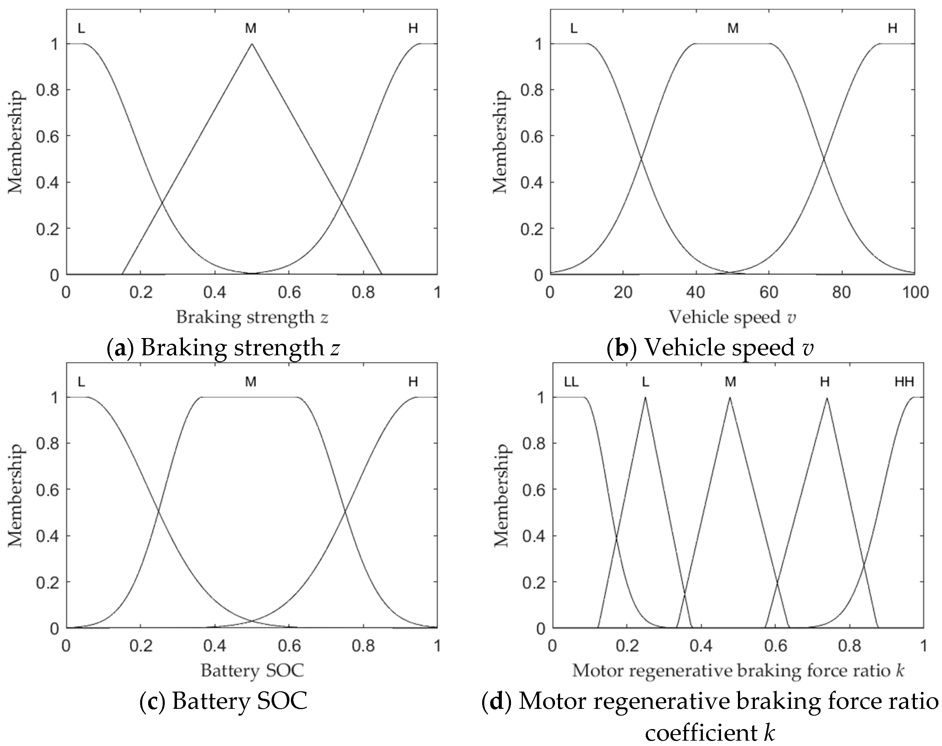
The fuzzy subset of braking strength z is {L, M, H}, and the domain is [0, 1]. The fuzzy subset of vehicle speed v is {L, M, H}, with a domain of [0, 100]. The fuzzy subset of battery SOC is {L, M, H}, with a domain of [0, 1]. The fuzzy subset of the proportional coefficient k for the regenerative braking force of the motor is {LL, L, M, H, HH}, and the domain is [0, 1]. The membership functions of braking strength z, vehicle speed v, battery SOC and motor regenerative braking force ratio coefficient k are shown in Figure 2. Based on a large number of experiments and theoretical analysis, fuzzy control rules have been formulated as shown in Table 1.

2.3. Calculation of Regenerative Braking Force for Motor

A synchronous motor has four-quadrant operating characteristics, can work as a generator when the vehicle braking, and its external characteristic curve is similar to the motor [13]. When the motor operating speed is lower than the rated speed is, the motor operating power is lower than the rated power motor regenerative braking torque determined by the rated torque of the motor, and when the motor operating speed is higher than the rated speed, the motor regenerative braking torque is determined by the rated power of the motor. From this, the mathematical model of motor regenerative braking force can be derived as follows:
F e = T e i 0 η t r , 0 < n < n e 9550 P e i 0 η t n r , n n e
In the formula, Fe is the regenerative braking torque provided by the motor; Te is the rated torque of the motor; i0 is the transmission ratio; ηt is the transmission efficiency; r is the radius of the wheel; Pe is the rated power of the motor; n is the motor speed, and ne is the rated motor speed.

2.4. Remaining Demand Braking Force Distribution

When the vehicle brakes on a long downhill slope, the motor bears the main braking force. When the required braking force of the entire vehicle is higher than the maximum braking force that the motor can provide, the remaining required braking force is provided by the friction braking force of the front and rear axles [14].
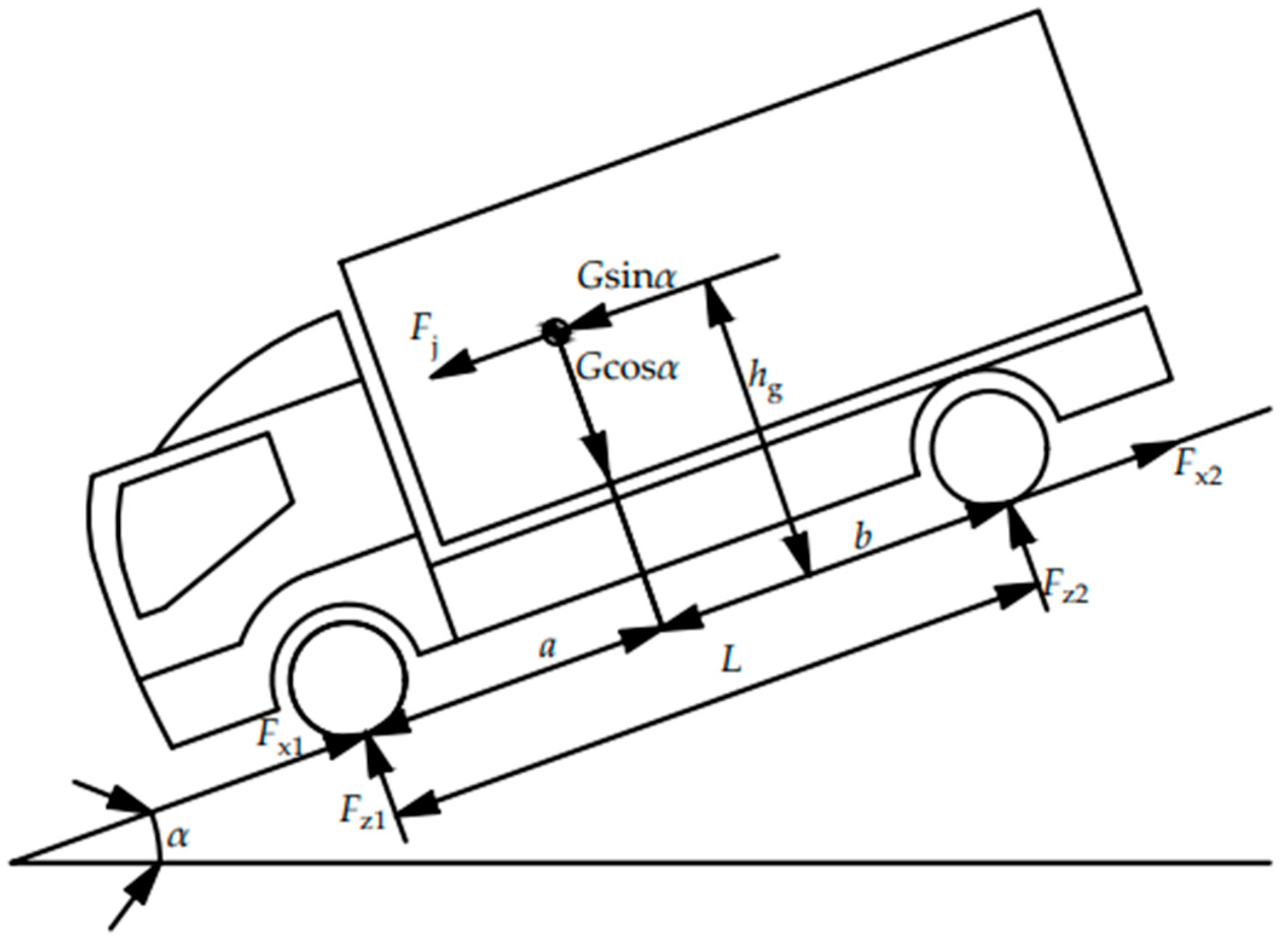
If the vehicle demand braking force is all provided by the friction braking force, at this time the vehicle overall force shown in Figure 3.
If the front- and rear-axle wheels are locked at the same time, the ground normal reaction forces Fz1 and Fz2 on the front and rear axles are as follows:
F z 1 = G [ b cos α   +   h g ( z   +   sin α ) ] L F z 2 = G [ a cos α     h g ( z   +   sin α ) ] L
The front- and rear-axle braking forces of the vehicle at this point on a long downhill road with any coefficient of adhesion are the following:
F x 1 = φ F z 1 F x 2 = φ F z 2 F x 1 + F x 2 = G φ cos α
In the formula, Fz1 is the front normal reaction force; Fz2 is the rear normal reaction force; Fx1 is the front-axle friction braking force; Fx2 is the rear-axle friction braking force; Hg is the height of the car’s center of mass; L is the distance from the front axle to the rear axle; a is the distance from the front axle to the center of mass; b is the distance from the rear axle to the center of mass; G is the vehicle’s gravity; α is the slope angle of the road; and φ is the coefficient of adhesion on the road surface.
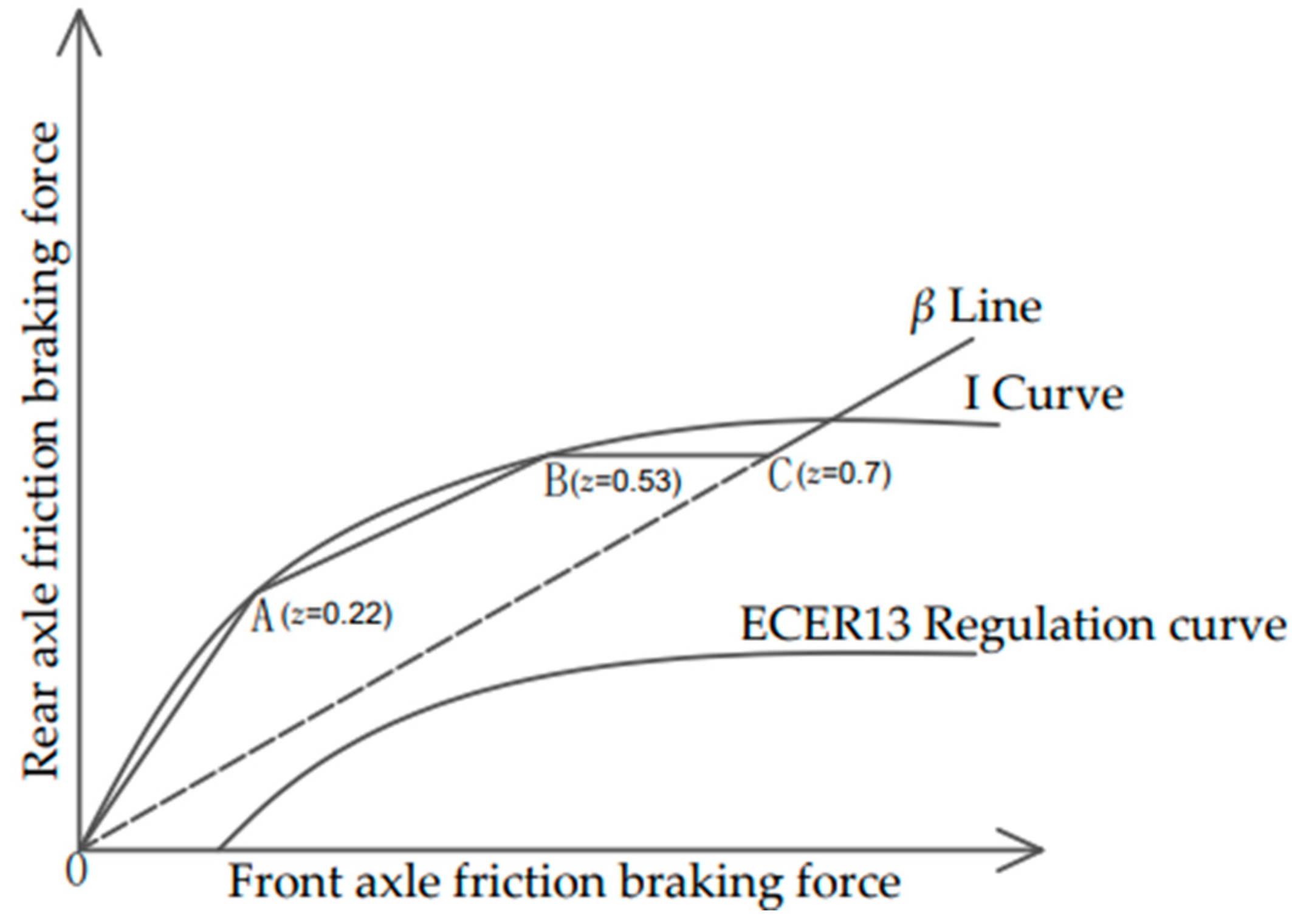
According to Equations (3) and (4), the distribution curves of front and rear axle friction braking force are drawn as shown in Figure 4.
F x 1 = z F z 1 = G z [ b cos α   +   h g ( z   +   sin α ) ] L F x 2 = z F z 2 = G z [ a cos α     h g ( z   +   sin α ) ] L
The braking strength of point A on the I curve is z = 0.22. According to Equation (5), the coordinates of point A are (Fx1A, Fx2A), and the slope of the OA line segment is KOA = Fx2A/Fx1A. Therefore, the distribution of frictional braking force on the OA line segment is as follows:
F x 1 = G z cos α 1   +   K OA F x 2 = G z cos α     F x 1
The braking strength of point B is z = 0.53. Similarly, according to Equation (5), the coordinates of point B are (Fx1B, Fx2B), and the slope of line segment AB is KAB = (Fx2BFx2A)/(Fx1BFx1A). Therefore, the distribution of frictional braking force on line segment AB is the following:
F x 1 = G z cos α 1   +   K AB + K AB F x 1 A     F x 2 A 1   +   K AB F x 2 = G z cos α F x 1
Point C is located at the β line, the braking strength z = 0.7 satisfies the following relationship:
F x 2 F x 1 = 1     β β F x 1 + F x 2 = G z cos α
In the formula, β is the distribution coefficient of friction braking force for the front and rear axles.
According to Equation (8), the coordinates of point C are (Fx1C, Fx2C), and the slope of the BC line segment is KBC = (Fx2CFx2B)/(Fx1CFx1B). Therefore, the distribution of frictional braking force on the BC line segment is as follows:
F x 1 = G z cos α 1   +   K BC + K BC F x 1 B     F x 2 B 1   +   K BC F x 2 = G z cos α F x 1
When the braking strength is z > 0.7, it belongs to emergency braking and exits the braking energy recovery mode. In order to distribute the braking force quickly and accurately to the front and rear axles, it is necessary to follow the β Line allocation:
F x 1 = G z β cos α F x 2 = G z cos α F x 1

2.5. Execution Control Constraint

In order to improve the service life of the vehicle’s power battery, when the SOC of the battery is higher than 90%, it exits the regenerative braking mode, switches to friction braking and provides all the braking power [15].
When the vehicle speed is very low, the speed of the motor is also very low, and the charging current generated is very small, which is not enough to charge the battery effectively. So in order to stop the vehicle as soon as possible, when the vehicle speed is lower than 5 km/h, it exits the regenerative braking mode and switches to friction braking and provides all the braking force [16].

3. Establish Control Strategies and Vehicle Models

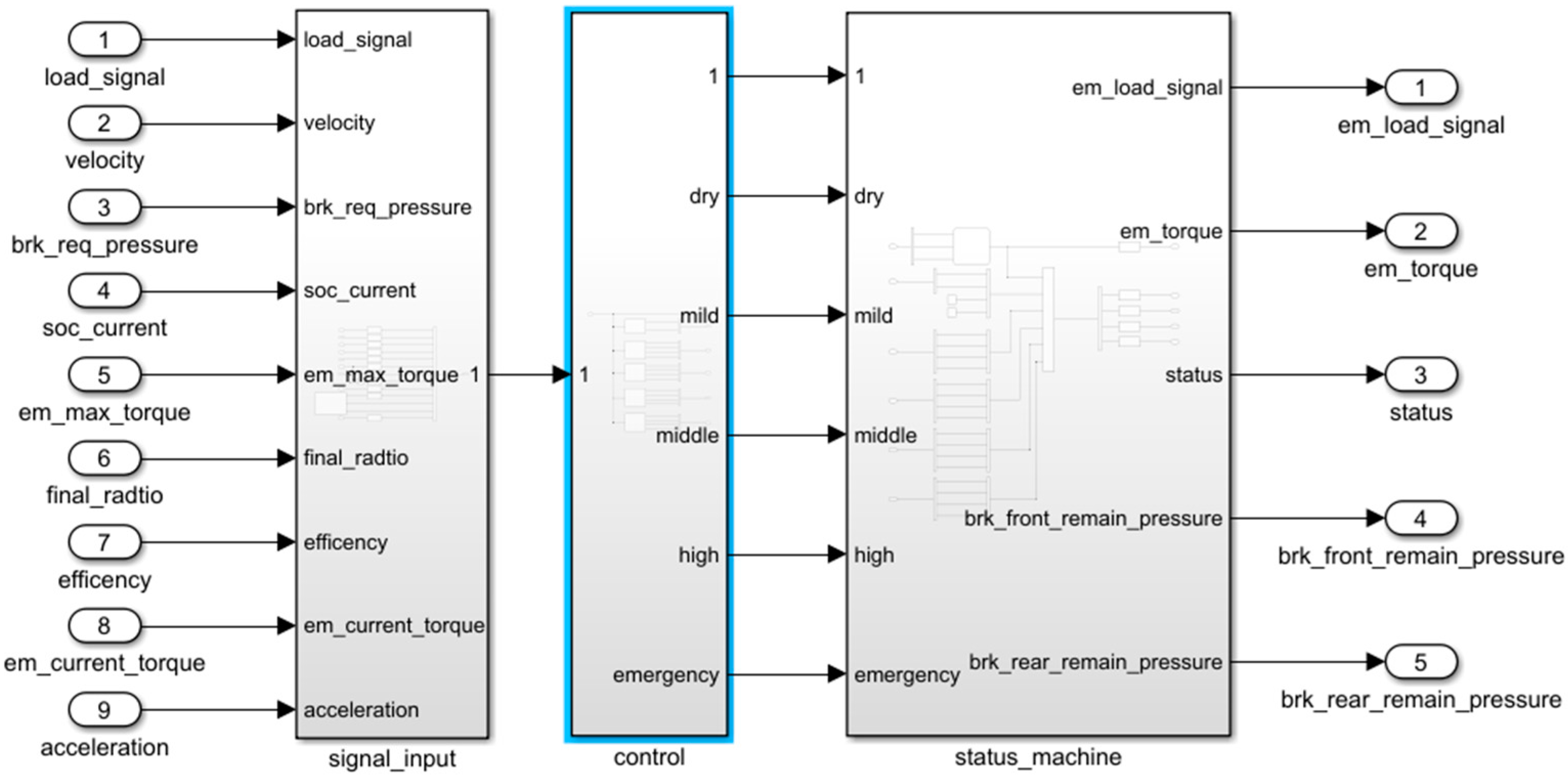
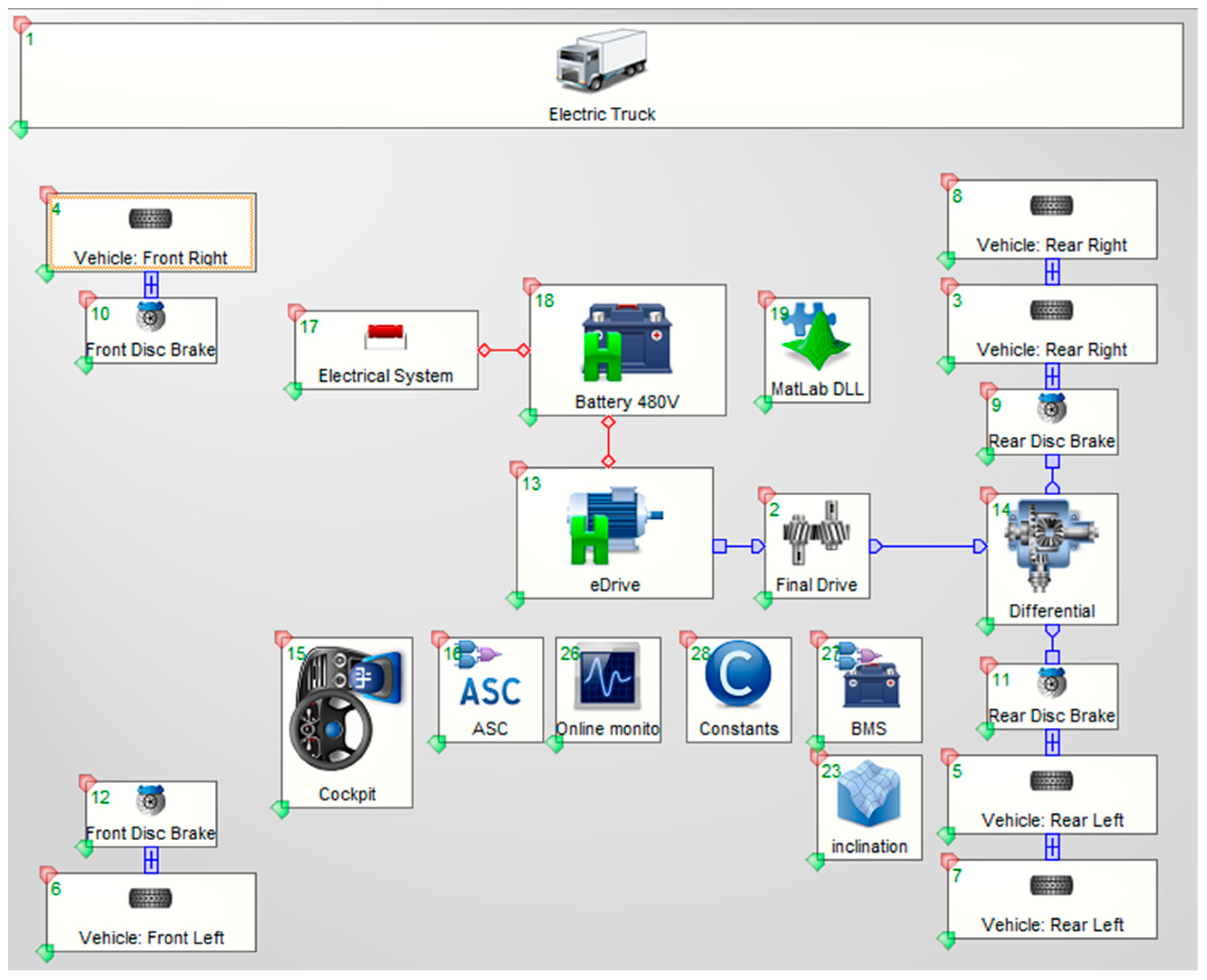
In order to verify the feasibility of the proposed control strategy and the effect of braking energy recovery, a pure electric commercial vehicle was selected [17], and the parameters of the whole vehicle are shown in Table 2. Utilize MATLAB/Simulink to build a control strategy model, as shown in Figure 5, use Cruise (R2019.2) software to build a vehicle model, use the General Map module in Cruise (R2019.2) software to set the slope of different driving sections and compile and generate DLL files written in Simulink and embed them in the vehicle model, as shown in Figure 6.

4. Results and Discussion

4.1. Analysis of Driving Conditions and Results of Fixed Slope and Long Downhill Driving

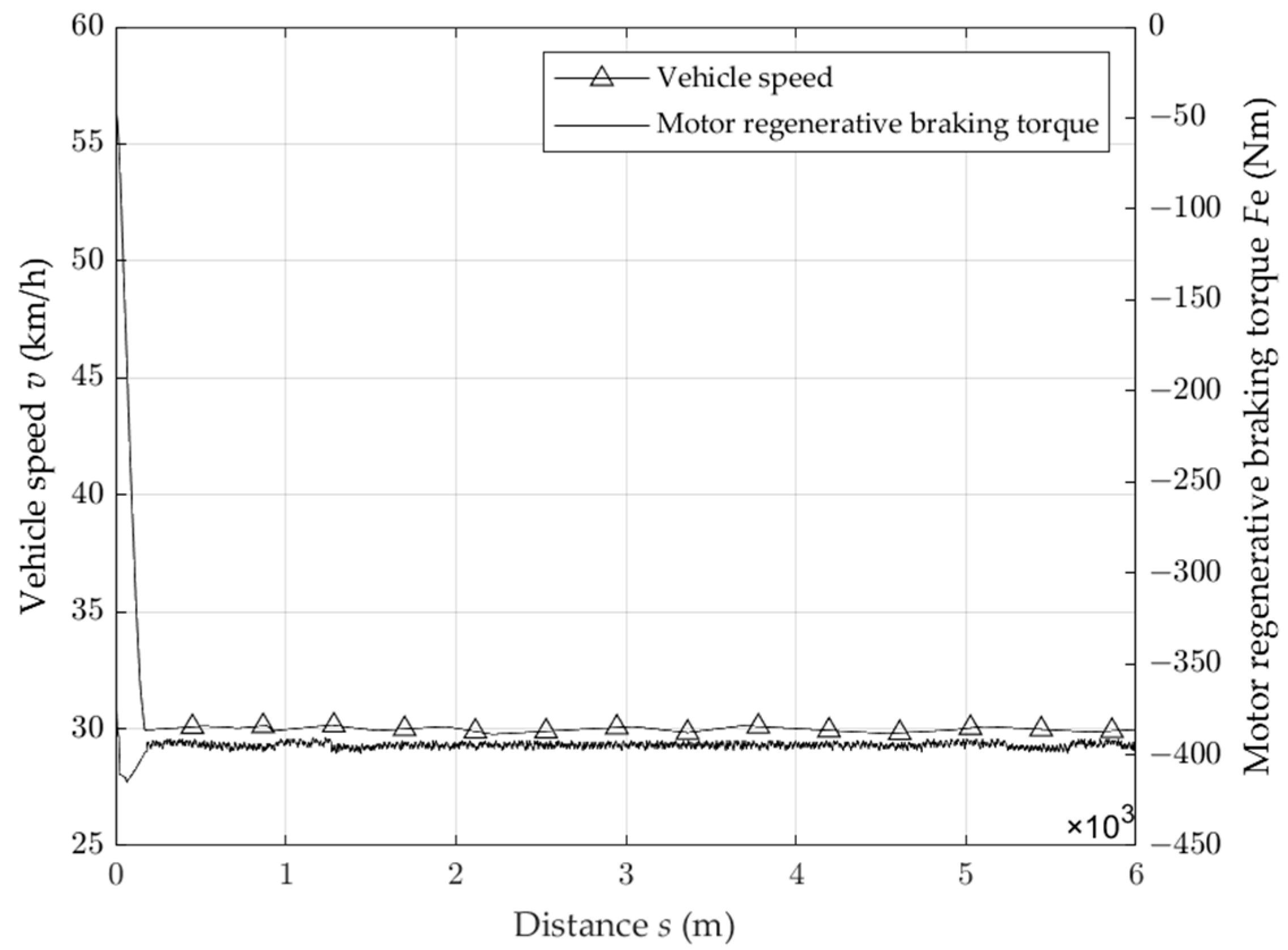
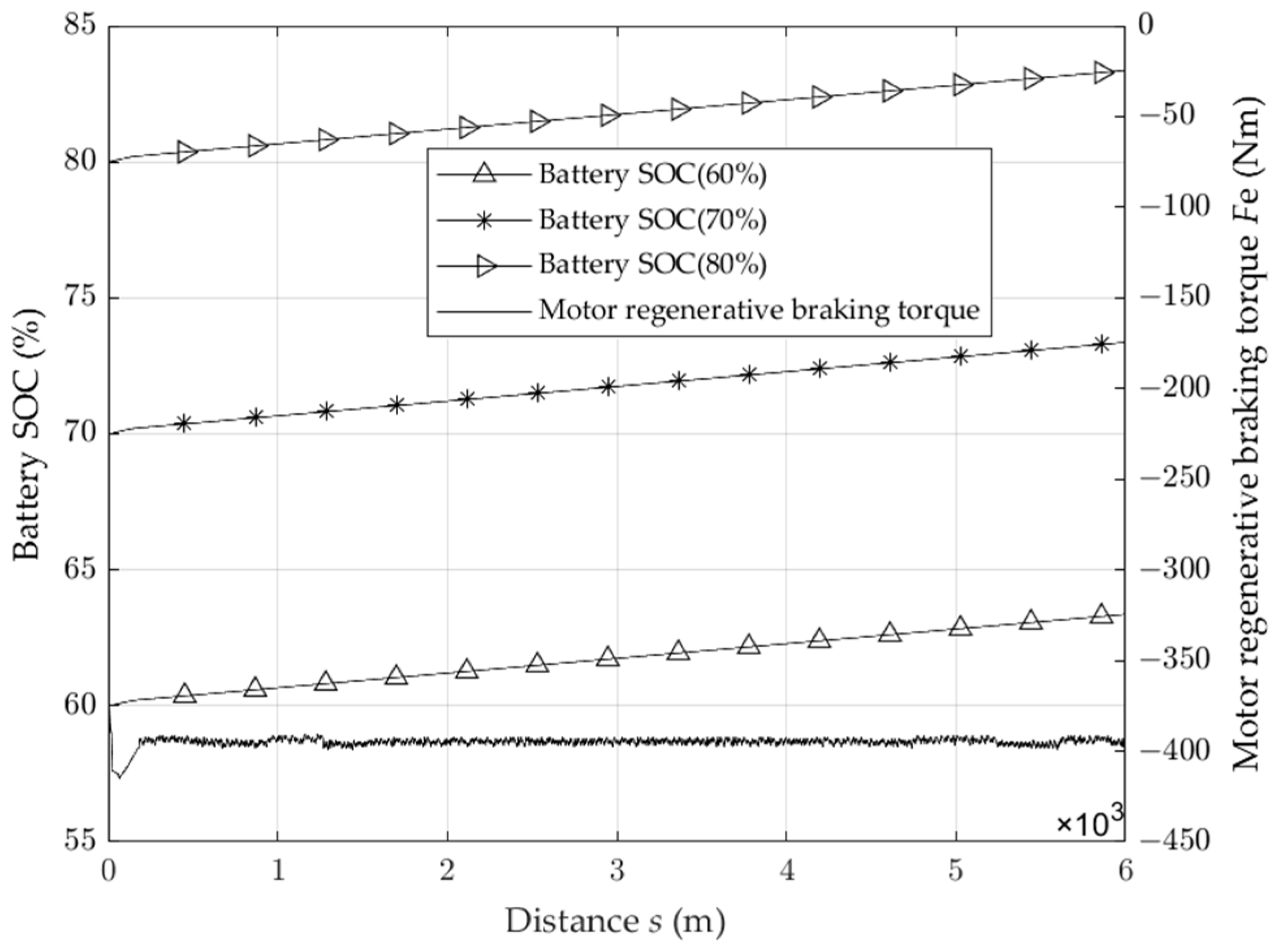
According to the requirements of the commercial vehicle braking test in GB12676-2014, the initial speed of the vehicle on a long downhill is 60 km/h, the constant speed of a long downhill is 30 km/h, the road slope is 6%, and the driving distance is 6 km. Because the different SOC values of the battery have different effects on energy recovery, the road slope and driving distance are kept unchanged, and the initial SOC values of the power battery are set to 60%, 70% and 80%, respectively. The test results are shown in Figure 7, Figure 8 and Figure 9.
As can be seen from Figure 7, when the vehicle enters the long downhill driving, the vehicle speed is reduced from 60 km/h to 30 km/h within 200 m, and then the motor regenerative braking force provides all the braking force, maintains the constant speed of the vehicle at 30 km/h and completes the long downhill driving condition of 6 km.
As can be seen from Figure 8, during the period when the vehicle speed is reduced from 60 km/h to 30 km/h, the vehicle has deceleration, the motor provides a larger regenerative braking torque, the battery SOC rises rapidly, the motor regenerative braking torque tends to be stable after the vehicle speed is stable, and the battery SOC basically rises linearly steadily, from the initial 60% to 63.3%, from the initial 70% to 73.15% and from the initial 80% to 82.98%. When the initial value of battery SOC is 60%, the braking energy recovery rate reaches 50.93%, when the initial value of battery SOC is 70%, the braking energy recovery rate reaches 50.89%, and when the initial value of battery SOC is 80%, the braking energy recovery rate reaches 50.81%. With the increase in the initial SOC value of the battery, the braking energy recovery rate decreases because when the battery SOC value is high, the charging rate will decrease when the battery SOC value is lower. As a result, the recuperation rate of braking energy is reduced.
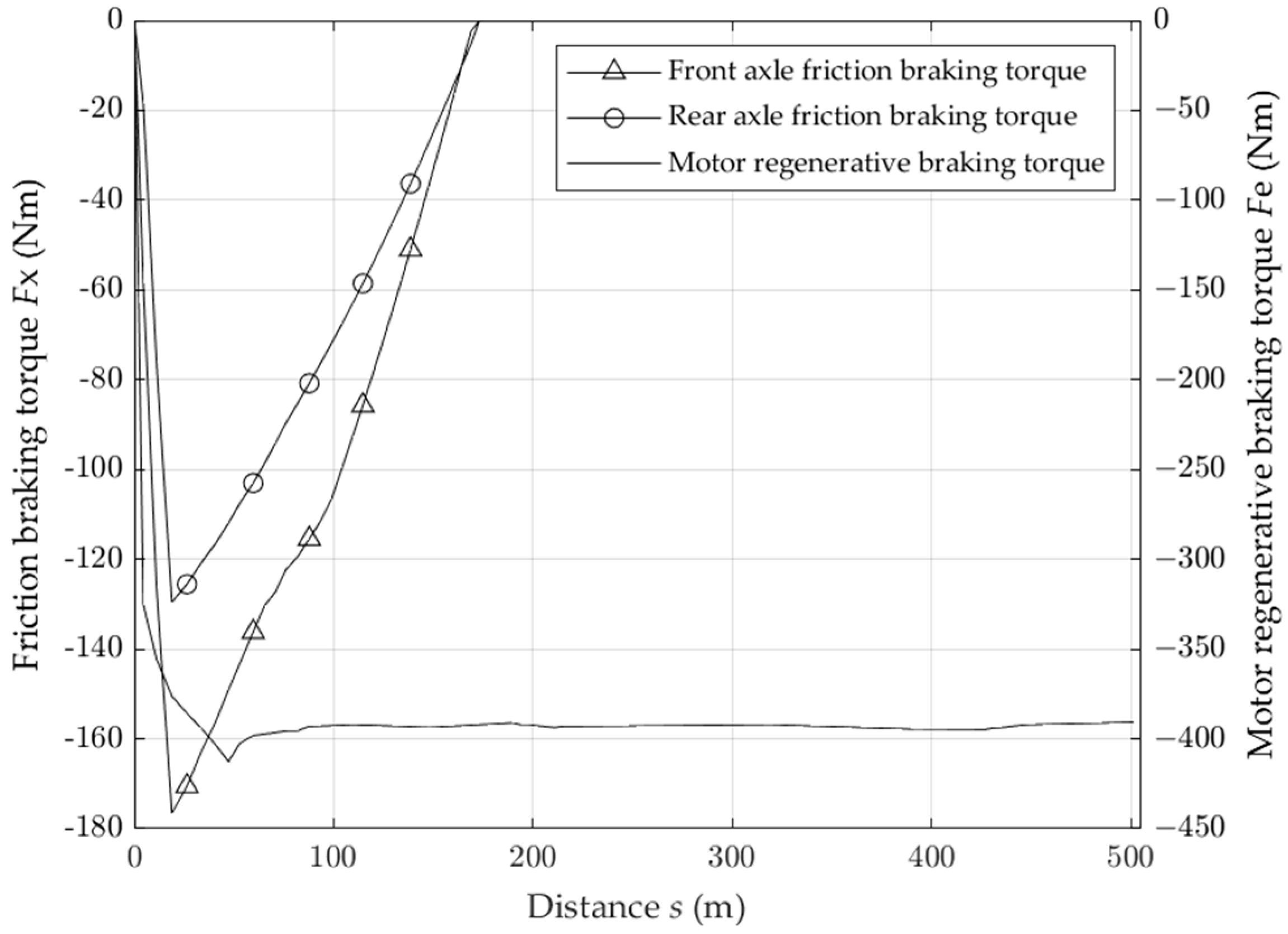
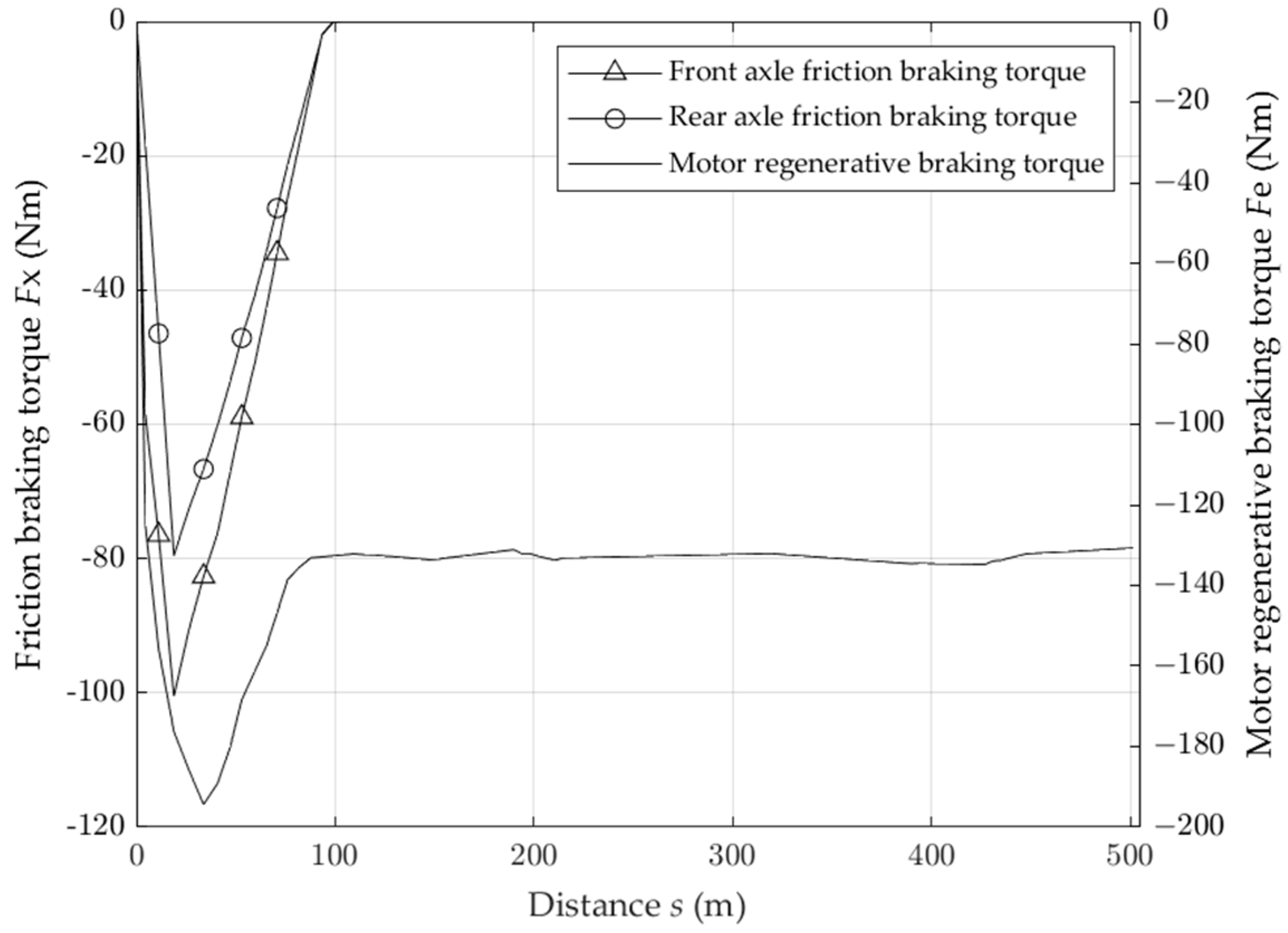
In the process of downhill driving at a constant speed of 30 km/h, the frictional braking torque is always zero, and the data of the first 500 m driving distance are selected in Figure 9 to plot the change of frictional braking torque. At the beginning of the test, as the driver presses the brake pedal, the friction braking torque and the motor regeneration braking torque rise rapidly, as the vehicle speed decreases, the driver relaxes the brake pedal, the friction braking torque gradually decreases to zero, and no longer participates in braking, and the motor bears all the braking torque at the same time.

4.2. Analysis of Driving Conditions and Results of Variable Slope and Long Downhill Driving

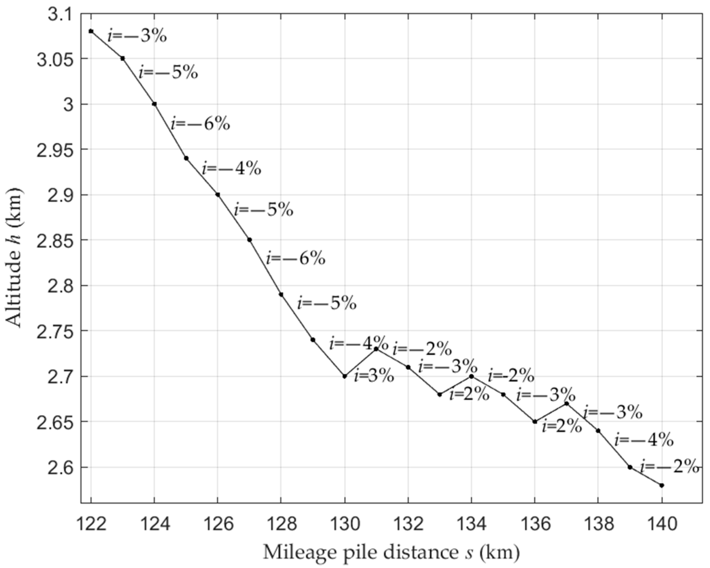
The 18 km long road in the 122 km~140 km mileage section of National Highway 318 was selected as the test road condition, and the 2% downhill distance in the road section was 3 km, the 3% downhill distance was 4 km, the 4% downhill distance was 3 km, the 5% downhill distance was 3 km, the 6% downhill distance was 2 km, the 2% uphill distance was 2 km, and the 3% uphill distance was 1 km. The road slope information is shown in Figure 10. The initial speed of the vehicle is set to 60 km/h, and the initial SOC value of the power battery is set to 60% [18]. Test results are shown in Figure 11, Figure 12 and Figure 13.
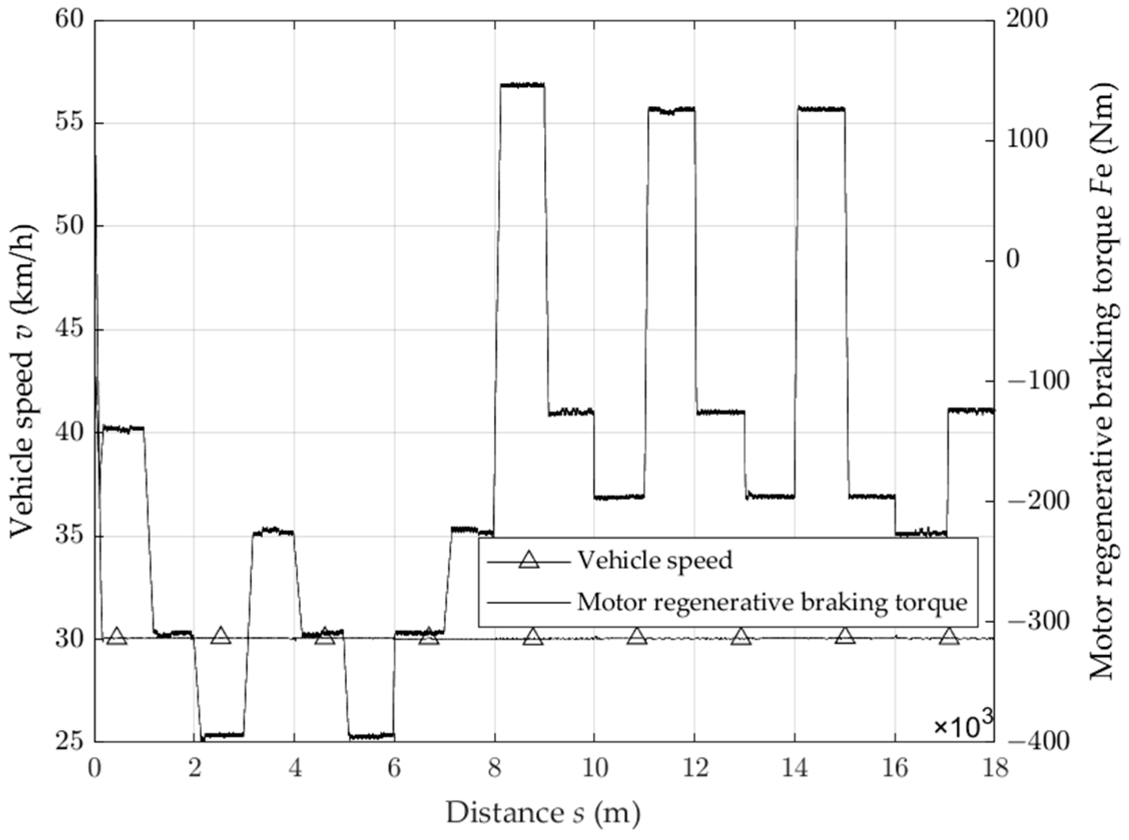
As can be seen in Figure 11, when the vehicle enters a long downhill drive, the vehicle speed is still reduced from 60 km/h to 30 km/h within 200 m. Since the gradient of the beginning section of the road is 3%, the motor provides a small regenerative braking torque to keep the vehicle driving at 30 km/h. When the vehicle enters different gradient sections, the speed of the vehicle fluctuates slightly because the regenerative braking torque of the motor cannot be increased or decreased instantaneously. At the same time, the regenerative braking torque of the motor is also adjusted accordingly with the change of the road gradient, which can keep the vehicle traveling downhill at a constant speed of 30 km/h.
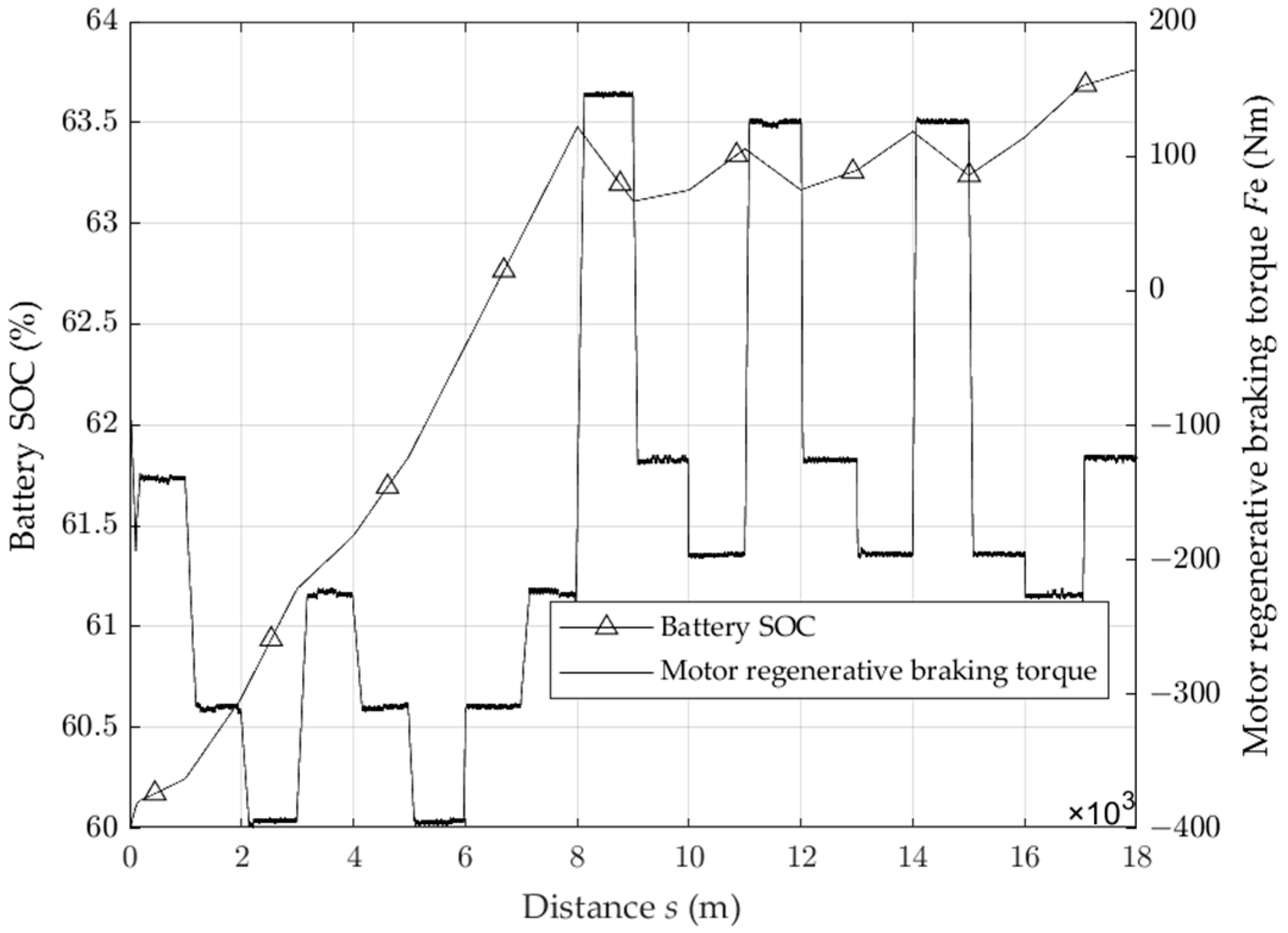
As can be seen in Figure 12, the first 6 km are all downhill sections, and after the vehicle speed is stabilized, the battery SOC are all basically rising at a uniform rate. When driving into the uphill section, the motor drives the vehicle in order to enter the downhill section again, without friction braking to reduce the vehicle speed and still maintaining the speed of 30 km/h driving, which can reduce energy consumption. When the vehicle is traveling on the same slope section, the regenerative braking torque provided by the motor is basically equal. The growth rate of the battery SOC is determined by the road gradient and the size of the regenerative braking torque; when the road gradient is larger, the motor needs to provide a larger torque, and the growth rate of the battery SOC is also increased. When the road gradient is small, the motor only needs to provide a smaller torque, and the growth rate of the battery SOC decreases. After the vehicle has traveled the 18 km section, the battery SOC value increases from 60% to 63.75%, and the braking energy recovery rate reaches 49.96%.
As can be seen from Figure 13, the friction braking torque and the regenerative braking torque provided by the motor are smaller than those in Figure 9 because the gradient of the road that the vehicle starts to enter are smaller, so the ramp force to which the vehicle is subjected decreases, the braking torque demanded by the whole vehicle decreases, and the deceleration distance required decreases accordingly, but the overall trend of change in braking force remains unchanged.

5. Conclusions

When pure electric commercial vehicles brake on long downhill slopes, the braking load rapidly increases, and the brakes are prone to thermal degradation. Based on the braking strength and the fuzzy control method, a braking force distribution strategy is designed. The following conclusions are drawn from the results of the long downhill driving condition:
(1)
Under the condition of constant slope driving, the motor provides continuous braking so that the vehicle can maintain a constant speed of 30 km/h downhill driving, and the braking energy recovery rate reaches 50.93% under the initial 60% battery SOC. The braking energy recovery rate reaches 50.89% under the initial 70% battery SOC, and the braking energy recovery rate reaches 50.81% under the initial 80% battery SOC. It is concluded that when the battery SOC reaches 80%, the braking energy recovery rate will decrease, and in order to improve the battery service life, the braking energy recovery will be stopped when the battery SOC reaches 90%;
(2)
Under the condition of variable slope driving, the motor regenerative braking torque is determined by the size of the road slope: when the slope changes, the regenerative braking torque decreases, and the braking energy recovery speed decreases. When the slope increases, the regenerative braking torque increases, and the braking energy recovery speed increases. At the same time, after adjusting the power torque of the electric mechanism, the vehicle can still be kept at a constant speed of 30 km/h, and the braking energy recovery rate reaches 49.96%;
(3)
When the vehicle is kept at a constant driving speed of 30 km/h, the friction braking force is no longer involved in braking, which can effectively prevent the brake from generating thermal degradation phenomenon and improve the braking stability of the vehicle;
(4)
The continuous braking joint control strategy for pure electric commercial vehicles mentioned in the introduction mainly utilizes the electric motor to take part of the auxiliary braking to reduce the temperature of the retarder, and the main continuous braking part is still provided by the retarder. Compared with this paper, it is more complicated in structure and the braking energy recovery rate is not very high. The use of motor anti-drag characteristics for sustained braking is theoretically possible; there are authors using simulation to verify this, but in the case of high battery SOC for sustained braking is still lacking. In order to avoid overcharging the battery and still need the motor for sustained braking, the vehicle will inevitably need to be retrofitted with other energy storage devices or direct energy directly provided to the vehicle’s horn, air conditioning and other equipment.

Author Contributions

Investigation, W.C. and C.L.; methodology, W.C. and C.L.; software, W.C.; resources, C.L.; writing—original draft, W.C.; writing—review and editing, W.C. and C.L. All authors have read and agreed to the published version of the manuscript.

Funding

This research was funded by National Natural Science Foundation of China (Grant No. 11802108).

Data Availability Statement

The experimental data are contained within the article.

Conflicts of Interest

The authors declare no conflicts of interest.

References

  1. Wager, G.; Whale, J.; Braunl, T. Performance Evaluation of Regenerative Braking Systems. Proc. Inst. Mech. Eng. Part D J. Automob. Eng. 2018, 232, 1414–1427. [Google Scholar] [CrossRef]
  2. Ni, C.; Gao, H.; Kong, F. Design of downhill travel assist braking system for electric trucks. Light Veh. Technol. 2019, 3–4, 12. [Google Scholar]
  3. Lan, H.; Ma, Z.; Li, X. Long downhill joint braking control strategy for electric commercial vehicles based on dynamic planning. J. Northwest Univ. Nat. Sci. Ed. 2020, 50, 987–995. [Google Scholar]
  4. Chang, J.; Zhang, Y. Research on optimal control strategy of braking energy recovery for pure electric vehicles based on EMB. Automot. Eng. 2022, 44, 64–72. [Google Scholar]
  5. Shi, P.; Gao, Y.; Zhang, Z. Recognition of long downhill braking conditions of heavy-duty trucks. J. Automot. Saf. Energy Conserv. 2023, 14, 299–309. [Google Scholar]
  6. Yabe, T.; Akatsu, K.; Okui, N.; Niikuni, T.; Kawai, T. Efficiency Improvement of Regenerative Energy for an EV. World Electr. Veh. J. 2012, 5, 494–500. [Google Scholar] [CrossRef]
  7. Zhang, W.; Yang, J.; Zhang, W.; Ma, F. Research on Regenerative Braking of Pure Electric Mining Dump Truck. World Electr. Veh. J. 2019, 10, 39. [Google Scholar] [CrossRef]
  8. Li, Z.; Shi, Z.; Gao, J.; Xi, J. Research on Regenerative Braking Control Strategy for Single-Pedal Pure Electric Commercial Vehicles. World Electr. Veh. J. 2023, 14, 229. [Google Scholar] [CrossRef]
  9. Wei, L. Research on Long Downhill Composite Braking Control Strategy and Braking Energy Recovery for Pure Electric Commercial Vehicles. Master’s Thesis, Chang’an University, Xi’an, China, 2021. [Google Scholar]
  10. Trovão, J.P.; Santos, V.D.N.; Pereirinha, P.G.; Jorge, H.M.; Antunes, C.H. Comparative Study of Different Energy Management Strategies for Dual-Source Electric Vehicles. World Electr. Veh. J. 2013, 6, 523–531. [Google Scholar] [CrossRef]
  11. Miri, I.; Fotouhi, A.; Ewin, N. Electric Vehicle Energy Consumption Modelling and Estimation—A Case Study. Int. J. Energy Res. 2021, 45, 501–520. [Google Scholar] [CrossRef]
  12. Khanra, M.; Chakraborty, D.; Nandi, A.K. Improvement of Regenerative Braking Energy of Fully Battery Electric Vehicle through Optimal Driving. J. Asian Electr. Veh. 2018, 16, 1789–1798. [Google Scholar] [CrossRef]
  13. Yu, Y.; Jiang, J.; Min, Z.; Wang, P.; Shen, W. Research on Energy Management Strategies of Extended-Range Electric Vehicles Based on Driving Characteristics. World Electr. Veh. J. 2020, 11, 54. [Google Scholar] [CrossRef]
  14. Krishnamoorthy, K.; Pazhamalai, P.; Mariappan, V.K.; Manoharan, S.; Kesavan, D.; Kim, S. Two-Dimensional Siloxene–Graphene Heterostructure-Based High-Performance Supercapacitor for Capturing Regenerative Braking Energy in Electric Vehicles. Adv. Funct. Mater. 2021, 31, 2008422. [Google Scholar] [CrossRef]
  15. Chen, B.; Evangelou, S.A.; Lot, R. Series Hybrid Electric Vehicle Simultaneous Energy Management and Driving Speed Optimization. IEEE/ASME Trans. Mechatron. 2019, 24, 2756–2767. [Google Scholar] [CrossRef]
  16. Zhao, L.; Cao, Q.; Li, Y.; Gao, N. An Optimization Technique of Braking Force Distribution Coefficient for Truck. In Proceedings of the Proceedings 2011 International Conference on Transportation, Mechanical, and Electrical Engineering (TMEE), Changchun, China, 16–18 December 2011; IEEE: Piscataway, NJ, USA, 2011; pp. 1784–1787. [Google Scholar]
  17. Goodarzi, A.; Mehrmashhadi, J.; Esmailzadeh, E. Optimised Braking Force Distribution Strategies for Straight and Curved Braking. Int. J. Heavy Veh. Syst. 2009, 16, 78. [Google Scholar] [CrossRef]
  18. Xu, J.; Zhang, X. Optimization Algorithm for Vehicle Braking Force Distribution of Front and Rear Axles Based on Brake Strength. In Proceedings of the 2016 12th World Congress on Intelligent Control and Automation (WCICA), Guilin, China, 12–15 June 2016; IEEE: Piscataway, NJ, USA; pp. 3353–3360. [Google Scholar]
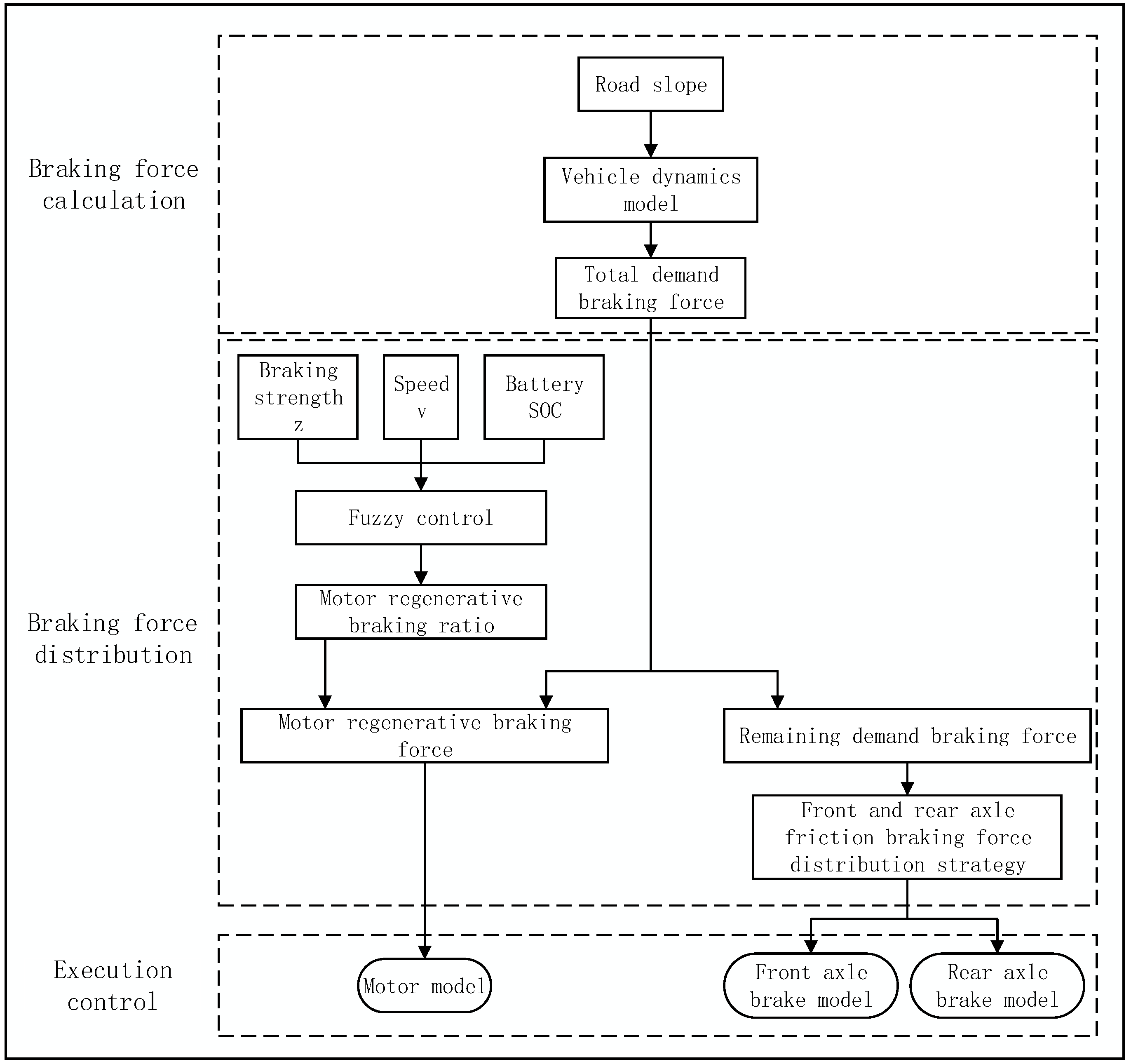
Figure 1. Long downhill braking control strategy.
Wevj 15 00051 g001
Figure 2. (a) The membership functions of braking strength z; (b) the membership functions of vehicle speed v; (c) the membership functions of battery SOC; (d) the membership functions of motor regenerative braking force ratio coefficient k.
Wevj 15 00051 g002
Figure 3. Analysis of vehicle downhill braking forces.
Wevj 15 00051 g003
Figure 4. Front- and rear-axle friction braking force distribution curve.
Wevj 15 00051 g004
Figure 5. Control strategy model.
Wevj 15 00051 g005
Figure 6. Vehicle model.
Wevj 15 00051 g006
Figure 7. Vehicle speed and motor regenerative braking torque under constant gradient conditions.
Wevj 15 00051 g007
Figure 8. Battery SOC and motor regenerative braking torque under constant gradient conditions.
Wevj 15 00051 g008
Figure 9. Front- and rear-axle friction braking torque and motor regenerative braking torque under constant gradient conditions.
Wevj 15 00051 g009
Figure 10. Road slope.
Wevj 15 00051 g010
Figure 11. Vehicle speed and motor regenerative braking torque under variable gradient conditions.
Wevj 15 00051 g011
Figure 12. Battery SOC and motor regenerative braking torque under variable gradient conditions.
Wevj 15 00051 g012
Figure 13. Front- and rear-axle friction braking torque and motor regenerative braking torque under variable gradient conditions.
Wevj 15 00051 g013
Table 1. Fuzzy control rules.
NumberzvSOCk
1LLLHH
2MLLH
3HLLM
4LMLH
5MMLM
6HMLL
7LHLM
8MHLL
9HHLLL
10LLMHH
11MLMH
12HLMM
13LMMH
14MMMM
15HMML
16LHMM
17MHML
18HHMLL
19LLHL
20MLHL
21HLHLL
22LMHL
23MMHL
24HMHLL
25LHHL
26MHHL
27HHHLL
Table 2. Vehicle parameters.
ParameterValueParameterValue
Vehicle curb weight m/t3.05Rolling resistance coefficient f0.08
Vehicle full weight m1/t6.15Main reducer reduction ratio i07.05
Vehicle test mass m2/t4.05transmission efficiency ηt0.95
Wheelbase L/m4.96Motor peak power pm/kw320
Distance from front axle to center of mass a/m2.05Motor peak torque Tm/N·m500
Distance from rear axle to center of mass b/m2.91Rated power of motor pe/kw250
Centroid height hg/m0.94Rated torque of motor Te/N·m420
Windward area A/m25.3Maximum battery voltage U/V480
Drag coefficient CD0.67Minimum battery voltage U/V400
Wheel radius r/mm515Number of battery packs8
Disclaimer/Publisher’s Note: The statements, opinions and data contained in all publications are solely those of the individual author(s) and contributor(s) and not of MDPI and/or the editor(s). MDPI and/or the editor(s) disclaim responsibility for any injury to people or property resulting from any ideas, methods, instructions or products referred to in the content.