Article

Analysis and Design Considerations for Transmitter-Compensated Inductance Mistuning in a WPT System with LCC-S Topology

1
Energy Research Institute of Shandong Academy of Sciences, Qilu University of Technology (Shandong Academy of Sciences), Jinan 250014, China
2
School of Intelligent Manufacturing, Shandong Technician Institute, Jinan 250200, China
3
School of Electrical Engineering, Shandong University, Jinan 250061, China
*
Author to whom correspondence should be addressed.
These authors contributed equally to this work.
World Electr. Veh. J. 2024, 15(2), 45; https://doi.org/10.3390/wevj15020045
Submission received: 14 December 2023 / Revised: 14 January 2024 / Accepted: 24 January 2024 / Published: 31 January 2024

Abstract

:
In this paper, theoretical analysis and system simulations are carried out to study the effects of the transmitter-compensated inductance mistuning on charging power, transfer efficiency, and the phase angle between the input voltage and input current in a wireless power transfer (WPT) system using inductor/capacitor/capacitor-series (LCC-S) topology. To cancel out the effects of the mistuning, an integrated transmitting coil design scheme is proposed, in which the transmitting coil is unipolar while the compensation coils are bipolar. Theoretical calculations and simulations are performed to show that the proposed compensation inductor guarantees the stability of the compensation inductance when the permeability of the magnetic sheet changes. Furthermore, it is verified that by using the integrated structure the effect of the horizontal misalignment can be ignored. Finally, an experimental platform is built to validate the above results of theoretical analysis and simulation. This proves that the theoretical analysis and simulation results are consistent with each other, which confirmed the stability and feasibility of the integrated compensation inductor.

1. Introduction

Over 100 years ago, Nikola Tesla first proposed the concept of wireless power transfer (WPT) technology [1]. However, it was not until the magnetically coupled resonant wireless power transfer (MCR-WPT) technology was put forward by Soljacic in 2007 that the WPT system could operate economically enough to be used as a commercial product. Nowadays, MCR-WPT technology is widely used in devices’ power supplies, such as EVs charging [2,3,4,5], materials handling [6,7,8], and so on. Because there is no exposed electric connector, the WPT system can be applied to power systems in the mine or underwater [9], which can help to decrease the risk of electric spark excitation and shorting out [10,11,12,13,14].
In a general MCR-WPT system, power is transferred over a reasonably large air gap (1–15 cm) between the transmitting coil and receiving coil [15]. In order to tune the two coils working at the same frequency in a variety of applications, scholars have proposed different compensation topologies. According to how the compensation capacitors are added to the transmitting and receiving coils, the basic compensation topologies can be divided into four categories, which are series–series (SS) [16], series–parallel (SP) [17], parallel–series (PS) [18], and parallel–parallel (PP) [19]. At present, in addition to the above four basic compensation networks, the researchers also proposed the inductor/capacitor/capacitor (LCC) compensation network. The application of the LCC compensation network promotes the development of static charging to dynamic charging in the WPT system [20], and improves the flexibility of the WPT system.
The battery chargers for automatic guided vehicles need constant frequency control to reduce electromagnetic interference (EMI) and interference to IF broadcasting under full operating conditions. We need a relatively constant and load-independent transmitting current to realize closed-loop control of the output current/voltage separately at the receiving end. To realize constant power and high efficiency, we also needed minimized switching losses. To meet the above needs, many researchers have chosen the inductor/capacitor/capacitor-series (LCC-S) compensation network, in which the transmitting terminal provides LCC compensation and the receiving terminal provides series compensation. By utilizing the LCC-S compensation, the resonant converter delivers rated power to a nominal load at a predefined constant resonant frequency. The primary side current is loaded independently to guarantee constant power delivery, and a zero-voltage switching (ZVS) condition can be achieved by adjusting the compensation structure parameters to minimize switching losses [21,22].
The compensation inductance at the transmitting side is a key factor of the entire system as constant compensation inductance can help to achieve ZVS and maintain constant output power of the system. To maintain the stability of the parameter of the transmitter-compensated inductor, the use of an air-core inductor is an optimal solution [1,23]. However, the air-core inductor has fatal defects such as a large volume and large magnetic leakage, and it is inconvenient to install. To solve the problems of air-core inductors, many researchers use inductors with magnetic cores to reduce the volume while achieving magnetic shielding [24], but the value of the compensation inductance is assumed to be constant. Nevertheless, due to changes in ambient temperature and magnetic field strength in practical applications, the permeability of a magnetic-core is not a fixed value, which shows that it is difficult to maintain a constant resonant inductance [25]. Once the resonant compensation inductance changes, the circuit is in a non-resonance state and the output power of the system will not reach the rated power of the charging device, resulting in an extended charging time. Another problem more serious than this is that the system may enter into a zero-current switching (ZCS) condition, causing a large shock or even damaging the components. Therefore, maintaining the stability of the LCC resonant circuit is key to achieving constant output power through wireless transmission.
In previous research, few scholars have systematically analyzed the influence of transmitter-compensated inductance mistuning in the LCC-S topology of a WPT system, let alone investigated how to reduce the offset of compensation inductance. In view of the above problem, we carried out a series of analyses and research on transmitter-compensated inductance mistuning in the LCC-S topology.
The paper is structured as follows: in Section 2, firstly, the instability characteristics of commonly used magnetic-core compensation inductors are proposed, then their effects on the system output power, transfer efficiency, and the phase shift angle between the input voltage and input current in a wireless power transfer (WPT) system using inductor/capacitor/capacitor-series (LCC-S) topology are analyzed and simulated. The design solutions and analysis between the proposed integrated inductor coil and transmitting coil and receiving coil are given in Section 3, and simulation platforms are built to prove the validity of the strategy. In Section 4, an experimental platform is fabricated, and a comparative analysis between the experimental, simulation, and theoretical results is made. Finally, conclusions are presented.

2. Detailed Analysis and Simulations for Instability of Commonly Used Compensation Inductor

In an LCC-S WPT system, usually there are two options while designing compensation inductors, i.e., a magnetic-core inductor and an air-core inductor. In the air-core and magnetic-core inductor design, the inductor is separated from the transmitting coil and receiving coil. Air-core inductors have the advantages of strong resistance to large current impact and saturation, but they require a large mounting area, and another issue is the occurrence of EMI and external radiation. Magnetic-core inductors are constructed of ferrite cores and coils, and the ferrite used in this experiment is PC40. For the magnetic-core inductor, the magnetic fields inside the ferrite can be confined and compared to the air-core, and they require a small area. However, when the system is operating, the heat generated by the coil current will change the ambient temperature, which will alter the temperature of the magnetic core. This change in the temperature will lead to altering the permeability of the magnetic material PC40 compensation inductor, which eventually changes the inductance [25]. The specific relationship between the permeability of the magnetic material and the value of inductance has been introduced in the TDK magnetic materials manual (Mn–Zn Ferrite Material characteristics) [26]. Consequently, the system will not be in resonance anymore and the output power of the system will decrease. From the following theoretical analysis of the effect of the change in compensation inductor on the system output power, the transfer efficiency and the phase shift angle between the input voltage and input current are calculated.

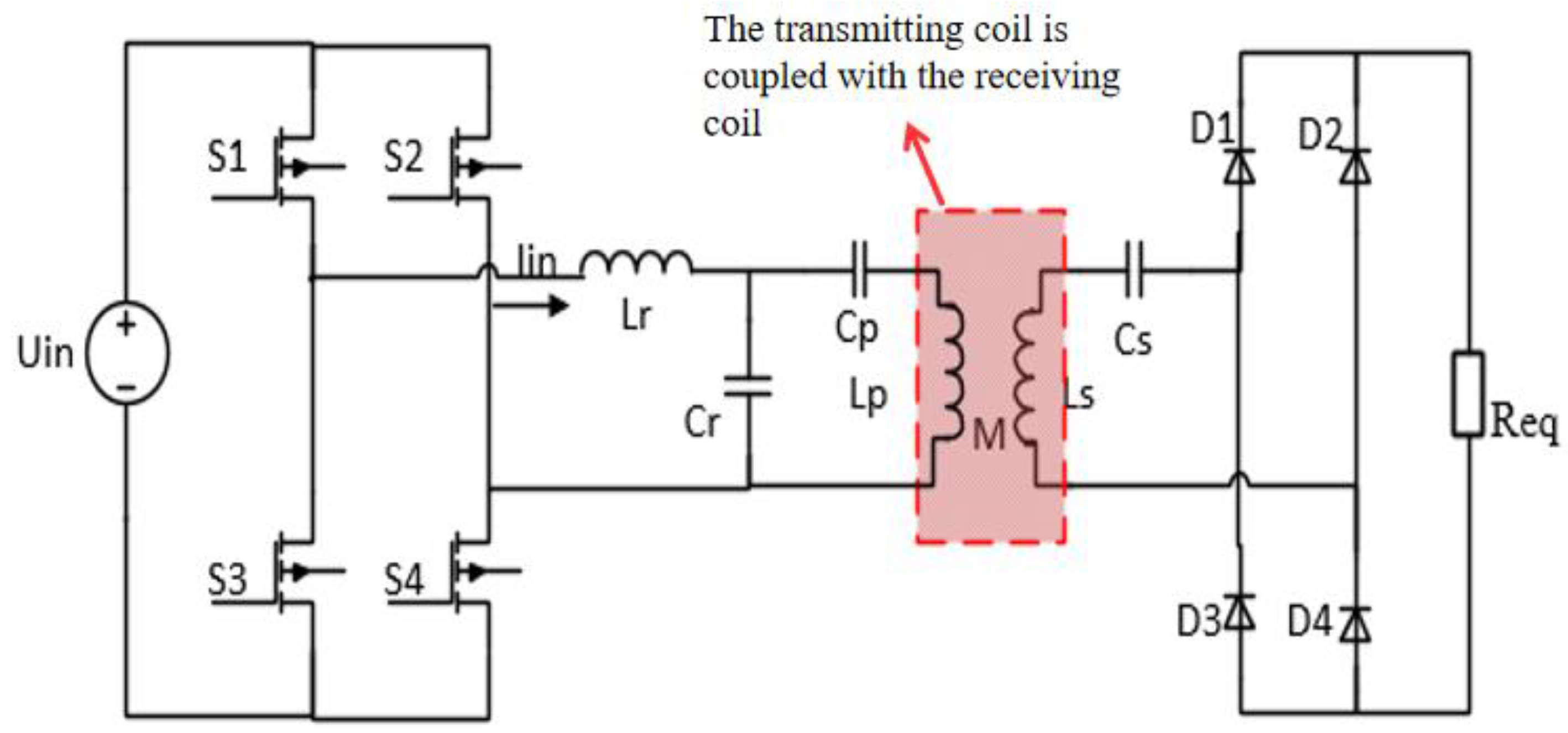
2.1. Fundamentals of WPT System with Commonly Used LCC-S Topology

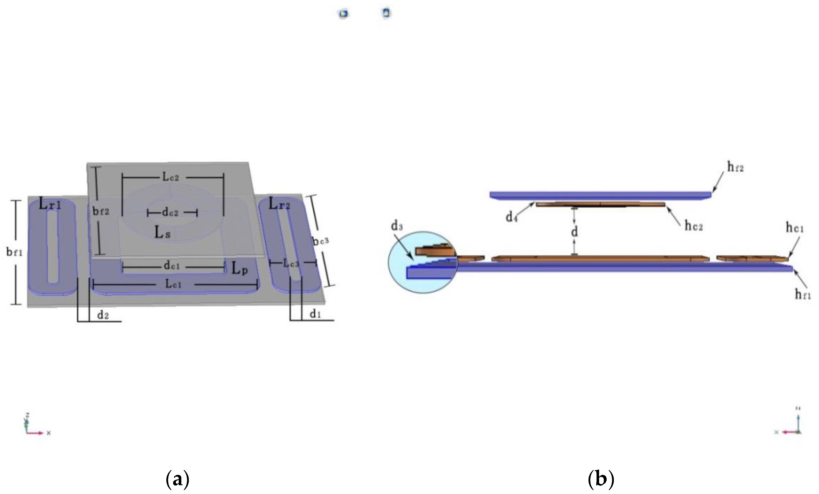
2.1.1. Coupler Structure and Elements

The circuit topology of a conventional LCC-compensated single-coupled WPT system is shown in Figure 1. At the transmitter side, a DC voltage source Uin is used as the power supply, and the compensation topology consists of two capacitors and one inductor together with the main coil, in which capacitors Cr and Cp are used to resonate with Lr and Lp, respectively. Meanwhile, at the receiver side, the receiver coil Ls is in series with the capacitor Cs. Furthermore, an uncontrolled diode rectifier is accepted to provide DC voltage to load. In this topology, it should be pointed out that the compensation inductance Lr and the transmitting coil Lp are not integrated together at the primary side, and the only coupling in the system is in between the transmitting coil and the receiving coil, which is expressed as M.

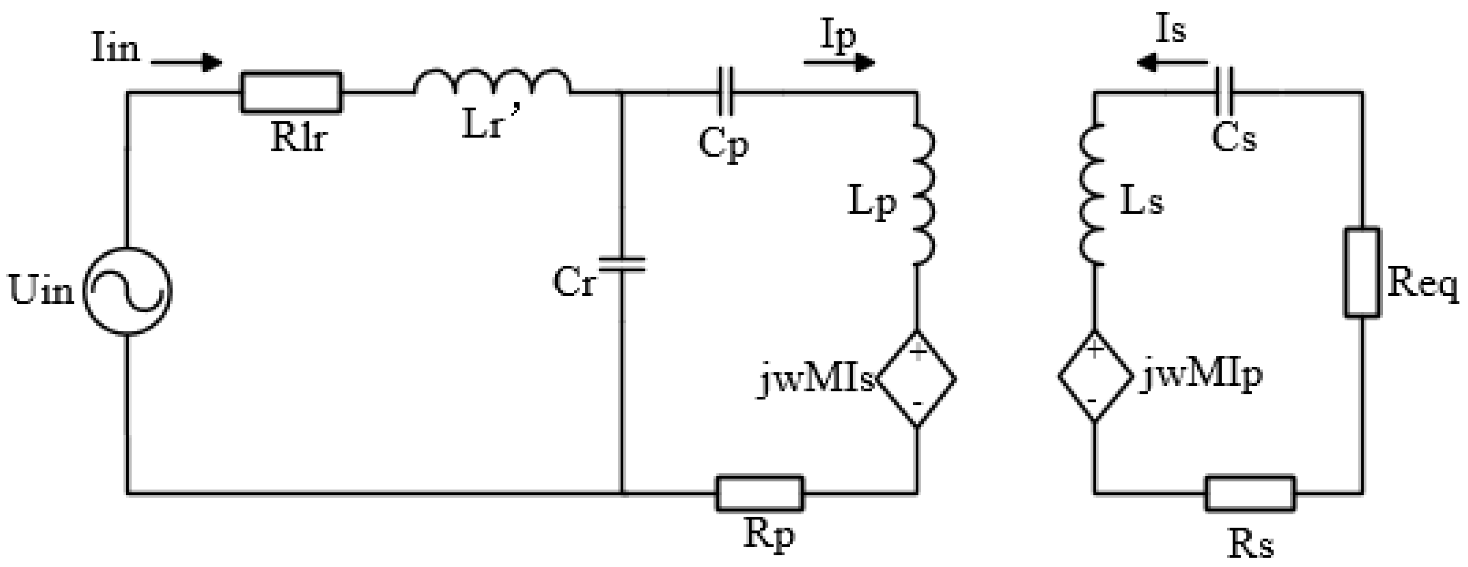
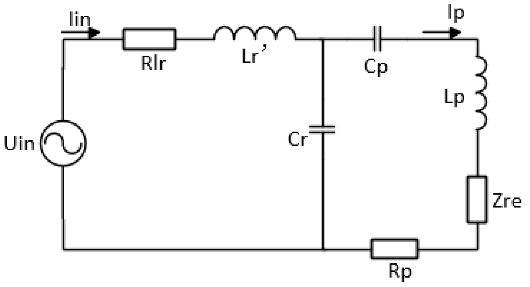
2.1.2. Analysis of the Relationship between Compensation Inductance and System Output Power and Transmission Efficiency

According to fundamental harmonic approximation (FHA), the commonly used LCC compensation topology is analyzed. In order to verify the essential features of the compensation LCC topology, in the alternating current analysis, only the first fundamental sinusoidal equivalents of the square wave output voltage and input voltage are considered [27]. The contribution of all high-order harmonics is ignored, and the power delivery is supposed to only be through the fundamental component. The power losses of the components are neglected to simplify the analysis. Figure 2 shows the principle of the compensation topology, where Rlr is the self-resistance of Lr, and Rp and Rs represent the self-resistance of Lp and Ls, respectively. Req denotes the equivalent load.
In the system, the significant coupling mutual inductances are considered, which are defined as:
M = k L p L s
where M represents the mutual inductance between the main coil and the receiver coil and k represents the coupling coefficient.
According to Figure 2, the reflection impedance Zre, reflected from the receiving coil to the transmitting coil can be expressed as,
Z r e = ω 2 M 2 R e q + R s
Therefore, Figure 2 can be equivalent to Figure 3 below.
According to Figure 3, using the Kirchhoff Voltage Law (KVL), the system equations are derived as,
[ U i n 0 ] = [ R L r + j ω L r + 1 j ω C r 1 j ω C r 1 j ω C r R p + j ω L p + 1 j ω C r + 1 j ω C p + Z r e ] [ I i n I p ]
To reduce the power converter volt-ampere rating, capacitors at the primary side are typically tuned to make the system resonate at the operating frequency. The resonant relationship is expressed as:
j ω L p + 1 j ω C r + 1 j ω C p = 0
j ω L r + 1 j ω C r = 0
As the value of compensation inductance changes with operating time, the relationship between the compensation inductor and capacitor can be denoted as,
j ω L r + 1 j ω C r = j ω Δ L r
where Δ L r represents the difference in the resonant compensation inductance value. By substituting Equations (4) and (6) into (3), the input voltage and the current of the main coil can be calculated as:
I p = I in j ω C r ( R p + Z r e )
U in = [ R L r + 1 ω 2 C r 2 ( R p + Z r e ) ] I in + j ω Δ L r I in
Therefore, the system output power and the transfer efficiency of the system can be expressed as:
P o u t = I p 2 Z r e R e q R e q + R s = | I in | 2 Z r e ω 2 C r 2 ( R p + Z r e ) 2 R e q R e q + R s
P i n = I p 2 ( R p + Z r e ) + I in 2 R L r
η = P o u t P i n = Z r e R L r ω 2 C r 2 ( R p + Z r e ) 2 + R p + Z r e R e q R e q + R s
Equation (8) shows that the changes in compensation inductance will cause the system to detune, which will produce a phase difference between the input voltage and input current. Once the current phase leads the voltage phase, then the reverse recovery time of the parasitic diode of the switches will cause a larger shock to the switches itself, which can damage the switches in a severe case. If the input current is not in phase with the input voltage, and there is some significant phase difference, then there will be a large phase angle. In this scenario, there will be more unused power in the system, resulting in low system output power.
In Equation (9), it can be seen that the output power of the system has a relationship with the total input current Iin, whereas Iin depends on the compensation inductance Δ L r . Hence, it can be deduced that the compensation inductance Lr affects the system output power. Therefore, with the continuous operation of the system for a longer period of time, the heat generated by the coil current will change the ambient temperature, which will alter the temperature of the magnetic core. This change in the temperature will lead to increasing the compensating inductance value of Δ L r , relatively, and the system output power will become smaller. Thus, in order to ensure that the output power is constant, some effective measures need to be taken when designing the compensation inductance.
From Equation (11), it can be seen that the transfer efficiency of the WPT system has nothing to do with the compensation inductance. In other words, no matter how the compensation inductance changes, the system transfer efficiency remains constant given that the other parameters in the topology are unchanged.

2.2. Simulations—Relationship between the Magnetic-Core Compensation Inductance and the Output Power and the Phase Shift Angle

To study the relationship between the output power and the compensation inductance of the magnetic-core inductor, the proposed system is simulated in MATLAB R2015 b. A list of key design parameters is summarized in Table 1.
The circuit sensitivity characteristics are shown in Figure 4. It can be seen that the system has higher output power when the compensation inductance Lr is between 130 μH and 165 μH. The power decreases quickly when the compensation inductance leaves this range in either direction. It also can be seen that the input current of the primary coil is in phase with the input voltage when compensation inductance Lr is 135 μH. If the compensation inductance value changes, the phase shift angle also changes, due to which the switches will not open when the voltage crosses zero.
Obviously, it can be seen that the simulation results are consistent with the theoretical analysis results in Section 2. Therefore, the stability of the compensation inductance is of high importance when designing an appropriate topology for a WPT system [28]. We must take this into account when we design a system for optimal output power, but not assume the compensation inductance to be constant.

3. Solution and Simulations

3.1. Analysis of the Proposed Integrated Compensation Inductor Structure

To make the system more stable and robust, the integration of the compensation coil into the transmitting coil is proposed. Unlike the structure in [29,30], The transmitting coil is a single-coil structure, while the compensation coils are two coils distributed on both sides of the transmitting coil.
The integrated compensation inductor structure proposed in this paper is based on the LCC compensation network shown in Figure 2. An identical compensation coil is added to each side of the transmitting coil. Therefore, in the analysis of the WPT system, it is necessary to consider the mutual inductance between the transmitting coil and the compensation coils, the mutual inductance between the receiving coil and the compensation coils, as well as the mutual inductance between the two compensation coils. The equivalent circuit of the proposed LCC-S compensation topology is shown in Figure 5.

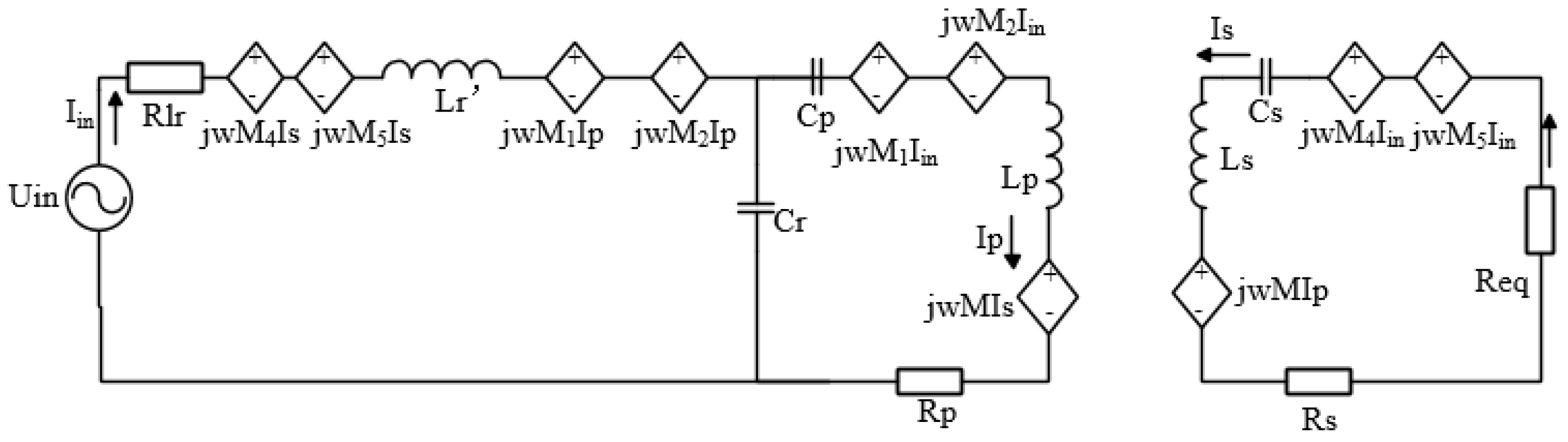
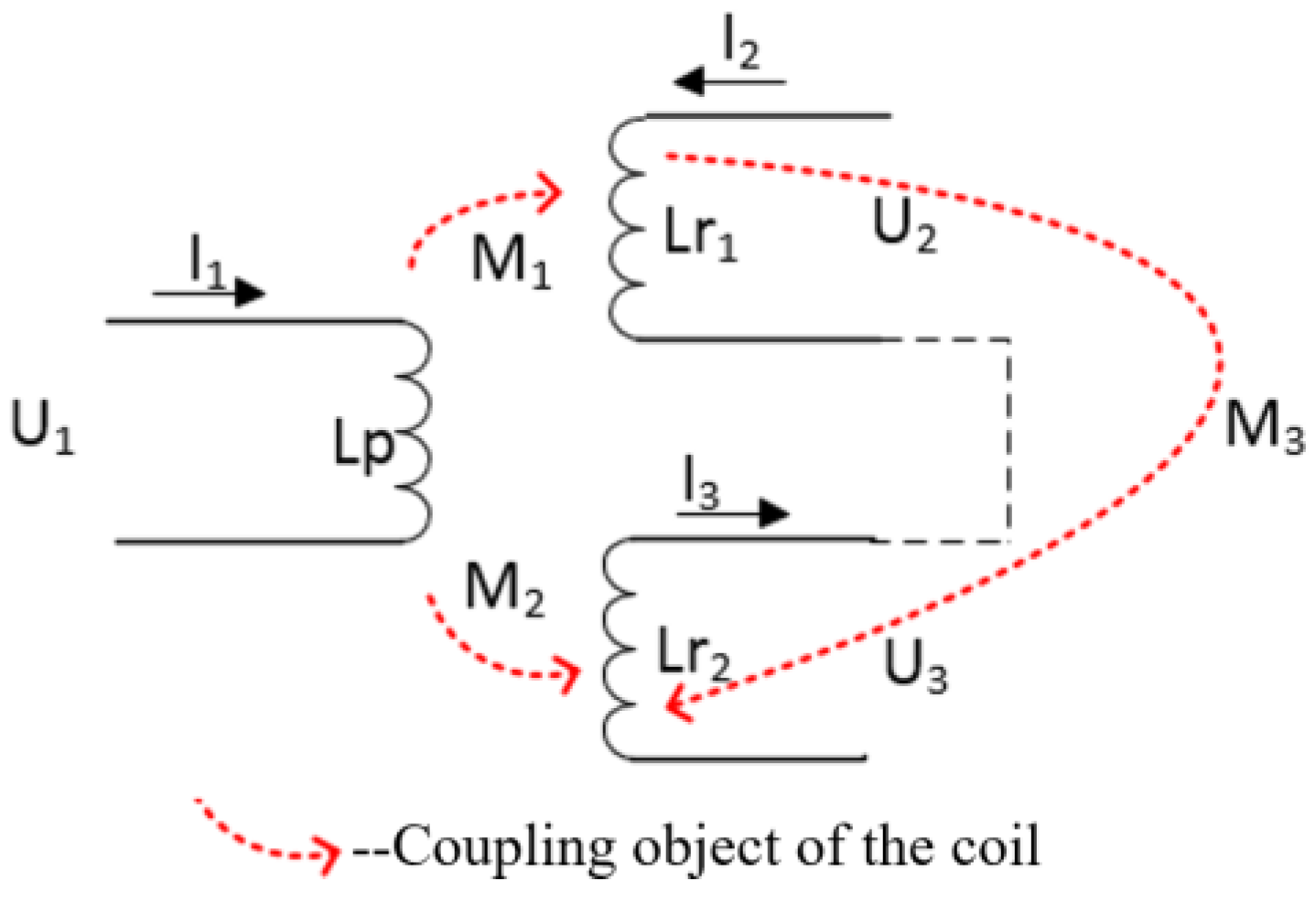
3.1.1. Analysis of Mutual Inductance between the Transmitting Coil and Integrated Compensation Inductor Coils

The equivalent mutual inductances between the transmitting coil and compensation coils of the proposed system are shown in Figure 6, where M1 denotes the mutual inductance between the main coil Lp and the compensation coil Lr1, M2 denotes the mutual inductance between the main coil Lp and the compensation coil Lr2, and M3 denotes the mutual inductance between the compensation coils Lr1 and Lr2.
The Kirchhoff Current Law (KCL) equations for the structure shown in Figure 6 are expressed as:
U 2 = j ω L r 1 · I 2 + j ω M 1 · I 1
U 3 = j ω M 2 · I 1 j ω L r 2 · I 3
The compensation coils are bipolar and symmetric, hence:
I 2 = I 3
M 1 = M 2
L r 1 = L r 2
By substituting (14), (15), and (16) into (12) and (13), we obtain:
U 2 + U 3 = j ω L r 1 I 2 + j ω L r 2 I 2
From the above equations, it can be seen that even though the compensation coils are integrated with the main coils, the mutual inductances M1 and M2 can cancel each other’s effects. So, in this design, the primary-side coils have no effect on the compensation coils whether the receiving coil is offset from the transmitting coil or not. The mutual inductance M3 is zero as well, because the compensation coils are bipolar and symmetric. In this way, the compensation inductors will not be mistuning and the output power can be kept at a constant level when the system is in working condition.

3.1.2. Analysis of Mutual Inductance between the Receiving Coil and Integrated Compensation Inductor Coils

The analysis of the mutual inductance characteristics between the receiving coil and the integrated compensation inductance coil is based on the following three cases:
  • Analysis without misalignment.
  • When the transmitting and the receiving coils are well aligned, and the integrated compensation coils are bipolar and distributed on both sides of the transmitting coil, then the total mutual inductance between the receiving coil and the compensation inductor coils is zero, which is also testified in the following part.
  • Misalignment performance analysis.
As the purpose of this paper is to explore the impact of changes in compensation inductance on output power, etc., and propose solutions, although transfer efficiency is the main point of a WPT system, the effect of misalignment on transfer efficiency will not be discussed in detail in this article. Using horizontal misalignment as an example, a simple analysis is provided.
Because the compensation coils have no effect on the transmitting coil, according to circuit given in Figure 5, using KVL the system equations are derived as:
[ U i n 0 0 ] = [ R L r + j ω L r + 1 j ω C r 1 j ω C r j ω M 4 + j ω M 5 1 j ω C r R p + j ω L p + 1 j ω C r + 1 j ω C p j ω M j ω M 4 + j ω M 5 j ω M R e q + R s ] [ I i n I p I s ]
Theoretically, the mutual inductance between the receiving coil and the compensation coils cannot be ignored when there is a misalignment in the horizontal direction. In this case, M will decrease and the total mutual inductance between the receiving coil and the compensation coils will increase, which is testified in the simulation part. The results have shown that the coupling coefficient between the receiving coil and the compensation inductance coils is already very small compared to the coupling coefficient between the transmitting coil and receiving coil within a 50 mm left–right misalignment. In this scenario, it can also be ignored in actual engineering. Hence, when analyzing parameters such as transfer efficiency in the case of coil misalignment, the analysis method of the proposed integrated structure can be the same as the commonly used separated structure.

3.2. Simulation of the WPT System with Integrated Inductor

In order to validate the outlined analytical results, the proposed integrated compensation coils were simulated using the three-dimensional finite-element analysis tool COMSOL Multiphysics 5.3. The simulation model was shown in Figure 7, and the size of the model is the same as the actual experimental prototype in Section 4. The dimension parameters of the simulated model are listed in Table 2.

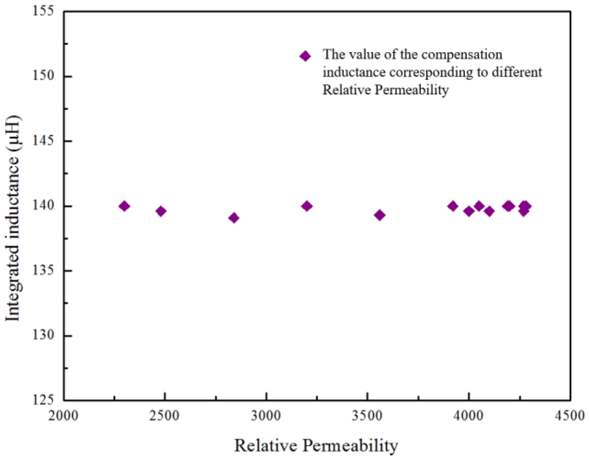
3.2.1. Simulation of the Stability of the Proposed Compensation Inductor

Due to the large magnetic plate used in the compensation coil, it is very tedious to verify its stability by changing the relative permeability of the magnetic sheet through experiments, and the existing equipment is inconvenient to operate. Therefore, in this paper, the stability of the proposed compensation inductor was only verified by simulation. Given that the other conditions remain unchanged, a series of inductance values were simulated by changing the permeability parameter of the integrated inductor material through COMSOL Multiphysics 5.3 software. The results are shown in Figure 8, which substantiates that the inductance of the integrated inductor does not vary with the relative permeability. Therefore, using the proposed structure the system can maintain its resonance state all the time.

3.2.2. Simulation without Misalignment

By providing 6A of current to the proposed compensation inductor coil and simulating the model shown in Figure 7, the self and mutual inductances between the coils are listed in Table 3. Utilizing the steady-state analysis method, a geometrical analysis of the coils was conducted via simulation, and self-inductance and mutual inductance between the compensation coils, the transmitting coils, and the receiving coils were calculated through global evaluation. By providing a 5A current to the transmitting coil and the receiving coil in turn, the self-inductance and mutual inductance are also provided in Table 3.
It can be seen that the mutual inductances M1 and M2, and M4 and M5 have the same absolute value, but they are going in different directions, so the overall mutual inductance between the transmitting coil and compensation inductor coil and the mutual inductance between the receiving coil and compensation inductor coil can be ignored when the transmitting coil and the receiving coil are well aligned.

3.2.3. Misalignment Performance Simulation

Offsetting the receiving coil horizontally by 50 mm and providing 6A of current to the proposed compensation inductor coil, the steady-state analysis method was utilized and a geometry analysis of the coils was conducted via simulation. The self-inductance and mutual inductance between the compensation coils and the receiving coils were calculated through global evaluation and are listed in Table 4.
Through comparative analysis, the mutual inductance between the receiving coil and the compensation inductor coil is much smaller than the mutual inductance between the receiving coil and the transmitting coil, hence it can be ignored.
In general, this section verifies that the proposed compensation inductance is not affected by the transmitting and receiving coils. This is mainly because this winding method has a very large air gap between the compensation coils. As a result, the coil parameters do not change significantly with the permeability, which ensures the stability of the compensation inductor.

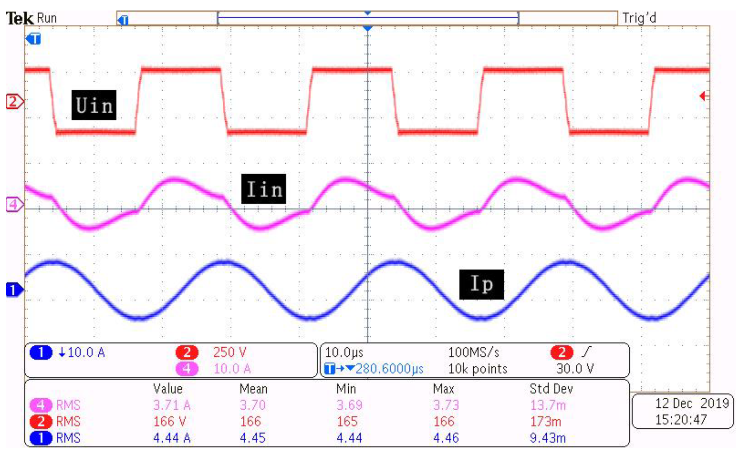
4. Experiment and Results

4.1. Experiment Setup

An LCC-S compensation WPT prototype was built with the compensation parameters listed in Table 1 and the specification size parameters listed in Table 2. Due to the component tolerances, the actual measured parameters in this experiment were slightly different from the design values in Table 1. The switching devices used were Sic C2M0080120 MOSFETs. The coils and inductors were wound by Litz wire, and the shape of the transmitting coil and receiving coil is a square and ring, respectively. The prototype of the coils is shown in Figure 9a,b. In order to achieve the inductance value and minimize the size of the system, the Litz wire used by the transmitting coil and receiving coil were 300 strands and 1200 strands, respectively. Using this coupler, an experimental setup was built as shown in Figure 10. In this setup, the magnetic material PC40 was used to build the magnetic plates. They were placed close to the coils to increase the coupling effect [27]. A constant dc source of 170 V was applied at the primary side, and the secondary side was connected to an electronic dc load to emulate a battery. In this experiment, the resistance of the load was kept constant.
By changing the turns number of the air-core inductor, 6 different resonance inductance values are obtained and applied to the WPT system for a comparative test. The purpose of this experiment is to validate the simulation results and to prove the effect of the change in compensation inductance value on the system output power. The air-core inductors used in the experiment are shown in Figure 9c. Furthermore, in order to illustrate the effectiveness of the integrated inductor, an integrated compensation coil was also applied to the experimental platform in the case of misaligned and well aligned.

4.2. Results and Discussion

When the transmitting coil and receiving coil are directly opposite, the comparison results are shown in Figure 11. From Figure 11a, we can see that the system has higher output power when the compensation inductance Lr is between 130 μH and 165 μH. It decreases quickly when the compensation inductance leaves this range in either direction. Clearly, the experimental results are nearly consistent with the numerical calculations, with an error margin of 3%. Since the calculation was based on the FHA method and only the fundamental harmonic current was considered, the power difference in Figure 11a can be explained by the presence of third-order harmonics [1]. Figure 11b shows the comparison between experimental and simulated results about the phase shift angle between the input current and input voltage. Both the experimental and simulated data point out that there is an angle between the input current and the input voltage when the compensation inductor is smaller or bigger than 135 μH. The smaller the value of the compensation inductor, the larger the phase angle. At this point, the load is capacitive, which can reduce the service life of the MOSFETs. Therefore, it is of great concern to stabilize the compensation inductor. The comparison of the system transfer efficiency between the experimental and simulated system is shown in Figure 11c. It can be seen that the transfer efficiency hardly changes with the inductance value and is always maintained at the maximum point. It can also be seen that compared to the simulation model, the efficiency of the experimental setup is a little less. The mentioned difference in the efficiency is due to the switching losses and conduction losses in the experimental components, which are not considered in the simulation model. Based on the above discussion, it can be deduced that the transfer efficiency of the system has little to do with the resonant inductance.
The same experiment was performed with the proposed integrated inductor instead of the air-core inductor when the receiving coil is directly opposite to the transmitting coil. The system output power result is also shown in Figure 11a. It can be seen that the output power did not change as the experiment progressed for more than one hour, which is consistent with the above simulation analysis. Figure 12 shows that the input current and the input voltage are always in phase no matter how the dc source changes and the current of the primary−side coil remains constant, which can reduce the switching loss effectively. It is indicated that the integrated compensation inductance is very stable and can keep the system working in resonance all the time.
In order to verify the simulation results when the coil is shifted, experiments with an integrated inductor were also performed by shifting the receiving coil to the left and right by 50 mm, respectively. The results were also shown in Figure 11. It can be seen that the phase angle between the input current and the input voltage has nothing to do with the misalignment. When the coil is offset by 50 mm, the coupling coefficient is measured as 0.23 and the transmission efficiency is 91.8%. Compared with the results from when the coil is directly opposite, this change is very small, which can further illustrate the practicability and reliability of the proposed compensation coil structure.
From the above discussion, it is validated that the experimental results generally support the theoretical derivations and numerical simulations presented in Section 2 and in Section 3. In addition, by using this integrated magnetic coupler, the volume of the WPT system can be significantly reduced and in the long term, it is more economical.

5. Conclusions

In this paper, properties of different types of inductors are introduced and the relationship between compensation inductance and output power is theoretically analyzed. According to actual experiment and simulation analysis, this paper points out that the commonly used iron core inductance is susceptible to the environmental temperature, which can easily affect the output power of a WPT system. In order to solve the above problem, an integrated LCC-S compensation topology for wireless power transfer systems was proposed. The additional inductors are integrated with the main coils, where the main coil is unipolar while the compensation coils are bipolar. This structure saves on space needed for additional inductors, unlike a structure that is not integrated. Simulation works are presented to validate the solution and the results showed that the compensation coils are very stable and not affected by ambient temperature, so the system can remain highly efficient from beginning to end. Finally, experiments of a WPT system under various compensation inductors were taken and the results indicated that the mistuning of compensation inductors has a great impact on the output power. In contrast, an experiment of a WPT system with the proposed integrated inductors is taken at the same time, and the integrated compensation inductance has shown good stability and feasibility.

Author Contributions

Conceptualization, B.Z., Y.C. and Y.H.; methodology, Y.H.; software, B.Z., Y.G., X.H., J.T. and S.H.; validation, B.Z., Y.C. and Y.H.; formal analysis, B.Z. and Y.C.; investigation, B.Z.; resources, Y.H.; data curation, B.Z. and S.H.; writing—original draft preparation, B.Z.; writing—review and editing, B.Z., Y.C. and Y.G.; visualization, B.Z.; supervision, Y.H. and Y.C.; project administration, Y.H.; funding acquisition, Y.H. All authors have read and agreed to the published version of the manuscript.

Funding

This research was funded by “Shandong Province Science and Technology Small and Medium Enterprises Improvement Project” (“2022TSGC2075” “2022TSGC2350”).

Institutional Review Board Statement

Not applicable.

Informed Consent Statement

Not applicable.

Data Availability Statement

All data are presented in the article.

Conflicts of Interest

The authors declare no conflicts of interest.

References

  1. Li, S.; Li, W.; Member, S. A Double-Sided LCC Compensation Network and Its Tuning Method for Wireless Power Transfer. IEEE Trans. Veh. Technol. 2015, 64, 2261–2273. [Google Scholar] [CrossRef]
  2. Moon, S.C.; Moon, G.-W. Wireless Power Transfer System with an Asymmetric 4-Coil Resonator for Electric Vehicle Battery Chargers. IEEE Trans. Power Electron. 2016, 31, 6844–6854. [Google Scholar] [CrossRef]
  3. Miller, J.M.; Daga, A. Elements of Wireless Power Transfer Essential to High Power Charging of Heavy Duty Vehicles. IEEE Transact. Transp. Elect. 2015, 1, 26–39. [Google Scholar] [CrossRef]
  4. Mi, C.C.; Buja, G.; Choi, S.Y.; Rim, C.T. Modern advances in wireless power transfer systems for roadway powered electric vehicles. IEEE Trans. Ind. Electron. 2016, 63, 6533–6545. [Google Scholar] [CrossRef]
  5. Beh, H.Z.Z.; Neath, M.J.; Boys, J.T.; Covic, G.A. An Alternative IPT Pickup Controller for Materials Handling using a Current Doubler. IEEE Trans. Power Electron. 2018, 33, 10135. [Google Scholar] [CrossRef]
  6. Chen, L.J.; Boys, J.T.; Covic, G.A. Power Management for Multiple-Pickup IPT Systems in Materials Handling Applications. IEEE J. Emerg. Sel. Top. Power Electron. 2015, 3, 163–176. [Google Scholar] [CrossRef]
  7. Boys, J.T.; Covic, G.A.; Green, A.W. Stability and control of inductively coupled power transfer systems. IEEE Proc.-Electr. Power Appl. 2000, 147, 37–43. [Google Scholar] [CrossRef]
  8. Kojima, T.; Tanabe, H.; Imakiire, A.; Fuji, K.; Kozako, M.; Hikita, M.; Imoto, Y.; Honda, K. Characterization of Contactless Power Transfer System and Investigation of Core Shape for AGV Application. In Proceedings of the 2015 IEEE 11th International Conference on Power Electronics and Drive Systems, Sydney, Australia, 9–12 June 2015. [Google Scholar] [CrossRef]
  9. Nicholas, A.K.; Grant, A.C.; John, T.B. A Unity-Power-Factor IPT Pickup for High-Power Applications. IEEE Trans. Ind. Electron. 2010, 57, 744–751. [Google Scholar] [CrossRef]
  10. Covic, G.A.; Boys, J.T. Modern trends in inductive power transfer for transportation applications. IEEE J. Emerg. Sel. Top. Power Electron. 2013, 1, 28–41. [Google Scholar] [CrossRef]
  11. Covic, G.A.; Boys, J.T. Inductive power transfer. Proc. IEEE 2013, 101, 1276–1289. [Google Scholar] [CrossRef]
  12. Shin, J.; Shin, S.; Kim, Y.; Ahn, S.; Lee, S.; Jung, G.; Jeon, S.J.; Cho, D.H. Design and implementation of shaped magnetic-resonance-based wireless power transfer system for roadway-powered moving electric vehicles. IEEE Trans. Ind. Electron. 2014, 61, 1179–1192. [Google Scholar] [CrossRef]
  13. Yusop, Y.; Saat, S.; Nguang, S.K.; Husin, H.; Ghani, Z. Design of Capacitive Power Transfer Using a Class-E Resonant Inverter. J. Power Electron. 2016, 16, 1678–1688. [Google Scholar] [CrossRef]
  14. Geng, Y.; Li, B.; Yang, Z.; Lin, F.; Sun, H. A High Efficiency Charging Strategy for a Supercapacitor Using a Wireless Power Transfer System Based on Inductor/Capacitor/Capacitor (LCC) Compensation Topology. Energies 2017, 10, 135. [Google Scholar] [CrossRef]
  15. Ann, S.; Lee, W.-Y.; Choe, G.-Y.; Lee, B.K. Integrated Control Strategy for Inductive Power Transfer Systems with Primary-Side LCC Network for Load-Average Efficiency Improvement. Energies 2019, 12, 312. [Google Scholar] [CrossRef]
  16. Zahid, Z.U.; Dalala, Z.M.; Zheng, C.; Chen, R.; Faraci, W.E.; Lai, J.-S.J.; Lisi, G.; Anderson, D. Modeling and Control of Series–Series Compensated Inductive Power Transfer System. IEEE J. Emerg. Sel. Top. Power Electron. 2015, 3, 111–123. [Google Scholar] [CrossRef]
  17. Jia, H.; Chen, Q.; Wong, S.C.; Chi, K.T.; Ruan, X. Analysis and Control of Series/Series-Parallel Compensated Resonant Converter for Contactless Power Transfer. IEEE J. Emerg. Sel. Top. Power Electron. 2015, 3, 124–136. [Google Scholar] [CrossRef]
  18. Sohn, Y.H.; Choi, B.H.; Lee, E.S.; Lim, G.C.; Cho, G.-H.; Rim, C.T. General Unified Analyses of Two-Capacitor Inductive Power Transfer Systems: Equivalence of Current-Source SS and SP Compensations. IEEE Trans. Power Electron. 2015, 30, 6030–6045. [Google Scholar] [CrossRef]
  19. Zhang, W.; Wong, S.-C.; Tse, C.K.; Chen, Q. Analysis and Comparison of Secondary Series- and Parallel-Compensated Inductive Power Transfer Systems Operating for Optimal Efficiency and Load-Independent Voltage-Transfer Ratio. IEEE Trans. Power Electron. 2014, 29, 2979–2990. [Google Scholar] [CrossRef]
  20. Liu, Y.; Liu, C.; Wang, W.; Liu, S.; Chen, Y. A Novel Wired/Wireless Hybrid Multiport Energy Router for Dynamic EV Energy Internet with Grid-Tied and Islanded Operations. IEEE Trans. Ind. Electron. 2024, 71, 3559–3571. [Google Scholar] [CrossRef]
  21. Feng, H.; Cai, T.; Duan, S.; Zhao, J.; Zhang, X.; Chen, C. An LCC Compensated Resonant Converter Optimized for Robust Reaction to Large Coupling Variation in Dynamic Wireless Power Transfer. IEEE Trans. Ind. Electron. 2016, 63, 6591–6601. [Google Scholar] [CrossRef]
  22. Liu, C.; Ge, S.K.; Guo, Y.; Li, H.; Cai, G.W. Double-LCL resonant compensation network for electric vehicles wireless power transfer: Experimental study and analysis. IET Power Electron. 2016, 9, 2262–2270. [Google Scholar] [CrossRef]
  23. Fei, L.; Hua, Z.; Hofmann, H.; Mi, C. A High Efficiency 3.3 kW Loosely-Coupled Wireless Power Transfer System without Magnetic Material. In Proceedings of the 2015 IEEE Energy Conversion Congress and Exposition, Montreal, QC, Canada, 20–24 September 2015. [Google Scholar] [CrossRef]
  24. Wei, Z.; Mi, C.C. Compensation Topologies of High-Power Wireless Power Transfer Systems. IEEE Trans. Veh. Technol. 2016, 65, 4768–4778. [Google Scholar] [CrossRef]
  25. Kalinikos, B.A.; Ustinov, A.B. Chapter Eight—Ferrites for RF Passive Devices. Solid State Phys. 2013, 64, 237–329. [Google Scholar]
  26. Mn-Zn Ferrite, Material Characteristics. Available online: https://product.tdk.com/info/en/catalog/datasheets/ferrite_mn-zn_material_characteristics_en.pdf (accessed on 1 May 2022).
  27. Lu, F.; Zhang, H.; Hofmann, H.; Su, W.; Mi, C.C. A Dual-Coupled LCC-Compensated IPT System with a Compact Magnetic Coupler. IEEE Trans. Power Electron. 2018, 33, 6391–6402. [Google Scholar] [CrossRef]
  28. Li, W.; Mi, C.C.; Li, S.; Deng, J.; Han, Z. Integrated LCC Compensation Topology for Wireless Charger in Electric and Plug-in Electric Vehicles. IEEE Trans. Ind. Electron. 2015, 62, 4215–4224. [Google Scholar] [CrossRef]
  29. Budhia, M.; Boys, J.T.; Covic, G.A. Development of a Single-Sided Flux Magnetic Coupler for Electric Vehicle IPT Charging Systems. IEEE Trans. Ind. Electron. 2013, 60, 318–328. [Google Scholar] [CrossRef]
  30. Zhou, S.; Mi, C. Multi-Paralleled LCC Reactive Power Compensation Networks and Its Tuning Method for Electric Vehicle Dynamic Wireless Charging. IEEE Trans. Ind. Electron. 2016, 63, 6546–6556. [Google Scholar] [CrossRef]
Figure 1. Circuit topology of a conventional inductor/capacitor/capacitor (LCC)-compensated single-coupled wireless power transfer (WPT) system.
Wevj 15 00045 g001
Figure 2. LCC−S compensation equivalent circuit.
Wevj 15 00045 g002
Figure 3. Equivalent transformation of LCC-S compensation.
Wevj 15 00045 g003
Figure 4. Sensitivity analyses with different compensation inductances from different perspectives: primary coil current and phase shift angle between input current and input voltage.
Wevj 15 00045 g004
Figure 5. Equivalent circuit of the proposed LCC−S compensation topology.
Wevj 15 00045 g005
Figure 6. Equivalent mutual inductances between main coils and compensation coils.
Wevj 15 00045 g006
Figure 7. Structural details of the proposed integrated coupler: (a) overview of coil structures; (b) front view of the model.
Wevj 15 00045 g007
Figure 8. Relationship between the relative permeability and the proposed compensation inductance.
Wevj 15 00045 g008
Figure 9. Prototype of an integrated magnetic coupler: (a) primary-side coil integrated with compensation inductors; (b) receiving coil; (c) prototype of the air-core inductor.
Wevj 15 00045 g009
Figure 10. Experimental setup of an LCC-S compensation WPT system.
Wevj 15 00045 g010
Figure 11. Comparison of results: (a) comparison of experimental and calculated output power; (b) comparison of phase shift angle between input current and input voltage; (c) comparison of the system transfer efficiency between the experiment and simulation.
Wevj 15 00045 g011
Figure 12. Experimental waveforms obtained by using an integrated magnetic coupler.
Wevj 15 00045 g012
Table 1. Key design parameters and their specifications.
SymbolNoteValue
fResonant frequency39 KHz
dDistance between transmitting and receiving coils70 mm
Lp, LsPrimary and secondary inductors403 µH, 30 µH
LrCompensation inductance0.1~320 µH
CrCompensation capacitor0.117 µF
Cp, CsPrimary and secondary series capacitors0.065 µF, 0.52 µF
kCoupling coefficient0.23
Rp, RsPrimary and secondary coil self-resistance0.2 Ω, 0.1 Ω
Rlrcompensation inductor self-resistance0.2 Ω
ReqEquivalent load1.4 Ω
UinInput voltage170 V
Table 2. Specific size parameters of simulation model and experiment system.
SymbolNoteValue
lf1, bf1Length and width of magnetic plate (transmitting end)515 mm, 340 mm
bf2Length and width of magnetic plate (receiving end)298 mm
Lc1Side length of transmitting coil296 mm
dc1Hole pitch of transmitting coil186 mm
Lc2Diameter of receiving coil183 mm
dc2Hole pitch of receiving coil94 mm
Lc3, bc3Length and width of compensation coil295 mm, 85 mm
dDistance between transmitting coil and receiving coil150 mm
d1Hole pitch of compensation coil20 mm
d2Distance between compensation coils and transmitting coil23 mm
d3, d4Distance between magnetic plate and coils3 mm
hc1, hc2Thickness of coils4 mm
hf1, hf2Thickness of magnetic plate6 mm
NpTransmitting coil turns23
NsReceiving coil turns10
N1Number of turns of left compensation coil13
N2Number of turns of right compensation coil13
Table 3. Results of different mutual inductances without misalignment.
SymbolNoteValue (μH)
LpSelf-inductance of transmitting coil404.09
M1Mutual inductance between Lp and Lr113.64
M2Mutual inductance between Lp and Lr2−13.64
LsSelf-inductance of receiving coil31.60
M4Mutual inductance between Ls and Lr11.20
M5Mutual inductance between Ls and Lr2−1.20
MMutual inductance between Lp and Ls32.37
Table 4. Results of different mutual inductances with misalignment.
SymbolNoteValue (μH)
LpSelf-inductance of transmitting coil410.21
M1Mutual inductance between Lp and Lr113.64
M2Mutual inductance between Lp and Lr2−13.64
LsSelf-inductance of receiving coil31.60
M4Mutual inductance between Ls and Lr1 (horizontal shift 50 mm)−1.68
M5Mutual inductance between Ls and Lr2 (horizontal shift 50 mm)0.77
MMutual inductance between Lp and Ls28.96
Disclaimer/Publisher’s Note: The statements, opinions and data contained in all publications are solely those of the individual author(s) and contributor(s) and not of MDPI and/or the editor(s). MDPI and/or the editor(s) disclaim responsibility for any injury to people or property resulting from any ideas, methods, instructions or products referred to in the content.

