Article

Topology Optimization Design and Dynamic Performance Analysis of Inerter-Spring-Damper Suspension Based on Power-Driven-Damper Control Strategy

1
Automotive Engineering Research Institute, Jiangsu University, Zhenjiang 212013, China
2
Chinese Scholartree Ridge Laboratory, China North Vehicle Research Institute, Beijing 100072, China
3
Weichai (Yangzhou) Yaxing New Energy Commercial Vehicle Co., Ltd., Yangzhou 225000, China
4
School of Automotive and Traffic Engineering, Jiangsu University, Zhenjiang 212013, China
*
Author to whom correspondence should be addressed.
World Electr. Veh. J. 2024, 15(1), 8; https://doi.org/10.3390/wevj15010008
Submission received: 9 November 2023 / Revised: 19 December 2023 / Accepted: 20 December 2023 / Published: 26 December 2023
(This article belongs to the Special Issue Advanced Vehicle System Dynamics and Control)

Abstract

:
In this paper, the problem of broadband vibration suppression of power-driven-damper vehicle “inerter-spring-damper” (ISD) suspension is studied. The suspension can effectively inherit the low-frequency vibration suppression effect of ISD suspension and the high-frequency vibration suppression effect of the power-driven-damper control strategy. Based on the structural method, this paper proposes four suspensions with different structures. The optimal structure and parameters are obtained by using pigeon-inspired optimization. The results show that, based on the optimal structure, the Root-Mean-Square (RMS) of body acceleration and the RMS of suspension working space are reduced by 23.1% and 6.6%, respectively, compared to the traditional passive suspension. The influence of the damping coefficient on the dynamic performance of the power-driven-damper vehicle ISD suspension is further studied. The vibration suppression characteristics of the proposed suspension are simulated and analyzed in both the time domain and frequency domain. It is shown that the power-driven-damper vehicle ISD suspension can effectively reduce vibrations across a wide frequency range and significantly improve body acceleration and suspension working space, thereby enhancing the ride comfort.

1. Introduction

The suspension system is a crucial component of the chassis structure. It is responsible for supporting the vehicle’s weight and for absorbing and reducing the impact of vibrations caused by uneven road surfaces. The comprehensive performance of the suspension directly affects its ride comfort, handling stability, and driving safety. Therefore, the improvement of suspension performance is crucial [1,2,3]. The traditional passive suspension has been widely used due to its low cost and simple structure. However, its single structure limits the potential for improving the vibration isolation performance of the suspension system [4,5,6]. In 2002, Professor Smith proposed the concept of inerter, and the performance of passive suspension has since been further developed. The inerter is a mechanical component with two-end motion characteristics; its purpose is to compensate for the lack of mass impedance. It has been utilized in various fields, such as building vibration isolation and aircraft landing gear. In recent years, the structure of passive suspension has become more diverse with the introduction of inerter. We refer to the suspension with the core structure of “inerter-spring-damper” as ISD suspension. The introduction of the inerter has greatly expanded the topology of suspension, and the research on ISD suspension structure has emerged endlessly [7,8,9]. Chen designed a two-stage tandem ISD suspension structure based on the electromechanical similarity principle [10]. Jiang constructed 12 suspension systems with inerter and utilized multi-objective optimization methods to optimize the suspension parameters. The simulation results show that, compared with traditional suspension, there are eight types of ISD suspension structures that exhibit better performance. Among them, four types of ISD suspension structures have significant vibration reduction effects [11]. Xie established eight types of ISD seat suspensions and analyzed the model’s dynamic response across various frequency bands. The results indicate that seat suspension with inerter provide significant advantages in vibration isolation compared to traditional seats suspension. They have a notable effect on low-frequency vibration isolation, but their effectiveness is limited in the high-frequency range [12]. Nie proposed a new hybrid ISD suspension. Simulation results indicated that the structure could decrease the vertical weighted acceleration at the seat by 26% and significantly improve the ride comfort [13]. Papageoriou transformed the network structure design of suspension systems into the optimization solution for the positive real impedance transfer function and designed the suspension structure through the passive network synthesis theory [14]. Based on this, Jiang studied the structural realization of high-order impedance [15]. Zhang proposed a new a new method for suspension structure design called structural impedance method. This method can simultaneously consider a complete set of absorber layouts and limit the complexity, topology, and element values of the candidate layouts [16]. Vehicle ISD suspension has significantly improved its topological characteristics compared to traditional suspensions, and it can effectively suppress the body vibration in the low-frequency range, but it has poor vibration suppression effect in the high-frequency range and cannot effectively suppress vibration across a wide frequency range.
While the use of inerters can passively improve the dynamic properties of vehicles, semi-active suspension systems were developed to provide a more balanced compromise between cost and performance. In a semi-active suspension system, the damping force can be adjusted based on operating conditions to improve suspension performance [17,18,19]. Karnopp and Crosby first proposed the concept of semi-active suspension. Under the concept of semi-active suspension, a variety of excellent control strategies for semi-active suspension have emerged [20]. Karnopp proposed a skyhook (SH) control strategy to suppress body vibration by installing an adjustable damper on the sprung mass. This damper produces a damping force that opposes the velocity of the sprung mass [21]. Zhu applied the acceleration-driven-damper (ADD) control strategy to double crossarm suspension, and the research shows that the ADD control strategy can effectively suppress the body vibration [22]. Lin proposed an improved ADD control strategy; the research shows the improved ADD control strategy maintains the optimization effect of the ADD control strategy on sprung mass acceleration and prevents the deterioration of dynamic tire load [23]. Wang analyzed the SH control strategy and the liner-quadratic-regulator (LQR) control strategy, respectively, and he proposed SH-LQR semi-active control to improve ride comfort. According to the simulation results of the semi-vehicle model, the suspension utilizing SH-LQR control improves the body acceleration and pitch angle acceleration by 28.3% and 26.3%, respectively, compared to the passive suspension. Furthermore, the frequency domain analysis shows that the SH-LQR control strategy yields superior control effectiveness in both high and low frequency bands [24]. Savaresi proposed the SH-ADD control strategy, which combines SH control strategy and ADD control strategy, and the research shows that the control strategy an effectively improve the body acceleration in both high and low frequency range [25]. In order to achieve vibration suppression in both the high frequency and low frequency range, the current approach primarily relies on the method of hybrid control strategy design. However, the process of switching between these control strategies can lead to system instability and jitter.
The power-driven-damper control strategy is a semi-active control strategy designed from the perspective of system power requirements. Compared with the ADD control, the power-driven-damper control can effectively improve body vibration in the high-frequency range without causing body shake [26]. Therefore, this paper combines the power-driven-damper control strategy, which can suppress the vibration in the high-frequency range, with the vehicle ISD suspension, which can suppress the vibration in the low-frequency range. The research focuses on the quarter suspension model and analyzes the impact of the power-driven-damper vehicle ISD suspension on the vertical motion of the vehicle.

2. Model Building and Power-Driven-Damper Control Strategy Design

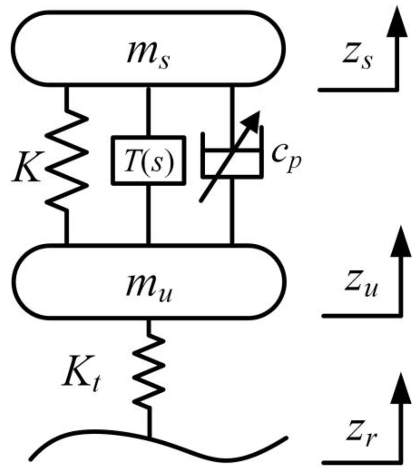
2.1. Quarter Suspension Model

In this paper, a quarter suspension model based on the power-driven-damper control strategy is taken as the research object, as shown in Figure 1.
In the figure, K is the auxiliary spring, cp is the semiactive damper, ms is the sprung mass, mu is the unsprung mass, zs is the vertical displacement of the sprung mass, zu is the vertical displacement of the unsprung mass, zr is the random road input, Kt is the equivalent spring of the tire. T(s) is an intermediate structure consisting of the inerter and springs. The dynamic motion equations of the suspensions are as follows:
m s z ¨ s + K ( z s z u ) + c p ( z ˙ s z ˙ u ) + T ( s ) ( z ˙ s z ˙ u ) = 0 m u z ¨ u + K t ( z u z r ) K ( z s z u ) c p ( z ˙ s z ˙ u ) T ( s ) ( z ˙ s z ˙ u ) = 0

2.2. Power-Driven-Damper Control Strategy Design

Port-controlled Hamiltonian system [27] is a mathematical framework that focuses on capturing the interaction between energy and power in a system’s topology and characterizing the stored energy through Hamiltonian equation. The framework can be used to construct a variety of nonlinear models, such as robotic systems and electromechanical systems. At present, the research of the port-controlled Hamiltonian system focuses on obtaining a closed-loop port-controlled Hamiltonian system. This involves manipulating the power port to derive the corresponding Hamiltonian equation, power interaction equation, and damping parameters. For a generalized port-controlled Hamiltonian system, the dynamic behavior of the system can be described by Equation (2):
x ˙ = [ J ( x ) R ( x ) ] H x ( x ) + g ( x ) u y = g T ( x ) H x ( x ) J ( x ) = J T ( x ) R ( x ) = R T ( x ) 0
where x is the state variable, y is the output variable, and u is the port power variable. J(x) is the power interconnection matrix of the subsystem; R(x) is the damping dissipation matrix. The damping dissipation matrix reflects the damping dissipation energy relationship on the system port H(x) is the Hamiltonian energy function of the system, which stores the energy in the system; g(x) is a function that is associated with the state variable. yTu represents the system power, which can be expressed by Equation (3):
y T u = d H d t + H T x R H x d H d t
Part of the power input to the system is stored as energy, which is quantized by the Hamiltonian energy function H(x). The other part is damped, dissipated, and quantized by the damping dissipation matrix R(x). However, the direct effects of input variables on the dissipative matrix R(x) and the interconnection matrix J(x) have not been taken into account. In order to more accurately describe the electromechanical system using the port-controlled Hamiltonian system framework, we introduce the interconnection matrix J(x,v) and the dissipation matrix R(x,v). These matrices are related to both the input variables and state variables. And Equations (2) and (3) have been modified to derive Equations (4) and (5) as follows:
x ˙ = [ J 1 ( x , v ) R 1 ( x , v ) ] H x ( x ) + g ( x , v ) u y = g T ( x , v ) H x ( x ) [ J 2 ( x , v ) R 2 ( x , v ) ] u J i ( x , v ) = J T i ( x , v )         i = 1 , 2 R i ( x , v ) = R T i ( x , v ) i = 1 , 2
y T u = d H d t H T x R 1 ( x , v ) H x + u T R 2 ( x , v ) u
where v, as the input variable, represents controllable damping, Ji(x,v) represents the power interconnection matrix, and Ri(x,v) represents the power dissipation matrix. The total input power yTu consists of two parts: the first part is the stored power, and the second part is the dissipated power. The dissipated power is denoted as d(v,x) in this paper, and it can be expressed by Equation (6). The corresponding power balance equation can be expressed as Equation (7).
d ( v , x ) = H T x R 1 ( x , v ) H x + u T R 2 ( x , v ) u
H ˙ = y T u d ( v , x )
From the perspective of system power demand, the design of semi-active control strategy based on power-driven-damper can be transformed into a problem of solving an input variable that satisfies the power demand of a port-controlled Hamiltonian system. This can be expressed by the following control methods:
v : arg max ( H ˙ + d ) if arg max ( H ˙ + d ) < W d arg min ( H ˙ + d ) if arg max ( H ˙ + d ) W d W d = H ˙ + d ( v , x ) otherwise
Taking Figure 1 as an example, in the suspension system, the spring and the inerter are energy storage components, while controllable damping is the only energy dissipation component.
Therefore, the stored power is:
H ˙ = K ( z s z u ) ( z ˙ s z ˙ u ) + T ( s ) ( z ˙ s z ˙ u ) 2
The dissipated power is:
d ( c p , x ) = c p ( z ˙ s z ˙ u ) 2
The total suspension system power is:
W d = H ˙ + d ( c p , x ) = K ( z s z u ) ( z ˙ s z ˙ u ) + c p ( z ˙ s z ˙ u ) 2 + T ( s ) ( z ˙ s z ˙ u ) 2
The power-driven-damper control strategy is designed from an energy perspective. The closer the total power is to zero, the stronger its isolation of power. Therefore, the design rules for the control strategy in this paper are as follows: When the net input power in suspension is less than zero, cp is set to its maximum value. When the net input power in suspension is greater than or equal to zero, cp takes the minimum value; When the net input power of suspension is zero, but the relative displacement of suspension is not zero, (indicating that the relative speed is zero, but the relative displacement is not), cp is taken as the average value between maximum and minimum values. This process is considered the transition stage. In the last mode, the cp value ensures zero net input power. The power-driven-damper control strategy avoids the switching conditions associated with body acceleration and can effectively suppress shaking. The conditions that must be met for the controllable damping coefficient cp are as follows:
c p = c max , i f   K ( z s z u ) ( z ˙ s z ˙ u ) + c max ( z ˙ s z ˙ u ) 2 + T ( s ) ( z ˙ s z ˙ u ) 2 < 0 c min , i f   K ( z s z u ) ( z ˙ s z ˙ u ) + c min ( z ˙ s z ˙ u ) 2 + T ( s ) ( z ˙ s z ˙ u ) 2 0 c max + c min 2 , i f   ( z ˙ s z ˙ u ) = 0 & ( z s z u ) 0 K ( z s z u ) T ( s ) ( z ˙ s z ˙ u ) ( z ˙ s z ˙ u ) , else

3. Topological Design and Dynamic Performance Optimization of Suspension Structure

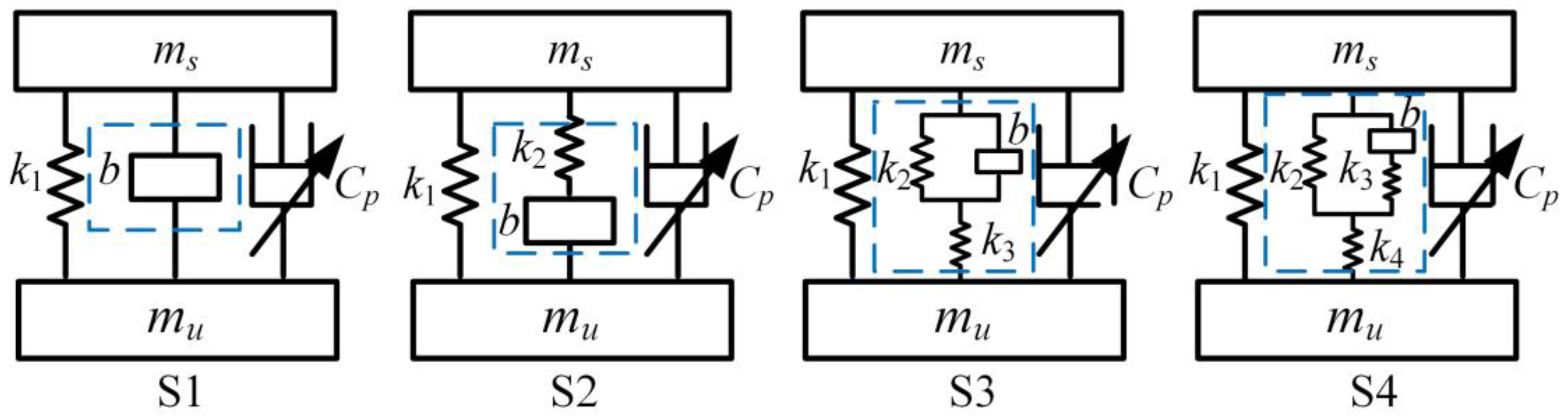
3.1. Suspension Structure Topology Design

In this paper, the number of inerters is limited to 1. By connecting the inerter in series and parallel with different numbers of springs, a total of four types of power-driven-damper vehicle ISD suspensions with different structures are obtained, namely S1, S2, S3, and S4, as shown in Figure 2.
The transfer function of the velocity impedance for these four intermediate suspension structures is:
T S 1 s = b s T S 2 s = k 2 b s b s 2 + k 2 T S 3 s = k 3 b s 2 + k 2 k 3 b s 3 + ( k 2 + k 3 ) s T S 4 s = b k 4 ( k 2 + k 3 ) s 3 + k 2 k 3 k 4 b ( k 2 + k 3 + k 4 ) s 3 + k 3 ( k 2 + k 4 ) s

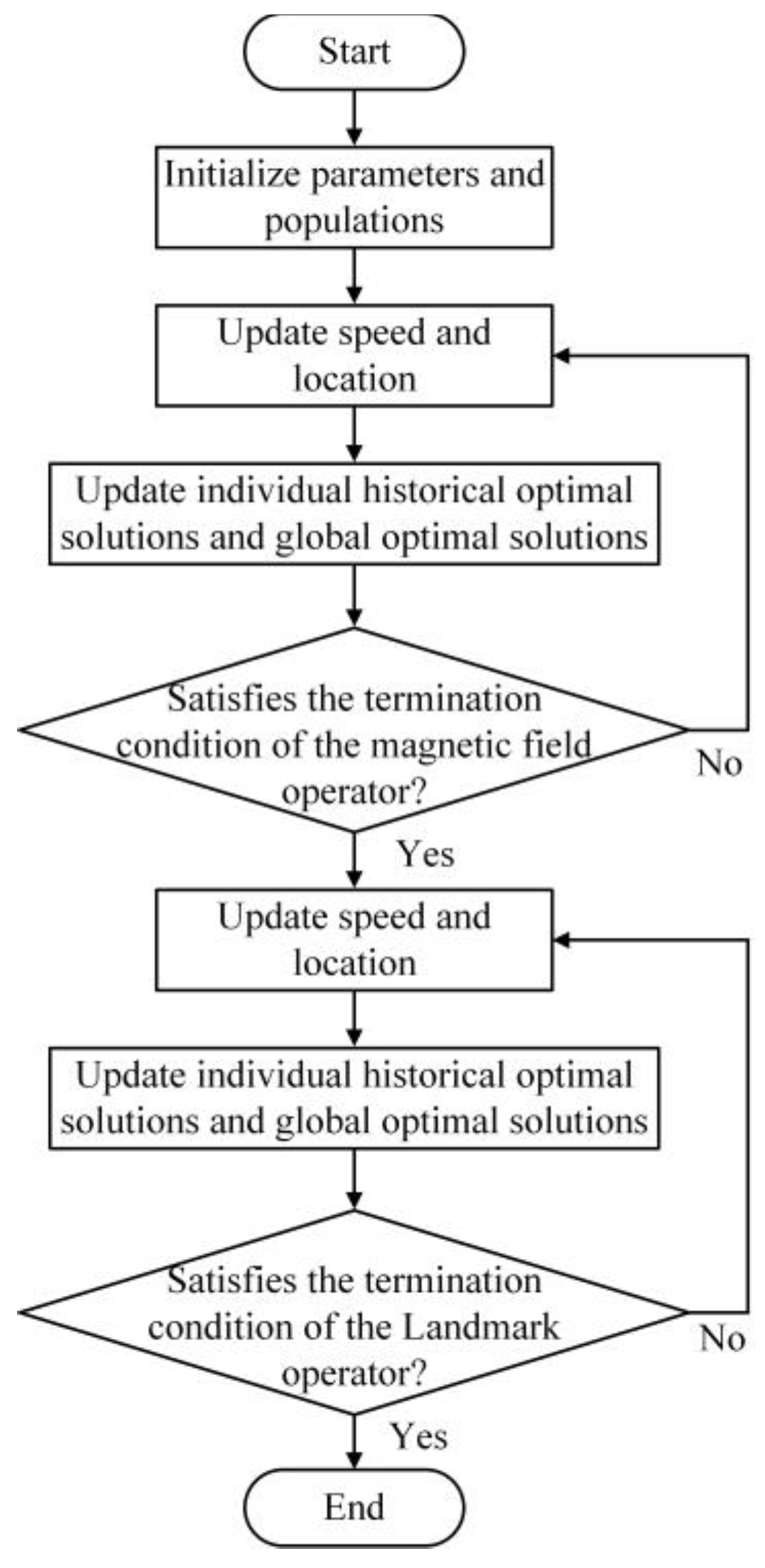
3.2. Dynamic Performance Optimization

In the suspension optimization process, assuming that the vehicle is driving at a speed of u = 20 m/s on a Class C road, the input displacement of road roughness can be expressed as follows:
z ˙ r ( t ) = 0.111 [ u z r ( t ) + 40 G q ( n 0 ) u w ( t ) ]
where zr(t) is the vertical input displacement caused by the road roughness of the model; Gq(n0) is the road roughness coefficient, with a value of 2.56 × 10⁻⁴ m; w(t) denotes integral white noise.
(1) Pigeon-inspired optimization
Optimization algorithms include single-objective optimization algorithms and multi-objective optimization algorithms [28]. The objective of this paper is to optimize body acceleration. Therefore, a single-objective optimization algorithm, pigeon-inspired optimization (PIO), is adopted.
Pigeon-inspired optimization (PIO) [29] is an intelligent optimization algorithm inspired by the homing behavior of pigeons. It has the advantages of global optimality and fast convergence. The PIO optimization algorithm simulates the homing behavior of pigeons based on magnetic field direction and landmarks to achieve the optimization process. The PIO algorithm can be roughly divided into two stages: the magnetic field operator and the landmark operator. During the stage of magnetic field operation, pigeons used the solar height and geomagnetic field as navigation tools in their homing behavior when they were far away from their destination. During the landmark operator stage, the landmark is used as a homing navigation tool, because the ground objects can be observed when the pigeons are close to the destination. The flow chart of the optimization process is shown in Figure 3.
In the D-dimensional search space, the initial pigeon population is Np, and the position Xi(k) and velocity Vi(k) of the i-th pigeon in k iterations can be expressed as:
X i ( k ) = [ x i 1 , x i 2 , x i D ]
V i ( k ) = [ v i 1 , v i 2 , v i D ]
In the magnetic field operator stage, the positions Xi(k+1) and velocities Vi(k+1) of all pigeons at the next iteration (k + 1) can be updated using the following equation:
V i ( k + 1 ) = V i ( k ) e R k + r a n d ( X g X i ( k ) )
X i ( k + 1 ) = X i ( k ) + V i ( k + 1 )
In Equation (17), R represents the magnetic field factor, rand is a uniformly distributed random number in the range [0,1], and Xg represents the global optimal solution of the current iteration. All pigeons adjust their flight positions according to magnetic field factors, and their positions are assessed using a specific objective function. Assuming that the maximum number of iterations of the magnetic field operator stage is nc1, if the current iteration t exceeds nc1, the magnetic field operator stage is terminated and the landmark operator stage is entered.
During the landmark operator phase, all pigeons are sorted according to their fitness values. In each iteration, the number of pigeons is updated using Equation (19). Only half of the pigeons are taken into account when calculating the desired position of the central pigeon, while the remaining pigeons adjust their destination by following the desired target position. The position of the ideal destination is calculated using Equation (20), while all other pigeons are updated using Equation (21).
N p ( k + 1 ) = N p ( k ) 2
In Equation (19), Np(k) represents the number of pigeons at the current iteration k.
X c ( k + 1 ) = X i ( k + 1 ) F i t n e s s ( X i ( k + 1 ) ) N p F i t n e s s ( X i ( k + 1 ) )
X i ( k + 1 ) = X i ( k ) + r a n d ( X c ( k + 1 ) X i ( k ) )
In Formulas (20) and (21), Xc is the desired position of the central pigeon, and Fitness(·) represents the fitness function of individual pigeons. Assuming that the maximum number of iterations of the landmark operator phase is nc2, if the current iteration k exceeds nc2, the landmark operator phase is aborted. The global optimal solution Xg is achieved by updating the optimal position in each iteration.
(2) Optimize objectives and constraints
In this paper, the optimization objectives for the vehicle ISD suspension model include the spring stiffness ki, inertial coefficient b, maximum adjustable damping coefficient cmax and minimum adjustable damping coefficient cmin. With comfort as the guide, the RMS of body acceleration under the road input, as shown in Equation (14), is taken as the optimization objective. The specific expression is shown below:
q = k i   b   c max   c min
min J = J 1
where J1 represents the RMS of body acceleration of power-driven-damper vehicle ISD suspension under random road input; q represents the set of suspension parameters to be optimized.
This paper establishes certain constraints. J1 should be less than Jpass, which represents the RMS of body acceleration in traditional passive suspension. It is relatively straightforward to calculate Jpass, which is equal to 1.607 m/s2. In order to maintain the integrity of suspension working space and dynamic tire load during the optimization process, the following constraints are imposed [30]: Based on the probability integral table of the normal distribution, if the effective value of the suspension working space is less than or equal to 1/3 of the suspension dynamic deflection [fd], the probability of the suspension working space exceeding the limit travel is only 0.3%. For the passenger car studied in this paper, the range of [fd] is 7~9 cm, which is taken as 8 cm in this paper. For the dynamic tire load, when its effective value does not exceed 1/3 of the static load G, the probability of the wheel jumping off the ground does not exceed 0.15%. The static load G studied in this paper is 3650 N. Since the main spring is the primary support of the suspension, the value range is set at [15,000, 25,000] N·m−1.
In summary, the optimization constraints are as follows:
s . t . J 1 J p a s s J 2 f d 3 J 3 G 3 c max , c min [ 0 ,   10 , 000 ] k 1 [ 10 , 000 ,   25 , 000 ] , k 2 , k 3 , k 4 [ 0 ,   10 , 000 ] b 2 [ 0 ,   4000 ]
The parameters of the passenger car in this paper are shown in Table 1, and the final optimization results are shown in Table 2 [31]. The suspension S0 represents the traditional passive suspension.
As shown in Table 2, the body acceleration is improved after optimizing all structures, and the improvement is more significant as the structure becomes more complex. It is worth noting that the suspension working space is also improved, while the dynamic tire load deteriorates to some extent. This is because optimizing body acceleration may lead to some extent of deterioration in other dynamic performance indicators. When the optimization process concludes, the dynamic tire load reaches the constraint boundary, but its value remains within a reasonable range.
The suspension S4 has achieved the most significant improvement in body acceleration, with a 23.1% decrease in body acceleration. The suspension working space of suspension S1 has been significantly improved, with a 17.8% decrease in suspension working space. However, the body acceleration of suspension S1 has only decreased by 11.4%. The body acceleration of suspension S2 and suspension S3 decreased by 13.7% and 20.0%, respectively. However, the improvement is not as significant as that of suspension S4. This paper is comfort-oriented, the body acceleration can directly reflect whether the ride comfort is excellent. Compared to other suspensions, the suspension S4 has the best effect on improving body acceleration. Therefore, the suspension S4 was chosen as the research object to analyze its dynamic characteristics.

4. Dynamic Performance Analysis

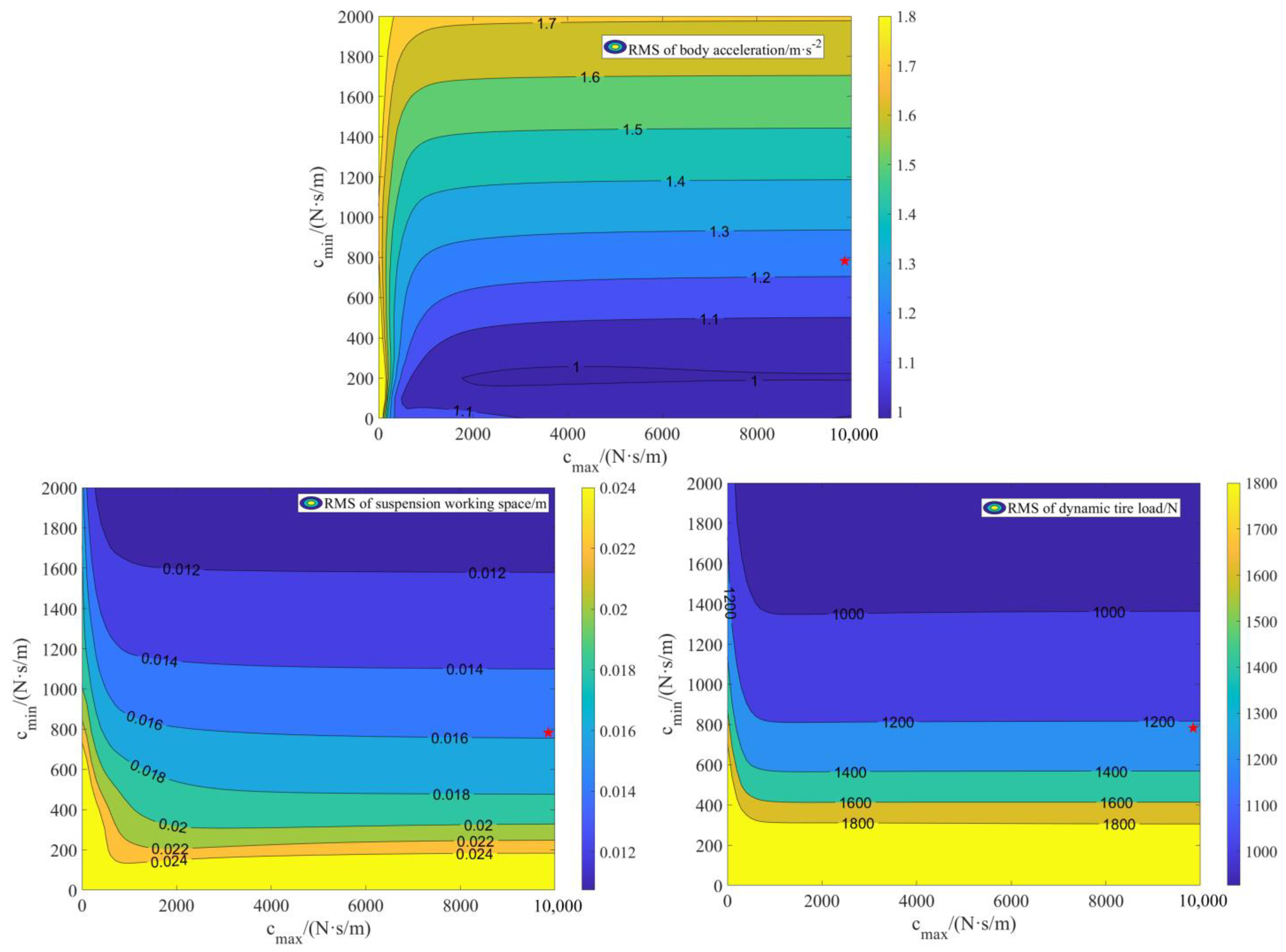
4.1. Influence of Damping Coefficient Variation on Dynamic Performance

The primary goal of the power-driven-damper control strategy is to regulate the damping adjustment in order to improve the dynamic performance of the suspension. In order to further study the action mechanism of the power-driven-damper vehicle ISD suspension, this study analyzes the influence of the damping coefficient on body acceleration, suspension working space, and dynamic tire load. The maximum damping coefficient cmax and the minimum damping coefficient cmin of the power-driven-damper control strategy are set at 0–10,000 N·s/m and 0–2000 N·s/m, respectively, and this analysis is based on the optimized suspension structure parameters. The simulation results are shown in Figure 4, where the star symbol represents optimal value point.
From Figure 4, it can be seen that, as the cmin increases, the RMS of body acceleration initially decreases and then increases. As the cmax increases, the RMS of body acceleration gradually decreases. Therefore, when the cmin is around 200 N·s·m−1 and the cmax reaches the upper limit, the RMS of body acceleration is minimum. However, we need to consider that the RMS of suspension working space and the dynamic tire load are both within an acceptable range. For the variation of the RMS of suspension working space, as cmin increases, the RMS of suspension working space gradually decreases. As cmax increases, the RMS of suspension working space gradually decreases. Therefore, when both cmax and cmin reach the upper limit, the RMS of suspension working space is minimum. For the variation of the RMS of dynamic tire load, as the cmin increases, the RMS of dynamic tire load gradually decreases. As the cmax increases, the RMS of dynamic tire load rapidly decreases and then tends to converge. Therefore, when the cmin reaches the upper limit and the cmax is relatively large, the RMS of dynamic tire load is minimum.

4.2. Research on Vibration Suppression Mechanism in Wide Frequency Domain

Suspension S4 is selected as the research object, and the suspension structure parameters are set according to the optimized parameters in Table 2. The body acceleration gain of the S4 suspension is obtained through simulation, as shown in Figure 5. From Figure 5, it can be seen that in the low frequency range, the amplitude of the body acceleration gain for suspension S4 has significantly decreased compared to that of suspension S0. In the high frequency range, the amplitude of the body acceleration gain has also decreased to some extent. The body acceleration gain of suspension S4 is smaller than that of suspension S0 in the range of 0–15 Hz. It can be inferred that, by combining ISD suspension and power-driven-damper control strategy, the suspension can effectively inherit the low-frequency vibration suppression effect of ISD suspension and the high-frequency vibration suppression effect of the power-driven-damper control strategy. Thus, it can be concluded that the power-driven-damper vehicle ISD suspension has a broadband vibration suppression characteristic.

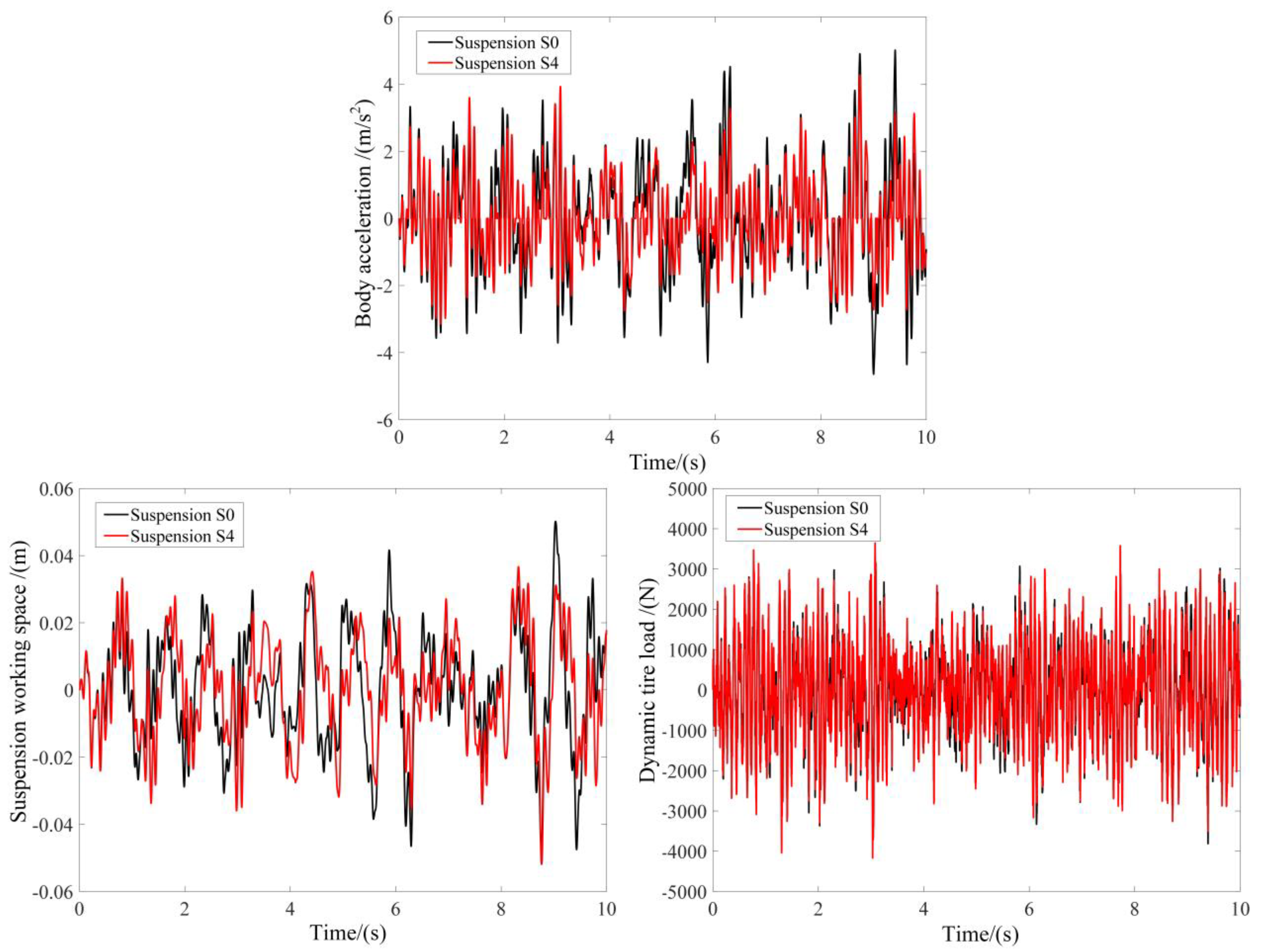
4.3. Time Domain Simulation

A random pavement model with a grade of C is selected as the input excitation, as shown in Equation (14). The simulation results of body acceleration, suspension working space, and dynamic tire load at a vehicle speed of 20 m/s are shown in Figure 6. From Figure 6, it is evident that suspension S4 exhibits significantly improved body acceleration performance compared to suspension S0 throughout the simulation period. Additionally, the suspension working space has also been improved to some extent. However, the dynamic tire load has deteriorated compared to the S0 suspension. This is due to sacrificing of dynamic tire load in order to improve body acceleration. However, the dynamic tire load still remains within a reasonable range.

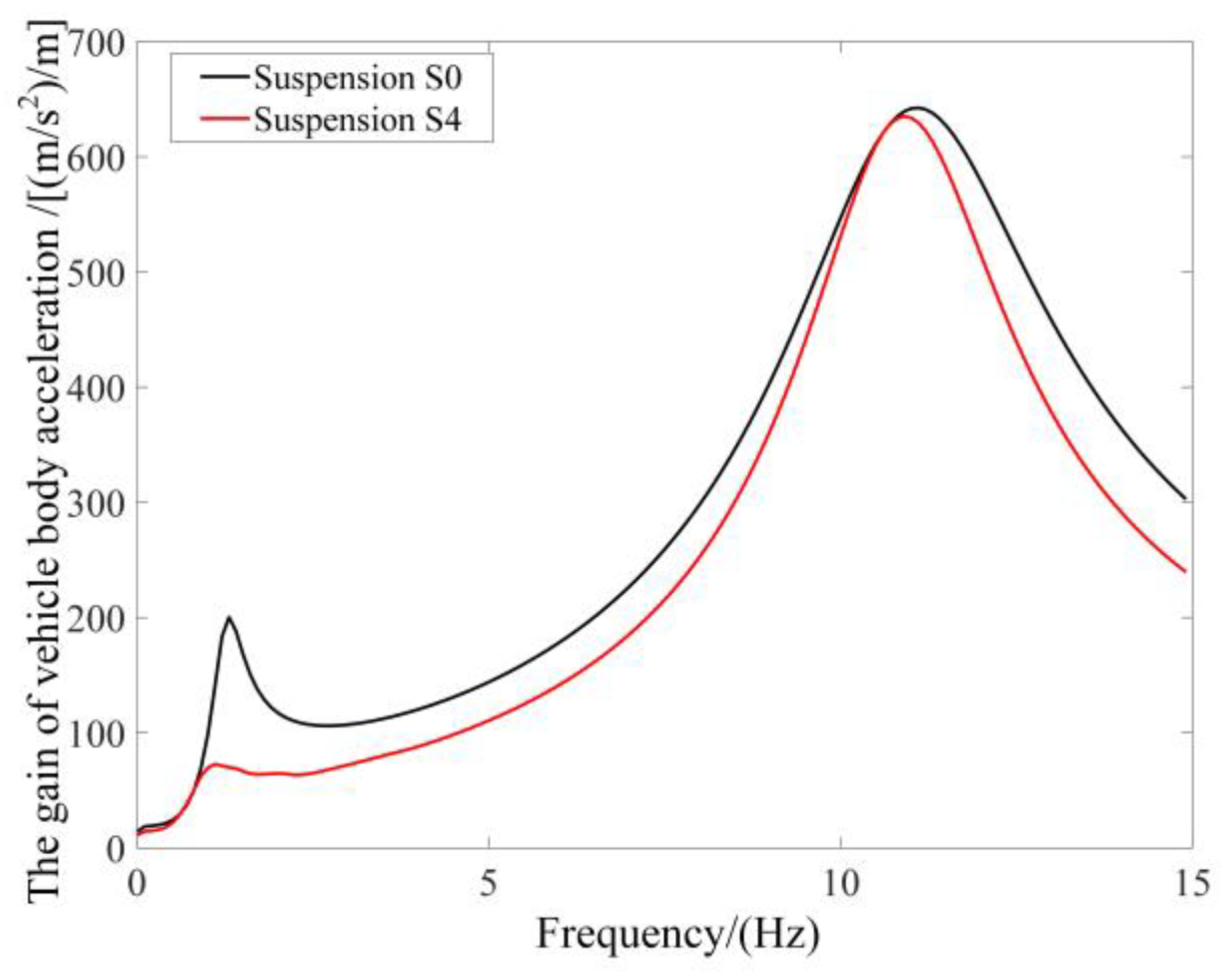
4.4. Frequency Domain Simulation

In order to further analyze the vibration suppression mechanism of power-driven-damper vehicle ISD suspension, Fourier series transformations are used to convert the time-domain diagram into the frequency-domain diagram, as shown in Figure 7.
From Figure 6, it can be seen that compared to suspension S0, the power spectral density of body acceleration of suspension S4 has improved in the 0–15 Hz range, with significant improvements in the low-frequency range of 5 Hz and below. This study examines the characteristics of power-driven-damper vehicle ISD suspension, which can improve body acceleration and suppress vibration over a broad frequency range. The power spectral density of suspension working space of suspension S4 deteriorates within the 1 Hz range but is nearly consistent with that of suspension S0 in the frequency band of 2 Hz and higher. However, there is a significant improvement between 1 Hz and 2 Hz. The power spectral density of dynamic tire load of Suspension S4 has significantly improved between 2 Hz and 4 Hz.

4.5. Discussion of the Results

From the above analysis, it can be seen that the RMS of body acceleration, suspension working space, and dynamic tire load are affected differently by the damping coefficient. However, the general trend indicates that body acceleration is inversely related to suspension working space and dynamic tire load. This means that while improving body acceleration, the other two performance indicators will deteriorate. The body acceleration gain of suspension S4 has been improved in the range of 0–15 Hz compared to suspension S0, which reflects the broadband vibration suppression characteristics of the power-driven-damper vehicle ISD suspension. The analysis in both the time-domain and frequency-domain shows that the body acceleration of suspension S4 is significantly improved compared to suspension S0. This improvement effectively enhances the ride comfort. The suspension S4 proposed in this paper effectively applies power-driven-damper control strategy to the ISD suspension. This approach achieves broadband vibration suppression and significantly improves body acceleration. In comparison to other suspensions, it achieves broadband vibration suppression without producing jitter.

5. Conclusions

In this paper, a quarter suspension model is established. Firstly, the expression of the power-driven-damper control strategy applied to vehicle ISD suspension is solved based on port-controlled Hamiltonian theory. Then, the suspension structure is topologically designed, four suspension structures are obtained, and the pigeon-inspired optimization is used to optimize the four structural parameters. Based on random road input, simulation results show that suspension S4 has reduced body acceleration by 23.1% compared to suspension S0, making it the most effective among all suspensions. This paper is comfort-oriented, and body acceleration directly affects the quality of riding comfort. Therefore, we selected suspension S4 as the research object. Based on the suspension S4, this study analyzes the impact of the damping coefficient on the performance of the power-driven-damper vehicle ISD suspension. We also analyze the variations in body acceleration gain and dynamic characteristics in both the time-domain and frequency-domain. The results show that, under the random input condition, the suspension S4 can decrease the RMS of body acceleration and the RMS of suspension working space by 23.1% and 6.6%, respectively, compared to the suspension S0 (traditional passive suspension), which effectively improves the ride comfort of the vehicle. The contour of body acceleration, suspension working space, and dynamic tire load reveal the impact of changes in damping coefficient on suspension dynamic performance. Both time-domain and frequency-domain analyses show that the power-driven-damper vehicle ISD suspension can effectively decrease body acceleration and significantly improve ride comfort.
The power-driven-damper vehicle ISD suspension designed in this paper achieves broadband vibration suppression without jitter associated with ADD control and without complex switching conditions. The variously designed structures lead to significant performance differences. The power-driven-damper vehicle ISD suspension, based on the optimum structure, significantly reduces body acceleration and effectively improves ride comfort. The optimization design method of suspension structures in this article presents new ideas for the structural design of suspensions. The broadband vibration suppression characteristics of the power-driven-damper vehicle ISD suspension offer a research direction for suppressing suspension vibration.
This paper exclusively focuses on conducting research using the quarter suspension model. However, it is also worth considering exploring high-dimensional dynamic models, such as the half vehicle and whole vehicle models. This article focuses solely on simulation analysis. Future research will include experiments to validate the simulation results.

Author Contributions

Conceptualization, Y.S.; methodology, X.Y.; software, J.W.; validation, J.W., F.D. and M.L.; formal analysis, F.D.; investigation, Y.S.; resources, M.L.; data curation, J.W.; writing—original draft preparation, J.W.; writing—review and editing, J.W.; visualization, Y.S.; supervision, X.Y.; project administration, Y.S.; funding acquisition, Y.S. All authors have read and agreed to the published version of the manuscript.

Funding

This research was funded by the National Natural Science Foundation of China under Grant 52002156 and 52072157, Postgraduate Research & Practice Innovation Program of Jiangsu Province (Grant No. SJCX22_1850) and Young Elite Scientists Sponsorship Program by CAST (No. 2022QNRC001).

Data Availability Statement

Data are contained within the article.

Acknowledgments

The authors would like to thank the editor and the anonymous reviewers for their careful reading and helpful comments.

Conflicts of Interest

Ming Li is employee of Weichai (Yangzhou) Yaxing New Energy Commercial Vehicle Co., Ltd. The paper reflects the views of the scientists, and not the company. The authors declare no conflicts of interest.

Abbreviation

AbbreviationMeaning
ISDInerter-Spring-Damper
PDDPower-driven-damper
ADDAcceleration-driven-damper
SHSkyhook
LQRLiner-quadratic-regulator

References

  1. Wen, X.; Li, Y.N.; Yang, C. Design, Modeling, and Characterization of a Tubular Linear Vibration Energy Harvester for Integrated Active Wheel System. Automot. Innov. 2021, 4, 413–429. [Google Scholar] [CrossRef]
  2. Sun, W.C.; Zhang, J.H.; Pan, H.H. Heavy vehicle air suspension control considering ride comfort and height regulation. Control Theory Appl. 2022, 39, 1002–1010. [Google Scholar]
  3. Qin, Y.Z.; Zhao, Z.; Wang, Z.F.; Li, G.F. Study of Longitudinal–Vertical Dynamics for In-Wheel Motor-Driven Electric Vehicles. Automot. Innov. 2021, 4, 227–237. [Google Scholar] [CrossRef]
  4. Issa, M.; Samn, A. Passive vehicle suspension system optimization using Harris Hawk Optimization algorithm. Math. Comput. Simul. 2021, 191, 328–345. [Google Scholar] [CrossRef]
  5. Kumar, S.; Medhavi, A.; Kumar, R. Optimization of Nonlinear Passive Suspension System to Minimize Road Damage for Heavy Goods Vehicle. Int. J. Acoust. Vib. 2021, 26, 56–63. [Google Scholar] [CrossRef]
  6. Abut, T.; Salkim, E. Control of Quarter-Car Active Suspension System Based on Optimized Fuzzy Linear Quadratic Regulator Control Method. Appl. Sci. 2023, 13, 8802. [Google Scholar] [CrossRef]
  7. Nie, J.; Wang, F.; Zhang, X.; Yang, Y. Design and test of hydro-pneumatic ISD suspension in heavy multi-axle vehicles. Adv. Mech. Eng. 2021, 13, 16878140211064737. [Google Scholar] [CrossRef]
  8. Wang, K.; Chen, M.Z.Q.; Li, C.; Chen, G. Passive Controller Realization of a Biquadratic Impedance with Double Poles and Zeros as a Seven-Element Series-Parallel Network for Effective Mechanical Control. IEEE Trans. Autom. Control 2018, 63, 3010–3015. [Google Scholar] [CrossRef]
  9. Li, F.J.; Li, X.P.; Shang, D.Y.; Wang, Z. Dynamic modeling and damping performance improvement of two stage ISD suspension system. Proc. Inst. Mech. Eng. Part D J. Automob. Eng. 2022, 236, 2259–2271. [Google Scholar] [CrossRef]
  10. Chen, L.; Zhang, X.L.; Nie, J.M.; Wang, R.C. Performance Analysis of Two-stage Series-connected Inerter-spring-damper Suspension Based on Half-car Model. J. Mech. Eng. 2012, 48, 102–108. [Google Scholar] [CrossRef]
  11. Du, F.; Mao, M.; Chen, Y.J.; Wang, Y.J.; Zhang, Y.F. Structure design and performance analysis of inerter-spring-damper suspension structure based on dynamic model and parameter optimization. J. Vib. Shock 2014, 33, 59–65. [Google Scholar]
  12. Xu, L.; Mao, M.; Chen, Y.J.; Du, F. Configuration Design and Analysis of two-stage tandem ISD suspension. J. Ordnance Equip. Eng. 2020, 41, 7–12. [Google Scholar]
  13. Nie, J.M.; Zhang, X.L.; Sun, X.Q.; Wang, R.C. Modeling and Parameter Optimization of a New Hybrid ISD Suspension. Automot. Eng. 2015, 2, 44–47. [Google Scholar]
  14. Paageorgiou, C.; Smith, M.C. Positive real synthesis using matrix inequalities for mechanical networks: Application to vehicle suspension. IEEE Trans. Control Syst. Technol. 2006, 14, 423–435. [Google Scholar] [CrossRef]
  15. Jiang, J.Z.; Smith, M.C. Series-Parallel Six-Element Synthesis of Biquadratic Impedances. IEEE Trans. Circuits Syst. I Regul. Pap. 2012, 59, 2543–2554. [Google Scholar] [CrossRef]
  16. Zhang, S.Y.; Jiang, J.Z.; Neild, S.A. Passive vibration control: A structure-immittance approach. Proc. R. Soc. A Math. Phys. Eng. Sci. 2017, 473, 20170011. [Google Scholar]
  17. Ioan-Cozmin, M.R.; Cornel, S.; Ioan, M. Analysis of passive vs. semi-active quarter car suspension model. In Proceedings of the Conference on Advanced Topics in Optoelectronics, Microelectronics and Nanotechnologies, Constanta, Romania, 20–23 August 2020; p. 11718. [Google Scholar]
  18. Jayaraman, T.; Palanisamy, S.; Thangaraj, M. Hydraulic control valve integrated novel semi active roll resistant interconnected suspension with vertical and roll coordinated control scheme. Proc. Inst. Mech. Eng. Part D-J. Automob. Eng. 2022, 237, 98–111. [Google Scholar] [CrossRef]
  19. Ma, T.; Bi, F.; Wang, X.; Tian, C.; Lin, J.; Wang, J.; Pang, G. Optimized Fuzzy Skyhook Control for Semi-Active Vehicle Suspension with New Inverse Model of Magnetorheological Fluid Damper. Energies 2021, 14, 1674. [Google Scholar] [CrossRef]
  20. Karnopp, D.; Crosby, M.J.; Harwood, R.A. Vibration control using semi-active force generators. J. Eng. Ind. 1974, 96, 619–626. [Google Scholar] [CrossRef]
  21. Karnopp, D.; Crosby, M.J. The active damper a new concept for shock and vibration control. Shock Vib. Bull. 1973, 143, 119–133. [Google Scholar]
  22. Zhu, B.L.; Qing, W.; ShangGuan, W.B.; Rakheja, S. Modeling and control of a quarter-car model with double wishbones and its equivalent two degrees of freedom model. J. Vib. Shock 2019, 10, 6–14. [Google Scholar]
  23. Lin, C.B.; Wang, Y.; Xu, E.Y.; Liu, F.Y.; Zhao, L.L.; Tang, Z.T. Study on improved ADD control Strategy for semi-active Suspensions. Noise Vib. Control 2023, 43, 197–202. [Google Scholar]
  24. Wang, Y.; Liu, F.Y.; Deng, J.C.; Zhao, L.L.; Tang, Z.T. Simulation Analysis of SH-LQR Damping Control Strategy for Semi-active Suspensions. Noise Vib. Control 2022, 42, 68–72. [Google Scholar]
  25. Savaresi, S.M.; Spelta, C. Mixed Sky-Hook and ADD: Approaching the Filtering Limits of a Semi-Active Suspension. J. Dyn. Syst. Meas. Control 2007, 129, 382–392. [Google Scholar] [CrossRef]
  26. Liu, Y.L.; Zuo, L. Mixed Skyhook and Power-Driven-Damper: A New Low-Jerk Semi-Active Suspension Control Based on Power Flow Analysis. J. Dyn. Syst. Meas. Control 2016, 138, 081009. [Google Scholar] [CrossRef]
  27. Morselli, R.; Zanasi, R. Control of port Hamiltonian systems by dissipative devices and its application to improve the semi-active suspension behaviour. Mechatronics 2008, 18, 364–369. [Google Scholar] [CrossRef]
  28. Talebitooti, R.; Gohari, H.D.; Zarastvand, M.R. Multi objective optimization of sound transmission across laminated composite cylindrical shell lined with porous core investigating Non-dominated Sorting Genetic Algorithm. Aerosp. Sci. Technol. 2017, 69, 269–280. [Google Scholar] [CrossRef]
  29. Qiu, H.X.; Duan, H.B. Multi-objective pigeon-inspired optimization for brushless direct current motor parameter design. Sci. China-Technol. Sci. 2015, 58, 1915–1923. [Google Scholar] [CrossRef]
  30. Sun, X.Q.; Chen, L.; Wang, S.H. Nonlinear modeling and parameter optimization of two-stage series ISD suspension. Trans. Chin. Soc. Agric. Mach. 2014, 45, 7–13. [Google Scholar]
  31. Liu, Y.L.; Yan, L.; Yang, X.F.; Shen, Y.; Liu, C. Optimization design and performance of vehicle ISD suspension based on ADD positive real network. J. Vib. Shock 2021, 40, 262–268. [Google Scholar]
Figure 1. Quarter suspension model.
Wevj 15 00008 g001
Figure 2. Four suspension structures.
Wevj 15 00008 g002
Figure 3. Algorithm flow chart.
Wevj 15 00008 g003
Figure 4. Dynamic performance contour map.
Wevj 15 00008 g004
Figure 5. Gain of body acceleration comparison diagram.
Wevj 15 00008 g005
Figure 6. Time-domain comparison of suspension performance.
Wevj 15 00008 g006
Figure 7. Frequency-domain comparison of suspension performance.
Wevj 15 00008 g007
Table 1. Passenger of car parameter.
ParametersSymbolUnitValue
Sprung massmskg320
Unsprung massmukg45
Support spring stiffnessKN·m−122,000
Damper coefficientCN·s·m−11000
Tire stiffnessktN·m−1190,000
Speed of vehicleum·s−120
Grade C Road roughness coefficientGq(n0)m3·cycle−12.56 × 10⁻⁴
Table 2. The results of the optimal design.
LayoutsOptimized ParametersJ1J2J3
S0k1 = 22,000, C = 10001.6070.01691150.3
S1k1 = 15,160, b = 16,
cmax = 9293, cmin = 1025
1.4247(11.4%↓)0.0139(17.8%↓)1216.7
S2k1 = 15,337, k2 = 2544, b = 5, cmax = 9617, cmin = 7501.3883(13.7%↓)0.0152(9.5%↓)1216.7
S3k1 = 15,128, k2 = 9814, k3 = 2122, b = 1936, cmax = 9817, cmin = 7771.2986(20.0%↓)0.0163(3.6%↓)1216.7
S4k1 = 15,011, k2 = 7424, k3 = 9778, k4 = 5, b = 3665, cmax = 9961, cmin = 7881.2359(23.1%↓)0.0158(6.6%↓)1216.7
Disclaimer/Publisher’s Note: The statements, opinions and data contained in all publications are solely those of the individual author(s) and contributor(s) and not of MDPI and/or the editor(s). MDPI and/or the editor(s) disclaim responsibility for any injury to people or property resulting from any ideas, methods, instructions or products referred to in the content.

