
Circulating Current Suppression Strategy Based on Virtual Impedance and Repetitive Controller for Modular Multilevel Converter Upper and Lower Bridge Arm Capacitance Parameter Asymmetry Conditions

Abstract
:1. Introduction
2. MMC Analysis
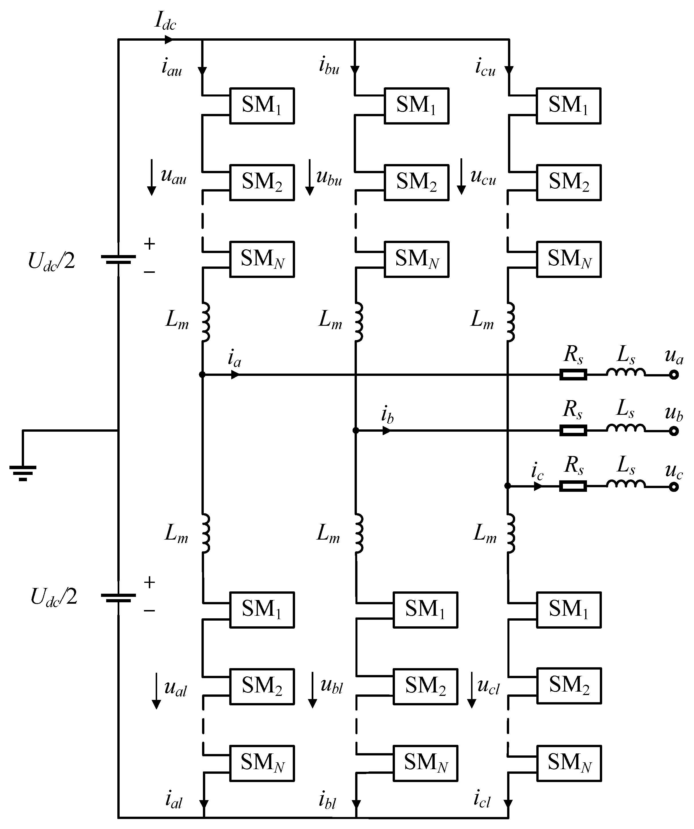
2.1. MMC Basic Circuit
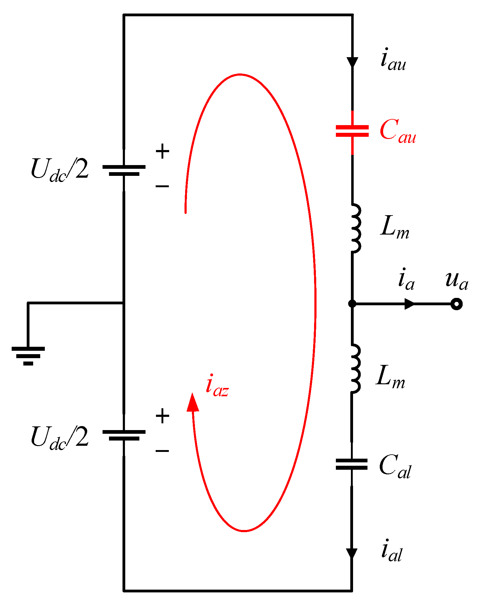
2.2. Circulating Current Analysis
- (1)
- The capacitors in the upper bridge arm of the A-phase deteriorate and their capacitance values all drop to 1/1 − n (n ≤ 0) times their rated value;
- (2)
- The remaining parameters, such as the inductance, remain symmetrical between the upper and lower bridge arms;
- (3)
- The capacitor voltage balancing control algorithm remains in effective operation and the average capacitor voltage remains stable.
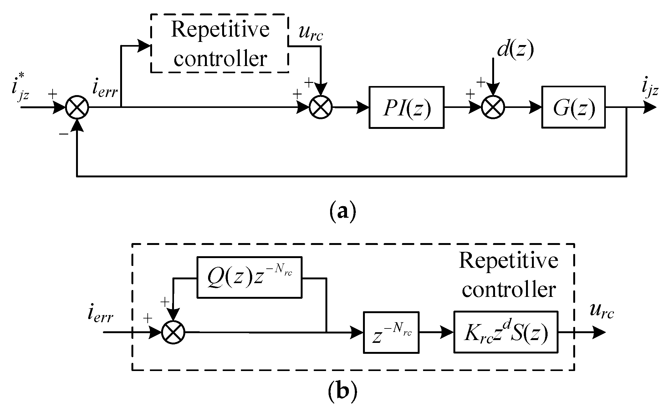
3. Circulating Current Suppression Strategy
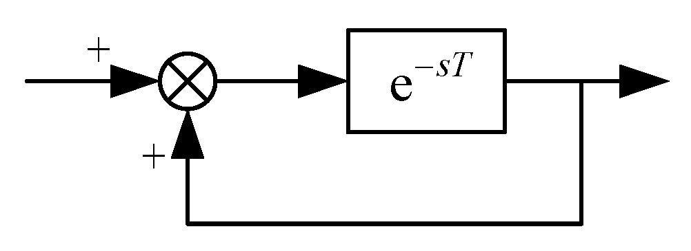
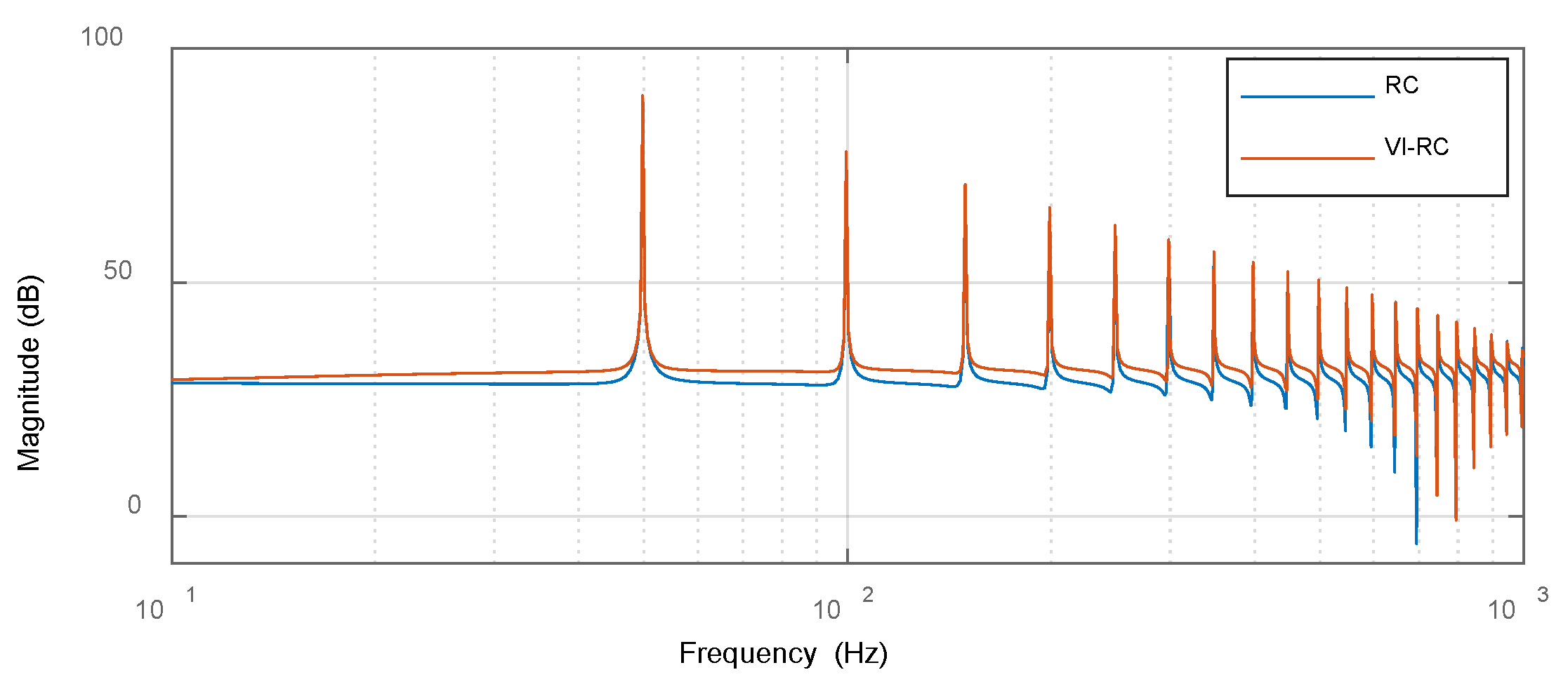
3.1. Repetitive Controller Design
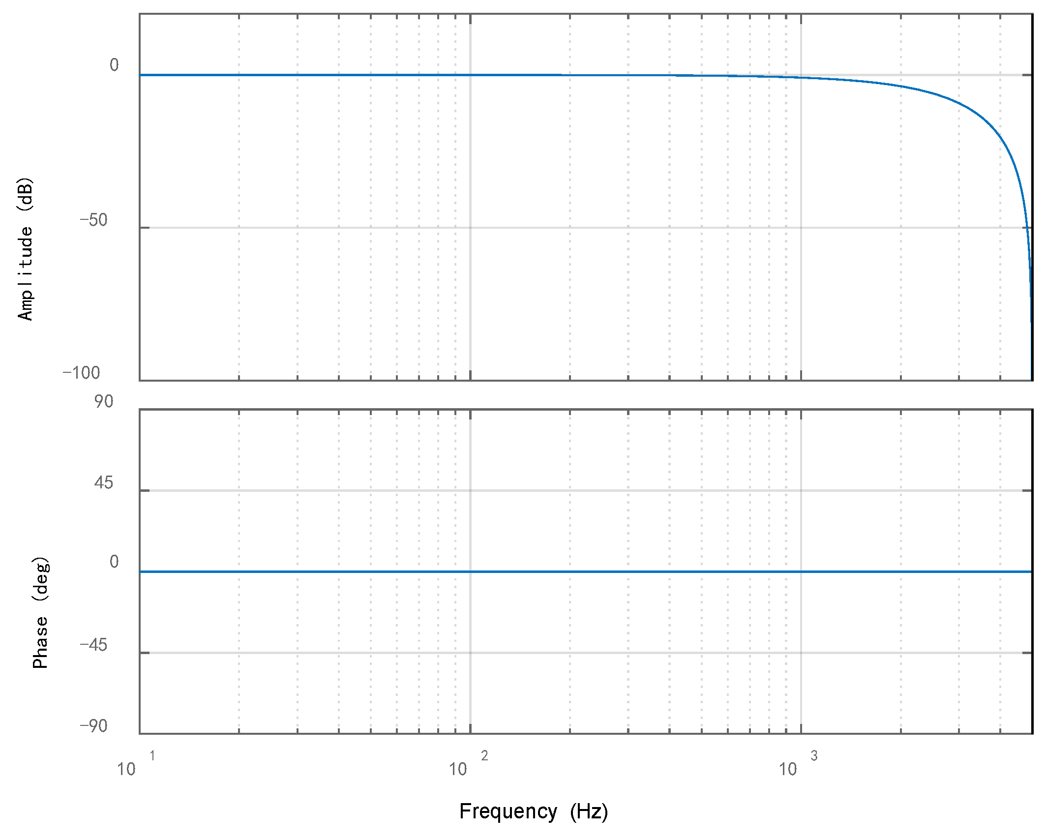
- (1)
- Low-pass filter
- (2)
- Time-delay session
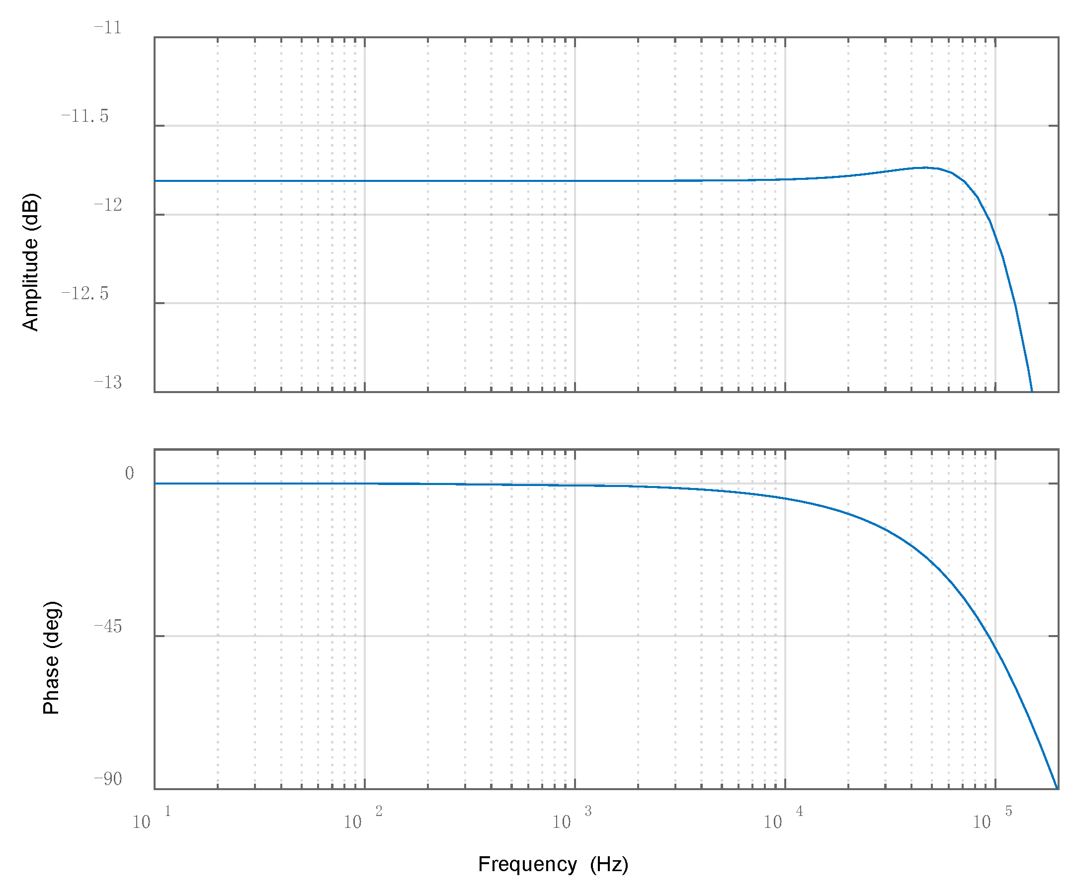
- (3)
- Compensation session
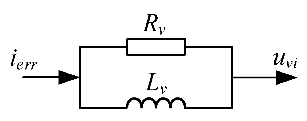
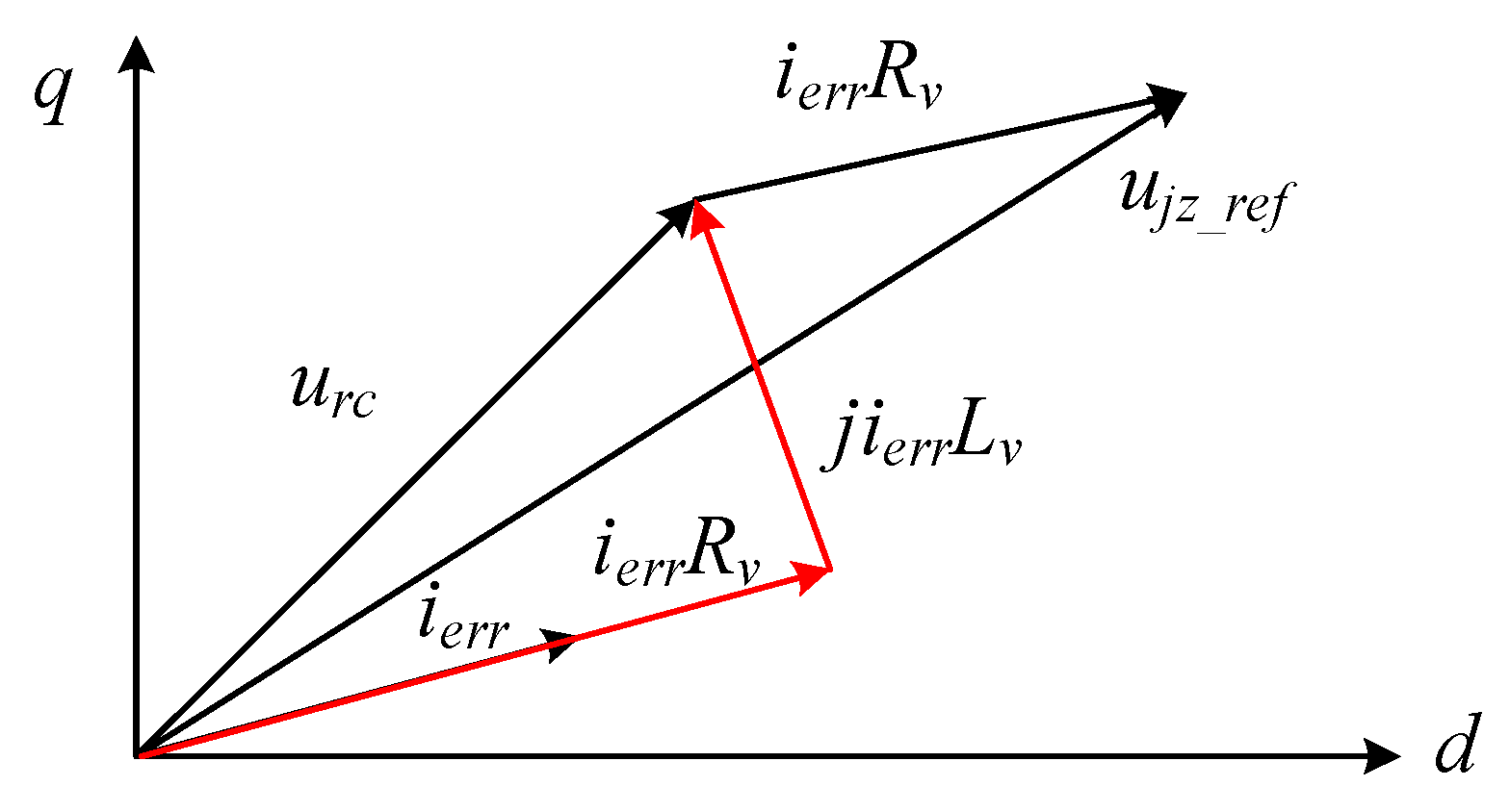
3.2. Additional Virtual Impedance Design
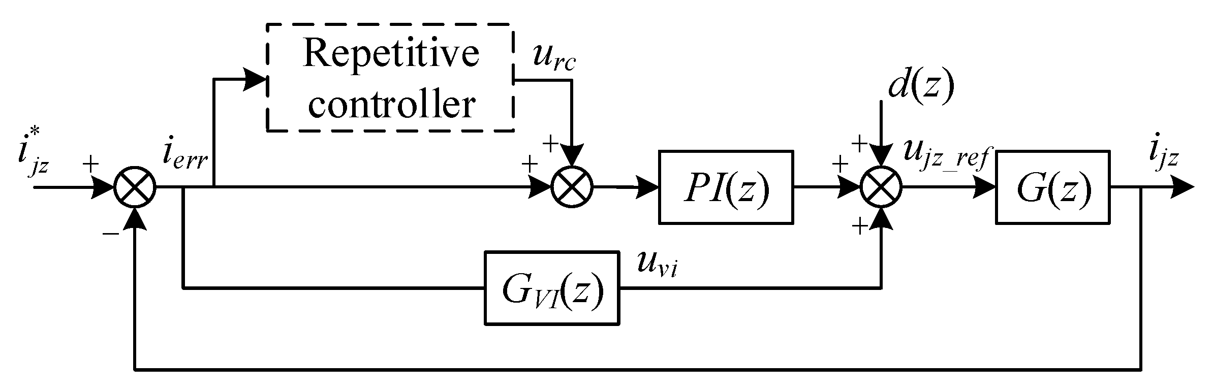
3.3. VI-RC Structure
4. Simulation Studies
4.1. Simulation Parameters
4.2. Simulation Results
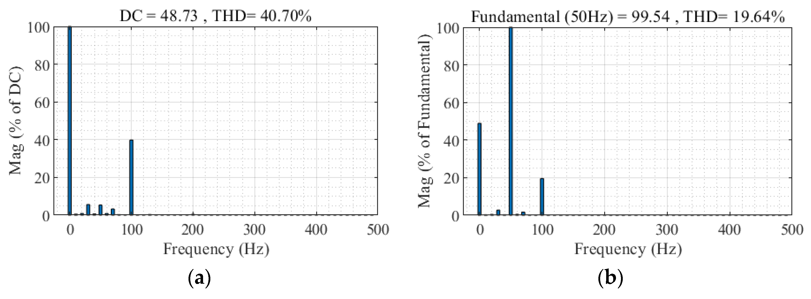
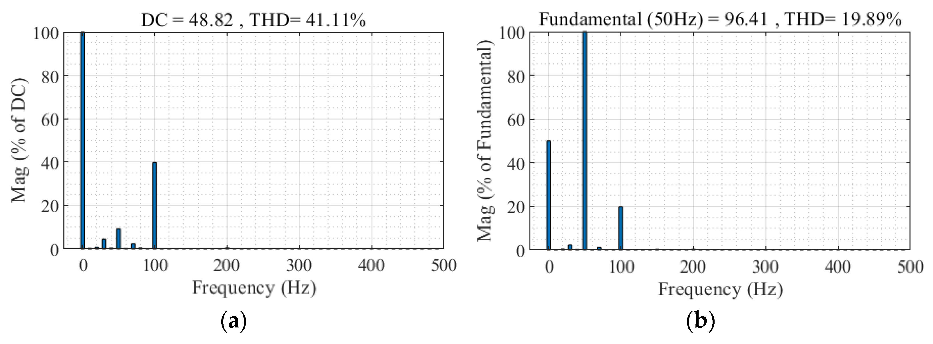
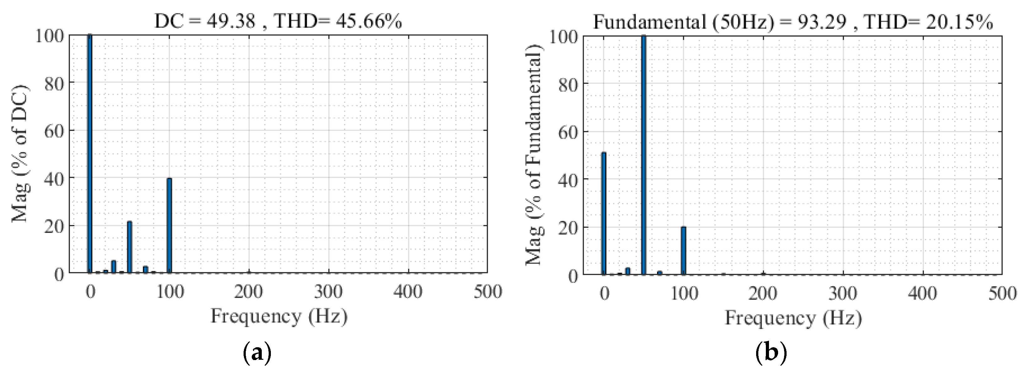
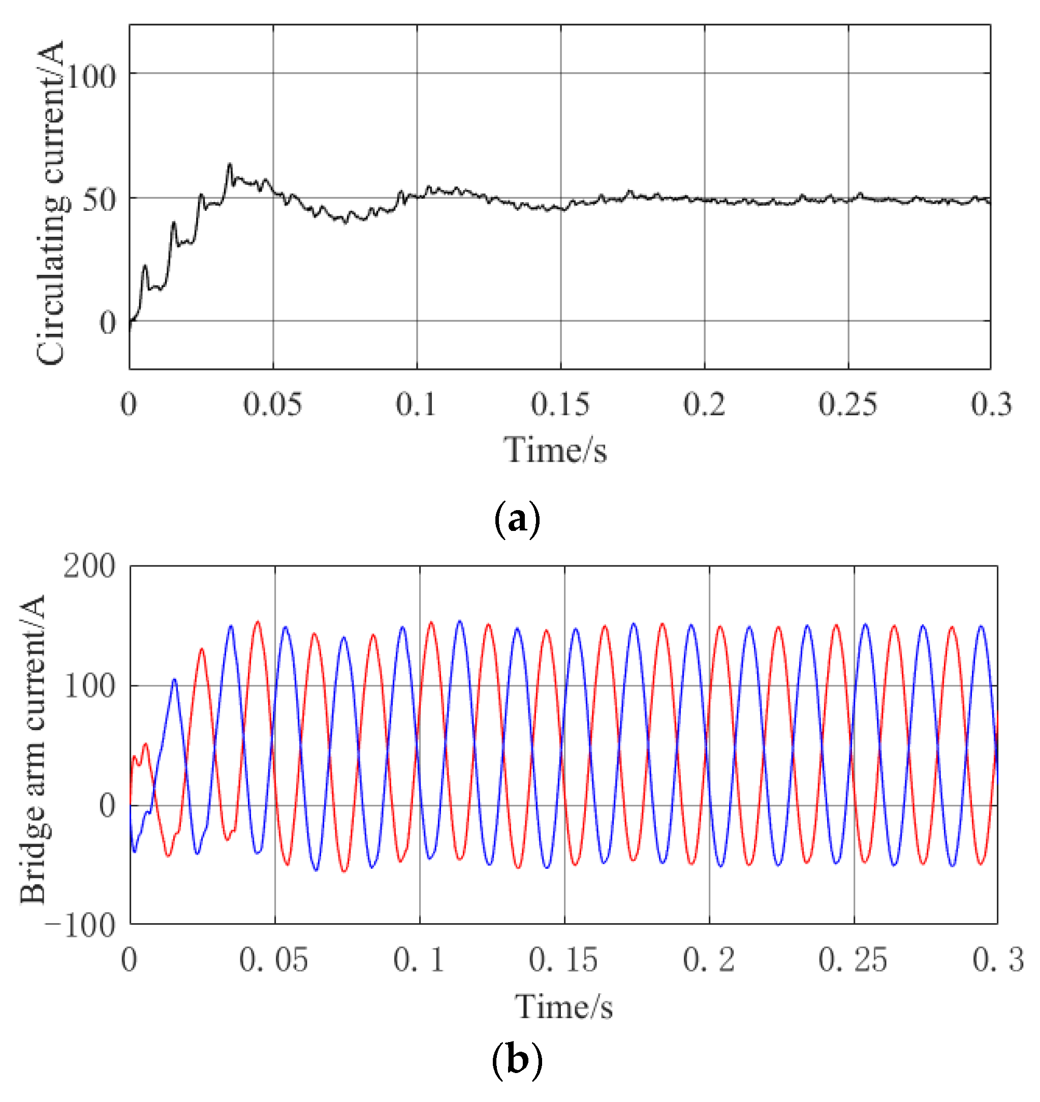
4.2.1. Circulating Current Characteristics
- (1)
- Condition 1: The capacitance rating of the upper bridge arm SMs of the A-phase is set to 7 mF and the capacitance rating of the lower bridge arm SMs is set to 7 mF;
- (2)
- Condition 2: The capacitance rating of the upper bridge arm SMs of A-phase is set to 6.5 mF and the capacitance rating of the lower bridge arm SMs is set to 7 mF;
- (3)
- Condition 3: The capacitance rating of the upper bridge arm SMs of A-phase is set to 6 mF and the capacitance rating of the lower bridge arm SMs is set to 7 mF.
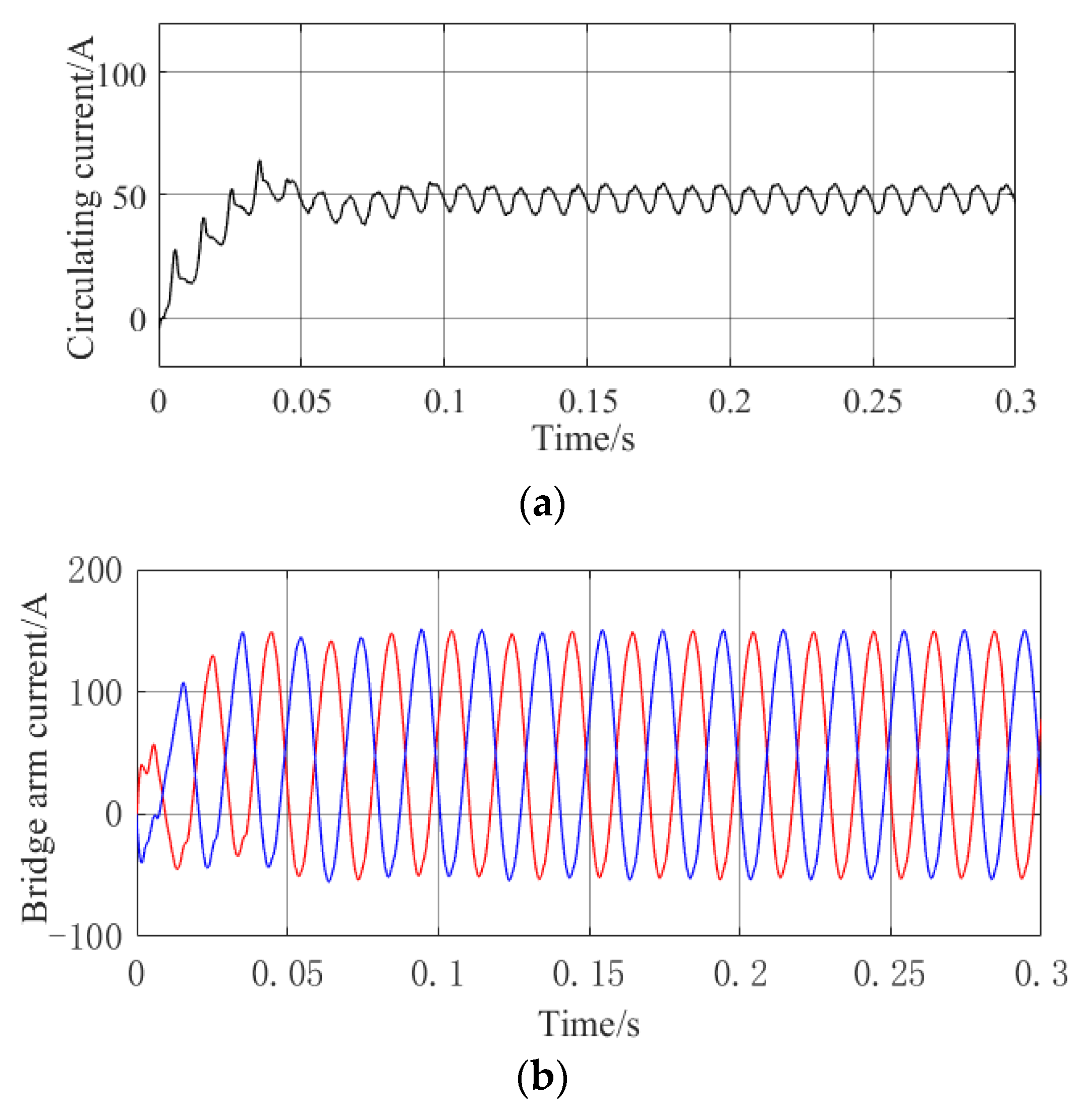
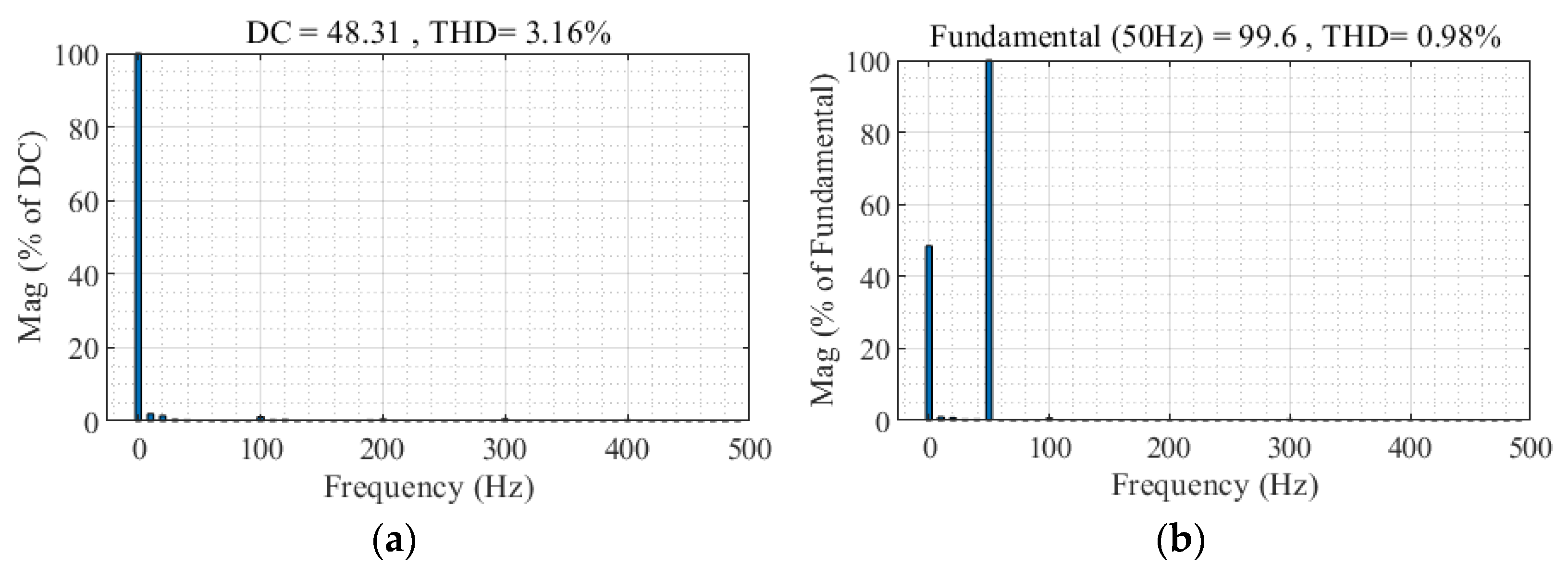
4.2.2. VI-RC Control Effect
4.2.3. Comparison of the Control Effects
- (1)
- PI controller
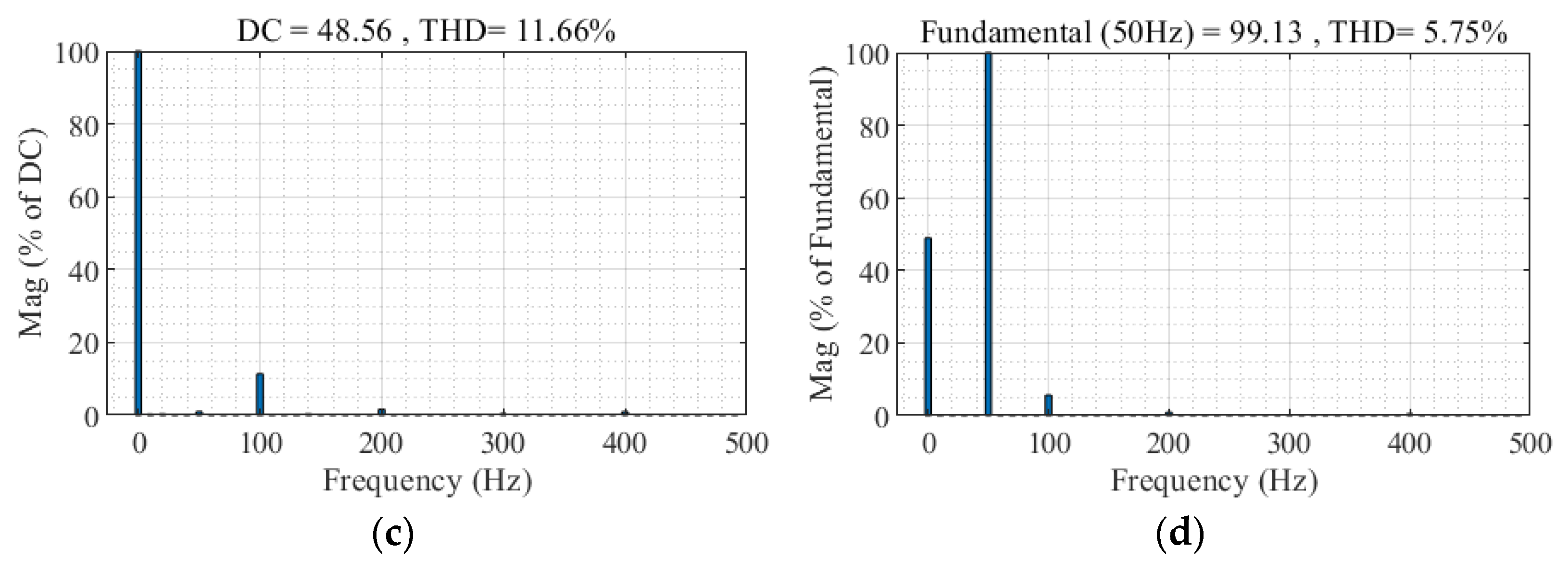
- (2)
- QPR controller
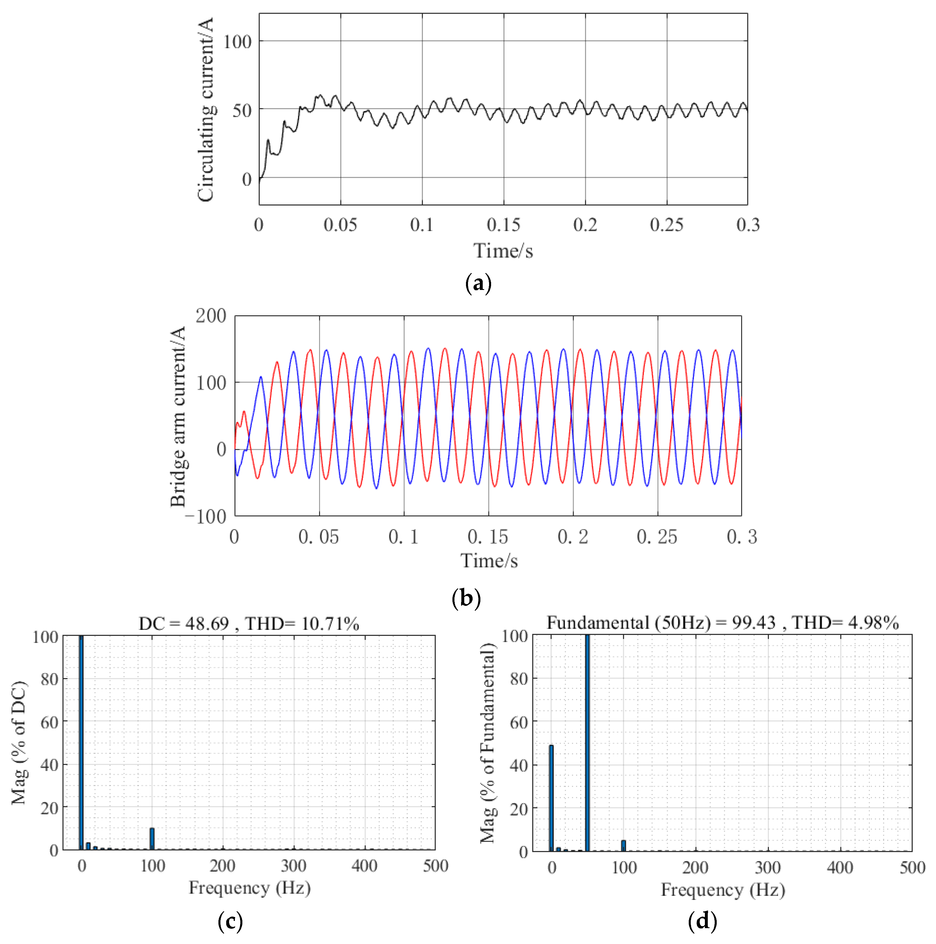
- (3)
- Repetitive controller
5. Discussion
6. Conclusions
Author Contributions
Funding
Data Availability Statement
Conflicts of Interest
References
- Mao, M.; Ding, Y.; Chang, L.; Hatziargyriou, N.D.; Chen, Q.; Tao, T.; Li, Y. Multi-Objective Power Management for EV Fleet With MMC-Based Integration Into Smart Grid. IEEE Trans. Smart Grid 2017, 10, 1428–1439. [Google Scholar] [CrossRef]
- Su, Y.-C.; Li, H.-M.; Chen, P.-L.; Cheng, P.-T. Integration of PV Panels and EV Chargers on the Modular Multilevel Converter Based SST. IEEE Trans. Ind. Appl. 2022, 58, 6428–6437. [Google Scholar] [CrossRef]
- Gan, C.; Sun, Q.; Wu, J.; Kong, W.; Shi, C.; Hu, Y. MMC-Based SRM Drives With Decentralized Battery Energy Storage System for Hybrid Electric Vehicles. IEEE Trans. Power Electron. 2018, 34, 2608–2621. [Google Scholar] [CrossRef]
- Sun, G.; Yin, X.; Lai, J.; Wang, Z.; Du, Y. Fault-tolerant control strategy of modular multilevel DC transformer. Trans. China Electrotech. Soc. 2022, 37, 246–287. [Google Scholar]
- Yang, X.; Li, Z.; Zhen, Q. A novel circulating current suppressing strategy based on virtual impedance sliding mode control. Proc. CSEE 2018, 12, 6893–6905. [Google Scholar]
- Deng, F.; Heng, Q.; Liu, C.; Wang, Q.; Zhu, R.; Cai, X.; Chen, Z. Power Losses Control for Modular Multilevel Converters Under Capacitor Deterioration. IEEE J. Emerg. Sel. Top. Power Electron. 2019, 8, 4318–4332. [Google Scholar] [CrossRef]
- Geng, Z.; Han, M.; Xie, W.; Sun, T. A Hierarchic Capacitor Condition Monitoring Strategy for High-Voltage Modular Multilevel Converters. IEEE Trans. Power Deliv. 2022, 37, 5310–5324. [Google Scholar] [CrossRef]
- Dong, P.; Lv, J.; Cai, X. Operation and control of modular multilevel converters under asymmetric arm parameter conditions. Proc. CSEE 2017, 37, 7255–7265. [Google Scholar]
- Zhang, J.; Shao, S.; Li, Y.; Zhang, J.; Sheng, K. Arm voltage balancing control of modular multilevel resonant converter. CES Trans. Electr. Mach. Syst. 2020, 4, 303–308. [Google Scholar] [CrossRef]
- Liang, Y.; Liu, J. Arm current control strategy for MMC-HVDC under harmonic and unbalanced grid voltages. Power Syst. Technol. 2018, 42, 2494–2502. [Google Scholar]
- Liu, Z.; Zhang, J.; Shi, G.; Zhou, J.; Zhang, Y.; Cai, X. An embedded DC power flow controller based on modular multilevel converter and its control strategy. Proc. CSEE 2022, 42, 7170–7182. [Google Scholar]
- Li, K.; Zhao, Z.; Yuan, L. Repetitive control of circulating current in MMC with asymmetrical operation of upper and lower arms. Trans. China Electrotech. Soc. 2016, 31, 122–129. [Google Scholar]
- Li, Y.; Jones, E.A.; Wang, F. Circulating Current Suppressing Control’s Impact on Arm Inductance Selection for Modular Multilevel Converter. IEEE J. Emerg. Sel. Top. Power Electron. 2016, 5, 182–188. [Google Scholar] [CrossRef]
- Li, B.; Xu, Z.; Shi, S.; Xu, D.; Wang, W. Comparative Study of the Active and Passive Circulating Current Suppression Methods for Modular Multilevel Converters. IEEE Trans. Power Electron. 2017, 33, 1878–1883. [Google Scholar] [CrossRef]
- Heng, Q.; Deng, F.; Liu, C.; Wang, Q.; Chen, J. Circulating Current Control Scheme Under Capacitor Aging in Modular Multilevel Converter. In Proceedings of the 8th Renewable Power Generation Conference (RPG 2019), Shanghai, China, 24–25 October 2019; pp. 1–7. [Google Scholar] [CrossRef]
- Wu, W.; Wu, X.; Jing, L.; Liu, J.; Wang, S.; Li, J. Circulating current suppressing strategy of modular multilevel converter in sub-module fault-tolerant control mode based on virtual resistor. Electr. Power Autom. Equip. 2018, 38, 161–168. [Google Scholar]
- Chen, Z.; Zhang, X.; Liu, C.; Zhang, H.; Luo, G. Research on current decoupling and harmonic suppression strategy of permanent magnet synchronous motor based on proportional resonance type ADRC. Proc. CSEE 2022, 42, 9062–9072. [Google Scholar]
- Lin, L.; He, J.; Xu, C. Analysis on Circulating Current and Split Capacitor Voltage Balance for Modular Multilevel Converter Based Three-phase Four-wire Split Capacitor DSTATCOM. J. Mod. Power Syst. Clean Energy 2021, 9, 657–667. [Google Scholar] [CrossRef]
- Li, Y.; Huang, X.; Xia, Z.; Li, P. Research on suppression strategy of low frequency subharmonics of grid-connected inverter based on PIR. Acta Energiae Solaris Sin. 2022, 43, 32–40. [Google Scholar]
- Nami, A.; Liang, J.; Dijkhuizen, F.; Demetriades, G.D. Modular Multilevel Converters for HVDC Applications: Review on Converter Cells and Functionalities. IEEE Trans. Power Electron. 2015, 30, 18–36. [Google Scholar] [CrossRef]
- Wu, X.; Wu, W.; Jing, L.; Li, J. Operation characteristics and the fault-tolerant control strategy of modular multilevel converter under sub-module faults. High Volt. Eng. 2016, 42, 3083–3091. [Google Scholar]
- Luo, Y.; Li, Q.; Huang, P.; Song, Y.; Jia, Z.; Wang, Q. Loss balanced control strategy for MMC considering bypassed sub-modules. Proc. CSEE 2022, 1–12. [Google Scholar]
- Lai, J.; Yin, X.; Wang, Y.; Yu, J.; Wang, K.; Liang, J. Improved capacitor voltage balancing control strategy for modular multilevel converter with arm current control. High Volt. Eng. 2022, 48, 3132–3145. [Google Scholar]
- Lan, Z.; Hao, R.; Jiao, H.; You, H. Optimal preview control of three-phase inverter based on repetitive control and state-feedback. Trans. China Electrotech. Soc. 2022, 37, 1473–1481. [Google Scholar]
- Yang, Q.; Wu, L.; Yan, Q.; Lin, Z. Discrete-time sliding mode multi-periodic repetitive control with reaching law based on dis-turbance compensation. Control Decis. 2023, 38, 421–428. [Google Scholar]
- Zhu, M.; Ye, Y.; Zhao, Q. A design Method of Repetitive Controller Against Variation of Grid Frequency. Proc. CSEE 2016, 36, 3857–3868. [Google Scholar]
- Meng, X.; Jia, Y.; Ren, C.; Han, X.; Wang, P. Modular circulating current and second harmonic current suppression strategy by virtual im-pedance for DC solid-state transformer. IEEE Trans. Power Electron. 2021, 36, 11921–11933. [Google Scholar] [CrossRef]
- Wang, C.; Yan, W.; Wang, W.; Ni, H.; Chu, J. The Suppression of Modular Multi-Level Converter Circulation Based on the PIR Virtual Impedance Strategy. World Electr. Veh. J. 2023, 14, 17. [Google Scholar] [CrossRef]
- Kong, F.; Zhou, J.; Mao, D.; Zhou, A.; Li, Y. Control circulating current suppressing strategy of MMC-BESS based on virtual impedance and passive backstepping control. South. Power Syst. Technol. 2022, 16, 104–112. [Google Scholar]
- Yang, X.; Li, Z.; Zheng, T.Q.; You, X.; Kobrle, P. Virtual Impedance Sliding Mode Control-Based MMC Circulating Current Suppressing Strategy. IEEE Access 2019, 7, 26229–26240. [Google Scholar] [CrossRef]


| Simulation Variable | Parameter Setting |
|---|---|
| Rated power/MW | 0.8 |
| DC bus voltage/kV | 5.5 |
| Number of SMs per arm | 22 |
| Rated submodule capacitance/mF | 7 |
| Arm inductance/mH | 1.35 |
| System sampling frequency/kHz | 10 |
| Controller Parameters | Parameter Setting |
|---|---|
| Nrc | 200 |
| Krc | 1 |
| Kp | 30 |
| Ki | 1 |
| d | 4 |
| Rv/Ω | 1 |
| Lv/mH | 10 |
| Condition | Fundamental Frequency Amplitude/A | Second Frequency Amplitude/A | THD of Bridge Arm Current/% |
|---|---|---|---|
| Condition 1 | 2.63 | 19.38 | 19.64 |
| Condition 2 | 4.49 | 19.39 | 19.89 |
| Condition 3 | 10.69 | 19.62 | 20.15 |
| Controller Use | Fundamental Frequency Amplitude/A | Second Frequency Amplitude/A | THD of Bridge Arm Current/% |
|---|---|---|---|
| No controller | 4.49 | 19.39 | 19.89 |
| PI | 0.48 | 5.53 | 5.75 |
| QPR | 0.16 | 4.87 | 5.23 |
| RC | 0.93 | 0.73 | 1.48 |
| VI-RC | 0.09 | 0.56 | 0.98 |
Disclaimer/Publisher’s Note: The statements, opinions and data contained in all publications are solely those of the individual author(s) and contributor(s) and not of MDPI and/or the editor(s). MDPI and/or the editor(s) disclaim responsibility for any injury to people or property resulting from any ideas, methods, instructions or products referred to in the content. |
© 2023 by the authors. Licensee MDPI, Basel, Switzerland. This article is an open access article distributed under the terms and conditions of the Creative Commons Attribution (CC BY) license (https://creativecommons.org/licenses/by/4.0/).
Share and Cite
Yao, M.; Ni, H.; Zhao, F.; Wang, W.; Yan, W. Circulating Current Suppression Strategy Based on Virtual Impedance and Repetitive Controller for Modular Multilevel Converter Upper and Lower Bridge Arm Capacitance Parameter Asymmetry Conditions. World Electr. Veh. J. 2023, 14, 181. https://doi.org/10.3390/wevj14070181
Yao M, Ni H, Zhao F, Wang W, Yan W. Circulating Current Suppression Strategy Based on Virtual Impedance and Repetitive Controller for Modular Multilevel Converter Upper and Lower Bridge Arm Capacitance Parameter Asymmetry Conditions. World Electric Vehicle Journal. 2023; 14(7):181. https://doi.org/10.3390/wevj14070181
Chicago/Turabian StyleYao, Mincheng, Hongyu Ni, Feng Zhao, Wenyuan Wang, and Wenxu Yan. 2023. "Circulating Current Suppression Strategy Based on Virtual Impedance and Repetitive Controller for Modular Multilevel Converter Upper and Lower Bridge Arm Capacitance Parameter Asymmetry Conditions" World Electric Vehicle Journal 14, no. 7: 181. https://doi.org/10.3390/wevj14070181
APA StyleYao, M., Ni, H., Zhao, F., Wang, W., & Yan, W. (2023). Circulating Current Suppression Strategy Based on Virtual Impedance and Repetitive Controller for Modular Multilevel Converter Upper and Lower Bridge Arm Capacitance Parameter Asymmetry Conditions. World Electric Vehicle Journal, 14(7), 181. https://doi.org/10.3390/wevj14070181