Review

Investigation of Effective Factors on Vehicles Integrated Photovoltaic (VIPV) Performance: A Review

Department of Engineering, University of Palermo, 90133 Palermo, Italy
*
Author to whom correspondence should be addressed.
World Electr. Veh. J. 2023, 14(6), 154; https://doi.org/10.3390/wevj14060154
Submission received: 16 May 2023 / Revised: 31 May 2023 / Accepted: 7 June 2023 / Published: 12 June 2023

Abstract

:
Integrating photovoltaic technology has undergone significant development in recent years, owing to its manifold advantages. One of the most recent domains where this technology has found application is within the transportation sector. The utilization of this technology possesses the potential to initiate a new revolution in transportation by enhancing the range and reducing fuel consumption in vehicles. The performance of these systems is influenced by numerous factors, which have been thoroughly examined in this study. These factors have been categorized into three broad groups: installation site, solar cell characteristics, and environmental conditions. It is important to note that these conditions are inherently interdependent, so this study reveals that the radiation incident on the roof of a van can be 1.09–3.85 times greater than the radiation incident on its sides, according to varying meteorological conditions and different seasons. The current research serves as a valuable foundation for future investigations in this field, offering a targeted and practical overview of the work conducted thus far and summarizing the current state of research.

1. Introduction

Environmental pollution and its damage to human life is the primary motivation for using renewable resources. A large percentage of this pollution is related to carbon emissions caused by the consumption of fossil fuels in vehicles [1]. According to statistics, more than 82 million different vehicles have been produced in 2021 [2], and the amount of direct carbon dioxide emissions from the combustion of fossil fuels in the transportation industry in 2021 singly is about 7.65 gigatons [3]. One of the essential solutions to reduce carbon emissions is the production and use of electric and hybrid vehicles instead of conventional vehicles that work with fossil fuels [4]. However, a fundamental problem of electric vehicles is the charging time and the number of times they are charged [5].
Vehicles are usually exposed to direct sunlight, and their body can be an excellent place to install photovoltaic cells [6]. With the progress achieved in the production and development process of photovoltaic cells, these cells can be integrated into the body of vehicles. This technology can fully or partially provide the required energy for electric vehicles [7]. In addition, this technology can reduce the number of recharging times and increase the vehicle’s range. As a suitable solution to produce electric energy needed by vehicles from a renewable and clean source and supply their energy, this technology can significantly contribute to the development of electric vehicle manufacturing and promote their use [8]. Despite the numerous advantages of photovoltaic technology, it is essential to acknowledge the various limitations that hinder its utilization in Vehicle-Integrated Photovoltaics (VIPV) applications. For instance, certain solar cell types, such as silicon, exhibit a considerable weight proportion attributed to the presence of glass. Additionally, some solar cells are susceptible to fragility. Consequently, these factors must be meticulously addressed when integrating photovoltaic systems into vehicles with intricate body geometries. However, it is worth noting that certain researchers have successfully tackled this challenge by devising innovative solutions [9,10].
Since transportation is an essential part of people’s daily life, accounting for many air pollution and carbon dioxide emissions [1,3], many researchers and industrial groups have investigated and developed vehicles integrated photovoltaics (VIPV). Many articles have been published on integrated photovoltaics of vehicles. Various researchers have categorized and introduced various types of VIPV systems [11], commercial products and laboratory samples in this field [12], methods of simulating and simplifying these systems, etc. The number of published papers between 2011 and 2023 about VIPV that were used in this research, can be seen in Figure 1.
Figure 2 shows the actual trend in the research on this topic. The clustering algorithm, based on the Scopus database, found that only 32 sources (journals and conferences) have a minimum of five documents. Only journals have been selected (22 journals). For each of the 22 journals, the total strength of the citation link is evaluated (publication and how many times is cited by). The dimension of the source depends on the number of documents (i.e., applied energy has 32, energies 42, energy 24). Finally, VOSviewer applied a clustering algorithm with five main clusters in different colors (i.e., cluster 1 is red and embraces Energy, Energies, Sustainability, IEEE Access, and lecture notes in electrical engineering, which have different mutual citations).
This work provides a comprehensive examination of recent research by scholars, focusing on the factors that influence the efficiency of integrated photovoltaic systems in vehicles. Firstly, an in-depth review of recent projects undertaken in this field is presented, considering the types of vehicles and modes of transportation. Subsequently, a detailed analysis of the challenges and potential associated with each case is conducted. In general, numerous factors contribute to energy production by solar cells installed on vehicles. However, this study categorizes explicitly and discusses the research activities carried out by scholars in three main domains: cell installation conditions, photovoltaic cell characteristics, and environmental/geographical conditions. The study delves into the impact of these factors on the efficiency of integrated photovoltaic systems, providing comparative analyses. This study will likely guide future research endeavors, enabling more focused and pragmatic approaches to further advancements in this field.

2. A Review of Vehicle-Integrated Photovoltaic

In recent years, the use of integrated photovoltaic systems in residential areas has become popular due to the increase in the density and population of cities in buildings and vehicles [13]. Among the positive points of this technology, it can be integrated into the body of buildings and vehicles [14]. Another positive point of this technology is that the generated electricity can be directly transferred to the car’s internal power grid and does not need a storage system [15]. This subject is the most crucial advantage of integrated solar vehicle systems compared to fixed parking lots equipped with solar cells [16,17,18,19]. However, due to being in a fixed position, solar parking lots can quickly receive the highest amount of incoming radiation using tracking systems [20,21,22,23]. While this is somewhat difficult in vehicles due to movement, in the present work, various solutions will be presented to increase the efficiency of these types of systems by examining the factors affecting the efficiency of these types of systems [24].
In general, many ideas have been presented in the development of vehicle-integrated photovoltaics and used in various applications, such as private cars [25], airplanes [26], buses [27,28], ships, and boats [29], trains [30], and trucks [31,32,33]. The energy produced by solar cells, depending on the vehicle type, can supply part of the electricity consumed by accessories (fan, air conditioner, audio player, etc.) or even help to increase the range and charge the battery in two modes: parking and movement [11]. For example, the electricity generated by solar cells in ships and yachts can be used for interior lighting at night, in food trucks to provide the electricity needed for refrigeration [31], and in vans and campers for air conditioning in the cabin. In cars that are lighter than others, it can even increase the driving distance and charge the batteries [12]. Of course, the energy produced by solar cells in each vehicle can be utilized in many other ways, and the mentioned items are just some examples of the various available applications. Another essential application of these systems is during natural disasters. Natural disasters, such as floods, earthquakes, etc., sometimes lead to power outages in households. Vehicles equipped with solar cells can be used as a source of electricity for families affected by natural disasters. For instance, in Japan in 2011, a truck equipped with 250 solar panels, each with a power of 20 watts (5 kilowatts), was used for this purpose [34].

3. Effecting Parameters on Vehicles’ Integrated Photovoltaic Performance

In general, many factors affect the efficiency and performance of integrated photovoltaic systems of vehicles [35]. Among these factors, we can mention the driving pattern, road conditions, atmospheric and climatic conditions, cell installation location, vehicle type, installed cell type, internal connections, etc. For example, the body of trucks has a simpler geometry than personal cars, and installing solar cells on it is less of a challenge [36]. On the other hand, there is a more usable surface area for installing photovoltaic cells on trucks. However, on the other hand, they have much weight, and due to their use for carrying loads, they consume much energy when moving [37]. For this reason, it may not be easy to fully supply its energy with the help of integrated photovoltaic systems. However, in personal light vehicles, considering their lower weight and their type of use, this seems more accessible. For example, in Figure 3a, the photovoltaic modules installed on the car body of Sion (a product of Sono Motors) and its weekly solar array can be seen. The power of silicon monocrystal cells used in the body of this car is 1200 WP. The results of Figure 3b are based on Munich, Germany, and separately from cloudy and precise weather conditions. According to these results, the range of the mentioned car in ideal conditions is 112 km per week on average, which can be increased to 245 km per week depending on the conditions [38]. The difference in solar range values in the season, weather conditions, and different situations show the impact of these factors on the efficiency of energy production by photovoltaic modules installed on vehicles.
According to the mentioned cases, many factors affect the performance of integrated photovoltaic systems of vehicles. Hence, studying and investigating the effect of these factors and knowing them is essential in designing these types of systems. For this reason, the research carried out in this field was analyzed in the present work by dividing it into three general sections, including installation site conditions, photovoltaic cell conditions, and environmental conditions.

3.1. Installation Position of PV

A large percentage of the vehicle body is exposed to sunlight, and for this reason, it has a very good potential for installing photovoltaic cells. As mentioned in the previous section, integrated photovoltaic cells can be integrated into the body of vehicles due to the variety of colors, shapes, and dimensions. Usually, in most VIPV projects, photovoltaic cells are integrated into the vehicle roof, because, here, researchers face fewer technical requirements and installation challenges than in other places [12]. However, with the advancement of technology and production technologies of photovoltaic cells, researchers and craftsmen have tried to make maximum use of the outer surface of vehicles and install integrated photovoltaic cells on different parts such as sides, hood, trunk, and even windows [39]. It is also possible to add solar cells in a portable form or as a desired part and as a side option, such as a canopy to boats and ships, spoilers of trucks, etc. Among the reasons for this is an increase in installed cells and, as a result, the increased efficiency of the VIPV system [33].
In Figure 3, the amount of incoming radiation of different levels of two cars can be seen in different conditions. The results of Figure 4a are related to the test of the assumed vehicle along a 36 km route in Hanover, Germany (51°59′ N, 9°31′ E) on 31 May 2021. The supposed car has been moving or stationary on this route in different time intervals, and the vertical gray lines are used to separate these intervals. On the body of this car, there are 15 amorphous silicon modules (five on the roof, four on each side, and two on the back) with a total power of 2180 Wp (the total power of the modules installed on the roof is 875 Wp and the modules installed on the side and back are 1305 Wp) with an area of about 11.6 square meters (including the space between the modules, this amount will be about 15 square meters) [39]. The graphs in Figure 4b show the results obtained from the pyranometers installed on a car in Miyazaki, Japan, along a 15 km route (31°49′ N, 131°24′ E). This test was conducted in clear and sunny weather on 28 July 2018 [40]. According to these diagrams, it can be claimed that the amount of radiation on the car’s roof is generally higher than on other parts of the car’s body. However, the amount of this difference may vary in different conditions. Since the incoming radiation, in addition to the location of the cell installation on the vehicle, depends on various other factors such as weather conditions, temperature, seasonal changes, etc. For example, according to the results of another test that was conducted during 2019–2020 on a 21 km route located in Hanover, Germany (52°22′28″ N 9°44′19″ E), the amount of incoming radiation on the roof of a van in different conditions can be between 1.09 and 3.85 times the incoming radiation to its sides [41].

3.2. PV Cell

Various types of solar cells, such as silicon crystal, thin film, multi-junction, semi-transparent cells, etc., have been introduced or used as options for integration into vehicle bodies. Each of the mentioned types of solar cells has different advantages and challenges for installation and integration in the body of vehicles [6]. For this reason, in this section, from four different aspects, the effect of geometry, material, type of internal electrical connections, and thermal factors on the performance of different solar cells has been investigated.

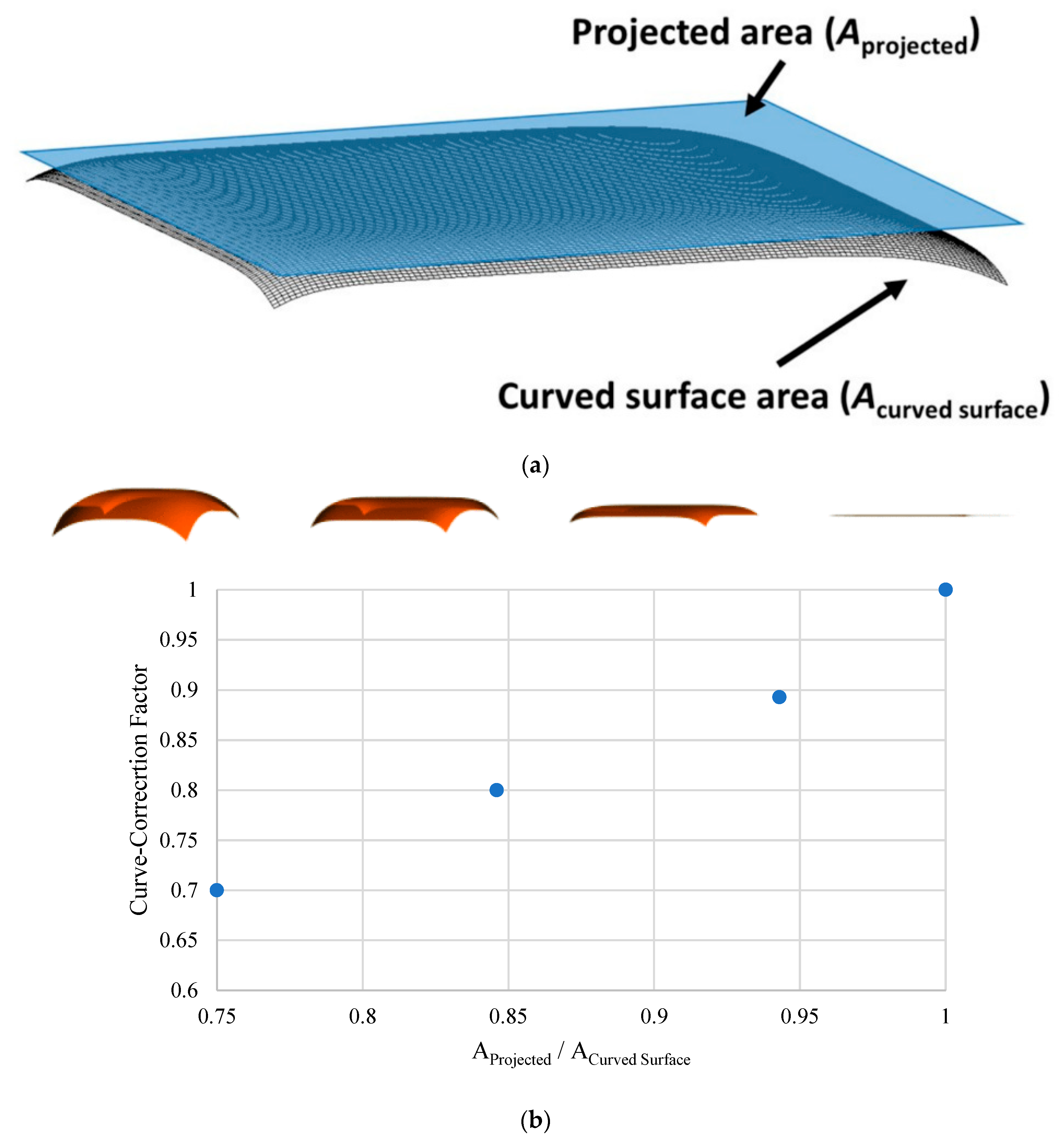
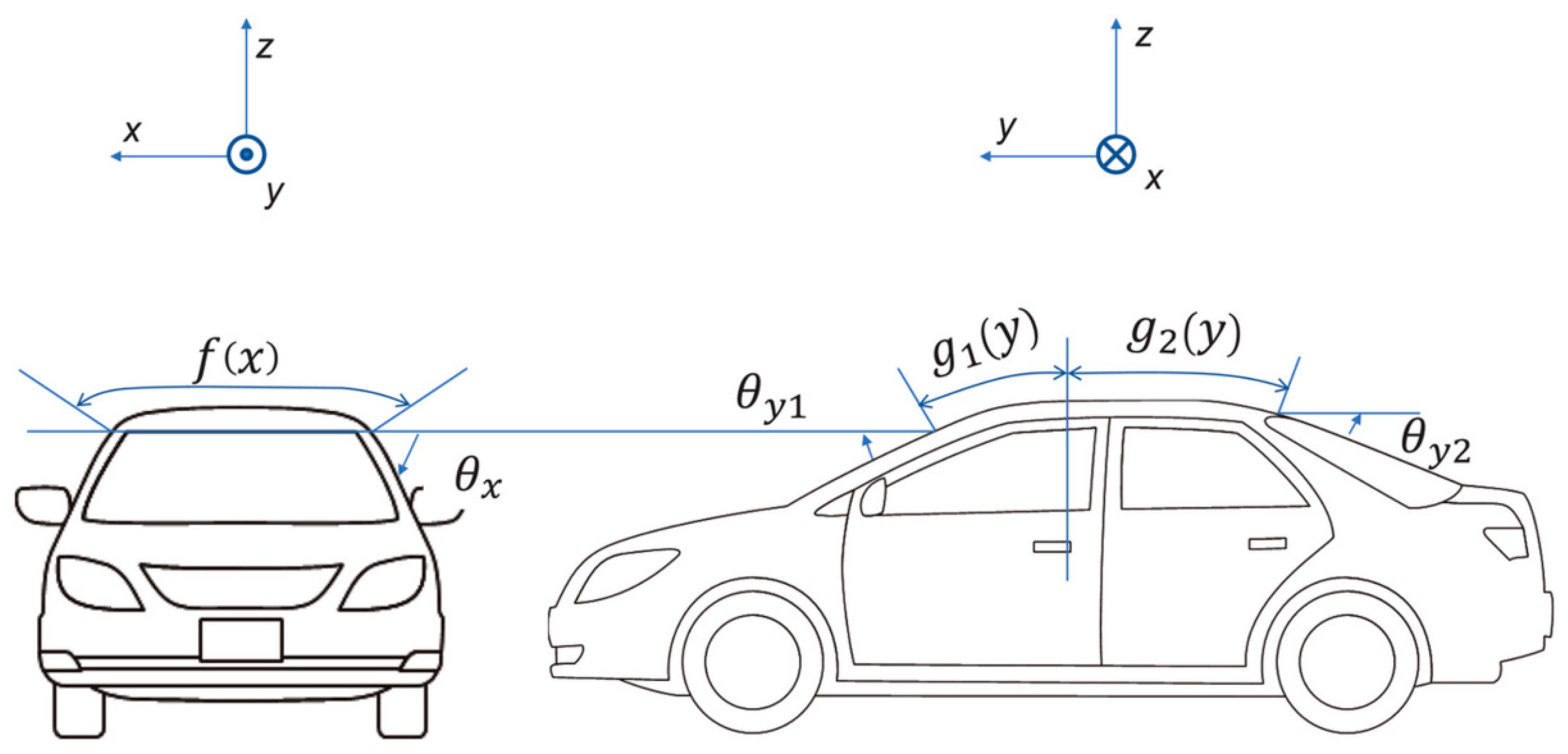
3.2.1. Shape and Geometry Design

The body of some vehicles, especially private cars, has a complex shape and many curves. Sometimes, in these conditions, using and installing solar cells on them is a big challenge. Additionally, this issue affects the efficiency of the solar cell and its output power. In general, the output power of a solar cell can be calculated from Equation (1) [42]:
P = η · I r r · A
Furthermore, by applying some changes in the formula of Equation (1), the power of photovoltaic curve modules can be calculated as follows [43]:
P = f · A C u r v e d   S u r f a c e · I r r r o o f · η P V
In this equation, f is the curve correction factor, A C u r v e d   S u r f a c e is the surface area of the curved module, I r r r o o f is the amount of radiation absorbed by the assumed car roof and η P V is the efficiency of the solar cell. All the mentioned items can be measured or pre-calculated, but the curve correction factor will be obtained from the following equation [44]:
f = f 1 f 2 f 3
In fact, this coefficient calculates the losses caused by the curvature of the vehicle body and its effect on the output power of the photovoltaic cell. In this equation, f 1 is the coverage factor, f 2 is the optical curve correction factor, and f 3 is the uneven expansion correction factor. The value of the coverage coefficient will be obtained from Equation (4) [40]:
f 2 = A P r o j e c t e d   S u r f a c e A C u r v e d   S u r f a c e
As can be seen in Figure 5, the blue part corresponds to the predicted area and the gray part corresponds to the surface of the curve. According to the calculations, the value of f 2 for most commercial vehicles in the market is around 0.85 to 0.95 [43]. Furthermore, in this figure, the calculated values of the curve correction factor for four different levels with different values of f 2 can be seen. According to this diagram, when f 2 is equal to one (that is, the predicted surface area and the body surface are equal), the value of the curve correction coefficient will also be equal to 1.
According to Equation (2), a range of variables, such as the type of photovoltaic cell and its efficiency, the percentage of coverage of the curved surface with solar cells, the area of the car body, and the amount of incoming radiation affect the performance of a curved photovoltaic cell. Naturally, the more cells are integrated into the car body, and the more surface of the car is exposed to sunlight, the system’s output power increases. However, this value is different according to the physical limitations of the body and the type of solar cell in terms of flexibility or transparency. Additionally, the curvature of the corresponding surface causes some optical losses due to local cosine loss [45]. All the parameters mentioned affect output power somehow. For this reason, to design a VIPV system, it is necessary to consider all the mentioned items. Since in addition to their effect on the output power, some cases have a mutual effect on each other. So, the number of cells that can be integrated on the body’s surface can differ based on different conditions because in addition to mechanical factors such as curvature and strength, optical factors, and the discussion of the amount of incoming radiation are also essential [42].
In general, the value of each of the mentioned items can differ depending on the car type. Using and defining dimensionless numbers for the independence of a study or a design from different parameters or reducing their number is a convenient and popular method among researchers. In this regard, and according to more than 200 models of roofs of different cars, its design can be described or analyzed with the help of eight dimensionless geometric parameters mentioned in Table 1, regardless of the car model. Equations (5)–(7) show the relationship between the mentioned parameters. Furthermore, for a better understanding of these parameters, the schematic of a car and its related parameters can be seen in Figure 6 [42,43].
f ( x ) = tan ( θ x ) m x X m x
g 1 ( y ) = tan ( θ y 1 ) m y 1 ( y r 1 ) m y 1
g 2 ( y ) = tan ( θ y 2 ) m y 2 ( y r 2 ) m y 2

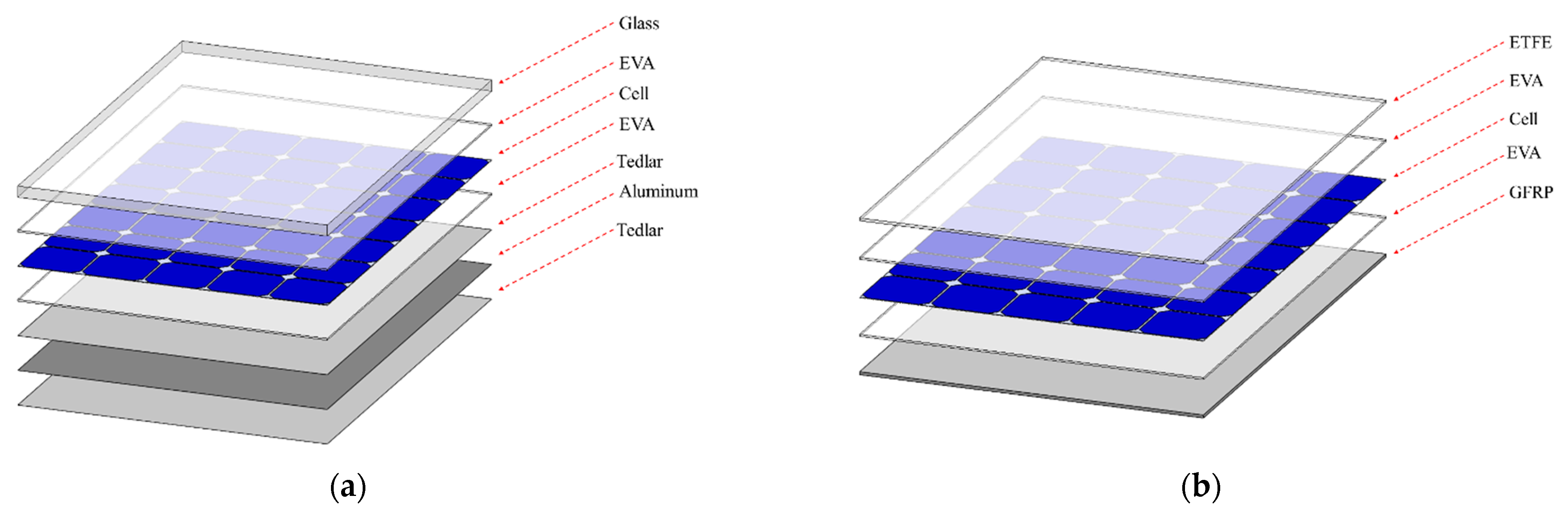
3.2.2. Type and Material

In recent years, along with the development of solar cell manufacturing technologies, various types of these cells have been launched on the market, each with specific advantages and limitations [6]. According to recent studies, the efficiency of solar cells based on III–V is higher than others. Furthermore, among these types of cells, the six-junction III–V cell has the highest efficiency [46]. Generally, each solar cell’s efficiency, advantages, and limitations are different, and depending on the conditions, they can be integrated into different parts of the vehicle body. Additionally, according to Equation (2), the effect of the type of solar cell on the efficiency and the percentage of photovoltaic coverage on the body’s surface directly affects the output power of the VIPV system. As discussed in the previous section, different parts of the car body have limitations and technical conditions and are exposed to direct sunlight. For this reason, various solutions have been proposed for integrating different photovoltaic cells with different efficiency and benefits. Since as much as the percentage of covering the car body with photovoltaic cells increases, the total output power increases because of the area in the formula. In the previous sections, the potential of different parts of the car for installing a solar cell and the effect of its geometry on the output of the cell was investigated. In the following, the types of photovoltaic cells that can be used to be integrated into different parts of the car body and the advantages and challenges of each one have been investigated.
Crystalline silicon solar cells, as the primary and essential member of the first generation of solar cells, have become the most widely used and consumed solar cells in the world for reasons such as high durability, good stability in different weather conditions, good efficiency, and low price [47]. According to these cases, silicon-based crystalline solar cells are one of the essential options for integration into vehicle bodies. On the one hand, it has good efficiency, and on the other hand, due to the mobility of vehicles, it has good stability for use under these conditions. Of course, it should also be noted that the relevant cell is not flexible. Therefore, in some cases, such as personal cars, it cannot be integrated directly due to the complexity of the geometry. For this reason, apart from direct integration, various solutions such as removing the glass (Figure 7b) [32], thinning the cell [48], miniaturizing and changing the cell arrangement [49], and using different materials to laminate the cell to install solar cells on the body of vehicles have been proposed [50].
In addition to the mentioned geometric limitations, some junctions in silicon-based solar cells are located on the surface of the modules. In addition to shading, this issue will occupy the existing physical space. Since the surface of the car body and the number of solar cells that can be installed on it is limited, it is possible to use Interdigitated Back Contact (IBC) cells as one of the configurations of Rear Contact Solar Cells. In this type of solar cell, all or part of these connections are moved to the back of the cell and the space occupied by the connections between the cells is reduced [51]. According to Equation (2), the output power increases due to the increase in the coverage area of the solar cell on the body.
Amorphous silicon solar cells, belonging to the silicon-based solar cell family, fall under the classification of thin-film solar cells. Additionally, other solar cell variants such as CIGS and CdTe also fall within this category. The reduced silicon amount in amorphous silicon solar cells has resulted in a decrease in their price when compared to crystalline cells. However, it should be acknowledged that the efficiency of amorphous silicon cells is comparatively lower than that of crystalline cells. Nonetheless, the flexible nature of amorphous silicon solar cells renders them highly suitable for integration into the body of vehicles [39]. Particularly, vehicles with less complex body geometries such as trucks [33,39] and buses [29] demonstrate significant potential for thin film solar cell integration.
According to Equation (3), in VIPV systems, factors such as vehicle body curvature, shading factors, vehicle movement, and not being in the best position concerning the sun, unlike fixed solar systems, lead to a reduction in the curvature correction factor, PV surface coverage and radiation will enter, which will eventually reduce the output power of the photovoltaic system. According to the mentioned cases, using cells with higher efficiency and increasing the value of the solar cell efficiency parameter in Equation (2) influences the amount of output power and moderates the effect of these cases to some extent. As mentioned, the highest efficiency of solar cells is related to multi-junction solar cells [52]. These cells can be used in different modes, even with a concentrator for integration into the body of vehicles [53]. Using a concentrator structure and lenses with different concentrations can be effective in the amount of incoming radiation and, ultimately, the output power of the system (Figure 8a) [49,54]. Since when direct solar radiation decreases, this structure will be able to absorb radiation from different directions and focus it on the solar cell. Moreover, using flexible materials in this structure can help integrate fragile solar cells because different parts of the concentrator structure can be produced from flexible materials so that fragile solar cells can be installed on the surface of the car body [55]. Of course, one of the challenges of using the concentrator structure is creating a space between the cells placed in it. One of the solutions to this challenge is to install high-efficiency cells in the center of the lenses (such as multi-junction cells) and fill the space between these cells with low-cost solar cells (such as conventional silicon cells) [56]. The schematic of the proposed design (Partial CPV module) can be seen in Figure 8b.
However, in some vehicles, such as personal cars, windows constitute a percentage of the body. Mentioned cells cannot be installed in these parts due to a lack of transparency issued, blocking the passage of light that, if installed, will obstruct the mentioned items. In addition to equipping this part with a solar cell, transparent photovoltaic (TPV) cells can increase the output power by increasing the surface of the body covering due to the passage of light [57]. For example, Golubev and Lunt simulated the integration of these types of cells in the windows or the whole body to the calculation of the driving distance with potential VIPV power (miles per year) for five different American cities by a Jeep Grand Cherokee car (Energy Efficiency 26 kWh per 100 miles) [58]. According to these calculations, when these cells were integrated into the entire vehicle body, this value was between 9450 and 13,420 miles per year. When these cells were integrated only into the car windows, the calculated value was between 3000 and 4280 miles per year. The importance of using different types of solar cells becomes clear when known that according to these calculations, if only silicon cells were used in the roof, this amount would be 2770 to 3700 miles per year [58].

3.2.3. Interconnections and Electrical Devices

Each solar module consists of connecting several solar cells. The type of connection of these cells to each other in each string or for each cell can be in series or parallel and using different numbers of bypass diodes. Mentioned items can differ depending on the need and the system’s expected final output. Furthermore, the number of bypass diodes required depends on variables, such as the amount of curvature of the module, the amount of shading, etc., because the results have shown that adding a bypass diode in curved modules (with a greater equivalent spherical radius) can moderate the effects of curvature on output results and cause increase output voltage [49]. For this reason, different numbers of bypass diodes can be used in different systems according to other system characteristics. For example, Macias et al. [59] calculated the amount of daily energy production in kilowatt hours for two different sizes of solar cells (in the first case, 176 solar cells, each with dimensions of 80 × 80 mm square, and in the second case, with 54 solar cells each with dimensions of 144 × 144 mm) square) and eight different configurations. The mentioned items were calculated in two situations without shading factors (clear sky) and applying geometric shading. Results showed that increasing the number of bypass diodes in flat solar cells will not necessarily improve the system’s performance [59]. Of course, it should be noted that a vehicle-integrated photovoltaic system can be considered a microgrid of different electrical devices and different parts [60,61,62]. Therefore, apart from the effect of the internal connections of the solar cell, the efficiency and type of architecture of all the components of this microgrid also affect the overall performance of this type of system [11,63].

3.2.4. Temperature and Cooling Effect

All electronic systems possess a defined and specific temperature range to ensure optimal functionality. Operating within this range is crucial, as deviating from it can disrupt or challenge the system’s performance, ultimately impacting its efficiency [64]. Consequently, it becomes imperative to consider the appropriate temperature range for electronic systems, including solar cells [65]. Each solar cell produced typically exhibits a specific coefficient, indicating the influence of temperature variation on the system’s performance per degree. This aspect is also pertinent to Vehicle-Integrated Photovoltaic (VIPV) systems [66]. Figure 9 illustrates the impact of elevated module temperature on the open circuit voltage of a VIPV system for two distinct vehicles. As depicted, an increase in module temperature leads to a decrease in the open circuit voltage value of the VIPV system. However, it is worth noting that VIPV systems possess an advantageous characteristic when compared to fixed photovoltaic systems: the presence of a convection current generated by the moving vehicle, which positively influences the cooling process and aids in temperature control of the VIPV system [67].

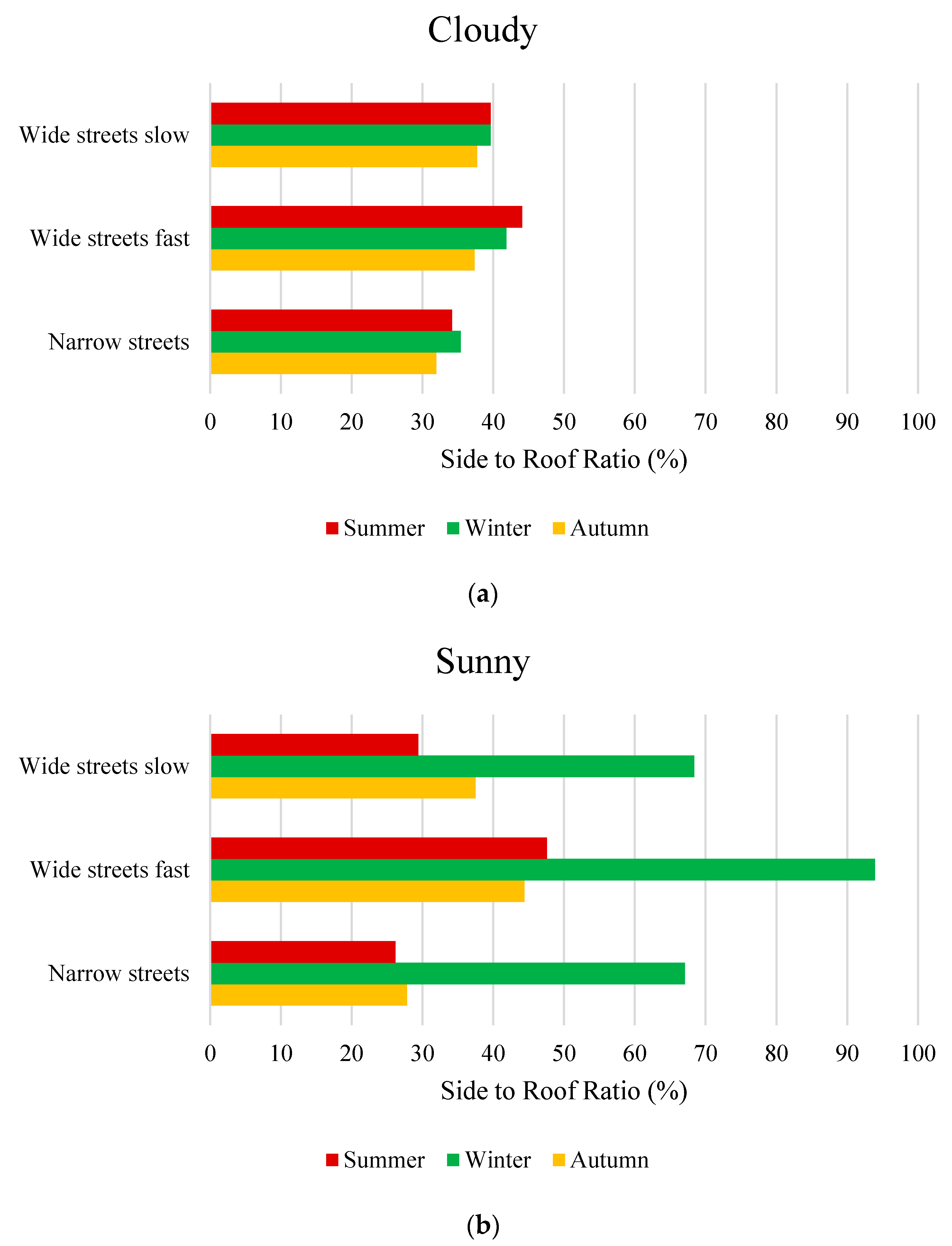
3.3. Environmental Conditions

So far, the influence of various factors, such as the type and geometry of the solar cell and its installation location, on the performance of an integrated photovoltaic system of vehicles has been studied. However, besides these things, for the proper design of a VIPV system, one should pay attention to variables such as climate, weather conditions, shading factors, etc. [68]. According to the mentioned conditions, the amount of incoming radiation and, as a result, the efficiency of the integrated photovoltaic system of vehicles will have different values [69]. For example, Golubev and Lunt [58] calculated the efficiency of a photovoltaic system integrated into the roof (the area of the roof of the car was 2.6 m2) of a Jeep Grand Cherokee. They simulated the integration of a typical silicone panel on the roof of this car for one day in Phoenix, Arizona. They first calculated efficiency according to the amount of daily radiation without considering the effect of the radiation angle and temperature, and, in the next step, they applied these effects respectively, which decreased efficiency from about 20% to about 16% [58].
As mentioned in the previous sections, the amount of incoming radiation differs for car parts, such as the roof and sides. However, the amount of this difference will vary according to different conditions. Among these things are the conditions of the driving route [70]. For example, in Figure 10, the ratio of the incoming radiation to the roof to the incoming radiation to the car’s sides can be seen for different conditions. The results of this graph are for a van on a 21 km route in Hanover, Germany (52°22′28″ N 9°44′19″ E). The mentioned route has been chosen to have the actual city driving conditions and different situations that can be experienced. The test route is divided into the following categories (in the first two cases, the average height of the buildings is 15 m with a standard deviation of 6.5):
  • Narrow streets with high building density with a speed limit of 30 km/h (the height of the building is greater than the distance between the vehicle and the building)
  • Wide, slow-moving streets such as alleys and streets with more than one lane in each direction, with a speed limit of 50 km/h (the height of the building is greater than the distance between the vehicle and the building)
  • Wide, fast streets with no adjacent buildings (but with several overpasses)
Of course, the assumed test path has been chosen so that for each category of mentioned cases, it exists equally in different directions of north–south (and vice versa) and west–east (and vice versa). The duration of each test varied between 40 and 55 min according to traffic and conditions. According to Figure 10, radiation is generally higher in sunny weather than in cloudy weather. Additionally, the radiation in cloudy weather has much to do with the season. Since the amount of radiation in winter is not much different in cloudy and sunny weather, in summer, the amount of radiation in sunny weather is about eight times that in cloudy weather [41].

4. Conclusions

In the present work, various factors affecting the performance of an integrated photovoltaic system of vehicles were investigated. These factors were studied in three general categories: installation position, solar cell, and environmental conditions. Each of the reviewed items is interdependent and cannot be separated. Since according to different conditions, the output of a VIPV system will be different. In general, the three main factors of photovoltaic cell coverage percentage on the body, the amount of incoming radiation, and photovoltaic cell efficiency should be considered to improve the performance of a VIPV system. For example, environmental factors such as atmospheric and climatic conditions, driving patterns, driving route conditions, and shading factors directly affect the amount of incoming radiation. In general, the amount of incoming radiation on the car roof is higher and requires the definition of lower standards for installing and integrating solar cells. However, due to the increase in the body’s surface covered with solar cells, other parts of the body were also considered. However, the amount of incoming radiation to these two areas differs in different conditions and significantly depends on environmental and atmospheric conditions. Since the Solar Altitude is lower in winter than in summer, the direct radiation to the roof is reduced. However, in cloudy conditions, the emission of light is higher and compensates for some of this decrease due to the increase of scattering in the atmosphere. Generally, the average radiation on the sides is about 43.1% of the average radiation on the roof. Of course, this value reaches about 92% in sunny winter and 26% in sunny summer conditions.
Each type of solar cell has advantages and challenges for integration into vehicle bodies. Therefore, the progress of various manufacturing technologies and the development of photovoltaic cells have led to the production of cells with higher efficiency. On the other hand, flexible and transparent solar cells can also help to increase the coverage of the car body with solar cells. Various other methods can help increase the body’s surface with a solar cell or its efficiency. Due to occupying some of the space in front of the cells by the internal connections, transferring them to the space behind the cells not exposed to the sun can improve the system’s performance (IBC solar cells). On the other hand, some solar cells may cause a challenge in the integration process due to their fragility, and variables such as miniaturizing the cells and, changing their arrangement, using different laminate methods for the polymer base layer and concentrator structure have been suggested. The use of the concentrator structure in cloudy weather conditions, when direct radiation is reduced, is also suitable for increasing the incoming radiation to the cells integrated into the roof of the car.

Author Contributions

Conceptualization, G.A. and F.V.; Methodology, P.R. and V.L.B.; Investigation, H.S.; Resources, F.V.; Data Curation, H.S.; Writing—Original Draft Preparation, H.S. and F.V.; Writing—Review & Editing, G.A., H.S. and F.V.; Visualization, P.R. and V.L.B.; Supervision, F.V.; Project Administration, G.A, P.R. and V.L.B. All authors have read and agreed to the published version of the manuscript.

Funding

This research received no external funding.

Data Availability Statement

Not applicable.

Conflicts of Interest

Not applicable.

References

  1. Yamaguchi, M.; Masuda, T.; Nakado, T.; Yamada, K.; Okumura, K.; Satou, A.; Ota, Y.; Araki, K.; Nishioka, K.; Kojima; et al. Analysis for Expansion of Driving Distance and CO2 Emission Reduction of Photovoltaic-Powered Vehicles. IEEE J. Photovolt. 2023, 13, 343–348. [Google Scholar] [CrossRef]
  2. Global Sales Statistics 2019–2021. 2021. Available online: https://www.oica.net/category/sales-statistics/ (accessed on 20 December 2022).
  3. CO2 Emissions from Transport Rebounded in 2021, Returning to Their Historical Growth Trend. 2021. Available online: https://www.iea.org/topics/transport (accessed on 22 December 2022).
  4. Ghosh, A. Possibilities and challenges for the inclusion of the electric vehicle (EV) to reduce the carbon footprint in the transport sector: A review. Energies 2020, 13, 2602. [Google Scholar] [CrossRef]
  5. Shrivastava, P.; Soon, T.; Mekhilef, S.; Ahmad, F. Economic and Environmental Analysis of a Solar-Powered EV Charging System in India—A Case Study. In Innovations in Electrical and Electronic Engineering: Proceedings of the ICEEE 2021, 17–19 December 2021, NCR New Delhi, India; Springer: Singapore, 2021; pp. 301–315. [Google Scholar]
  6. Yamaguchi, M.; Nakamura, K.; Ozaki, R.; Kojima, N.; Ohshita, Y.; Masuda, T.; Okumura, K.; Satou, A.; Nakado, T.; Yamada, K.; et al. Analysis for the Potential of High-Efficiency and Low-Cost Vehicle-Integrated Photovoltaics. Solar RRL 2022, 7, 2200556. [Google Scholar] [CrossRef]
  7. Kronthaler, L.; Maturi, L.; Moser, D.; Alberti, L. Vehicle-integrated Photovoltaic (VIPV) systems: Energy production, Diesel Equivalent, Payback Time; an assessment screening for trucks and busses. In Proceedings of the 2014 IEEE 9th International Conference on Ecological Vehicles and Renewable Energies (EVER), Monte-Carlo, Monaco, 25–27 March 2014; IEEE: New York, NY, USA, 2014. [Google Scholar]
  8. Manivannan, S.; Kaleeswaran, E. Solar powered electric vehicle. In Proceedings of the 2016 First International Conference on Sustainable Green Buildings and Communities (SGBC), Chennai, India, 18–20 December 2016; IEEE: New York, NY, USA, 2016. [Google Scholar]
  9. Ekins-Daukes, N.; Kay, M.; Ciesla, A.; Jiang, J.Y.; Yang, Z.; Perez-Wurfel, I.; Hopkins, R.; Mcdonald, J. The Potential for Vehicle Integrated Photovoltaics. In Proceedings of the Asia Pacific Solar Research Conference 2020 (APSRC), Merced, CA, USA, 30 November–2 December 2020; RMIT: Melbourne, Australia, 2020. [Google Scholar]
  10. Patel, N.; Bittkau, K.; Pieters, B.; Sovetkin, E.; Ding, K.; Reinders, A. Impact of Additional PV Weight on the Energy Consumption of Electric Vehicles with Onboard PV; IEEE: New York, NY, USA, 2023. [Google Scholar]
  11. Ben Said-Romdhane, M. and S. Skander-Mustapha, A Review on Vehicle-Integrated Photovoltaic Panels. Adv. Technol. Sol. Photovolt. Energy Syst. 2021, 349–370. [Google Scholar]
  12. Commault, B.; Duigou, T.; Maneval, V.; Gaume, J.; Chabuel, F.; Voroshazi, E. Overview and perspectives for vehicle-integrated photovoltaics. Appl. Sci. 2021, 11, 11598. [Google Scholar] [CrossRef]
  13. Brito, M.C.; Santos, T.; Moura, F.; Pera, D.; Rocha, J. Urban solar potential for vehicle integrated photovoltaics. Transp. Res. Part D Transp. Environ. 2021, 94, 102810. [Google Scholar] [CrossRef]
  14. Khan, S.; Sudhakar, K.; Yusof, M.H.B.; Azmi, W.H.; Ali, H.M. Roof integrated photovoltaic for electric vehicle charging towards net zero residential buildings in Australia. Energy Sustain. Dev. 2023, 73, 340–354. [Google Scholar] [CrossRef]
  15. Markert, J.; Kutter, C.; Newman, B.; Gebhardt, P.; Heinrich, M. Proposal for a Safety Qualification Program for Vehicle-Integrated PV Modules. Sustainability 2021, 13, 13341. [Google Scholar] [CrossRef]
  16. Filho, A.V.M.; Vasconcelos, A.S.; Junior, W.D.A.; Dantas, N.K.; Arcanjo, A.M.C.; Souza, A.C.; Fernandes, A.L.; Zhang, K.; Wu, K.; Castro, J.F.; et al. Impact Analysis and Energy Quality of Photovoltaic, Electric Vehicle and BESS Lead-Carbon Recharge Station in Brazil. Energies 2023, 16, 2397. [Google Scholar] [CrossRef]
  17. Ye, B.; Jiang, J.; Miao, L.; Yang, P.; Li, J.; Shen, B. Feasibility study of a solar-powered electric vehicle charging station model. Energies 2015, 8, 13265–13283. [Google Scholar] [CrossRef] [Green Version]
  18. Goli, P.; Shireen, W. PV powered smart charging station for PHEVs. Renew. Energy 2014, 66, 280–287. [Google Scholar] [CrossRef]
  19. Minh, P.V.; Le Quang, S.; Pham, M.-H. Technical economic analysis of photovoltaic-powered electric vehicle charging stations under different solar irradiation conditions in Vietnam. Sustainability 2021, 13, 3528. [Google Scholar] [CrossRef]
  20. Sovetkin, E.; Noll, J.; Patel, N.; Gerber, A.; Pieters, B.E. Vehicle-Integrated Photovoltaics Irradiation Modeling Using Aerial-Based LIDAR Data and Validation with Trip Measurements. Solar RRL 2022, 2200593. [Google Scholar] [CrossRef]
  21. Enescu, F.M.; Birleanu, F.G.; Raboaca, M.S.; Raceanu, M.; Bizon, N.; Thounthong, P. Electric Vehicle Charging Station Based on Photovoltaic Energy with or without the Support of a Fuel Cell–Electrolyzer Unit. Energies 2023, 16, 762. [Google Scholar] [CrossRef]
  22. Esfandyari, A.; Norton, B.; Conlon, M.; McCormack, S.J. Performance of a campus photovoltaic electric vehicle charging station in a temperate climate. Solar Energy 2019, 177, 762–771. [Google Scholar] [CrossRef]
  23. Cheikh-Mohamad, S.; Sechilariu, M.; Locment, F.; Krim, Y. Pv-powered electric vehicle charging stations: Preliminary requirements and feasibility conditions. Appl. Sci. 2021, 11, 1770. [Google Scholar] [CrossRef]
  24. Karoui, F.; Claudon, F.; Chambion, B.; Catellani, S.; Commault, B. Estimation of integrated photovoltaics potential for solar city bus in different climate conditions in Europe. J. Phys. Conf. Ser. 2023, 2454, 012007. [Google Scholar] [CrossRef]
  25. Ford C-Max Solar Energi: La Première Vraie Voiture Solaire? 2014. Available online: https://www.lepoint.fr/automobile/innovations/ford-c-max-solar-energi-la-premiere-vraie-voiture-solaire-03-01-2014-1776499_652.php#11 (accessed on 13 March 2023).
  26. Leutenegger, S.; Jabas, M.; Siegwart, R.Y. Solar airplane conceptual design and performance estimation: What size to choose and what endurance to expect. J. Intell. Robot. Syst. 2011, 61, 545–561. [Google Scholar] [CrossRef]
  27. Oh, M.; Kim, S.-M.; Park, H.-D. Estimation of photovoltaic potential of solar bus in an urban area: Case study in Gwanak, Seoul, Korea. Renew. Energy 2020, 160, 1335–1348. [Google Scholar] [CrossRef]
  28. Flixbus Fleet Tests 18% CIGS Panels. 2020. Available online: https://www.pv-magazine.com/2020/02/11/flixbus-fleet-tests-18-cigs-panels/ (accessed on 6 February 2023).
  29. Spagnolo, G.S.; Papalillo, D.; Martocchia, A.; Makary, G. Solar-electric boat. J. Transp. Technol. 2012, 2, 144–149. [Google Scholar] [CrossRef] [Green Version]
  30. Kim, H.; Ku, J.; Kim, S.M.; Park, H.D. A new GIS-based algorithm to estimate photovoltaic potential of solar train: Case study in Gyeongbu line, Korea. Renew. Energy 2022, 190, 713–729. [Google Scholar] [CrossRef]
  31. Solar Powered Trucks. 2020. Available online: https://tsscgroup.com/products-and-services/truck-bodies-semi-trailers/solar-powered-trucks/ (accessed on 31 January 2023).
  32. Kutter, C.; Basler, F.; Alanis, L.E.; Markert, J.; Heinrich, M.; Neuhaus, D.H. Integrated lightweight, glass-free PV module technology for box bodies of commercial trucks. In Proceedings of the 37th European PV Solar Energy Conference and Exhibition, Online, 7–11 September 2020. [Google Scholar]
  33. Flexible PV Fabric for Heavy Transport. 2021. Available online: https://www.pv-magazine.com/2021/06/02/flexible-pv-fabric-for-heavy-transport/ (accessed on 31 January 2023).
  34. ‘Solar Power Truck’ Dispatched to Area Affected by Great East Japan Earthquake. 2011. Available online: https://www.japanfs.org/en/news/archives/news_id030963.html (accessed on 6 February 2023).
  35. Sagaria, S.; Duarte, G.; Neves, D.; Baptista, P. Photovoltaic integrated electric vehicles: Assessment of synergies between solar energy, vehicle types and usage patterns. J. Clean. Prod. 2022, 348, 131402. [Google Scholar] [CrossRef]
  36. Pavlovic, A.; Sintoni, D.; Fragassa, C.; Minak, G. Multi-objective design optimization of the reinforced composite roof in a solar vehicle. Appl. Sci. 2020, 10, 2665. [Google Scholar] [CrossRef]
  37. Lee, K.Y.; Park, S. Reducing Charging Burden of Light Electric Vehicles by Integrated Photovoltaic Modules. In Proceedings of the 2022 IEEE Vehicle Power and Propulsion Conference (VPPC), Merced, CA, USA, 1–4 November 2022; IEEE: New York, NY, USA, 2022. [Google Scholar]
  38. Sion—Infinite mobility. 2018. Available online: https://sonomotors.com/sion.html/ (accessed on 8 January 2023).
  39. Peibst, R.; Fischer, H.; Brunner, M.; Schießl, A.; Wöhe, S.; Wecker, R.; Haase, F.; Schulte-Huxel, H.; Blankemeyer, S.; Köntges, M.; et al. Demonstration of Feeding Vehicle-Integrated Photovoltaic-Converted Energy into the High-Voltage On-Board Network of Practical Light Commercial Vehicles for Range Extension. Solar RRL 2022, 6, 2100516. [Google Scholar] [CrossRef]
  40. Araki, K.; Ota, Y.; Yamaguchi, M. Measurement and modeling of 3D solar irradiance for vehicle-integrated photovoltaic. Appl. Sci. 2020, 10, 872. [Google Scholar] [CrossRef] [Green Version]
  41. Wetzel, G.; Salomon, L.; Krügener, J.; Bredemeier, D.; Peibst, R. High time resolution measurement of solar irradiance onto driving car body for vehicle integrated photovoltaics. Prog. Photovolt. Res. Appl. 2022, 30, 543–551. [Google Scholar] [CrossRef]
  42. Ota, Y.; Masuda, T.; Araki, K.; Yamaguchi, M. Curve-correction factor for characterization of the output of a three-dimensional curved photovoltaic module on a car roof. Coatings 2018, 8, 432. [Google Scholar] [CrossRef] [Green Version]
  43. Ota, Y.; Araki, K.; Nagaoka, A.; Nishioka, K. Facilitating vehicle-integrated photovoltaics by considering the radius of curvature of the roof surface for solar cell coverage. Clean. Eng. Technol. 2022, 7, 100446. [Google Scholar] [CrossRef]
  44. Araki, K.; Ota, Y.; Lee, K.H.; Yamada, N.; Yamaguchi, M. Curve correction of the energy yield by flexible photovoltaics for VIPV and BIPV applications using a simple correction factor. In Proceedings of the 2019 IEEE 46th Photovoltaic Specialists Conference (PVSC), Chicago, IL, USA, 16–21 June 2019; IEEE: New York, NY, USA, 2019. [Google Scholar]
  45. Tayagaki, T.; Araki, K.; Yamaguchi, M.; Sugaya, T. Impact of nonplanar panels on photovoltaic power generation in the case of vehicles. IEEE J. Photovolt. 2019, 9, 1721–1726. [Google Scholar] [CrossRef]
  46. Tayagaki, T.; Araki, K.; Yamaguchi, M.; Sugaya, T. Development of high-efficiency and low-cost solar cells for PV-powered vehicles application. Prog. Photovolt. Res. Appl. 2021, 29, 684–693. [Google Scholar]
  47. Hosseini, S.M.J.; Samadi, H. Solar Energy and Applications; Golestan University: Gorgan, Iran, 2022. [Google Scholar]
  48. Kim, S.; Holz, M.; Park, S.; Yoon, Y.; Cho, E.; Yi, J. Future options for lightweight photovoltaic modules in electrical passenger cars. Sustainability 2021, 13, 2532. [Google Scholar] [CrossRef]
  49. Yamada, N. Vehicle-integrated 3D-PV module with III-V and Si solar cells. In Proceedings of the 2020 47th IEEE Photovoltaic Specialists Conference (PVSC), Calgary, AB, Canada, 15 June–21 August 2020. [Google Scholar]
  50. Duigou, T.; Boichon, V.; Brancaz, X.; Chabuel, F.; Francescato, P.; Gaume, J.; Habchi, G.; Lagache, M.; Saffré, P.; Tenchine, L. VIPV: Process development of integrated photovoltaic cells in a double-curved composite structure for automotive application. In Proceedings of the 37th European Photovoltaic Solar Energy Conference and Exhibition, Online, 7–11 September 2020.
  51. Stein, J.; Reise, C.; Castro, J.B.; Friesen, G.; Maugeri, G.; Urrejola, E.; Ranta, S. Bifacial Photovoltaic Modules and Systems: Experience and Results from International Research and Pilot Applications; Sandia National Lab (SNL-NM): Albuquerque, NM, USA; Fraunhofer: Munich, Germany, 2021. [Google Scholar]
  52. Yamaguchi, M.; Lee, K.H.; Sato, D.; Araki, K.; Kojima, N.; Takamoto, T.; Masuda, T.; Satou, A. Overview of Si tandem solar cells and approaches to PV-powered vehicle applications. MRS Adv. 2020, 5, 441–450. [Google Scholar] [CrossRef]
  53. Sato, D.; Lee, K.H.; Araki, K.; Masuda, T.; Yamaguchi, M.; Yamada, N. Design and Evaluation of Low-concentration Static III-V/Si Partial CPV Module for Car-rooftop Application. In Proceedings of the 2018 IEEE 7th World Conference on Photovoltaic Energy Conversion (WCPEC) (A Joint Conference of 45th IEEE PVSC, 28th PVSEC & 34th EU PVSEC), Waikoloa, HI, USA, 10–15 June 2018; IEEE: New York, NY, USA, 2018. [Google Scholar]
  54. Sato, D.; Masuda, T.; Tomizawa, R.; Yamada, N. Theoretical concentration limit and maximum annual optical efficiency of static/low-concentration CPV for horizontal integration to vehicle bodies. Opt. Express 2022, 30, 846–863. [Google Scholar] [CrossRef] [PubMed]
  55. Araki, K.; Ji, L.; Kelly, G.; Ham, A.V.D.; Agudo, E.; Antón, I.; Baudrit, M.; Carr, A.; Herrero, R.; Kurtz, S.; et al. How did the knowledge of CPV contribute to the standardization activity of VIPV? In AIP Conference Proceedings; AIP Publishing LLC: Melville, NY, USA, 2020. [Google Scholar]
  56. Sato, D.; Lee, K.H.; Araki, K.; Masuda, T.; Yamaguchi, M.; Yamada, N. Design of low-concentration static III-V/Si partial CPV module with 27.3% annual efficiency for car-roof application. Prog. Photovolt. Res. Appl. 2019, 27, 501–510. [Google Scholar] [CrossRef]
  57. Nukunudompanich, M.; Sriprapai, D.; Sontikaew, S. Aspects of optical and thermal performances in flexible perovskite solar cells made of nanomaterials with potential for development of vehicle-integrated photovoltaics. Mater. Today Proc. 2022, 66, 3163–3167. [Google Scholar] [CrossRef]
  58. Golubev, T.; Lunt, R.R. Evaluating the Electricity Production of Electric Vehicle-Integrated Photovoltaics via a Coupled Modeling Approach. In Proceedings of the 2021 IEEE 48th Photovoltaic Specialists Conference (PVSC), Online, 20–25 June 2021; IEEE: New York, NY, USA, 2021. [Google Scholar]
  59. Macías, J.; Herrero, R.; Núñez, R.; Antón, I. On the effect of cell interconnection in Vehicle Integrated Photovoltaics: Modelling energy under different scenarios. In Proceedings of the 2021 IEEE 48th Photovoltaic Specialists Conference (PVSC), Online, 20–25 June 2021; IEEE: New York, NY, USA, 2021. [Google Scholar]
  60. Ashique, R.H.; Salam, Z.; Aziz, M.J.B.A.; Bhatti, A.R. Integrated photovoltaic-grid dc fast charging system for electric vehicle: A review of the architecture and control. Renew. Sustain. Energy Rev. 2017, 69, 1243–1257. [Google Scholar] [CrossRef]
  61. AbuElrub, A.; Hamed, F.; Saadeh, O. Microgrid integrated electric vehicle charging algorithm with photovoltaic generation. J. Energy Storage 2020, 32, 101858. [Google Scholar] [CrossRef]
  62. Van Der Kam, M.; van Sark, W. Smart charging of electric vehicles with photovoltaic power and vehicle-to-grid technology in a microgrid; a case study. Appl. Energy 2015, 152, 20–30. [Google Scholar] [CrossRef] [Green Version]
  63. Carr, A.J.; van den Tillaart, E.; Burgers, A.R.; Köhler, T.; Newman, B.K. Vehicle integrated photovoltaics: Evaluation of the energy yield potential through monitoring and modelling. In Proceedings of the 37th EUPVSEC European PV Solar Energy Conference and Exhibition, Lisbon, Portugal, 7–11 September 2020; WIP GmbH & Co Planungs-KG: Munich, Germany, 2020. [Google Scholar]
  64. Samadi, H.; Hosseini, M.J.; Ranjbar, A.A.; Pahamli, Y. Thermohydraulic performance of new minichannel heat sink with grooved barriers. Int. Commun. Heat Mass Transf. 2023, 144, 106753. [Google Scholar] [CrossRef]
  65. Yamaguchi, M.; Masuda, T.; Araki, K.; Ota, Y.; Nishioka, K.; Takamoto, T.; Thiel, C.; Tsakalidis, A.; Jaeger-Waldau, A.; Okumura, K.; et al. Analysis of temperature coefficients and their effect on efficiency of solar cell modules for photovoltaics-powered vehicles. J. Phys. D Appl. Phys. 2021, 54, 504002. [Google Scholar] [CrossRef]
  66. Tiano, F.A.; Rizzo, G.; Marino, M.; Monetti, A. Evaluation of the potential of solar photovoltaic panels installed on vehicle body including temperature effect on efficiency. ETransportation 2020, 5, 100067. [Google Scholar] [CrossRef]
  67. Hayakawa, Y.; Sato, D.; Yamada, N. Measurement of the Convective Heat Transfer Coefficient and Temperature of Vehicle-Integrated Photovoltaic Modules. Energies 2022, 15, 4818. [Google Scholar] [CrossRef]
  68. Park, C.; Park, H.; Jeon, H.; Choi, K.; Suh, J. Evaluation and Validation of Photovoltaic Potential Based on Time and Pathway of Solar-Powered Electric Vehicle. Appl. Sci. 2023, 13, 1025. [Google Scholar] [CrossRef]
  69. Araki, K.; Ota, Y.; Nishioka, K.; Tobita, H.; Ji, L.; Kelly, G.; Yamaguchi, M. Toward the Standardization of the Car-roof PV–The challenge to the 3-D Sunshine Modeling and Rating of the 3-D Continuously Curved PV Panel. In Proceedings of the 2018 IEEE 7th World Conference on Photovoltaic Energy Conversion (WCPEC) (A Joint Conference of 45th IEEE PVSC, 28th PVSEC & 34th EU PVSEC), Waikoloa, HI, USA, 10–15 June 2018; IEEE: New York, NY, USA, 2018. [Google Scholar]
  70. Ng, C.W.; Zhang, J.; Tay, S.E. A tropical case study quantifying solar irradiance collected on a car roof for vehicle integrated photovoltaics towards low-carbon cities. In Proceedings of the 2020 47th IEEE Photovoltaic Specialists Conference (PVSC), Calgary, AB, Canada, 15 June–21 August 2020; IEEE: New York, NY, USA, 2020. [Google Scholar]
Figure 1. The number of annually published papers in 2011–2023 on VIPVs.
Wevj 14 00154 g001
Figure 2. Correlation between journals in the last years on the topic of vehicles integrated photovoltaic.
Wevj 14 00154 g002
Figure 3. (a) Integrated solar cells and (b) Solar range of Sion per week [38].
Wevj 14 00154 g003aWevj 14 00154 g003b
Figure 4. Schematic of pyranometers installed on the car and the results obtained from them for an experiment in (a) Hanover, Germany [39] (b) Miyazaki, Japan [42].
Wevj 14 00154 g004
Figure 5. (a) Schematic of projected surface (blue part) and curved surface (gray part) [40] and (b) calculated values for four different surfaces [44].
Wevj 14 00154 g005
Figure 6. Schematic of a commercial vehicle and dimensionless parameters defined to describe its roof [43].
Wevj 14 00154 g006
Figure 7. Structure of a solar cell crystalline silicon (a) Conventional (b) Lightweight [32].
Wevj 14 00154 g007
Figure 8. Schematic of the use of concentrator structure in solar cells (a) normal state (b) proposed structure (Partial CPV module) [56].
Wevj 14 00154 g008
Figure 9. Effect of increasing the temperature of the solar module installed on two different cars on the open circuit voltage [67].
Wevj 14 00154 g009
Figure 10. Ratio of irradiance to roof of the car compared to sides (%) in different conditions and in (a) cloudy (b) sunny weather [41].
Wevj 14 00154 g010
Table 1. Eight dimensionless parameters defined to describe the roof of different commercial vehicles [43].
ParameterDetails
m x Order of the curve of the ridgeline in the width direction
m y 1 Order of the curve of the front ridge of the side
m y 2 Order of the curve of the ridgeline behind the side
θ x Tangential angle in the width direction
θ y 1 Forward tangential angle
θ y 2 Backward tangential angle
r 1 Relative distance from the top of the vehicle roof to the front end
r 2 Relative distance from the top of the vehicle roof to the rear end
Disclaimer/Publisher’s Note: The statements, opinions and data contained in all publications are solely those of the individual author(s) and contributor(s) and not of MDPI and/or the editor(s). MDPI and/or the editor(s) disclaim responsibility for any injury to people or property resulting from any ideas, methods, instructions or products referred to in the content.

