Article

Slip Ratio Adaptive Control Based on Wheel Angular Velocity for Distributed Drive Electric Vehicles

School of Mechanical and Electrical Engineering, Jiangxi University of Science and Technology, Ganzhou 341000, China
*
Author to whom correspondence should be addressed.
World Electr. Veh. J. 2023, 14(5), 119; https://doi.org/10.3390/wevj14050119
Submission received: 8 March 2023 / Revised: 24 April 2023 / Accepted: 25 April 2023 / Published: 1 May 2023
(This article belongs to the Special Issue Advanced Vehicle System Dynamics and Control)

Abstract

:
In order to solve the adaptability problem of acceleration slip regulation for distributed drive electric vehicles, a slip ratio adaptive control strategy based on wheel angular velocity is proposed. The principle of road estimation algorithm based on the Burckhardt tire model is analyzed, and an improved estimation principle for optimal slip ratio is designed to improve the speed and accuracy of optimal slip ratio estimation. A slip ratio control strategy based on a conditional integral sliding mode control is designed, and its stability is proven. To make the slip ratio control strategy have better practicability, the slip ratio control strategy is combined with the road estimation algorithm, and the control variable of the slip ratio adaptive control strategy based on a conditional integral sliding mode control is redesigned to obtain a faster vehicle dynamic response. Finally, the effectiveness of the designed road estimation algorithm and the slip ratio adaptive control strategy is verified by simulation of acceleration on joint road and split road. Results show that the designed road estimator can obtain the road adhesion coefficient and optimal slip ratio quickly and accurately; the slip ratio adaptive controller, based on a conditional integral sliding mode control, can maintain the wheel slip ratio near the optimal slip ratio and reduce the steady-state error of the wheel slip ratio.

1. Introduction

The distributed drive electric vehicle is one in which the driving force and braking force of each wheel can be controlled independently, and the functions of anti-lock braking, traction control, and electronic stability control can be easily realized through its motor control technology [1]. Wheel slip control is the basis for vehicle stability control [2], and the optimal slip ratio of a driving wheel will change with the road conditions. The aim of slip ratio control for a distributed drive electric vehicle is to keep the slip ratio of wheels at the optimal slip ratio. Therefore, to achieve optimal wheel slip ratio control, two main problems need to be solved. The first problem is how to accurately obtain the optimal wheel slip ratio according to the vehicle driving conditions, and the second problem is how to keep the wheel slip ratio maintaining optimal value under the driving conditions.
In order to realize adaptive control of the wheel slip ratio, it is necessary to estimate the adhesion coefficient and optimal slip ratio of the driving road. The design of a road estimator is generally based on the vehicle dynamics and sensor signals. With the development of road estimation algorithms, more and more road estimators use both vehicle dynamic response and external sensor signals. For example, the normalized Dugoff tire model and the 7-DOF vehicle model have been built, and the road adhesion coefficient observer, based on the unscented Kalman filter algorithm, normalized Dugoff tire model, and 7-DOF vehicle model, has been established [3]. In order to improve the speed and accuracy of the road adhesion coefficient estimation, the fusion strategy of combining a dynamic estimator and visual estimator is designed. The dynamic estimator is designed based on the modified Burckhardt tire model, and the visual estimator is designed based on a vehicle-mounted camera [4]. A dynamic joint estimation method of side slip angle and road adhesion coefficient based on an inertial measurement unit and built-in speed/angle sensor is proposed. Previously, the side slip angle estimator was established based on vehicle dynamics and the Dugoff tire model; the road adhesion coefficient estimator was established based on machine learning and double radial basis neural network; and the extended Kalman filter method was used to estimate the side slip angle and road adhesion coefficient. However, judging from the simulation results, the estimated road adhesion coefficient fluctuates greatly [5].
Previously, a self-adaptation acceleration slip regulation controller based on a double fuzzy algorithm was designed, and the acceleration slip regulation algorithm for the front and rear axle was designed separately, but the design of fuzzy rules relies on expert knowledge [6]. A Fuzzy-PID controller that takes the optimal slip ratio as the control target was also designed, and a road estimation method was proposed, which uses the angular acceleration error as the basis for estimating the road conditions, but its accuracy needs to be further improved [7]. An optimal slip ratio estimator based on the wheel’s angular acceleration and the motor torque was designed, and a fuzzy control method is proposed to control the slip ratio of the wheels. However, the estimation accuracy of the optimal slip ratio of the changing road needs to be improved [8]. A longitudinal slip ratio control technique based on a sliding mode control was proposed, but the wheel slip ratio adaptive control cannot be realized when the vehicle is driving on variable roads [9]. A robust wheel slip ratio control system based on a sliding mode control was proposed; simulations and experiments were carried out to validate the effectiveness of the proposed algorithms, but the proposed control method could not maintain the wheel slip ratio close to the optimal slip ratio [10]. Two methods of estimation of tire road friction based on the extended Kalman filter and wheel speed measurements were designed and combined with the sliding mode traction controller, but the accuracy of the estimated road friction coefficient and the control effects needed to be further improved [11]. The road condition recognition method based on a non-standard method is designed to estimate the optimal slip rate of the road. An improved adaptive sliding mode controller, in which the sliding mode surface and reaching law are redesigned, is designed to optimize the control accuracy and vibration problems of the sliding mode control. However, adding integral control to the sliding surface may cause an integral saturation problem [12]. An acceleration slip regulation control strategy based on a variable gain controller was proposed, and the co-simulation of MATLAB/Simulink and Carsim was carried out to verify the effectiveness of the designed control strategy [13]. A novel fuzzy sliding mode control scheme is proposed to obtain the best battery condition and energy recovery efficiency; the fuzzy logic controller is designed to adjust the sliding mode parameters according to slip ratio, and a torque distribution strategy is proposed to best allocate the pneumatic and motor braking torque [14]. The effect of tire and soil parameters on the vehicle is investigated, and the experiment is carried out to analyze the effect of soil strength and tire parameters on the wheel mobility number. The result shows that the proposed wheel mobility number is the square root of the ratio between the tire loaded height and the tire diameter under the same loading conditions. Therefore, the influence of tire parameters on wheel dynamic response should be taken into account in the future study of wheel slip ratio control [15].
In order to solve the problems of the chattering phenomenon and the steady-state error of wheel slip ratio sliding mode control (SMC) for the distributed drive electric vehicle, a sliding mode control method based on a conditional integral sliding mode control (CISMC) is herein proposed, and the road estimation algorithm is designed based on the Burckhardt tire model. The motor torque is controlled according to the estimated optimal slip ratio, and the simulation of acceleration on joint road and split road is carried out. This paper is divided into five sections. The introduction is given in Section 1. Section 2 aims to establish the road estimator to estimate the adhesion coefficient of the driving road and the optimal wheel slip ratio. Section 3 aims to design the slip ratio adaptive control strategy to make the wheel slip ratio change with the road conditions and maintain the wheel slip ratio at an optimal value. Section 4 aims to verify the effectiveness and performance of the designed road estimator and slip ratio adaptive controller. Section 5 is the conclusions. The main framework of the paper is shown in Figure 1.

2. Design of the Road Estimation Algorithm

In the actual driving process of the vehicle, the road adhesion coefficient and the optimal slip ratio of the four wheels often change. The power, economy, and safety of the vehicle will not be guaranteed if the wheel driving force cannot be adjusted according to road conditions to keep the wheel slip ratio at the optimal state. Therefore, it is necessary to design a road estimation algorithm to obtain the road adhesion coefficient in real time and accurately.

2.1. Establishment of the Tire Model

The Burckhardt tire model can describe the relationship between adhesion coefficients and slip ratio through fewer parameters [16], so the Burckhardt tire model is used to design the road estimation algorithm. The tire model expression is as follows:
μ s t i λ = C 1 1 e C 2 λ C 3 λ
where C 1 is the maximum value of the μ λ curve; C 2 is the longitudinal stiffness; C 3 is the parameter of μ λ curve falling section.
The C 1 , C 2 , C 3 of different roads are shown in Table 1.

2.2. Estimation of Optimal Slip Ratio

The optimal slip ratio is the slip ratio when the road adhesion coefficient reaches the maximum, which is the slip ratio corresponding to the derivative of the road adhesion coefficient of the road at 0 [18]. The derivation of the Burckhardt tire model is obtained by Equation (2).
d μ d λ = C 1 C 2 e C 2 λ C 3
When d μ d λ = 0 , the optimal slip ratio and peak road adhesion coefficient are obtained by Equation (3).
λ o p t = 1 C 2 ln C 1 C 2 C 3 μ max = C 1 C 3 C 2 ( 1 + ln C 1 C 2 C 3 )
In order to obtain the optimal slip ratio and peak road adhesion coefficient, it is necessary to estimate the values of C 1 , C 2 , C 3 .
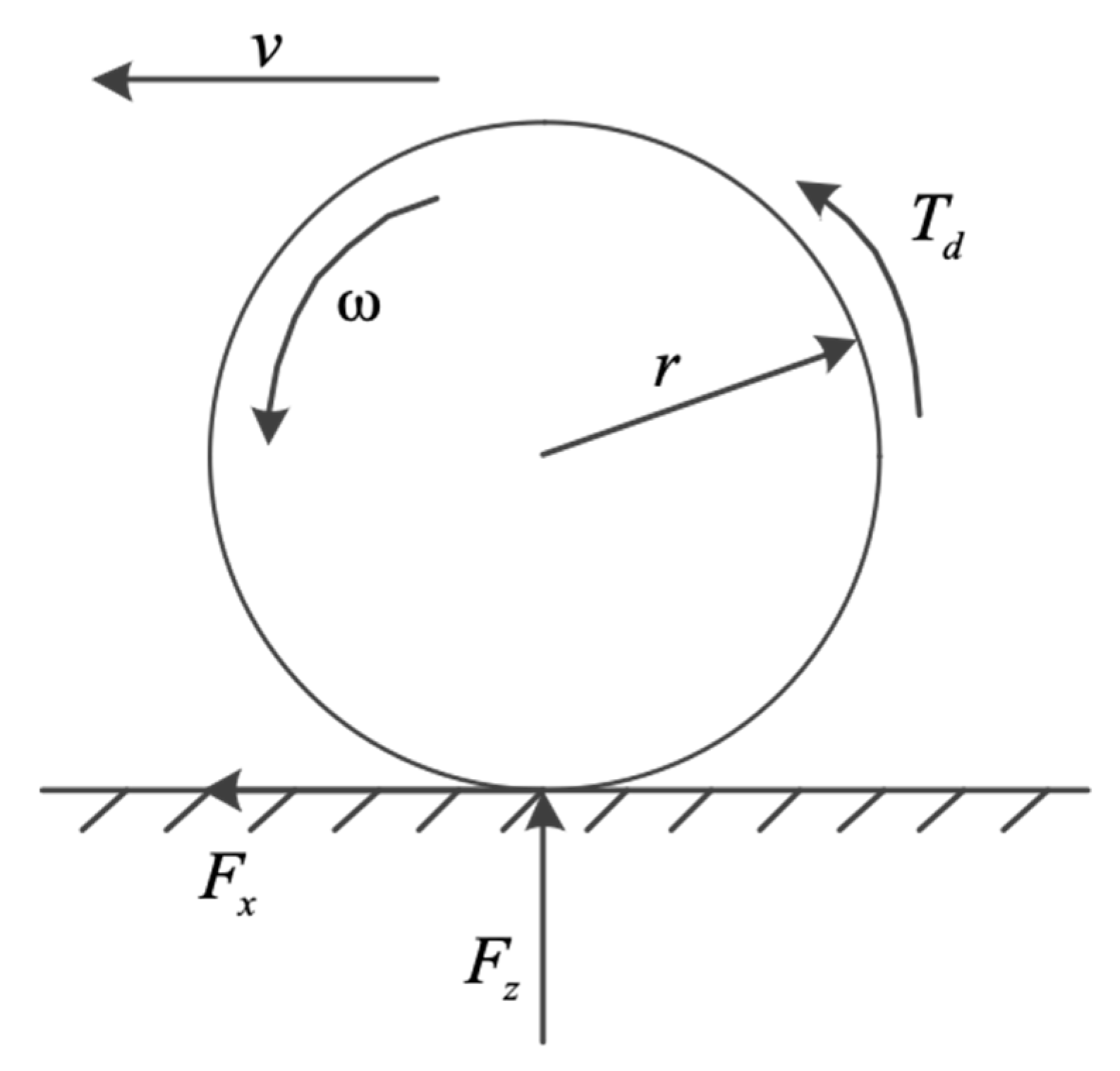
As an important part of the vehicle dynamics model, the wheel model mainly includes the torque balance equation and the vertical load to describe wheel motion [19]. A single wheel model is shown in Figure 2.
The balance equation for wheel torque during driving is as follows;
I w ω ˙ = T d F x r
m v ˙ = F x f l o s s
F x = F z μ λ
λ = ω r v v
where, I w is the moment of inertia of wheel, ω ˙ is the wheel angular acceleration, T d is the motor driving torque, r is the wheel rolling radius, F x is the longitudinal force of wheel, m is the equivalent mass coupled to the wheel, f l o s s contains the aerodynamic drag, rolling resistance, and grading resistance terms [20], μ λ is the utilization adhesion coefficient, v is the vehicle speed, F z is the ground normal force.
The main principle of road estimation is comparing the utilization adhesion coefficient with the adhesion coefficient of each standard roads under the current slip ratio to determine the similarity of the driving road to each standard roads, then the peak adhesion coefficient of the driving road is obtained by combining the peak adhesion coefficients of eight standard roads.
In order to obtain the road adhesion coefficient of driving road and the optimal wheel slip ratio of, following assumptions are made. First, vehicle speed, wheel angular velocity and ground normal force can be obtained through corresponding sensor. Second the peak adhesion coefficient of driving road is obtained by combining the peak adhesion coefficients of eight standard roads.
The utilization adhesion coefficient is calculated and compared with the road adhesion coefficient of the standard roads. So as to determine the type of current driving road, the utilization adhesion coefficient is calculated by Equation (8) [21].
μ u l λ = F x F z = T d I w ω ˙ r F z
The weight coefficient between driving road and each standard roads is calculated by Equation (9).
w i = 1 μ s t i λ μ u l λ + e p s
where, μ s t i λ is the road adhesion coefficient of each standard roads under the wheel slip ratio λ , and e p s is the infinitesimal.
The weight coefficient representation the similarity of the utilization adhesion coefficient to the road adhesion coefficient of standard roads under current wheel slip ratio. According to the weight coefficient, the peak adhesion coefficient and the optimal slip ratio of the driving road are calculated by Equation (10).
μ max i j = w i μ s t i max w i λ o p t i j = w i λ s t i o p t w i
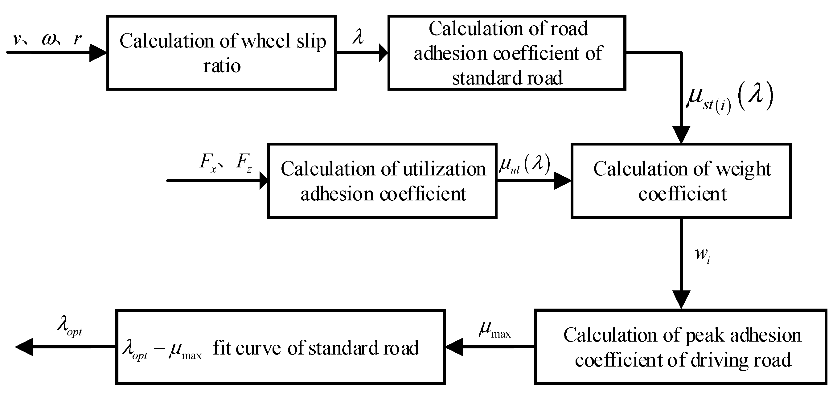
Although the Equation (10) can accurately obtain the optimal slip ratio of the road, but exist steady-state error, which will have a bad impact on the control effect of the slip ratio controller. In view of the above problem, the optimal slip ratio estimation method is redesigned, and the improved estimation principle of optimal slip ratio is shown in Figure 3.
As Figure 3 shows, the wheel slip ratio is calculated by Equation (7); the road adhesion coefficient of the standard road μ s t i λ is calculated by Equation (1); and the weight coefficient w i is calculated by the road adhesion coefficient of each standard road μ s t i λ and the utilization adhesion coefficient μ u l λ based on Equation (8). The peak road adhesion coefficient μ max is obtained by the weight coefficient w i based on Equation (10), then the optimal slip ratio λ o p t is obtained based on the λ o p t μ max fit curve of standard roads.
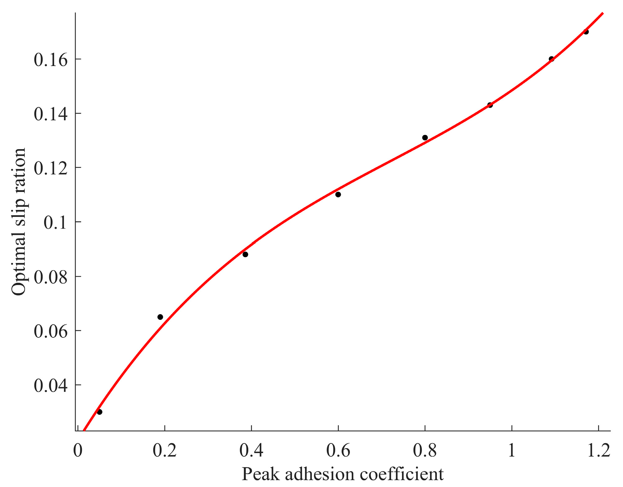
The λ o p t μ max curve of standard roads is shown in Figure 4. As shown in Figure 4, the relationship between peak adhesion coefficient and optimal slip ratio can be described by mathematical expression.
In order to better describe the relationship between λ o p t and μ max , the relationship curve of the optimal slip ratio and the peak adhesion coefficient of eight standard roads are fitted by MATLAB, as shown in Figure 5.
The optimal slip ratio expression is determined by Equation (11).
λ o p t μ max = p 1 μ max 3 + p 2 μ max 2 + p 3 μ max + p 4
where p 1 , p 2 , p 3 , and p 4 are the fitting parameters of the optimal slip ratio–peak adhesion coefficient curve.
As shown in Figure 5, the fitting curve of the optimal slip ratio–peak adhesion coefficient almost coincides with that of each standard road surface, and the fitting determination coefficient is 0.998. Therefore, Equation (11) can accurately describe the relationship between optimal slip ratio and peak adhesion coefficient.
When the peak adhesion coefficient of the current driving road is estimated, the optimal slip ratio of the driving road can be estimated accurately.
The road estimation Algorithm 1 is as follows:
Algorithm 1 Road estimation algorithm
Input:  v , ω , T d , F z
Initialize:  v 0 = 0 , ω 0 = 0 , T d 0 = 0 , F z 0 = 0 , μ max 0 = 0 , λ o p t 0 = 0
For  t = 0 : 0.001 : 10  do
λ = ω r v v , μ u l λ = T d I w ω ˙ r F z , μ s t i λ = C 1 1 e C 2 λ C 3 λ , w i = 1 μ s t i λ μ u l λ + e p s ,
μ max = w i μ s t i max w i
If  0 < μ max < 0.325 , then
μ max = 0.1 * r o u n d μ max * 3
Elseif 0.325 < μ max < 0.4
μ max = 0.1 * r o u n d μ max * 5
Elseif 0.4 < μ max < 0.6
μ max = 0.1 * r o u n d μ max * 10 / 1.4
Elseif 0.6 < μ max < 0.681
μ max = 0.1 * r o u n d μ max * 10 / 1.3
Elseif 0.681 < μ max < 0.74
μ max = 0.1 * r o u n d μ max * 10 / 1.2
Else
μ max = 0.1 * r o u n d μ max * 10
End if
λ o p t = p 1 μ max 3 + p 2 μ max 2 + p 3 μ max + p 4
End

3. Adaptive Control of the Slip Ratio Based on Wheel Angular Velocity

A distributed drive electric vehicle is a time-varying system with complex nonlinear characteristics, and the characteristics are affected by environmental parameters and external disturbances. Therefore, the above problems should be overcome in the slip ratio control of distributed drive electric vehicles to obtain good power, economy, and safety for the distributed drive electric vehicles.
For time-varying systems, the sliding mode control has strong robustness and is insensitive to system parameter changes and external disturbances, which can increase the anti-jamming performance of the system. However, the chattering phenomenon and steady-state error exist in sliding mode control [22].

3.1. Design of Conditional Integral Sliding Mode Controller

In the design of a wheel slip ratio sliding mode controller, the sliding mode surface generally takes the following form:
s = e = λ λ o p t
In order to make the sliding mode control have better robustness, equivalent control and switching control are used. Therefore, the control quantity of the system is:
u = u e q + u s w
The sliding mode control based on Equations (12) and (13) is called a traditional sliding mode control (TSMC), and the driving torque of the TSMC output is as follows:
T T S M C = I ω r ( 1 λ ) v ˙ + F x r K sgn ( s )
In order to eliminate the chattering phenomenon and steady-state error of the sliding mode control, an integral control is added to eliminate steady-state error [23]. However, adding integral control to the sliding mode control will weaken the transient characteristics of the sliding mode control, and integral saturation may occur under certain conditions. So, it is necessary to study the conditions of integral control works to improve the transient characteristics of the integral sliding mode control and prevent integral saturation.
The redesigned sliding surface is as follows:
s = e + k 0 ρ , e = λ λ o p t
ρ ˙ = k 0 ρ + ε s a t s ε , ρ 0 ε k 0
where, k 0 is the adjustment parameter, ε is the boundary layer thickness.
In order to directly control the wheel slip ratio, it is necessary to modified the quarter vehicle model to include slip ratio as a state variable.
λ ˙ = χ v ψ λ T m
χ v = r I w v
ψ λ = I w m r 2 1 + λ + 1 r F z μ λ
T m = T d u
where, T d is the driving torque requested by the driver, u is the control input of slip ratio controller.
In order to prevent the integral saturation of the integral sliding mode control, the sliding mode control plus integral control is used in the boundary layer [24], and only the sliding mode control is used outside the boundary layer to ensure the robustness of the sliding mode control. Equivalent control and switching control are adopted.
u = 1 T d ψ λ T d υ λ s a t s ε
υ λ = ζ λ + υ 0
where ζ ( λ ) is the upper limit of uncertainty, and υ 0 is the positive constant.
The function of μ λ and ψ λ have high uncertainty, which makes the design of the sliding mode controller have a large uncertainty parameter. It can be seen from Equation (19) that the lower bound of ψ λ is 0, and the upper bound of ψ λ is set as the maximum motor output torque. The upper limit of ζ ( λ ) is satisfied:
ψ λ ψ ^ λ T d ζ λ
The set of the system outside the boundary layer is:
ϑ = e , ρ : e + k 0 ρ > ε , k 0 ρ ε
The set outside the boundary layer can be divided into:
ϑ = e , ρ : e + k 0 ρ > ε , k 0 ρ ε , e + k 0 ρ > 0
ϑ = e , ρ : e + k 0 ρ > ε , k 0 ρ ε , e + k 0 ρ < 0
According to Equation (25), it can be seen that:
e > ε k 0 ρ > 0
According to Equation (26), it can be seen that:
e < 0
According to Equation (24), the saturation function outside the boundary layer is:
s a t s ε = sgn s = sgn e + k 0 ρ
According to Equations (27)–(29), the saturation function can be written as:
s a t s ε = 1 , e , ρ ϑ + 1 , e , ρ ϑ
When the system enters the boundary layer, the integral term becomes a simple error integrator.
ρ ˙ = k 0 ρ + ε s ε = e
The control rate in the boundary layer is:
u = 1 T d ψ ^ λ T d ζ λ + β 0 e + k 0 ρ ε   = 1 T d ψ ^ λ T d ζ λ + β 0 e + k 0 e ε
In conclusion, when the system enters the boundary layer, the control rate is com-posed of feed-forward and feedback terms, and becomes linear control; when the system is outside the boundary layer, the sliding mode controller becomes discontinuous control.

3.2. Proof of Stability

The Lyapunov function is defined as [25]:
V = 1 2 e 2
It can be obtained by deriving Equation (33).
V ˙ = e e ˙ = e χ ^ v , λ ψ λ T c
When the system is outside the boundary layer.
V ˙ = e e ˙ = e χ ^ v , λ ψ λ T c = e χ ^ v , λ ψ λ T d 1 T d ψ ^ λ T d ζ λ + β 0 sgn e = e χ ^ v , λ ψ λ ψ ^ λ + T d ζ λ + β 0 sgn e
It can be seen from Equation (23).
V ˙ = e χ ^ v , λ ψ λ ψ ^ λ + T d ζ λ + υ 0 sgn e       e T d χ ^ v , λ ζ λ + υ 0 ψ λ ψ ^ λ T d       e T d χ ^ v , λ υ 0
Because T d and ζ v are positive, then V ˙ < 0 . It can see that the system can reach the boundary layer in a finite time.
When λ = λ o p t and ρ ˙ = 0 .
ρ = ε k 0 s a t s ε
As λ ˙ = 0 .
T d u = ψ λ o p t
By introducing Equation (37) and Equation (38) into Equation (32), Equation (39) is obtained:
ψ λ o p t = ψ ^ λ o p t T d ζ λ o p t + β 0 s a t s ε = ψ ^ λ o p t T d ζ λ o p t + β 0 k 0 σ ε
It can be obtained from Equation (39).
ρ ˜ = ε k 0 ζ λ o p t + β 0 ψ λ ψ ^ λ T d
The equilibrium point is e ¯ = 0 , ρ ˜ = ε k 0 ζ λ o p t + β 0 ψ λ ψ ^ λ T d . When ε is small enough, e ¯ = 0 and ρ ˜ = 0 , the system is asymptotically stable and globally asymptotically stable.

3.3. Design of Slip Ratio Adaptive Controller Based on Wheel Angular Velocity

The variation of wheel slip ratio is slower than the variation of wheel angular speed and vehicle speed, so the control of wheel angular speed or vehicle speed can obtain more faster response. In order to make the slip ratio controller have better practicability in various driving conditions, the wheel angular velocity is used as the control variable. Define the control input y as follows [26].
y = ω r v 1
When the vehicle is driving, the relationship between y and λ is as follows.
y = λ 1 λ
When λ is much less than 1, y and λ is equivalent.
The calculation formula of the reference wheel speed is as follows.
v w r e f = 1 + y v
According to the relationship between wheel speed and wheel angular velocity, the reference wheel angular velocity is as follows.
ω r e f = 1 + y r v w r e f
When the vehicle is stationary, v = 0 and ω r e f = 0 , the vehicle can’t accelerate from stationary starting. Therefore, the calculation formula of the reference wheel angular velocity is as follows [27].
ω r e f = v + y v min r ,   v < v min 1 + y v r ,     v > v min
Through the above analysis, the error of conditional integral sliding mode control can be designed as follows.
e = ω ω r e f
Combined the above-mentioned slip ratio controller with road estimation algorithm, an adaptive slip ratio control algorithm based on wheel angular speed is proposed

4. Simulation of Slip Ratio Adaptive Control Based on Wheel Angular Velocity

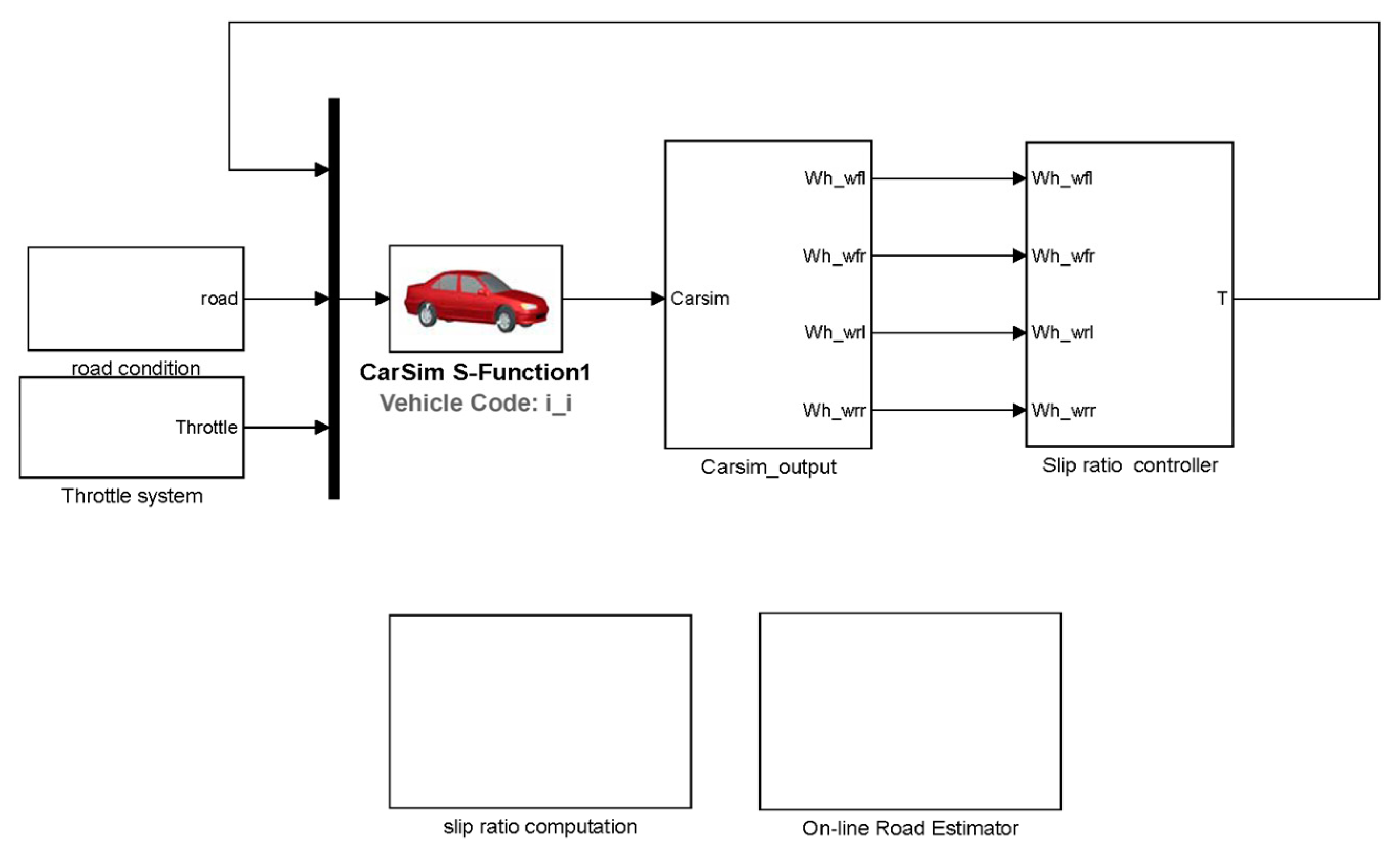
In order to verify the effectiveness of the designed sliding mode controller based on conditional integration, joint simulation analysis is performed by MATLAB/Simulink and CarSim, and the established simulation model is shown in Figure 6.
The simulation of acceleration on joint road and split road are carried out separately, and the key simulation parameters are as listed in Table 2.
In order to show that the designed slip ratio controller based on CISMC can reduce the chattering phenomenon and steady-state error caused by a sliding mode control, the slip ratio controller based on TSMC adopts a fixed optimal slip ratio, and the fixed optimal slip ratio is set at 0.2. The co-simulation models of the slip ratio controller based on CISMC and TSMC are established separately, and simulation experiments are carried out.

4.1. Simulation of Acceleration on Joint Road

The road adhesion coefficient of the first 5 s is set to 0.2, and the last 5 s is set to 0.6. The simulation results are shown in Figure 7.
The simulation results of acceleration on joint road are shown in Figure 7. According to Figure 7a (Slip ratio of left front wheel), the road estimation algorithm can accurately and rapidly estimate the optimal slip ratio of variable roads. The CISMC with adaptive optimal slip ratio control can keep the slip ratio of the left front wheel changed with the road condition, while the slip ratio of the left front wheel based on TSMC with fixed optimal slip ratio control fluctuates around 0.2.
According to Figure 7b (Vehicle speed), the final vehicle speed of CISMC with adaptive optimal slip ratio control of the first 5 s is 12.09 m / s , and the final speed of TSMC with fixed optimal slip ratio control of the first 5 s is 9.73 m / s . The final vehicle speed of CISMC with adaptive optimal slip ratio control of the last 5 s is 47.28 m / s , and the final vehicle speed of TSMC with fixed optimal slip ratio control of the last 5 s is 41.41 m / s .
According to Figure 7c (Longitudinal acceleration), the average longitudinal acceleration of the first 5 s of CISMC with adaptive optimal slip ratio control is 2.42 m / s 2 , and the average longitudinal acceleration of the first 5 s of TSMC with fixed optimal slip ratio control is 1.94 m / s 2 . The average longitudinal acceleration of the last 5 s of CISMC with adaptive optimal slip ratio control is 7.04 m / s 2 , and the average longitudinal acceleration of the last 5 s of TSMC with fixed optimal slip ratio control is 6.33 m / s 2 .
According to Figure 7d (Estimated value of road adhesion), the road estimation algorithm can accurately estimate the adhesion coefficient of the road of the first 5 s at 0.38 s and estimate the adhesion coefficient of the road of the last 5 s at 5.36 s .
From the simulation results of acceleration on joint road, it can be seen that the road estimation algorithm can accurately and rapidly estimate the adhesion coefficient and the wheel’s optimal slip ratio; the CISMC with adaptive optimal slip ratio control can keep the slip ratio of the wheel at the optimal slip ratio based on the driving road conditions; and the CISMC can weaken the chattering phenomenon and steady-state error of the traditional sliding mode control.

4.2. Simulation of Acceleration on Split Road

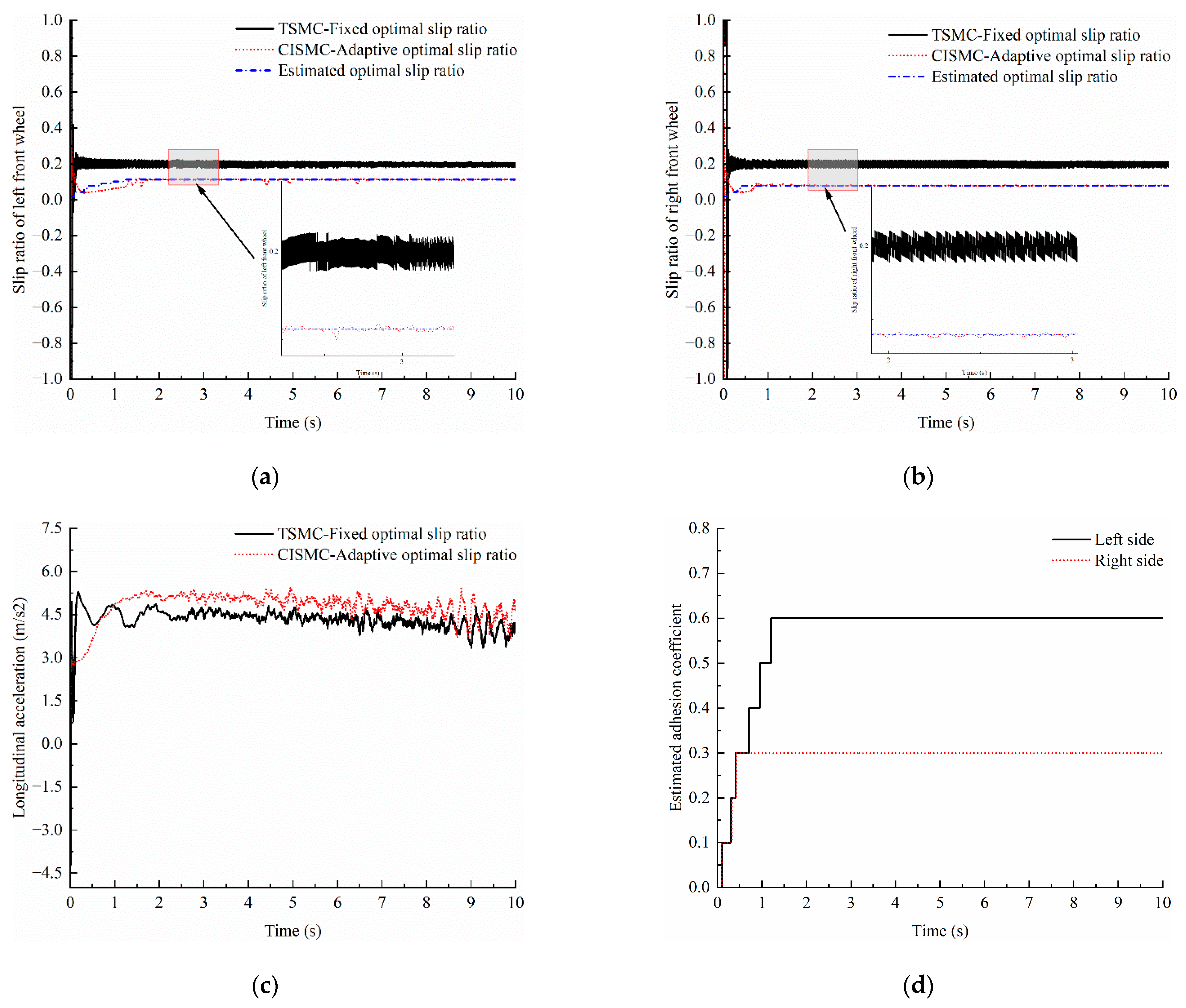
The road adhesion coefficient of the left-side road is set to 0.6, and the road adhesion coefficient of the right-side road is set to 0.3. The simulation results are shown in Figure 8.
The simulation results of acceleration on split road are shown in Figure 8. It can be seen from Figure 8a (Slip ratio of left front wheel) that the CISMC with adaptive optimal slip ratio control can keep the slip ratio of the left front wheel at the estimated optimal slip ratio of 0.11; the slip ratio of the left front wheel based on TSMC with fixed slip ratio control fluctuates around 0.2, and the slip ratio of the left front wheel involves a large steady-state error.
According to Figure 8b (Slip ratio of right front wheel), the CISMC with adaptive optimal slip ratio control can keep the slip ratio of the right front wheel at the estimated optimal slip ratio of 0.076; the slip ratio of the right front wheel based on TSMC with fixed optimal slip ratio control fluctuates around 0.2.
According to Figure 8c (Longitudinal acceleration), the average longitudinal acceleration of CISMC with adaptive optimal slip ratio control is 4.76 m / s 2 , and the average longitudinal acceleration of TSMC with fixed optimal slip ratio control is 4.32 m / s 2 .
According to Figure 8d (Estimated value of road adhesion), the road estimation algorithm can accurately estimate the adhesion coefficient of the left side road at 1.20 s and estimate the adhesion coefficient of the right side road at 0.42 s .
From the simulation results of acceleration on split road, it can be seen that the road estimation algorithm can accurately and rapidly estimate the adhesion coefficient and the wheel optimal slip ratio of the split road; the CISMC with adaptive optimal slip ratio control can keep the slip ratio of the different side wheels at the optimal slip ratio based on the driving road conditions; the CISMC can weaken the chattering phenomenon and steady-state error of the traditional sliding mode control; and the dynamic performance of the vehicle based on CISMC with adaptive optimal slip ratio control is improved.

5. Conclusions

In this paper, to realize the slip ratio adaptive control of the distributed drive electric vehicle, a road estimator based on the Burckhardt tire model is designed, and an adaptive slip ratio controller based on CISMC is designed. In order to improve the accuracy of the optimal wheel slip ratio estimation, the improved estimation principle is analyzed. The input variable of the slip ratio adaptive controller is redesigned to obtain a faster vehicle dynamic response. Finally, joint simulations using MATLAB/Simulink and CarSim are conducted to verify the effectiveness of the designed road estimator and slip ratio adaptive controller based on CISMC. The co-simulation models of the slip ratio adaptive controller based on CISMC and the fixed slip ratio controller based on TSMC are established and simulated separately to compare the control effects. The conclusions are drawn as follows:
(1)
The designed road estimator can quickly and accurately estimate the road adhesion coefficient and the optimal wheel ratio when the vehicle accelerates on joint road; the road estimator can obtain the road adhesion coefficient and optimal slip ratio within 0.38 s , and when the vehicle accelerates on split road, the road estimator can obtain the road adhesion coefficient and optimal slip ratio within 1.20 s .
(2)
Slip ratio adaptive control based on CISMC can weaken the chattering phenomenon of slip ratio fixed control based on TSMC.
(3)
Slip ratio adaptive control based on CISMC can maintain the wheel slip ratio at the optimal value according to the driving road conditions automatically, and the dynamic performance of the vehicle is improved.
The main simulation results of different controllers and road conditions are shown in Table 3.

Author Contributions

Formal analysis, G.Q.; Methodology, S.K.; Supervision, J.C.; Writing—original draft, H.T. All authors have read and agreed to the published version of the manuscript.

Funding

We would like to acknowledge financial support from the Science and Technology Project of Jiangxi Provincial Department of Education (Grant Numbers: GJJ200877), Jiangxi Provincial Natural Science Foundation (Grant Numbers: 20224BAB204039), and Jiangxi Province College Students Innovation and Entrepreneurship Training Program (Grant Numbers: 202110407016).

Data Availability Statement

The data will be made available on request by the corresponding author.

Conflicts of Interest

The authors declare no conflict of interest.

References

  1. Menhour, L.; d’Andréa-Novel, B.; Fliess, M.; Mounier, H. Coupled nonlinear vehicle control: Flatness-based setting with algebraic estimation techniques. Control Eng. Pract. 2014, 22, 135–146. [Google Scholar] [CrossRef]
  2. Yin, D.; Sun, N.; Hu, J. A wheel slip control approach integrated with electronic stability control for decentralized drive electric vehicles. IEEE Trans. Ind. Inform. 2019, 15, 2244–2252. [Google Scholar] [CrossRef]
  3. Wang, J.; Yin, D.; Chen, L.; Du, J. Estimation of road adhesion coefficient for four-wheel independent drive electric vehicle. In Proceedings of the 2020 5th International Conference on Mechanical, Control and Computer Engineering (ICMCCE), Harbin, China, 25–27 December 2020. [Google Scholar]
  4. Leng, B.; Jin, D.; Xiong, L.; Yang, X.; Yu, Z. Estimation of tire-road peak adhesion coefficient for intelligent electric vehicles based on camera and tire dynamics information fusion. Mech. Syst. Signal Process. 2021, 150, 1–15. [Google Scholar] [CrossRef]
  5. Li, S.; Wang, G.; Yang, Z.; Wang, X. Dynamic joint estimation of vehicle sideslip angle and road adhesion coefficient based on DRBF-EKF algorithm. Chin. J. Theor. Appl. Mech. 2022, 54, 1853–1865. [Google Scholar]
  6. Zhang, B.; Chen, Z.; Fu, J.; Chen, B. Self-adaption acceleration slip regulation control of four-wheel independently-driving electric vehicle. J. Shandong Univ. (Eng. Sci.) 2018, 48, 96–103. [Google Scholar]
  7. Guo, W.; Duan, M.; Li, G.; Yu, Q. Study on Acceleration Slip Regulation Control of Electric Vehicle Based on Fuzzy PID Controller. Agric. Equip. Veh. Eng. 2015, 53, 38–42+51. [Google Scholar]
  8. Tao, W.; Yu, H.; Huang, M. Fuzzy Anti-Slip Regulation Based on Optimal Slip Ratio Recognition for In-wheel Motor Driving Electric Vehicle. J. Wuhan Univ. Technol. 2015, 37, 47–52+70. [Google Scholar]
  9. Saha, S.; Syed, M. Design of slip-based traction control system for EV and validation using co-simulation between Adams and Matlab/Simulink. Simulation 2020, 96, 537–549. [Google Scholar] [CrossRef]
  10. Nam, K.; Yoichi, H.; Lee, C. Wheel Slip Control for Improving Traction-Ability and Energy Efficiency of a Personal Electric Vehicle. Energies 2015, 8, 6820–6840. [Google Scholar] [CrossRef]
  11. Eicke, S.; Busch, A.; Wielitzka, M.; Zemke, S. Tire Road friction estimation for improvements to traction control during drive off maneuvers in vehicles. In Proceedings of the 2016 IEEE Conference on Control Applications (CCA), Buenos Aires, Argentina, 19–22 September 2016. [Google Scholar]
  12. Yu, D.; Wang, W.; Zhang, H.; Xu, D. Research on anti-lock braking control strategy of distributed-driven electric vehicle. IEEE Access 2020, 8, 162467–162478. [Google Scholar] [CrossRef]
  13. Guo, L.; Xu, H.; Zou, J.; Xu, H.; Zheng, G. Variable gain control-based acceleration slip regulation control algorithm for four-wheel independent drive electric vehicle. Trans. Inst. Meas. Control 2021, 43, 902–914. [Google Scholar] [CrossRef]
  14. Peng, M.; Karimi, H.; Yang, S.; Xu, B.; Huang, C. An adaptive fuzzy sliding-mode control for regenerative braking system of electric vehicles. Int. J. Adapt. Control Signal Process. 2022, 36, 391–410. [Google Scholar]
  15. Hegazy, S.; Sandu, C. Experimental investigation of vehicle mobility using a novel wheel mobility number. J. Terramech. 2013, 50, 303–310. [Google Scholar] [CrossRef]
  16. Ding, X.; Zhang, L.; Wang, Z.; Liu, P. Acceleration Slip Regulation for Four-Wheel-Independently-Actuated Electric Vehicles Based on Road Identification through the Fuzzy Logic. IFAC-PapersOnLine 2018, 51, 943–948. [Google Scholar] [CrossRef]
  17. Wang, B.; Guan, H.; Lu, P.; Zhang, A. Road surface condition identification approach based on road characteristic value. J. Terramech. 2014, 6, 103–117. [Google Scholar] [CrossRef]
  18. Zhou, W.; Li, J.; Zhang, S.; Tang, S. Vehicle Acceleration Slip Regulation Using Extreme Value Search Algorithm to Estimate Adhesion Coefficient. J. Huaqiao Univ. (Nat. Sci.) 2019, 40, 701–706. [Google Scholar]
  19. Liao, Z.; Liu, D.; Yang, G.; Liu, D. Integrated control of ABS and ASR for multi-wheel independent electric drive vehicle. Mech. Electr. Eng. Mag. 2018, 35, 494–500. [Google Scholar]
  20. Mehrdad, E.; Yimin, G.; Ali, E. Modern Electric, Hybrid Electric, and Fuel Cell Vehicles: Fundamentals, Theory, and Design; CRC Press: Boca Raton, FL, USA, 2005. [Google Scholar]
  21. Ivanov, V.; Savitski, D.; Shyrokau, B. A Survey of Traction Control and Antilock Braking Systems of Full Electric Vehicles With Individually Controlled Electric Motors. IEEE Trans. Veh. Technol. 2014, 64, 3878–3896. [Google Scholar] [CrossRef]
  22. Incremona, G.; Regolin, E.; Mosca, A.; Incremona, G. Sliding mode control algorithms for wheel slip control of road vehicles. In Proceedings of the 2017 American Control Conference (ACC), Seattle, WA, USA, 24–26 May 2017. [Google Scholar]
  23. Guo, H.; Yu, R.; Bai, X.; Chen, H. Vehicle traction control based on optimal slip using sliding mode controller. In Proceedings of the 33rd Chinese Control Conference, Nanjing, China, 28–30 July 2014. [Google Scholar]
  24. Yokoyama, M.; Kim, G.; Tsuchiya, M. Integral Sliding Mode Control with Anti-windup Compensation and its Application to a Power Assist System. J. Vib. Control 2010, 16, 503–512. [Google Scholar] [CrossRef]
  25. Liu, D.; Liao, Z.; Yang, G.; Chen, L. Acceleration Slip Regulation of Multi-wheel Independent Electric Drive Vehicle Based on Sliding Mode Control. Mod. Manuf. Technol. Equip. 2017, 15–19. [Google Scholar] [CrossRef]
  26. Maeda, K.; Fujimoto, H.; Hori, Y. Four-wheel driving-force distribution method for instantaneous or split slippery roads for electric vehicle. Autom. Časopis Za Autom. Mjer. Elektron. Računarstvo I Komun. 2013, 54, 103–113. [Google Scholar] [CrossRef]
  27. Yoshimura, M.; Fujimoto, H. Driving torque control method for electric vehicle with in-wheel motors. Electr. Eng. Jpn. 2012, 181, 49–58. [Google Scholar] [CrossRef]
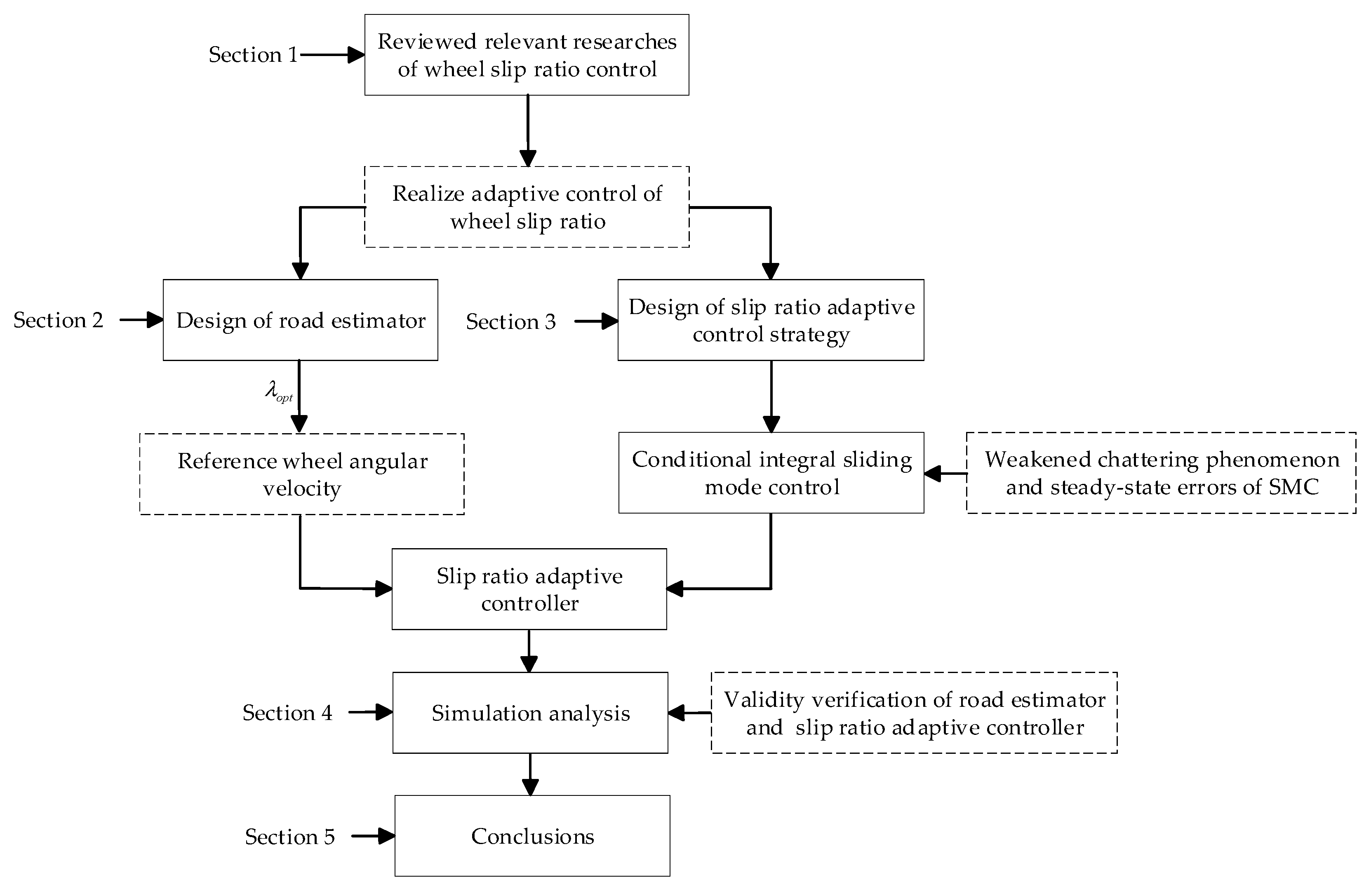
Figure 1. The main framework of the paper.
Wevj 14 00119 g001
Figure 2. Single wheel model.
Wevj 14 00119 g002
Figure 3. Improved estimation principle of optimal slip ratio.
Wevj 14 00119 g003
Figure 4. λ o p t μ max curve of standard roads.
Wevj 14 00119 g004
Figure 5. λ o p t μ max fit curve of standard roads.
Wevj 14 00119 g005
Figure 6. Established simulation model.
Wevj 14 00119 g006
Figure 7. Simulation results of acceleration on joint road. (a) Slip ratio of left front wheel; (b) Vehicle speed; (c) Longitudinal acceleration; (d) Estimated value of road adhesion.
Wevj 14 00119 g007
Figure 8. Simulation results of acceleration on split road. (a) Slip ratio of left front wheel; (b) Slip ratio of right front wheel; (c) Longitudinal acceleration; (d) Estimated value of road adhesion.
Wevj 14 00119 g008
Table 1. The C 1 , C 2 , C 3 of different roads [17].
Road Type C 1 C 2 C 3
Dry asphalt1.28123.9930.520
Dry cement1.19625.1660.539
Wet asphalt (big)1.02729.4940.442
Wet asphalt (middle)0.85633.8210.345
Wet asphalt (small)0.62833.7680.200
Wet goose soft stone0.40060.0100.120
Snow covered road0.19594.1290.065
Ice pavement0.050306.3900.001
Table 2. Key simulation parameters.
ParameterValue
Vehicle mass ( kg )1231
Wheel effective radius ( m )0.311
Distance from front axle to CG ( m )1.04
Distance from rear axle to CG ( m )1.56
Height of CG above ground ( m )0.54
Rotational inertia of the wheel ( kg m 2 )0.6
Table 3. Main simulation results.
Controller TypeRoad ConditionSlip Ratio Vehicle   Speed   ( m / s ) Average   Longitudinal   Acceleration   ( m / s 2 )
CISMC-Adaptive optimal slip ratioJoint road0.06 (μ = 0.2)12.092.42
0.11 (μ = 0.6)47.287.04
TSMC-Fixed optimal slip ratio0.2 (μ = 0.2)9.731.94
0.2 (μ = 0.6)41.416.33
CISMC-Adaptive optimal slip ratioSplit road0.11 (μ = 0.6)-4.76
0.08 (μ = 0.3)
TSMC-Fixed optimal slip ratio0.2 (μ = 0.6)-4.32
0.2 (μ = 0.3)
Disclaimer/Publisher’s Note: The statements, opinions and data contained in all publications are solely those of the individual author(s) and contributor(s) and not of MDPI and/or the editor(s). MDPI and/or the editor(s) disclaim responsibility for any injury to people or property resulting from any ideas, methods, instructions or products referred to in the content.