Article

Variable Switching Frequency Deadbeat Predictive Current Control for PMSM with High-Speed and Low-Carrier Ratio

1
School of Electrical Engineering, Tiangong University, Tianjin 300387, China
2
Baodi Power Supply Branch of State Grid Tianjin Electric Power Company, Tianjin 301800, China
*
Author to whom correspondence should be addressed.
World Electr. Veh. J. 2023, 14(3), 64; https://doi.org/10.3390/wevj14030064
Submission received: 6 February 2023 / Revised: 22 February 2023 / Accepted: 1 March 2023 / Published: 3 March 2023
(This article belongs to the Special Issue Electrical Machines Design and Control in Electric Vehicles)

Abstract

:
The predictive current control method of permanent magnet synchronous motor has the advantages of fast dynamic response and easy digital implementation, so more attention has been paid to it. When the motor operates in a high-speed condition, the switching frequency is relatively low, the carrier ratio is low, and the rotor angle varies greatly within a control cycle, resulting in a large error in the traditional liner approximation prediction model and inaccuracy of the voltage control quantity calculation, which leads to the deterioration of the predictive current control effect. At the same time, the output harmonic of the three-phase current increases, which affects the stable operation of the motor. In this paper, we study the causes of the large errors in the prediction model based on the traditional linear approximation and phase current fluctuation of the permanent magnet synchronous motor under high speed and low carrier-ratio conditions. Based on the improvement of the prediction model and modulation, a new control strategy of variable switching frequency deadbeat predictive current control is proposed. The control method proposed in this paper improves the dynamic and steady-state performance of the motor, under the condition that the carrier ratio does not increase and reduces the fluctuation of the output current of the motor. Finally, the effectiveness and superiority of the proposed method are verified by an experiment.

1. Introduction

A fast and stable current loop is essential for the reliable operation of the permanent magnet synchronous motor (PMSM). The current loop control methods mainly include field-oriented control, predictive control, and so on [1,2,3,4]. The deadbeat predictive current control has a constant switching frequency, which has the advantages of simple discrete model establishment, easy algorithm implementation, and high control bandwidth, so it has attracted a great deal of attention [5,6,7]. However, for the current loop, its dynamic and steady-state performance is mainly affected by the switching frequency of power devices and digital control delay [8,9].
Therefore, to ensure the dynamic and steady-state performance of current control, it is usually necessary to increase the switching frequency of power devices to ensure that the control system has the corresponding carrier ratio. However, for high-speed motors, due to the limited switching frequency of power devices, the carrier ratio will inevitably decrease with the increase of motor speed [10]. At this point, for traditional deadbeat predictive current control, the delay effect of the digital control system will increase significantly and affect the dynamic and steady-state performance of the entire control system seriously [11].
Given the above problems, in [12], the author analyzed the stability of the current loop influence of the delay caused by space vector modulation on the surface permanent magnet synchronous motor (SPMSM). In [13], the author analyzed the problem that the current loop is unstable when the motor runs at the high-speed condition and adopts an improved PI controller. The PI controller designed can realize angle compensation to improve the current loop’s performance. In [14], the author modeled and analyzed the influence of angle delay and time delay caused by digital control on the stable operation of the permanent magnet synchronous motor system. In [15], the author pointed out that when the permanent magnet synchronous motor operates under high carrier ratio conditions, to simplify the calculation, the predictive current equation approximates a set of linear equations by using the mathematical limit principle. However, the predictive current equation has a large error when the motor operates under high speed and low carrier ratio conditions. It is difficult to accurately complete the delay compensation, resulting in a decrease in the control performance. In [16], the author further analyzed when the motor speed increases and the carrier ratio decreases under the premise that the switching frequency remains unchanged, and the change of rotor angle position in a control cycle cannot be ignored, which leads to an increase of the error of the back electromotive force (EMF) in the motor model and the decrease of the control performance of the motor. In [17], a new continuous time-domain prediction model was established by solving the differential equation of the SPMSM for the errors existing in the first-order Euler equation under low carrier ratio conditions. However, this algorithm has high complexity. In [18], it analyzes the error of the discrete equation approximated by the traditional forward Euler method under low carrier. It obtains a new prediction model to compensate the delay of the control quantity by solving the state equation to establish a prediction model suitable for high speed and low carrier ratio conditions. In [19], a hybrid modulation was proposed—that SVPWM in a dynamic state and SHMPWM in a steady state solve the current fluctuation and harmonics caused by the operation of low carrier ratio condition. However, this method requires frequent switching of modulation strategies, and the dynamic performance is difficult to guarantee.
Above all, when the motor is running at high speed and low carrier ratio conditions, the main reasons leading to the performance decline of traditional deadbeat predictive current control can be summarized as two points: one is the large rotor position angle error in a control cycle, where the error of the back EMF in the discrete model increases, which makes it difficult for the traditional prediction model to calculate the accurate voltage control quantity, and decreases the control performance of the motor at high speed and low carrier ratio conditions. Another reason is that when the traditional sampling and update strategy (duty cycle update) of SVPWM is adopted, the current fluctuation and harmonics increase when the motor runs at low carrier ratio conditions, which further increases the error of reference voltage calculation in the deadbeat algorithm. It is also essential that the traditional strategy easily causes control instability when the motor is running at high-speed conditions.
In order to solve the above problems, a discrete mathematical model considering the error of rotor angle variation in a control cycle was established based on the deadbeat predictive current control. At the same time, through the establishment of a modulation strategy mapping relationship between the steady-state current waveform quality, a modulation strategy combining switching state clamping and space vector modulation and duty ratio update method was designed. A new deadbeat predictive current control method with variable switching frequency was proposed by combining the control algorithm with the modulation strategy. This was compared with the traditional control method, which not only ensures the dynamic performance of the current but also improves the steady-state quality of the current when the motor is running at high speed and low carrier ratio conditions.

2. Deadbeat Predictive Current Control Principle and Error Analysis

The PMSM is a strongly coupled nonlinear system, and to simplify the analysis of modeling, the flux saturation and losses should be ignored. Taking SPMSM as an example, the mathematical model in the d-q axis can be expressed as (1) [17].
d i d t = A i + B u + C
and,  i = [ i d i q ] u = [ u d u q ] A = [ R s / L s ω e ω e R s / L s ] B = [ 1 / L s 0 0 1 / L s ] C = [ 0 ω e ψ f / L s ] .
Where the d and q denote the d- and q-axis components, respectively, and i and u are the current and voltage vectors. ωe is the electric rotor speed, and Ls and Rs are the stator inductance and resistance, respectively. ψf is the rotor permanent magnet flux linkage. (1) can be calculated and obtained as the current equation on the d-q axis by Laplace:
i ( t ) = e ( t t 0 ) A i ( t 0 ) + t 0 t e ( t τ ) A [ B u ( τ ) + C ] d τ
where τ is the integral variable of time and t0 is the start time of the calculation.
The continuous time domain must be discretized in digital signal processors with a fixed step size. The electric rotor speed ωe, the control voltage u, and the back EMF phase C are generally considered as constant between the two adjacent sampling moments kT and (k + 1)T. At this point, the predictive current equation can be approximated as:
i ( k + 1 ) = D ( k ) i ( k ) + A 1 ( D E ) B u ( k ) + A 1 ( D E ) C ( k )
and,  D ( k ) = e A T = e R s L s T [ cos ω e T sin ω e T sin ω e T cos ω e T ] E = [ 1 0 0 1 ] .
However, if the motor runs at a high carrier ratio condition, ωe*T will be very small. According to the mathematical limit approximate principle, the current equation can be approximated, as shown in (4):
{ e R s L s T 1 R s L s T sin ω e T ω e T cos ω e T 1
Taking (4) into (3), the current prediction model after linear approximation can be written as:
{ i d ( k + 1 ) = ( 1 T R s L s ) i d ( k ) + T ω e ( k ) i q ( k ) + u d ( k ) T L s i q ( k + 1 ) = ( 1 T R s L s ) i q ( k ) + T ω e ( k ) i d ( k ) T ω e ( k ) ψ f + u q ( k ) T L s
Due to the inherent delay of the numerical control system, it is necessary to make a delay compensation for the control algorithm. According to the principle of deadbeat control, i(k + 1) = i*(k), i*(k) represents the reference value of stator current at k-moment, so the control voltage of the next control cycle can be calculated according to (5), as shown in (6):
{ u d pre ( k + 1 ) = R s i d ( k + 1 ) + L s T [ i d * ( k ) i d ( k + 1 ) ] ω e ( k ) L s i q ( k + 1 ) u q pre ( k + 1 ) = R s i q ( k + 1 ) + L s T [ i q * ( k ) i q ( k + 1 ) ] + ω e ( k ) L s i d ( k + 1 ) + ω e ( k ) ψ f
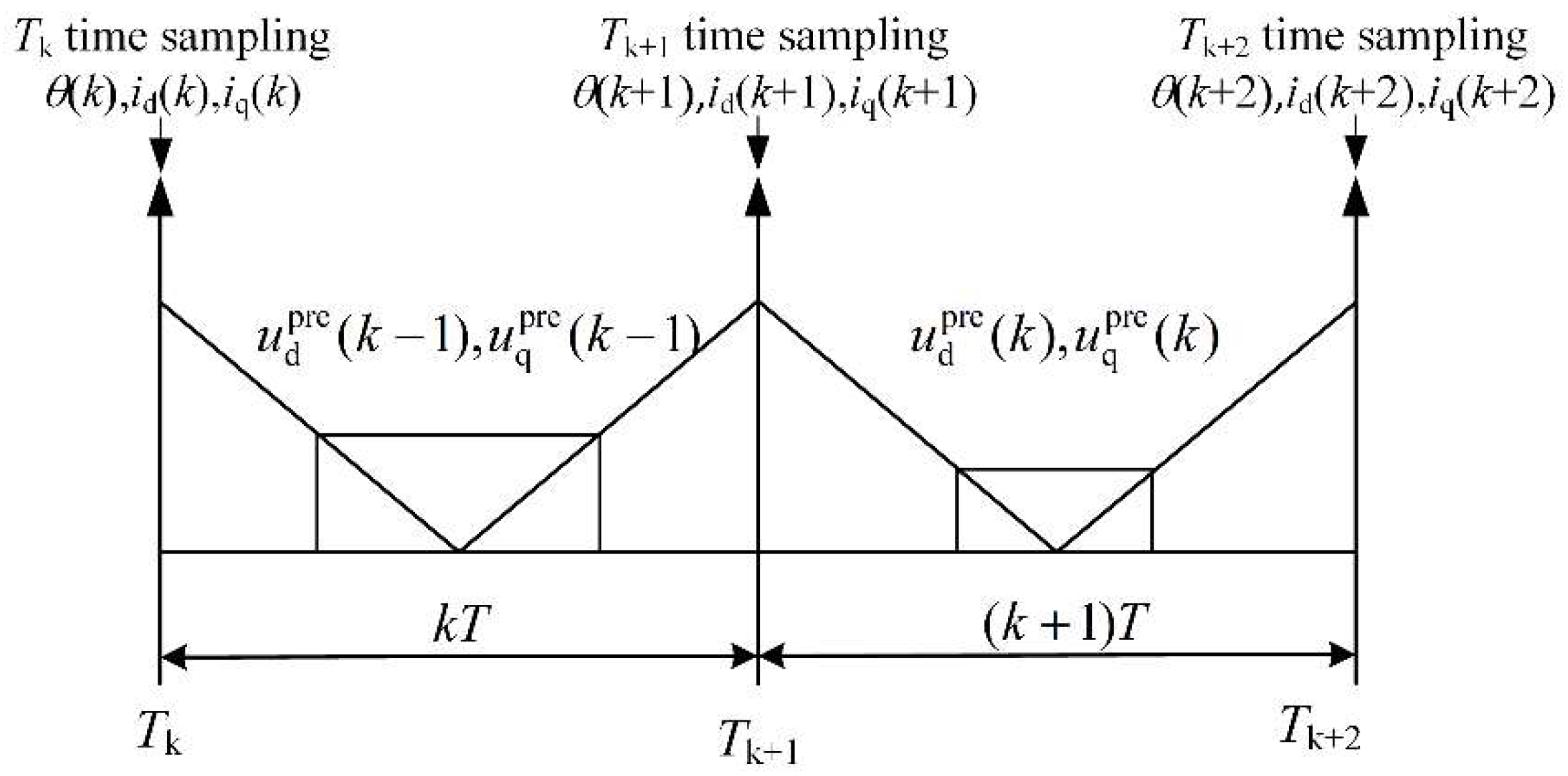
As shown in Figure 1, the reference voltage vector applied at k + 1-moment was calculated at k-moment according to (6). Due to digital control, the control system at k-moment will lock a fixed set of voltage vectors, and the actual output voltage of the inverter can be considered to remain unchanged within a carrier cycle. However, in practice, the amplitude and angle of the reference voltage vector and actual output value should change accordingly in one carrier cycle. In the traditional modulation algorithm, sampling and control algorithms are executed once in a carrier cycle. The correspondence between the current sampling time and the PWM duty-on ratio update time is shown in Figure 2. Due to the existence of control delay and the limitation of hardware conditions, the control voltage calculated at the initial time of the kT control cycle cannot be updated until the (k + 1)T control cycle, and it works until the end of the (k + 1)T control cycle. In this update, an angle deviation for a control cycle is ωeT, and this value can reach dozens of degrees when the motor is running at high speed and low carrier ratio conditions. In the end, when the traditional deadbeat predictive control operates at low carrier ratio conditions, the stator current tracking has a large static difference, leading to very serious control errors and current fluctuations [18].

3. Variable Switching Frequency Deadbeat Predictive Current Control

This section targets the following problem: that traditional deadbeat predictive control is difficult for calculating accurate control quantity under high speed and low carrier ratio conditions, and the stator current tracking performance is poor. An improved current prediction model considering the change of rotor position in a control cycle was derived, and a clamping modulation strategy was designed using the over-sampling mode. Based on the established model and modulation strategy, a novel deadbeat predictive current control method was proposed to realize the variable switching frequency of deadbeat predictive current control, which ensures the high dynamic and low harmonic current of the motor under high speed and low carrier ratio conditions.

3.1. Improved Prediction Model Suits Low Carrier Ratio Condition

Compared with the d-q axis, the voltage equation on the α-β axis has no cross-coupling term, and the voltage vector error caused by the angle error in the coordinate changes can be ignored. Therefore, this paper deduces the improved current prediction model based on the α-β axis.
First, the voltage equation based on the α-β axis can be expressed as:
{ u α = R s i α + L s d d t i α ω e ψ f sin ( θ e ) u β = R s i β + L s d d t i β ω e ψ f cos ( θ e )
The current equation on the α-β axis can be rewritten to:
{ d d t i α = 1 L s ( u α R s i α + ω e ψ f sin ( θ e ) ) d d t i β = 1 L s ( u β R s i β + ω e ψ f cos ( θ e ) )
(8) can be reduced to:
d i ( t ) d t = 1 L s [ R s i ( t ) + u ( t ) + e ( t ) ]
The effect of resistance is largely negligible when the motor is running at a high-speed condition. The rate of change of i(t) depends on the relationship between u(t) and e(t), and the previous analysis shows that the u(t) has the effect of a zero-order retainer on the α-β axis, so it can be considered to be constant in a control cycle. The angle of the back EMF vector e(t) is the same as the rotor position angle of the motor and keeps rotating in space. Under low carrier ratio conditions, a control cycle’s rotation angle of e(t) can reach tens of degrees. Therefore, when the motor is running at high speed and low carrier ratio condition, the change of rotor angle position cannot be ignored.
The predictive current for the k + 1-moment can be expressed as:
i ( k + 1 ) = i ( k ) + Δ i ( T )
i(k) can be obtained by current sampling, and Δi(T) is mainly affected by u(t) and e(t) in a control cycle when the motor is running at a high-speed condition. The variation of e(t) needs to be taken into account in the discrete model, and Δi(T) in a control cycle can be expressed as:
{ Δ i α ( T ) = 0 T d i α ( t ) d t d t R s i α ( k ) + u α ( k ) T + ψ f [ cos ( θ ( k ) + ω e T ) cos θ ( k ) ] L s Δ i β ( T ) = 0 T d i β ( t ) d t d t R s i β ( k ) + u β ( k ) T + ψ f [ sin ( θ ( k ) + ω e T ) sin θ ( k ) ] L s
The current prediction model considering the change of rotor angle position in the unit control cycle based on the α-β axis can be expressed as:
{ i α ( k + 1 ) = ( 1 R s T L s ) i α ( k ) + T L s u α ( k ) ψ f L s [ cos ( θ ( k ) + ω e T ) cos θ ( k ) ] i β ( k + 1 ) = ( 1 R s T L s ) i β ( k ) + T L s u β ( k ) ψ f L s [ sin ( θ ( k ) + ω e T ) sin θ ( k ) ]
According to the principle of deadbeat control, the control voltage can be obtained by ordering i(k + 1) = i*(k). Due to a control delay in the motor system, delay compensation of a control cycle is needed to make the control voltage more accurate. The predictive control voltage of the α-β axis can be obtained by taking the predictive current of (12) as the delay compensation, as shown in (13).
{ u α pre ( k + 1 ) = L s T i α * ( k ) L s R s T T i α ( k + 1 ) + ψ f T ( cos ( θ ( k ) + ω e T ) cos ( θ ( k ) ) u β pre ( k + 1 ) = L s T i β * ( k ) L s R s T T i β ( k + 1 ) + ψ f T ( sin ( θ ( k ) + ω e T ) sin ( θ ( k ) )
An improved discrete model considering rotor position angle variation is established in this paper.
From the above analysis, in addition to the influence of the prediction model, another factor that decreases the predictive current control performance at a high-speed condition is the increase of current harmonics caused by the decrease of carrier ratio, which further increases the calculation error of the reference voltage vector in the deadbeat predictive current algorithm. Increasing the switching frequency can reduce this effect, but it is difficult to increase the switching frequency significantly due to economic factors. The traditional deadbeat predictive current control strategy with fixed switching frequency cannot guarantee better current control quality, even if it adopts the improved prediction model established in this paper. Therefore, based on the improved prediction model, this paper proposes a deadbeat predictive current control strategy with variable switching frequency to ensure that the current control quality can be improved without increasing the switching frequency of power devices.
Compared with the traditional deadbeat predictive current control, the control frequency of the proposed method is still fixed, but the actual switching frequency of each power device varies from the scale of a stator current operation cycle. The main reason for this phenomenon is that the proposed method adopts the mode of alternating clamping of a phase bridge arm in a unit stator current operation cycle and coordinates with the switching sequence arrangement mode of adjusting the synthetic space vector so that the switching state of a phase power device does not change in a certain period of a stator current operation cycle, and the switching state of another phase power device is adjusted several times. Thus, the variable switching frequency control of power devices within a unit stator current operation cycle is realized. The implementation method and principle are explained in detail in the next section.

3.2. Clamping PWM Modulation Strategy

When the motor runs at high speed and low carrier ratio conditions, the amplitude of current fluctuations and the total harmonic distortion (THD) of the current are large. Therefore, it is necessary to analyze the relationship between power devices switching state and current fluctuation. Since the phase difference of the ABC phase is 120°, this paper takes the analysis of the A-phase current ripple as an example. According to the relationship between the three-phase static coordinate system and the two-phase static coordinate system, A-phase current and voltage can be expressed as:
u A = u α , i A = i α
Bring (14) into (7):
u A = R s i A + L s d d t ( i A ) ω e ψ f sin ( θ e )
The harmonics of PMSM can be divided into low-frequency harmonics and high-frequency harmonics. For low-frequency harmonics, they can be reduced by optimizing the motor design and improving the magnetic field distribution of the permanent magnet [20]. For high-frequency harmonics, it is necessary to design an improved algorithm and optimize the modulation strategy to reduce the harmonic content. Assuming that the input voltage contains only high-frequency harmonics, the A-phase fundamental voltage can be approximated:
u A = R s i Af + L s d d t ( i Af ) ω e ψ f sin ( θ e )
Therefore, the harmonic voltage equation can be obtained:
u Ah = u A u Af
where the uA is the instantaneous voltage and the uAf is the fundamental voltage.
Because the effect of resistance is largely negligible when the motor is running at a high-speed condition, (18) can be obtained from Equation (16):
u Ah L s d i Ah d t
As seen from (14), uAf can be represented by uα. uA can be synthesized by calculating the basic voltage vector [21]. Therefore, the calculation formula of A phase current harmonic is shown in (19):
Δ i Ah = Δ T u A u α L s
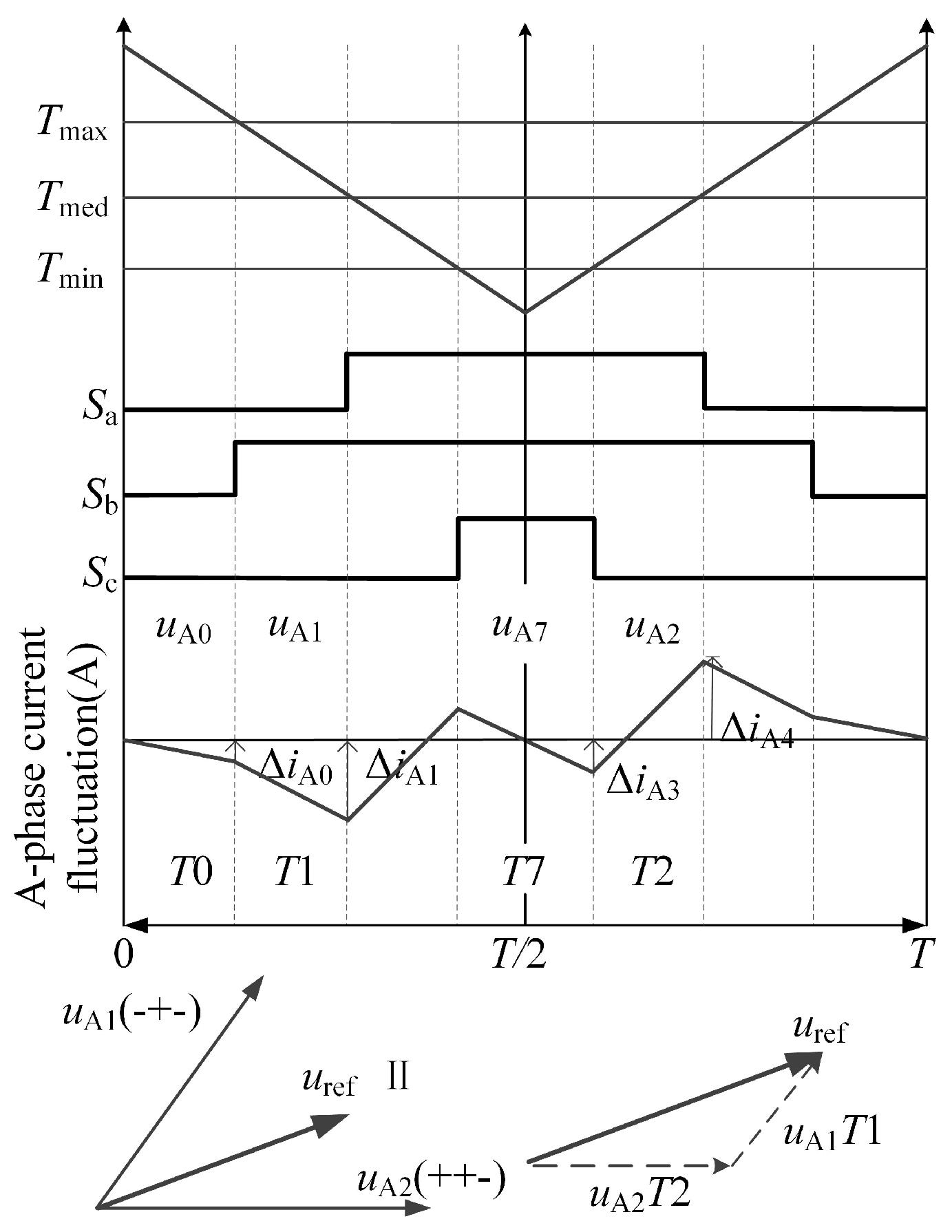
Taking sector II as an example, when the motor adopts the traditional SVPWM modulation strategy, the switching state and current fluctuation within a carrier cycle, as shown in Figure 3, where uA0 and uA7 are zero vectors and T0 and T7 are their duration. uA1 represents the first effective voltage vector synthesized by the three-phase switching action of the inverter in the first half of the carrier cycle, T1 is its duration, uA2 represents the first effective voltage vector in the second half of the carrier cycle, and T2 is its duration. The effective voltage vector combined with its action time can generate control voltage applied to the motor.
The A phase current fluctuation generated by each voltage vector acting on the motor can be calculated by (19), as shown in (20) and (21).
{ Δ i A 0 = u A 0 u Af 0 L s T 0 Δ i A 1 = u A 1 u Af 1 L s T 1 Δ i Amax = max { | Δ i A 0 | , | Δ i A 0 + Δ i A 1 | }
{ Δ i A 0 = u A 7 u Af 7 L s T 7 Δ i A 1 = u A 2 u Af 2 L s T 2 Δ i Amax 1 = max { | Δ i A 3 | , | Δ i A 3 + Δ i A 4 | }
The maximum fluctuation of A phase current in the first and second half carrier cycles can be obtained. The improved prediction model proposed in this paper and the control algorithm based on the traditional SVPWM modulation strategy were simulated and analyzed when the motor ran at different conditions. Following that, (20) and (21) were used to analyze the A phase current fluctuations.
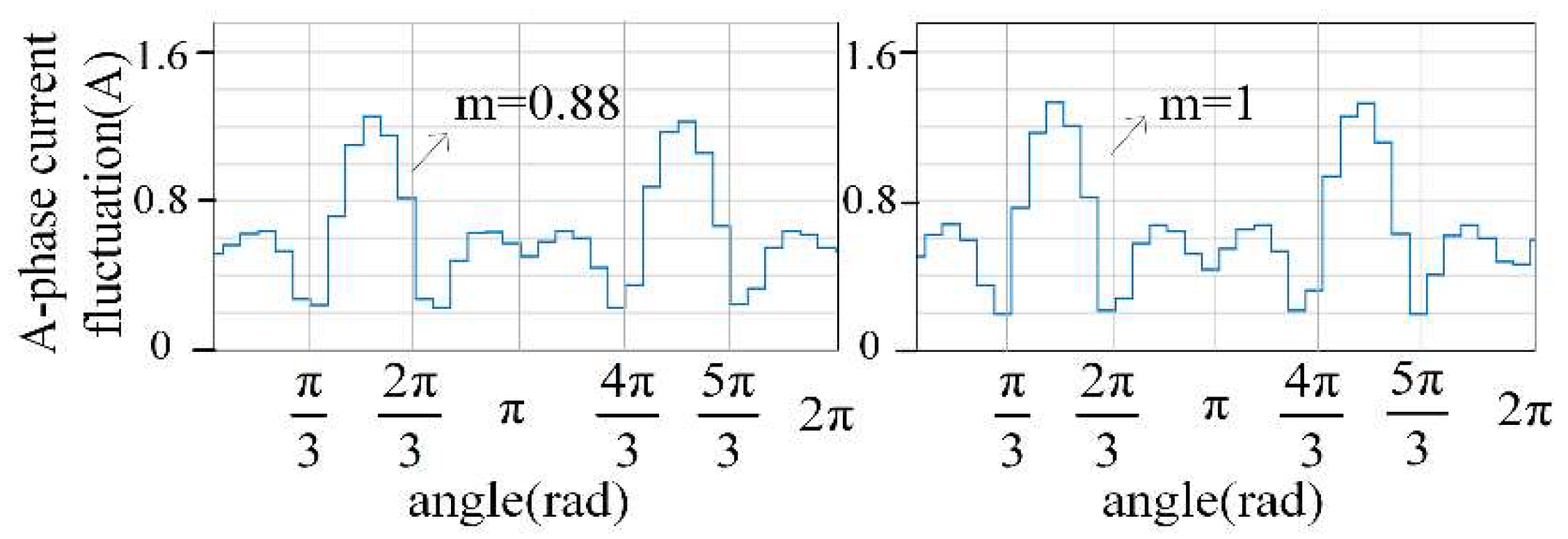
Figure 4 shows the A phase current fluctuation when the modulation degree is 0.88 and 1, respectively. At this point, the motor is running at 8000 r/min and the switching frequency is 5 kHz.
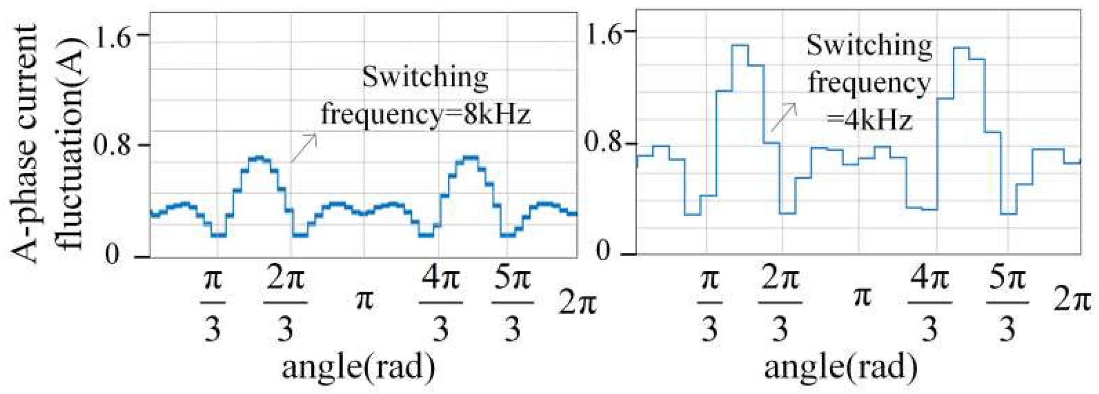
Figure 5 shows the A phase current fluctuation when the modulation degree is 1. At this point, the motor is running at 8000 r/min and the switching frequency is 8 kHz and 4 kHz, respectively.
Figure 4 and Figure 5 show that the A phase current fluctuation is very large and significantly higher than the other sectors in sectors II and V. Therefore, this phenomenon will be analyzed and improved. It is worth noting that the current fluctuation analysis is based on the A phase. The B and C phase current fluctuation is consistent but is behind the A phase 2/3π and 4/3π.
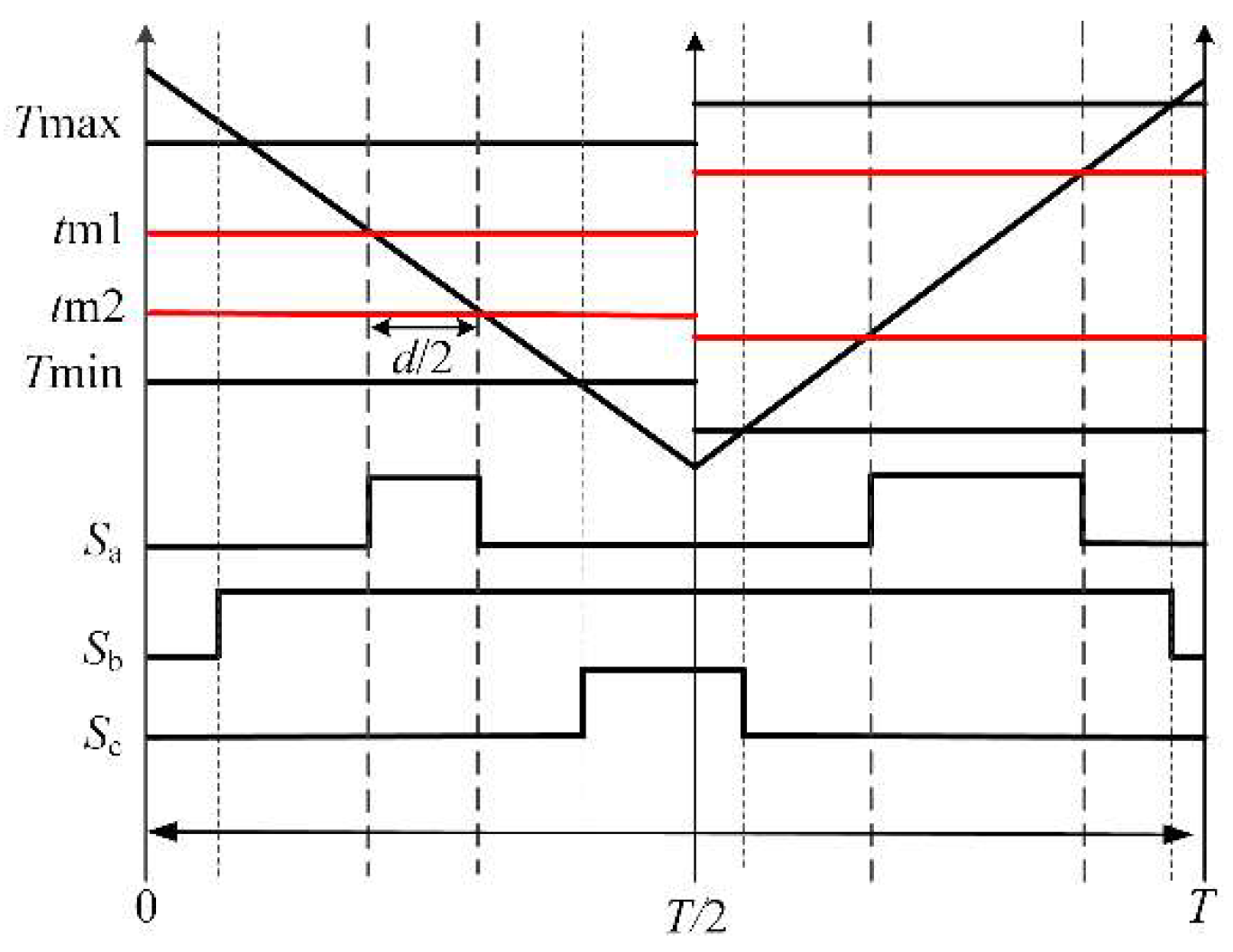
Taking sector II as an example, it can be seen from the above analysis that when the motor is running at a high-speed condition, the dwell time of the effective vector will increase, and the current fluctuation will become very large. In order to reduce the current fluctuation generated by uA1 and uA2, it can be considered to split their action times, which can theoretically halve the amplitude of the current fluctuation. The two parts of a carrier cycle can be regarded as two independent control cycles. Therefore, this paper sets the control algorithm to be executed twice in a carrier cycle so that the voltage vectors can be synthesized twice in each carrier cycle [22]. Sampling and control are carried out at both the beginning and middle of a carrier cycle to further reduce the delay error and improve the accuracy of the algorithm, as shown in Figure 6.
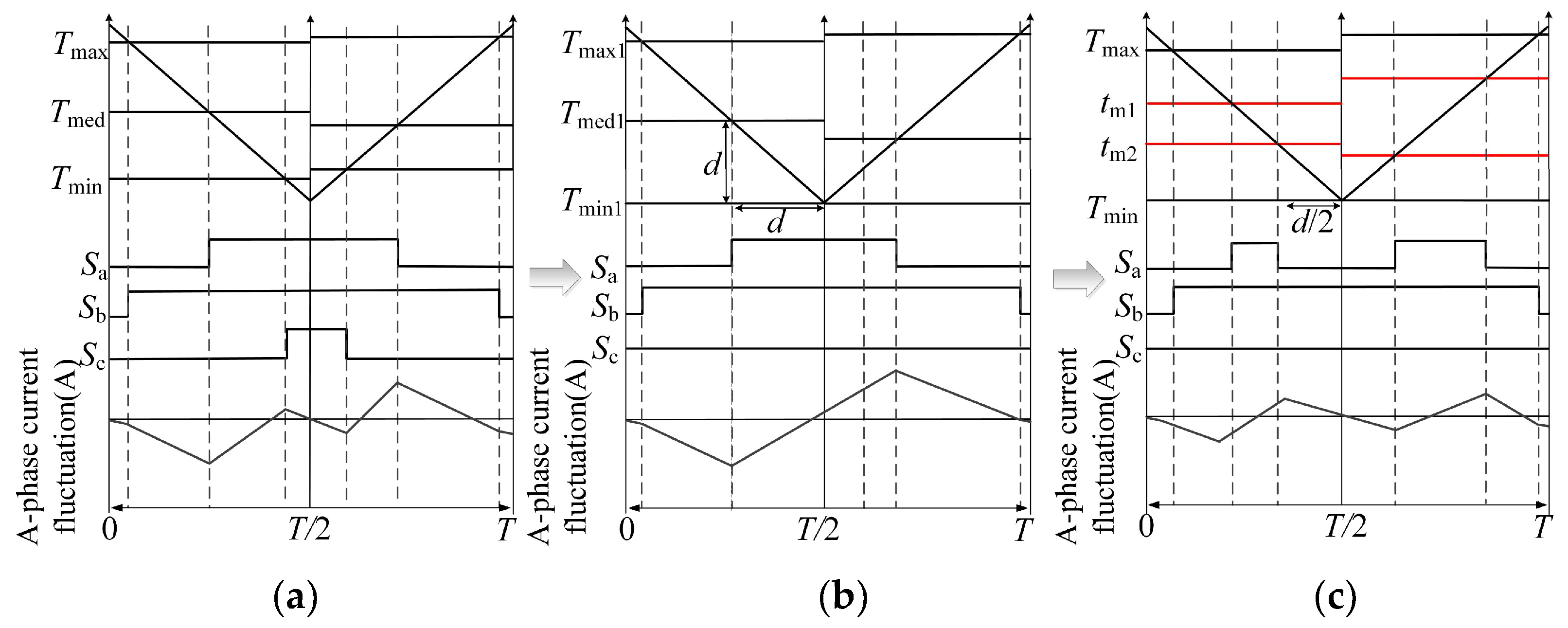
The modulation strategy increases the switching frequency, as shown in Figure 6, which is difficult to meet the requirements of actual working conditions. According to existing research, when the motor is running at a high-speed condition, the modulation degree is a large value, and the zero vector operation time is relatively short [23]. Therefore, the three phase duty ratio Ta, Tb, and Tc(Ta, Tb, Tc∈(0,1)) can be analyzed and adjusted, which are denoted as Tmax, Tmed, and Tmin in Figure 7. As shown in Figure 7, the formation process of the improved clamping modulation strategy is demonstrated, as shown in Figure 7a for the traditional modulation strategy, the c-phase bridge leg acts once in the unit carrier cycle, but when the motor is running at high speed, the modulation degree is high, and the c-phase bridge leg action time is very short, so the modulation strategy shown in Figure 7b was used to clamp this bridge leg. According to (21) and (22), the duty cycle was recalculated, and Tmed was readjusted to obtain the improved clamping modulation strategy proposed in this paper, as shown in Figure 7c. At this time, the middle phase bridge leg operates twice in the unit carrier cycle, reducing the continuous action time of the active vector, which will facilitate the reduction of current fluctuations. Thus, the variable switching frequency control of the power devices within a unit stator current cycle was realized without increasing the switching frequency, and the improved strategy reduces the current ripple and improves the current quality.
The double-sampling and double-updating non-clamping modulation strategy is gradually adjusted to the improved clamping modulation strategy used in this paper. Within a carrier cycle, the smallest phase is always in a clamping state through (21), and the duty ratio of the other two phases is recalculated, as shown in Figure 7b.
{ T max 1 = 1 T med 1 = T med + 1 T max T min 1 = T min + 1 T max
Then, the active time of the intermediate vector was divided by (22). The intermediate phase Tmed1 was divided into two segments, respectively: tm1 and tm2, as shown in Figure 7c, which realizes the splitting of the intermediate active vector and effectively reduces the A phase current fluctuation.
{ t m 1 = 1 d / 2 t m 2 = T med 1 d / 2 d = T med 1 T min 1
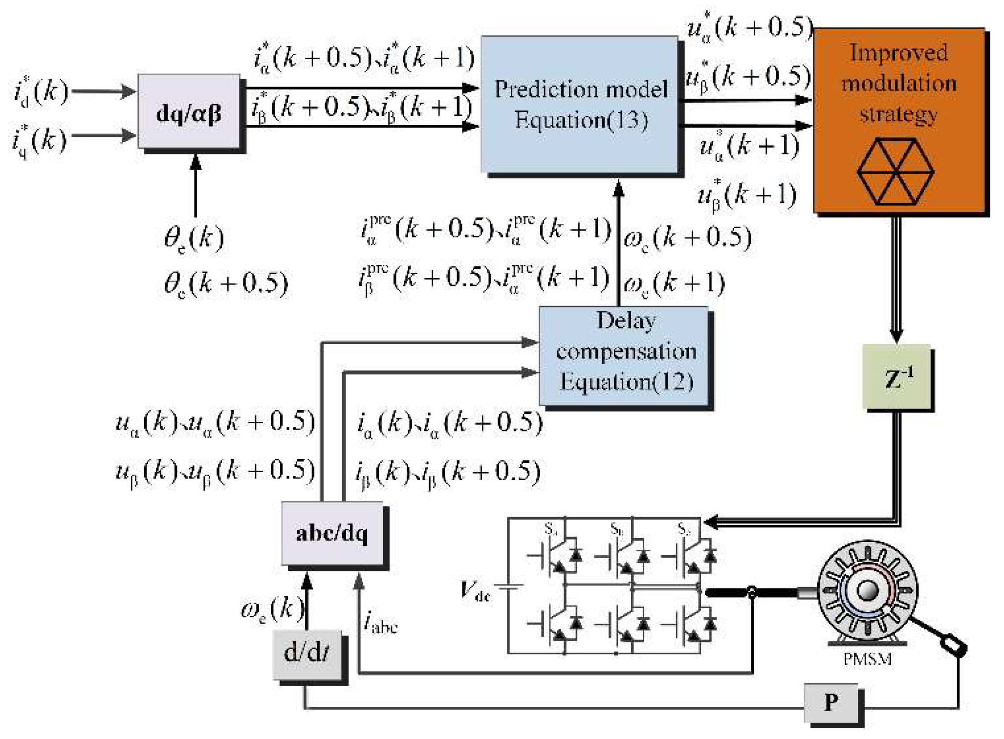
The various switching frequency deadbeat predictive current control strategy in this paper is shown in Figure 8.
Within a carrier cycle, information such as stator current and rotor angle was sampled once at Tk moment, and the duty ratio is updated once; sampling once at Tk+0.5 moment, and the duty ratio was updated once. That is the double sampling and double updating control strategy. Combined with the proposed clamping modulation strategy, the dynamic and steady performance of the motor system was improved, and the output current fluctuation was reduced on the premise that the switching frequency was not increased.

4. Simulation and Experimental Results

4.1. Simulation Results

In this section, the proposed improved deadbeat predictive current control strategy is simulated and analyzed on Matlab/Simulink. The parameters of SPMSM are shown in Table 1.
In order to verify the effectiveness of the improved prediction model in Section 3.1, the prediction model was simulated at 8000 r/min, as shown in Figure 9 and Figure 10 for the simulation results when the motor is running at 8000 r/min, and it was found that id and iq show a large tracking error when the traditional prediction model is used for the simulation. It can be found that the id and iq tracking accuracy is improved when the prediction model proposed in this paper is used. The effectiveness of the improved prediction model proposed in this paper was verified.
In order to verify the effectiveness of the improved modulation strategy proposed in Section 3.2, the simulation of the improved modulation strategy was verified at 13,000 r/min, as shown in Figure 11. It is worth noting that since the effectiveness of the improved prediction model has been verified in the previous simulation, the improved prediction model is still used in this set of simulations. From the analysis of the simulation results, it is clear that the current waveform is more sinusoidal with the improved modulation strategy.

4.2. Experimantal Results

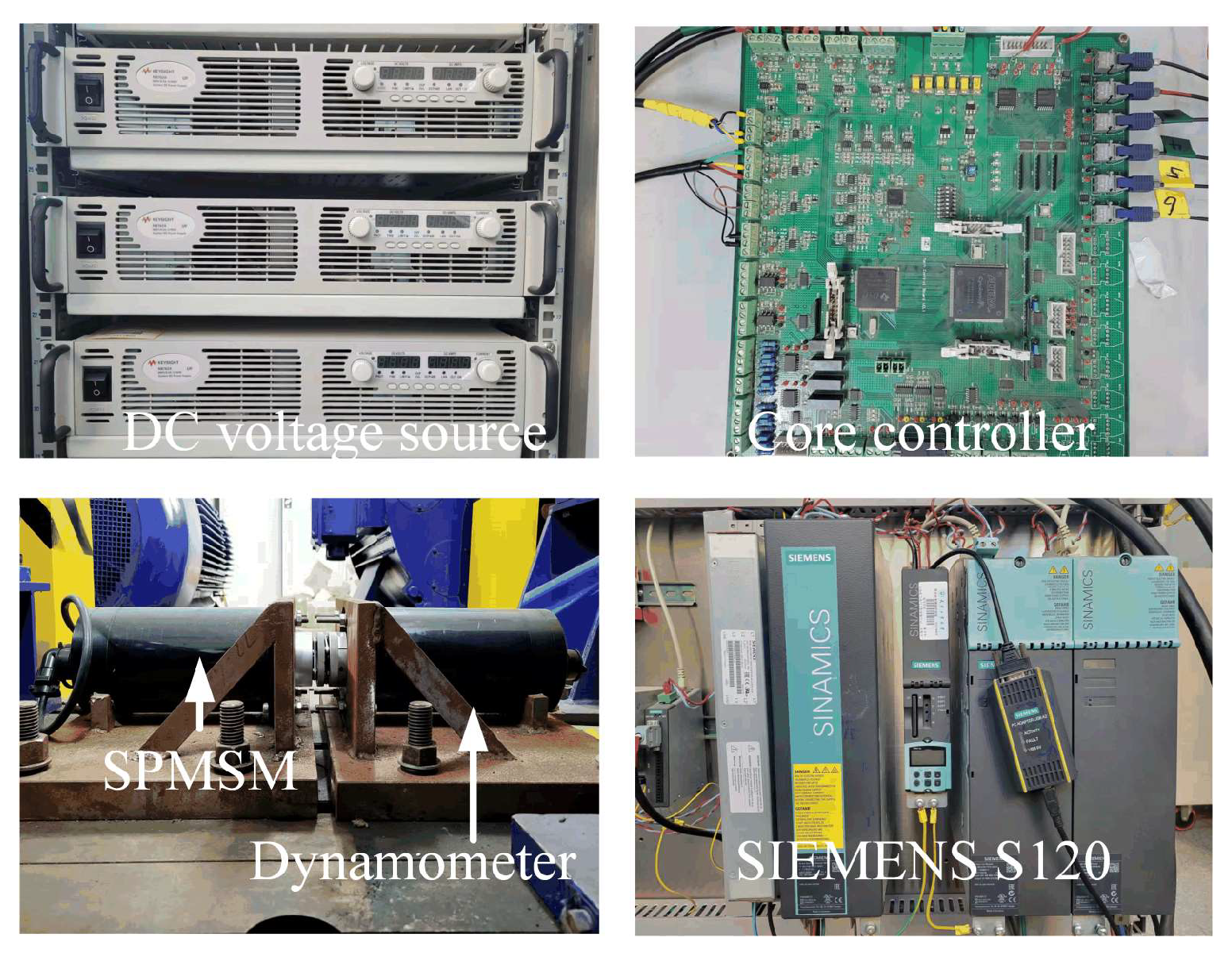
To verify the validity of the above theoretical analysis a complete set of experimental platforms was built, as shown in Figure 12.
In the experimental system, the control unit is TMS320F28335. The carrier frequency of the control system is set at 5 kHz, and the control cycle is 100 μs. The load motor is controlled by a Siemens S120 frequency converter and is coaxially connected to the experimental motor. The experimental motor parameters are shown in Table 1.
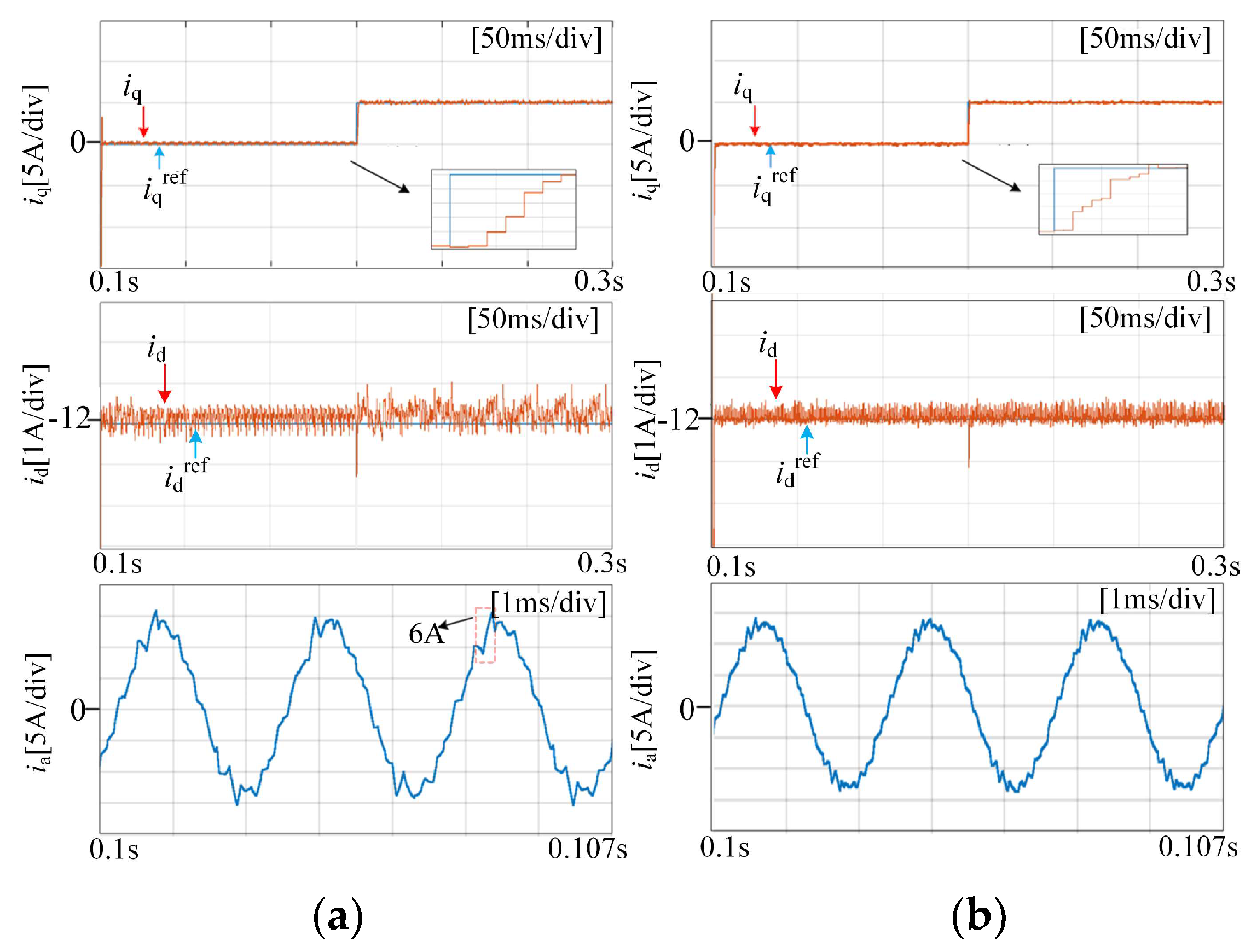
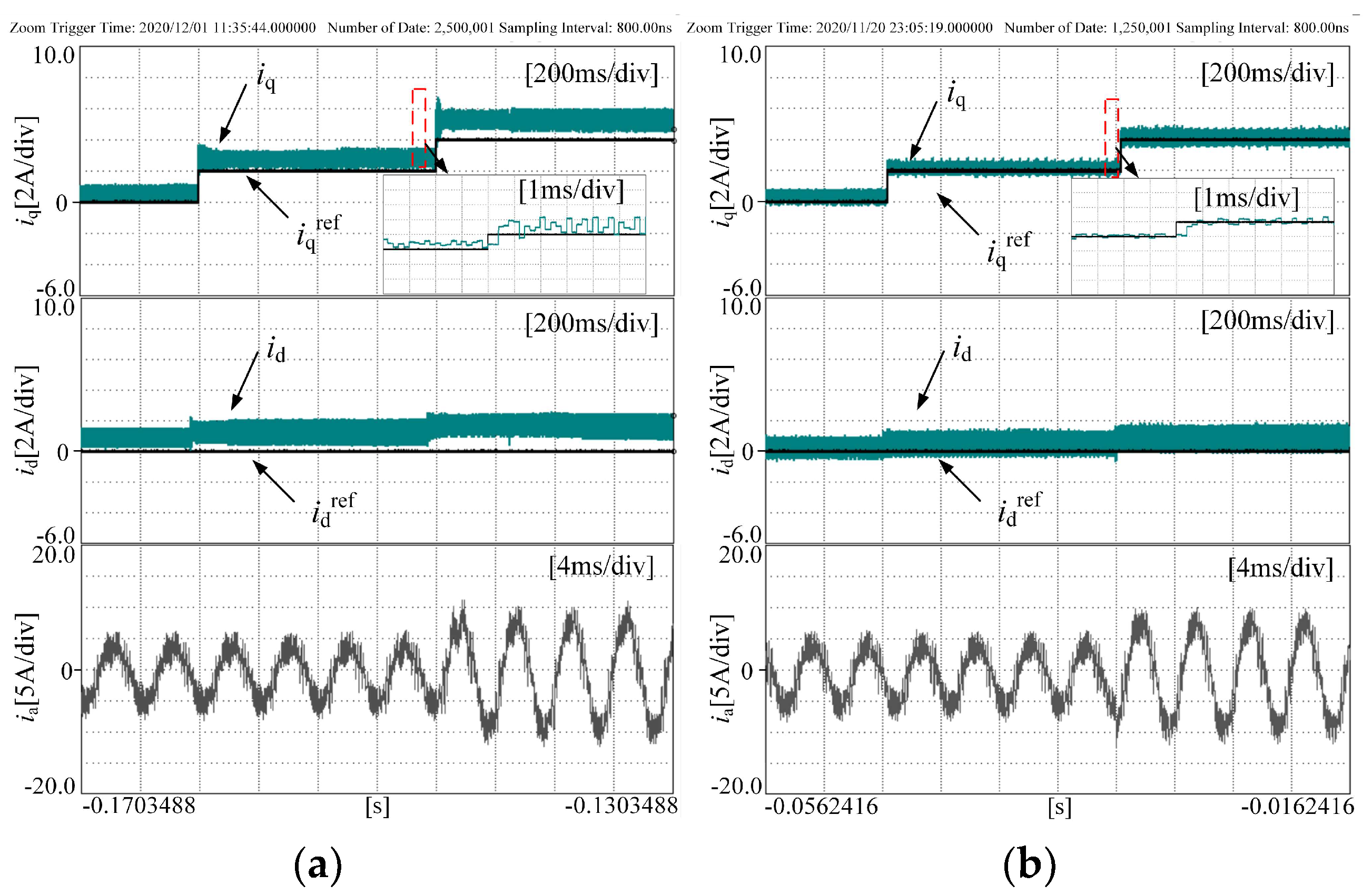
Figure 13 shows the experimental results when the motor runs at 8000 r/min and the carrier ratio is 18. The carrier ratio was calculated according to the ratio between the carrier frequency and motor operating frequency corresponding to the traditional fixed switching frequency predictive current control strategy. It is worth noting that the traditional PWM modulation strategy was used in both experiments. By comparing the current waveform in Figure 13, it can be seen that using the traditional prediction model for this experiment, when iq steps from 0A to 2A, the d-q axis current starts to show tracking errors, and there is a tracking error of about 1A between iq and iqref, as when iq changes to 4A, the error between iq and iqref increases, and there is a tracking error of about 1.4A. Meanwhile, the tracking error of id increases with the increase of iq. However, iq can always track iqref when using the improved prediction model considering the change of rotor position angle, and the id basically has no tracking error. The reason for the above experimental results is that when the carrier ratio is reduced, the traditional prediction model obtained by the approximation cannot meet the accuracy required by the model under this working condition. Meanwhile, the current harmonic content is increased under the low carrier ratio condition, which also amplifies the tracking error of the d-q axis current. The improved prediction model established in this paper fully considers the error of the prediction model under low carrier ratio conditions.
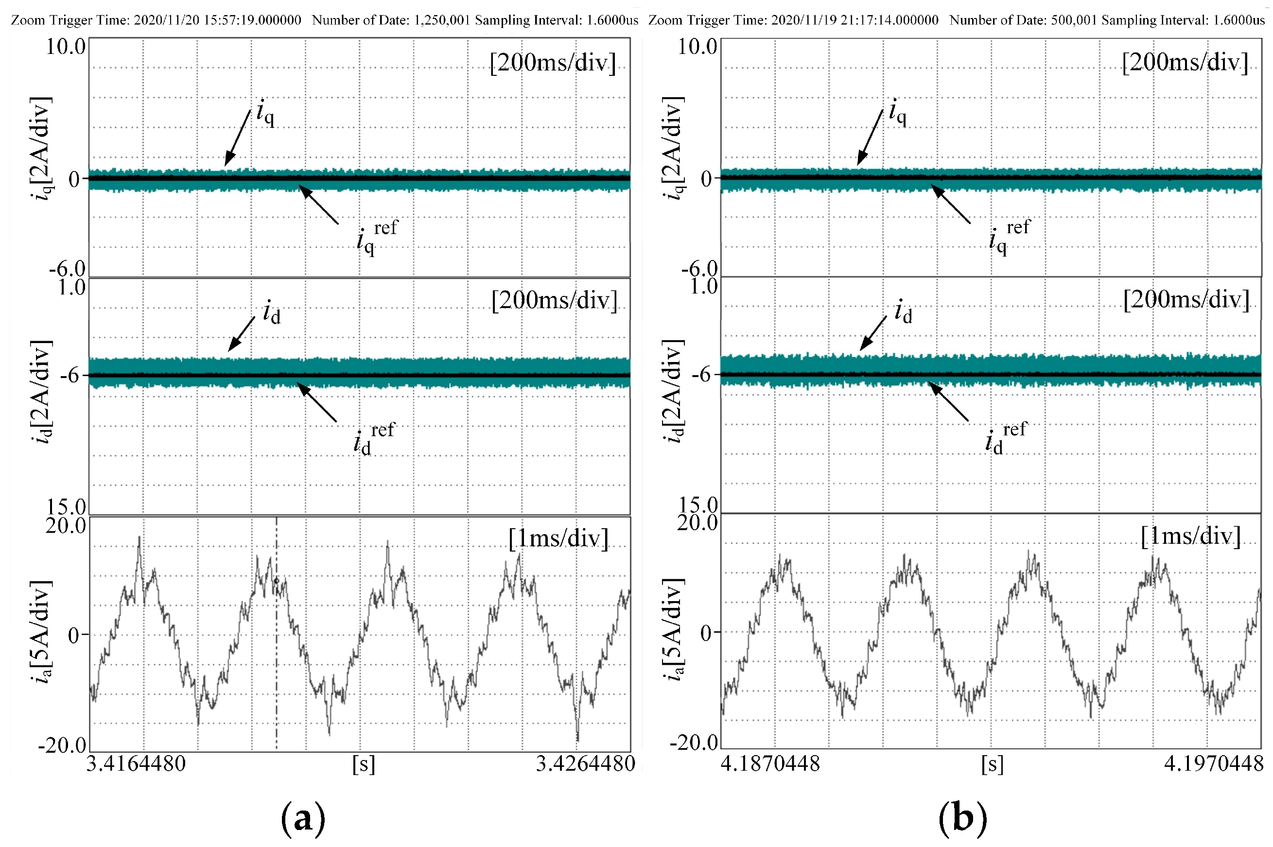
Figure 14 shows the waveforms of id, iq, and ia when the motor is running at 8000 r/min. At this time, since the advantages of the improved prediction model proposed in this paper have been proved by the experiment in Figure 13, the improved prediction model was adopted in subsequent experiments. By comparing the current waveforms in Figure 14a,b, it can be seen that the id and iq can track the reference value well. Therefore, the improved modulation strategy added to the control algorithm does not affect the current control.
In order to get the difference of phase current more directly, the FFT analysis was compared, as shown in Figure 15. The current distortion rate is significantly smaller with the effect of the improved modulation strategy.
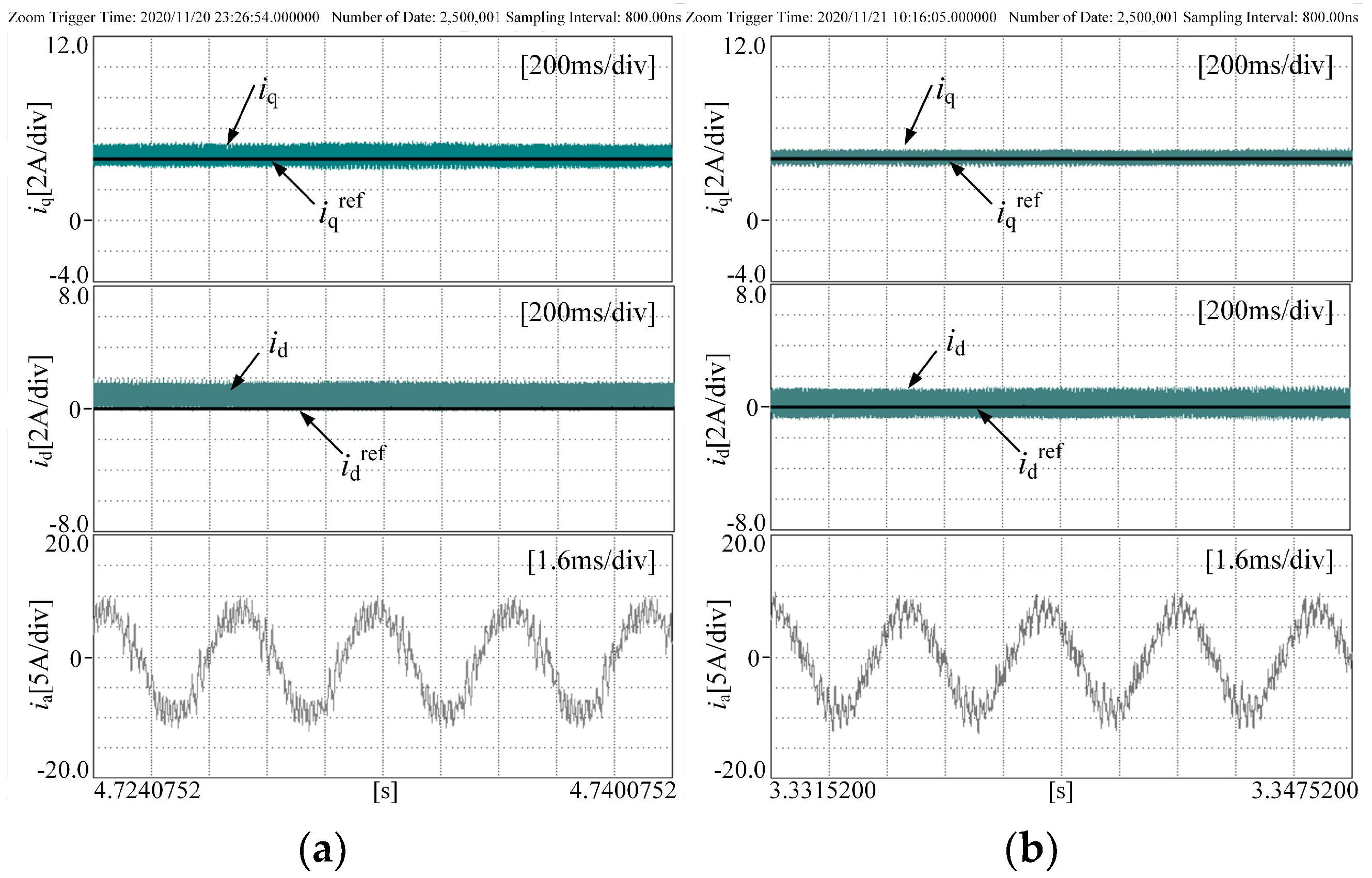
Figure 16 shows the experimental results of the carrier ratio of 11 at the speed of 13,000 r/min. At this time, since the advantages of the improved prediction model proposed in this paper have been proved by the experiment in Figure 13, the improved prediction model was adopted in subsequent experiments. In Figure 16, the improved prediction model for the low carrier ratio proposed in this paper is adopted, while in Figure 16a, the traditional SVPWM modulation strategy is adopted. It can be seen that when the motor is running at a low carrier ratio condition, the d-q axis current in Figure 16 can also track the current reference value well, but the peak value of the A phase current fluctuates about 2A, and the sinusoidal current waveform is poor. Figure 16b shows the results of adopting the proposed clamping modulation strategy. It is obvious that the fluctuation at the peak of the A phase current is significantly reduced, and the current waveform is more sinusoidal, which proves the effectiveness of the improved clamping modulation strategy proposed in this paper under the condition of high speed and low carrier ratio conditions.
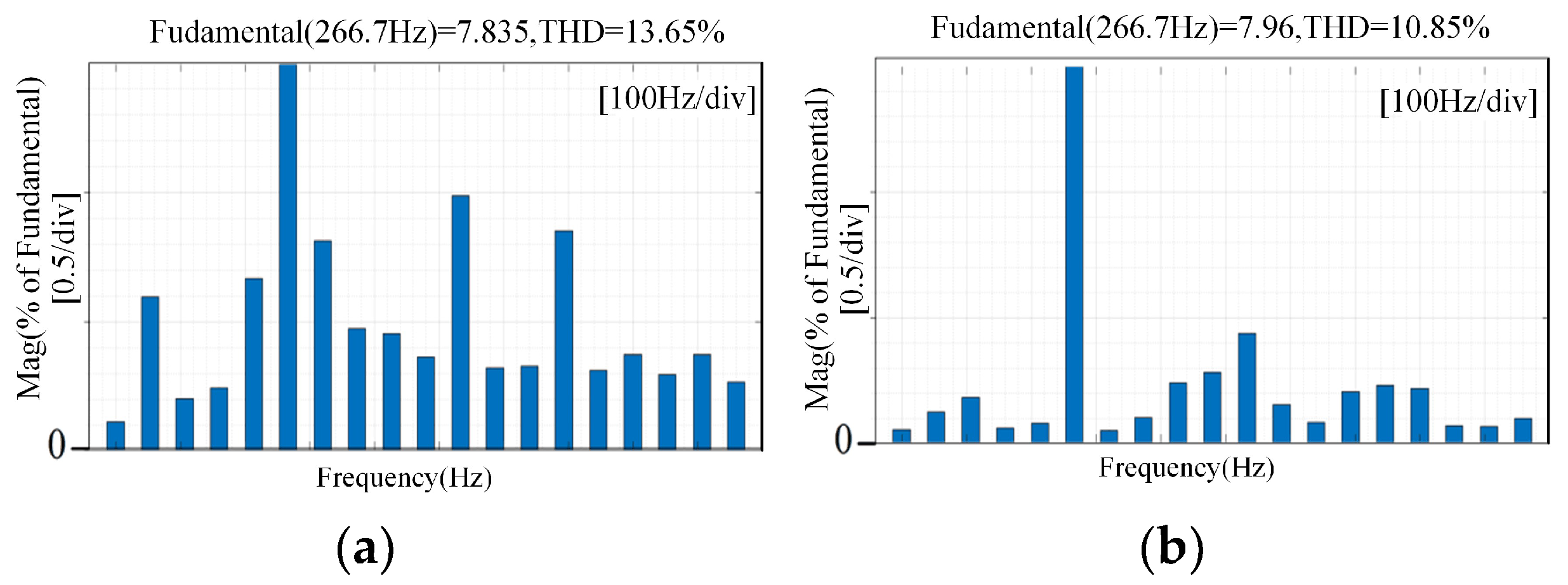
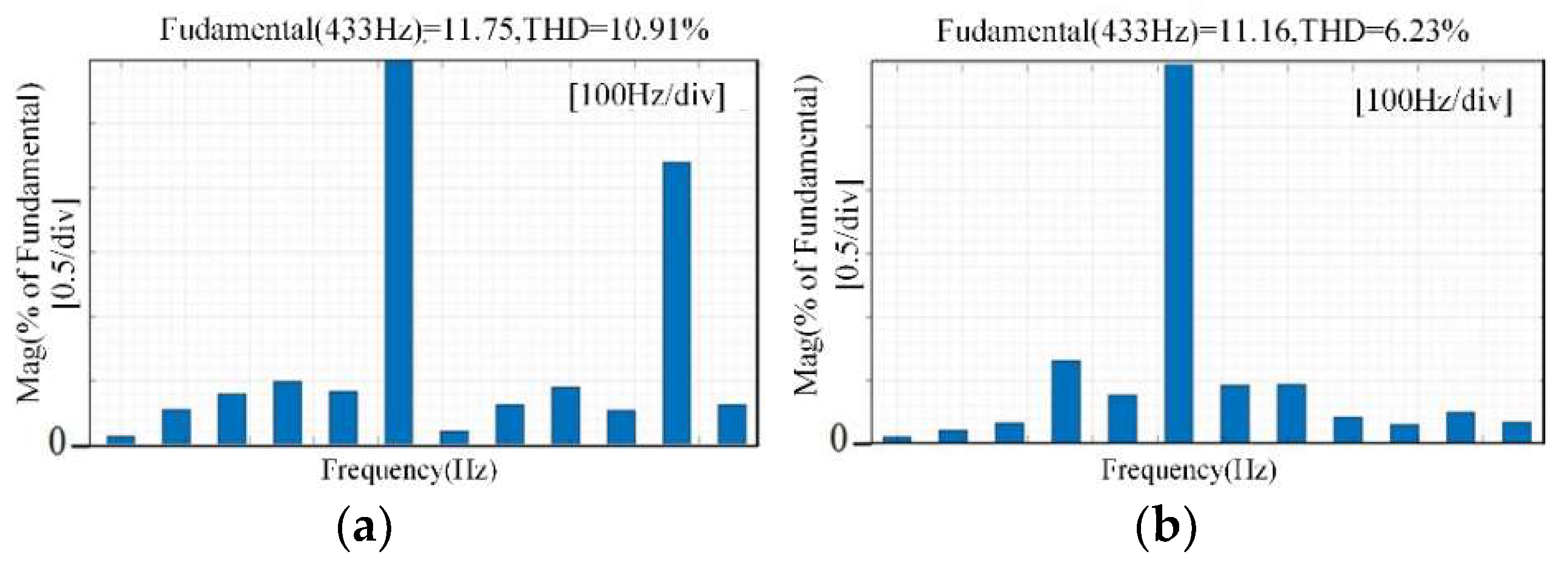
In order to observe the difference in current distortion rate more directly, the FFT analysis of phase current in Figure 16 and the current THD comparison are shown in Figure 17. The improved clamping modulation strategy proposed in this paper is obviously superior under the condition of high speed and low carrier ratio, which is consistent with theoretical analysis.
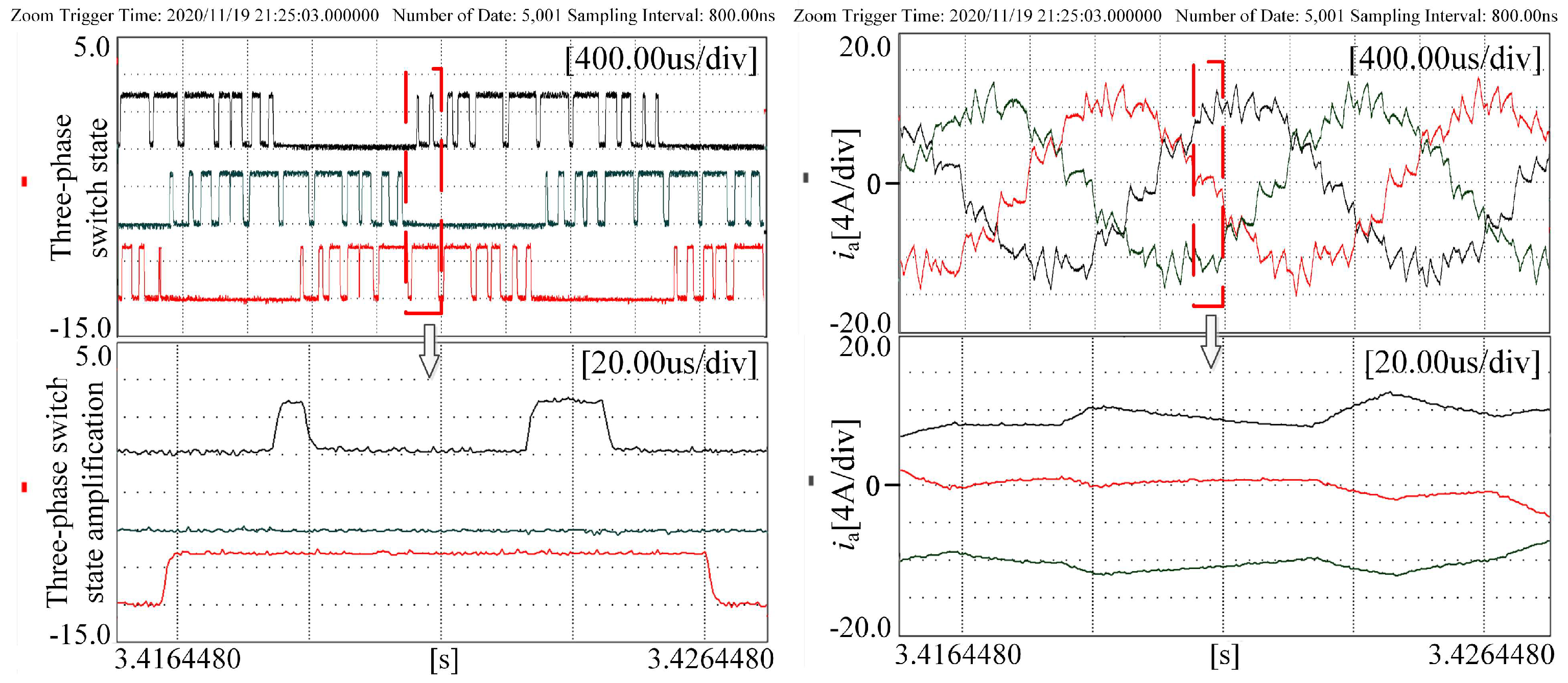
Figure 18 shows the inverter’s three-phase switching state and three-phase current waveform and an enlarged diagram corresponding to Figure 16b. It can be seen from Figure 18 that the switching state of the power devices changes compared with the traditional SVPWM modulation strategy, and the splitting of the intermediate effective vector is realized in the one-phase switching clamping state without increasing the switching frequency. That is, the switching action is still six times in the unit carrier cycle, which is the same as the switching cation times in the unit carrier cycle in the traditional SVPWM modulation strategy. However, from the point of view of the unit stator current cycle, the three-phase switching state rotation clamping is achieved, and the variable switching frequency control of the power devices is realized, which is consistent with the theoretical analysis. In addition, under the improved PWM modulation strategy, the switching time within the first and second half carrier cycles is not equal, which is the result of the more accurate synthesized voltage vector and duty ratio. The improved clamping modulation strategy proposed in this paper can improve the current waveform when the motor is running at high speed and low carrier ratio conditions, reduce the current fluctuation without increasing the switching frequency, and optimize the quality of the motor current.

5. Conclusions

Based on the analysis of the phenomenon that the dynamic and steady-state performance of permanent magnet synchronous motor decreases when it runs at high speed and low carrier conditions, this paper proposes a variable switching frequency deadbeat predictive current control strategy. The main conclusions are as follows.
Firstly, the error causes of the traditional prediction model in high speed and low carrier ratio operation were analyzed, and the prediction model suitable for low carrier ratio conditions was established on the α-β axis. Because the nonlinear change of the back EMF is considered in this model, the proposed prediction model has higher stability when the motor is running at high speed and low carrier ratio conditions. Secondly, the current fluctuation and harmonics are large in the case of the low carrier ratio with the traditional deadbeat predictive current control with the traditional modulation strategy. In this paper, by introducing clamping mode and adjusting the switch sequence, a variable switching frequency deadbeat predictive current control strategy was proposed.
The proposed method was compared with existing methods to derive a simple and effective prediction model that was applicable to high speed and low carrier ratio conditions. Then, the current harmonics during the motor operation under the improved model are analyzed and an improved modulation strategy were proposed to reduce the current harmonics at high speed and low carrier ratio conditions. The improved modulation strategy proposed in the paper is simple and effective, which can reduce the current harmonics while retaining the advantage of high dynamic response. Under the high speed and low carrier ratio condition, the proposed method not only ensures the current tracking accuracy and dynamic performance but also improves the current quality. The improved method is suitable for different motor types for current harmonic reduction at high speed and low carrier ratio conditions, which provides a good current control method.

Author Contributions

Conceptualization, Z.W. and C.W.; methodology, Z.W. and H.L.; software, C.W.; validation, C.W.; formal analysis, Z.W. and G.Z.; investigation, C.W.; resources, Z.W.; data curation, Z.H.; writing—original draft preparation, C.W.; writing—review and editing, X.J. and G.Z.; visualization, C.W.; supervision, H.L.; project administration, Z.W.; funding acquisition, Z.W. All authors have read and agreed to the published version of the manuscript.

Funding

This research was funded by “The National Natural Science Foundation of China, grant number 51977150”.

Data Availability Statement

Not applicable.

Conflicts of Interest

The authors declare no conflict of interest.

References

  1. Lunardi, A.; Conde, D.E.R.; de Assis, J.; Fernandes, D.A. Model Predictive Control with Modulator Applied to Grid Inverter under Voltage Distorted. Energies 2021, 14, 4953. [Google Scholar] [CrossRef]
  2. Fang, S.; Meng, J.; Wang, W.; Meng, Y.; Wang, Y.; Huang, D. Compensation Strategy of PMSM Predictive Control with Reduced Parameter Disturbance. Sustainability 2022, 14, 9868. [Google Scholar] [CrossRef]
  3. Jo, G.-J.; Choi, J.-W. Gopinath Model-Based Voltage Model Flux Observer Design for Field-Oriented Control of Induction Motor. IEEE Trans. Power Electron. 2019, 34, 4581–4592. [Google Scholar] [CrossRef]
  4. Cai, X.; Zhang, Z.; Wang, J.; Kennel, R. Optimal Control Solutions for PMSM Drives: A Comparison Study With Experimental Assessments. IEEE J. Emerg. Sel. Top. Power Electron. 2018, 6, 352–362. [Google Scholar] [CrossRef]
  5. Shi, T.; Zhang, W.; Xiao, M.; Geng, Q.; Xia, C.L. Predictive Current Control for Permanent Magnet Synchronous Motor Based on Operating Time of Vector. Trans. China Electrotech. Soc. 2017, 32, 1–10. [Google Scholar]
  6. Xu, C.; Han, Z.; Lu, S. Deadbeat Predictive Current Control for Permanent Magnet Synchronous Machines With Closed-Form Error Compensation. IEEE Trans. Power Electron. 2020, 35, 5018–5030. [Google Scholar] [CrossRef]
  7. Wang, H.; Xu, D.; Yang, M.; Li, N. Improved Deadbeat Predictive Current Control Strategy of Permanent Magnet Motor Drives. In Proceedings of the 2011 6th IEEE Conference on Industrial Electronics and Applications, Beijing, China, 21–23 June 2011; Volume 26, pp. 39–45. [Google Scholar]
  8. Zhang, X.; Hou, B.; Mei, Y. Deadbeat Predictive Current Control of Permanent-Magnet Synchronous Motors with Stator Current and Disturbance Observer. IEEE Trans. Power Electron. 2017, 32, 3818–3834. [Google Scholar] [CrossRef]
  9. Walz, S.; Lazar, R.; Buticchi, G.; Liserre, M. Dahlin-Based Fast and Robust Current Control of a PMSM in Case of Low Carrier Ratio. IEEE Access 2019, 7, 102199–102208. [Google Scholar] [CrossRef]
  10. Zhang, Z.; Jing, L.; Zhao, Y.; Wu, X.; Yang, J.; Wang, J. Decoupling Control of Permanent Magnet Synchronous Motor at High Speed and Low Switching Frequency. Proc. CSEE 2020, 40, 6345–6354. [Google Scholar]
  11. Cortes, P.; Rodriguez, J.; Silva, C.; Flores, A. Delay Compensation in Model Predictive Current Control of a Three-Phase Inverter. IEEE Trans. Ind. Electron. 2012, 59, 1323–1325. [Google Scholar] [CrossRef]
  12. Yu, A.; Wang, S.; Zhang, C.; Chai, X.; Kan, Z. Design of Digital Current Regulator for PMSM with Low Carrier Ratio. In Proceedings of the 2019 22nd International Conference on Electrical Machines and Systems (ICEMS), Harbin, China, 11–14 August 2019. [Google Scholar]
  13. Guo, J.; Fan, T.; Zhang, H. Stability Analysis of Permanent Magnet Synchronous Motor Current Loop Control at High Speed and Low Carrier Ratio. Proc. CSEE 2019, 39, 7336–7346. [Google Scholar]
  14. Hoffmann, N.; Fuchs, F.W.; Kazmierkowski, M.P.; Schröder, D. Digital current control in a rotating reference frame-Part l: System modeling and the discrete time-domain current controller with improved decoupling capabilities. IEEE Trans. Power Electron. 2016, 31, 5290–5305. [Google Scholar] [CrossRef]
  15. Jarzebowicz, L. Errors of a Linear Current Approximation in High-Speed PMSM Drives. IEEE Trans. Power Electron. 2017, 32, 8254–8257. [Google Scholar] [CrossRef]
  16. Jarzebowicz, L.; Mirchevski, S. Modeling the impact of rotor movement on non-linearity of motor currents waveforms in high-speed PMSM driver. In Proceedings of the 2017 19th European Conference on Power Electronics and Applications, Warsaw, Poland, 11–14 September 2017; pp. 1–8. [Google Scholar]
  17. Pei, G.; Liu, J.; Gao, X.; Tian, W.; Li, L.; Kennel, R. Deadbeat Predictive Current Control for SPMSM at Low Switching Frequency With Moving Horizon Estimator. IEEE J. Emerg. Sel. Top. Power Electron. 2021, 9, 345–353. [Google Scholar] [CrossRef]
  18. Sun, J.; Wang, Z.; Gu, X.; Xia, C. Predictive Current Control of PMSM with High Speed and Low frequency ratio. Proc. CSEE 2020, 40, 3663–3673. [Google Scholar]
  19. Liang, Y.; Liang, D.; Jia, S.; Chu, S.; He, J. A Full-Speed Range Hybrid PWM Strategy for High-Speed Permanent Magnet Synchronous Machine Considering Mitigation of Current Harmonics. In Proceedings of the 2019 IEEE Energy Conversion Congress and Exposition (ECCE), Baltimore, MD, USA, 29 September–3 October 2019; pp. 1886–1890. [Google Scholar] [CrossRef]
  20. Wang, H.; Liu, S.; Wu, S.; Guo, L.; Shi, T. Optimal Design of Permanent Magnet Structure to Reduce Unbalanced Magnetic Pull in Sur-face-Mounted Permanent-Magnet Motors. IEEE Access 2020, 8, 77811–77819. [Google Scholar] [CrossRef]
  21. Gao, J.; Gong, C.; Li, W.; Liu, J. Novel Compensation Strategy for Calculation Delay of Finite Control Set Model Predictive Current Control in PMSM. IEEE Trans. Ind. Electron. 2020, 67, 5816–5819. [Google Scholar] [CrossRef]
  22. Wang, Z.; Xie, S.; Jin, X.; Shi, T.; Yang, M. A novel deadbeat predictive current control of permanent magnet synchronous motor based on oversampling scheme. IET Power Electr. Appl. 2021, 15, 1029–1044. [Google Scholar] [CrossRef]
  23. Narayanan, G.; Krishnamurthy, H.K.; Zhao, D.; Ayyanar, R. Advanced bus-clamping PWM techniques based on space vector approach. IEEE Trans. Power Electron. 2006, 21, 974–984. [Google Scholar] [CrossRef]
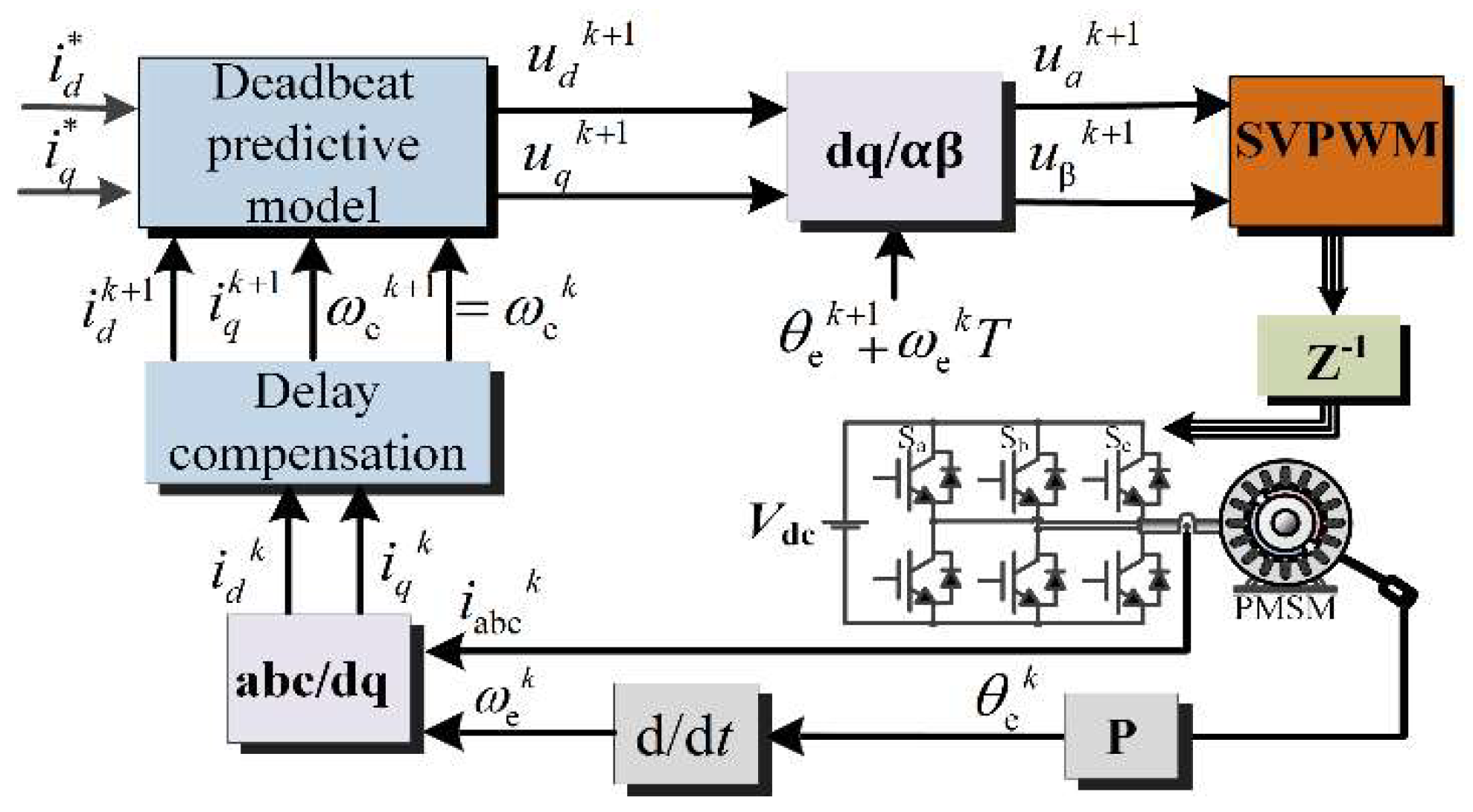
Figure 1. Block diagram of traditional deadbeat predictive current control.
Wevj 14 00064 g001
Figure 2. Traditional sampling and duty update timing.
Wevj 14 00064 g002
Figure 3. Schematic diagram of three-phase switching state and A-phase current fluctuation in sector II.
Wevj 14 00064 g003
Figure 4. Current fluctuation with different modulation.
Wevj 14 00064 g004
Figure 5. Current fluctuation under different carrier ratio.
Wevj 14 00064 g005
Figure 6. Splitting active vector three-phase switching state in dual-sample dual-update strategy.
Wevj 14 00064 g006
Figure 7. Comparison diagram of three-phase switching state and A-phase current fluctuation with different modulation strategy in sector II. (a) represents double-sampling and double-updating non-clamping modulation, (b) represents double-sampling and double-updating clamping modulation, and (c) represents the improved clamping modulation used in this paper.
Wevj 14 00064 g007
Figure 8. Block diagram of variable switching frequency deadbeat predictive current control.
Wevj 14 00064 g008
Figure 9. Traditional prediction model d-q axis current waveform at 8000 r/m.
Wevj 14 00064 g009
Figure 10. Improved prediction model d-q axis current waveform at 8000 r/m.
Wevj 14 00064 g010
Figure 11. d-q axis current and A-phase current waveform at 13,000 r/min. (a) represents traditional PWM modulation, (b) represents improved PWM modulation.
Wevj 14 00064 g011
Figure 12. Experimental platform.
Wevj 14 00064 g012
Figure 13. d-q axis current and A-phase current waveform at 8000 r/min and carrier ratio about 18. (a) represents traditional prediction model, (b) represents improved prediction model.
Wevj 14 00064 g013
Figure 14. d-q axis current and A-phase current waveform at 8000 r/min and carrier ratio about 18. (a) represents traditional PWM modulation, (b) represents improved PWM modulation.
Wevj 14 00064 g014
Figure 15. THD analysis of the phase current at 8000 r/min and carrier ratio about 18. (a) represents the current THD analysis of traditional PWM modulation, (b) represents current THD analysis of improved PWM modulation.
Wevj 14 00064 g015
Figure 16. d-q axis current and A-phase current waveform at 13,000 r/min and carrier ratio about 11. (a) represents traditional PWM modulation, (b) represents improved PWM modulation.
Wevj 14 00064 g016
Figure 17. THD analysis of the phase current at 13,000 r/min and carrier ratio about 11. (a) represents the current THD analysis of traditional PWM modulation, (b) represents the current THD analysis of improved PWM modulation.
Wevj 14 00064 g017
Figure 18. Three-phase switch state and current waveform on improved PWM modulation strategy at 13,000 r/min and carrier ratio at about 11.
Wevj 14 00064 g018
Table 1. Rated parameters of PMSM.
UN/VIN/APN/kWTN/N·mωN/r/minPnLs/mHRsψf/Wb
54019.33.711.8300023.20.380.145
Disclaimer/Publisher’s Note: The statements, opinions and data contained in all publications are solely those of the individual author(s) and contributor(s) and not of MDPI and/or the editor(s). MDPI and/or the editor(s) disclaim responsibility for any injury to people or property resulting from any ideas, methods, instructions or products referred to in the content.