Article

Topological Optimization of Vehicle ISD Suspension under Steering Braking Condition

1
School of Automotive and Traffic Engineering, Jiangsu University, Zhenjiang 212013, China
2
School of Mechanical Engineering, Beijing Institute of Technology, Beijing 100081, China
3
Chinese Scholartree Ridge Laboratory, China North Vehicle Research Institute, Beijing 100072, China
*
Author to whom correspondence should be addressed.
World Electr. Veh. J. 2023, 14(10), 297; https://doi.org/10.3390/wevj14100297
Submission received: 14 September 2023 / Revised: 9 October 2023 / Accepted: 16 October 2023 / Published: 18 October 2023
(This article belongs to the Special Issue Dynamics, Control and Simulation of Electrified Vehicles)

Abstract

:
Anti-roll and anti-pitch are important directions in the comprehensive research of automobiles. In order to improve the anti-roll and anti-pitch performance of the vehicle, an inerter was applied to the vehicle suspension system, and a 14 DOF vehicle nonlinear dynamics model was established. The influence of the change in inertance in the eight kinds of improved ISD (Inerter-Spring-Damper) suspension structures on the RMS (root mean square) value of performance indexes of roll, vertical, and pitch motion of the vehicle was studied. Based on this, the vehicle’s ISD structure with better performance was selected, and the NSGA-Ⅱ algorithm was adopted to optimize the selected structural parameters. The simulation results showed that the four kinds of suspension hadbetter comprehensive performance, and their structureswere, respectively, excluding the supporting spring in parallel, (1) an inerter in series with a spring and a damper in parallel, (2) a damper in series with a spring and an inerter in parallel, (3) an inerter and a damper in series, and (4) the damper in parallel with a spring and an inerter in series. The ISD suspension structure had better comprehensive performance under step steering braking, which was obviously better than the passive suspension, and effectively improved the vehicle ride comfort, anti-roll and anti-pitch performance. Under the hook steering braking, the lateral load transfer rate was used to evaluate the vehicle’s anti-rollover ability. The results showed that the ride comfort and anti-rollover ability of ISD suspension were better than those of passive suspension. Under the condition of taking into account the anti-pitching ability, the suspension consists of a supporting spring in parallel with an inerter, and a damper in series was better.

1. Introduction

The suspension system is an important part of the vehicle chassis, which affects the stability of the vehicle together with the steering and braking systems [1]. Under extreme driving conditions such as high-speed obstacle avoidance and low-adhesion road steering, vehicles are prone to excessive roll or rollover [2]. In urban working conditions with frequent braking, the car body will produce pitch vibration under the influence of braking control strategy and suspension parameters, causing discomfort [3,4,5]. In recent years, many scholars have devoted themselves to improving the anti-rollover stability of vehicles, mainly via drive-by-wire steering [6], drive-by-wire control, active suspension [7], and lateral stabilizer bars [8]. The research on improving the anti-pitch stability of vehicles mainly focuses on braking and active suspension control [9,10].
In order to determine the optimal suspension parameters to improve the roll and pitch stability of vehicles, intelligent optimization algorithms are generally used to find the optimization. At present, the commonly used intelligent optimization algorithms include genetic algorithms, particle swarm algorithms, ant colony algorithms, simulated annealing algorithms, and so on. Hualing Bi [11] improved the searchability of the genetic algorithm by introducing the tabu mechanism into the genetic algorithm. Heng Wen [12] proposed a global optimal group search optimization algorithm to improve the performance of the algorithm by reducing the update times of redundant solutions.

2. Literature Review

To improve anti-roll and anti-pitch stability, Li Shengqin [13] proposed a layered integrated control strategy for active suspension and differential braking, and the simulation results showed that the strategy enhanced the anti-rollover stability of the bus. Zhao Shuen [14] used nonlinear control and fuzzy control to conduct performance research and designed a multi-level coordinated control system based on multi-level hierarchical control theory. The anti-lock braking system, semi-active suspension system, and active front-wheel steering were combined to improve the driving stability of the vehicle. Chen Long [15] established the lateral dynamics model and the air suspension nonlinear model and carried out the saddle knot bifurcation analysis on the anti-roll stability of vehicles under special driving conditions. Huang Kuankai [16] established a dynamic model of hydraulic interconnected inertial suspension, and the simulation structure showed that the hydraulic interconnected inerter had significantly improved the anti-roll and anti-pitch ability of the vehicle, compared with the lateral stabilizer bar and the ordinary hydraulic interconnected suspension. Lu Shaobo [17] designed a collaborative control strategy of a braking system controlled by integral sliding mode and a suspension system controlled by grey mode fuzzy, which improved the anti-roll performance of vehicles compared with a single control strategy. At present, many scholars have conducted a lot of research on the use of suspension systems to improve the anti-roll and anti-pitch stability of vehicles, but the suspension structure is still limited to the traditional “spring-damper” structure and rarely considered from the new suspension configuration.
Smith [18] proposed an inertial component called the “inerter”, which can effectively replace the role of mass blocks in vibration isolation performance. By generating inertial force instead of a mass block, the inerter breaks through the limit of “grounding” of one endpoint of the mass block, which is also convenient for application in a vibration isolation system. The inertial force is a linear expression of the relative acceleration of the two endpoints, expressed as F = b (a2 − a1), where a2 and a1 are the acceleration of the two endpoints, and b is the inertance of the inerter. Together with the spring and damping, it forms the ISD suspension system. At present, vehicles’ passive ISD suspension have been proven to be capable of effectively improving the ride performance of vehicles [19,20], but there are few studies on the application of the inerter to improve the anti-roll performance of vehicles [21]. It can be seen that the inerter has great potential in improving the anti-roll performance of vehicles. Shen Yujie solves the problem of low-frequency and high-frequency vibration suppression of vehicles by designing a passive fractional order electrical network [22] and PDD-based active control design of electromechanical ISD suspension [23]. Literature [21] selected passive suspension, the suspension of a damper and an inerter in parallel, the suspension of a damper and an inerter in series, and three-element suspension based on the dynamic vibration absorption principle (all supporting springs in parallel) built a seven-degree of freedom vehicle model and analyzed the influence of four suspension structures on vehicle roll. On this basis, a 14-degree-of-freedom model considering wheel nonlinearity is established, and a vehicle acceleration braking model is added. The influence of ISD suspension structure on vehicle pitch motion is studied. According to the research results of the literature [21], the improved three-element topological inertial suspension structure with a supporting spring in parallel is helpful in improving the roll stability of the vehicle. Therefore, this paper comprehensively considers eight kinds of improved three-element topological suspension structures with supporting springs in parallel, adds braking conditions, and analyzes their comprehensive influence on the pitch stability, roll stability, and vertical stability of the vehicle.
Therefore, by building a 14-degree-of-freedom nonlinear dynamic model of the vehicle and taking the improved three-element ISD suspension as the research object, this paper studied the influence of the inertance of the ISD suspension structure on the ride comfort, anti-roll performance, and anti-pitch performance of the vehicle via simulation analysis under the same braking effect. On this basis, the optimal structure is selected for parameter optimization, and the simulation analysis is carried out.

3. Construction of Vehicle Nonlinear Dynamics Model

3.1. Vehicle Dynamics Model

On the basis of considering the nonlinear dynamics characteristics of the vehicle, the constructed model is simplified:
(1)
Ignore the impact of air resistance and rolling resistance on the car;
(2)
Ignore the influence of the steering system and assume that the left and right front wheel angles are the same as the input variables;
(3)
Assume that the center of gravity of the car coincides with the origin of the moving coordinate system when the car is driving;
(4)
Assume that the four tires have the same characteristics.
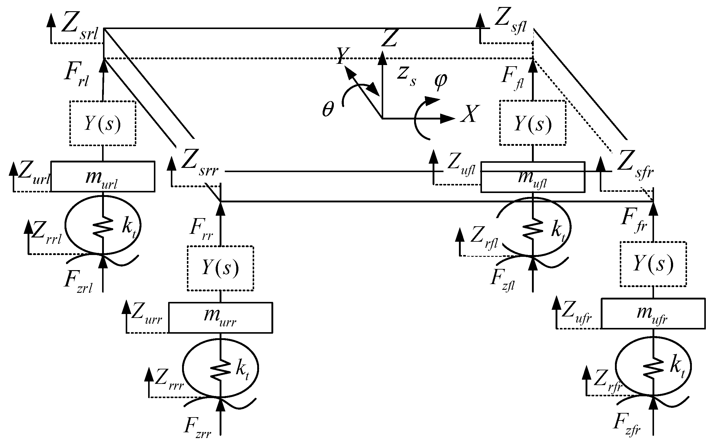
Figure 1 and Figure 2 are 14 DOF vehicle nonlinear models, including longitudinal, lateral, vertical, yaw, pitch, roll motion of the vehicle body, vertical jitter of four wheels, and rolling around the center [24].
The vertical motion of the body is as follows:
m s z ¨ s = F f l + F f r + F r l + F r r
The body roll motion is as follows:
I x φ ¨ = m t ( v ˙ + u ψ ˙ ) h 2 + m s g h 1 sin ( φ ) + ( F f l F f r ) w f 2 + ( F r l F r r ) w r 2
The pitch motion of the body is as follows:
I y θ ¨ = m t ( u ˙ v ψ ˙ ) h 3 + m s g h 1 sin ( θ ) + l r ( F r l + F r r ) l f ( F f l + F f r )
The yaw motion of the vehicle is as follows:
I z ψ ¨ = l f [ ( F y f l + F y f r ) cos ( δ ) + ( F x f l + F x f r ) sin ( δ ) ] l r ( F y r l + F y r r ) + w f 2 [ ( F x f r F x f l ) cos ( δ ) + ( F y f l F y f r ) sin ( δ ) ] + w r 2 ( F x r r F x r l ) + ( M z f l + M z f r + M z r l + M z r r )
The longitudinal motion of the vehicle is as follows:
m t ( u ˙ v ψ ˙ ) = ( F x f l + F x f r ) cos ( δ ) ( F y f l + F y f r ) sin ( δ ) + F x r l + F x r r
The lateral movement of the vehicle is as follows:
m t ( v ˙ + u ψ ˙ ) = ( F x f l + F x f r ) sin ( δ ) + ( F y f l + F y f r ) cos ( δ ) + F y r l + F y r r
The vertical displacement equation of the four corners of the car body is expressed as
Z s f l = z s l f θ + w f 2 φ Z s f r = z s l f θ w f 2 φ Z s r l = z s + l r θ + w r 2 φ Z s r r = z s + l r θ w r 2 φ
The movement of unsprung mass is as follows:
m u f l Z ¨ u f l = k t ( Z r f l Z u f l ) F f l m u f r Z ¨ u f r = k t ( Z r f r Z u f r ) F f r m u r l Z ¨ u r l = k t ( Z r r l Z u r l ) F r l m u r r Z ¨ u r r = k t ( Z r r r Z u r r ) F r r
The vehicle ISD suspension force equation is as follows:
F f l = Y ( s ) ( Z ˙ u f l Z ˙ s f l ) k 1 2 w f ( φ Z u f l Z s f l 2 w f ) F f r = Y ( s ) ( Z ˙ u f r Z ˙ s f r ) k 1 2 w f ( φ Z u f r Z s f r 2 w f ) F r l = Y ( s ) ( Z ˙ u r l Z ˙ s r l ) k 2 2 w r ( φ Z u r l Z s r l 2 w r ) F r r = Y ( s ) ( Z ˙ u r r Z ˙ s r r ) k 2 2 w r ( φ Z u r r Z s r r 2 w r )
Tire vertical load change is as follows:
F z f l = F f l + m u f l g + m s g l r 2 ( l r + l f ) F z f r = F f r + m u f r g + m s g l r 2 ( l r + l f ) F z r l = F r l + m u r l g + m s g l f 2 ( l r + l f ) F z r r = F r r + m u r r g + m s g l f 2 ( l r + l f )
In the above formula, m t represents the vehicle mass; m s indicates the sprung mass; m u f l , m u f r , m u r l , and m u r r are four wheel spring mass; I x , I y , and I z are the moment of inertia of vehicle body roll, pitch, and yaw, respectively; u denotes the lateral speed of the vehicle; v represents the lateral speed of the vehicle; ψ represents the yaw angle; θ represents the pitch angle; φ indicates the roll angle; δ represents the front wheel steering angle; Y ( s ) is the impedance expression of ISD suspension topology; k t denotes the radial stiffness of the tire; z s represents the vertical displacement of the body; Z s f l , Z s f r , Z s r l , and Z s r r represent the vertical displacement of the sprung mass at the four corners of the body; Z u f l , Z u f r , Z u r l , and Z u r r represent vertical displacement of unsprung mass; Z r f l , Z r f r , Z r r l , and Z r r r represent road excitation; k 1 and k 2 represent the roll stiffness of front and rear suspension; l f and l r represent the distance from the center of mass to the front and rear wheels; w f and w r denote the front and rear wheel base; h 1 represents the distance between the body’s center of mass and the ground; h 2 indicates the distance from the roll center to the ground; h 3 represents the distance from the pitch center to the ground; F f l , F f r , F r l , and F r r indicate the vertical load of suspension; F z f l , F z f r , F z r l , and F z r r are the vertical supporting force of the ground facing the tire; F x f l , F x f r , F x r l , and F x r r indicate the longitudinal force of the tire; F y f l , F y f r , F y r l , and F y r r indicate tire lateral force; and M z f l , M z f r , M z r l , and M z r r indicate the tire righting torque.
The braking model is as follows:
I w ω f l = T b f l F x f l R w I w ω f r = T b f r F x f r R w I w ω r l = T b r l F x r l R w I w ω r r = T b r r F x r r R w
In the above formula, I w represents the moment of inertia of the tire rotating around the center; ω f l , ω f r , ω r l , and ω r r represent the angular speed at which the tire rotates around the center; T b f l , T b f r , T b r l , and T b r r denote wheel-braking torque; and R w represents the rolling radius of the wheel.

3.2. Tire Model

The tire model selects the widely used “magic tire formula” [25], whose mathematical expression is as follows:
Y ( x ) = D sin { C arctan [ B ( x + s h ) E ( B ( x + s h ) arctan ( B ( x + s h ) ) ) ] } + s v
In the above formula, D represents the peak factor; B represents the stiffness factor; E represents curve curvature factor; C represents curve shape factor; s v represents the vertical drift of the curve; and s h represents the horizontal drift of the curve.
The tire longitudinal force model is as follows:
F x 0 = D x sin { C x arctan [ B x ( λ + s h ) E x ( B x ( λ + s h ) arctan ( B x ( λ + s h ) ) ) ] }
In the above formula, λ denotes the longitudinal slip rate of the tire; and when pure braking, it is λ = u R w ω u .
The tire lateral force model is as follows:
F y 0 = D y sin { C y arctan [ B y ( α + s h ) E y ( B y ( α + s h ) arctan ( B y ( α + s h ) ) ) ] } + s v
In the above formula, α indicates the tire side deflection angle.
The mathematical expression of the four wheels is as follows:
α f l = arctan ( v + l f ψ ˙ u 0.5 w f ψ ˙ ) δ α f r = arctan ( v + l f ψ ˙ u ) δ α r l = arctan ( v l r ψ ˙ u 0.5 w r ψ ˙ ) α r r = arctan ( v l r ψ ˙ u )
The tire righting torque model is as follows:
M z = D z sin { C z arctan [ B z ( α + s h ) E z ( B z ( α + s h ) arctan ( B z ( α + s h ) ) ) ] } + s v
Under the combined conditions of steering and braking, the mathematical expressions of the corrected tire longitudinal force and lateral force are as follows:
F x = σ x σ F x 0
F y = σ y σ F y 0
In the above formula, σ = σ x 2 + σ y 2 ; σ x = λ 1 + λ ; σ y = tan α 1 + λ .

3.3. ISD Suspension Model

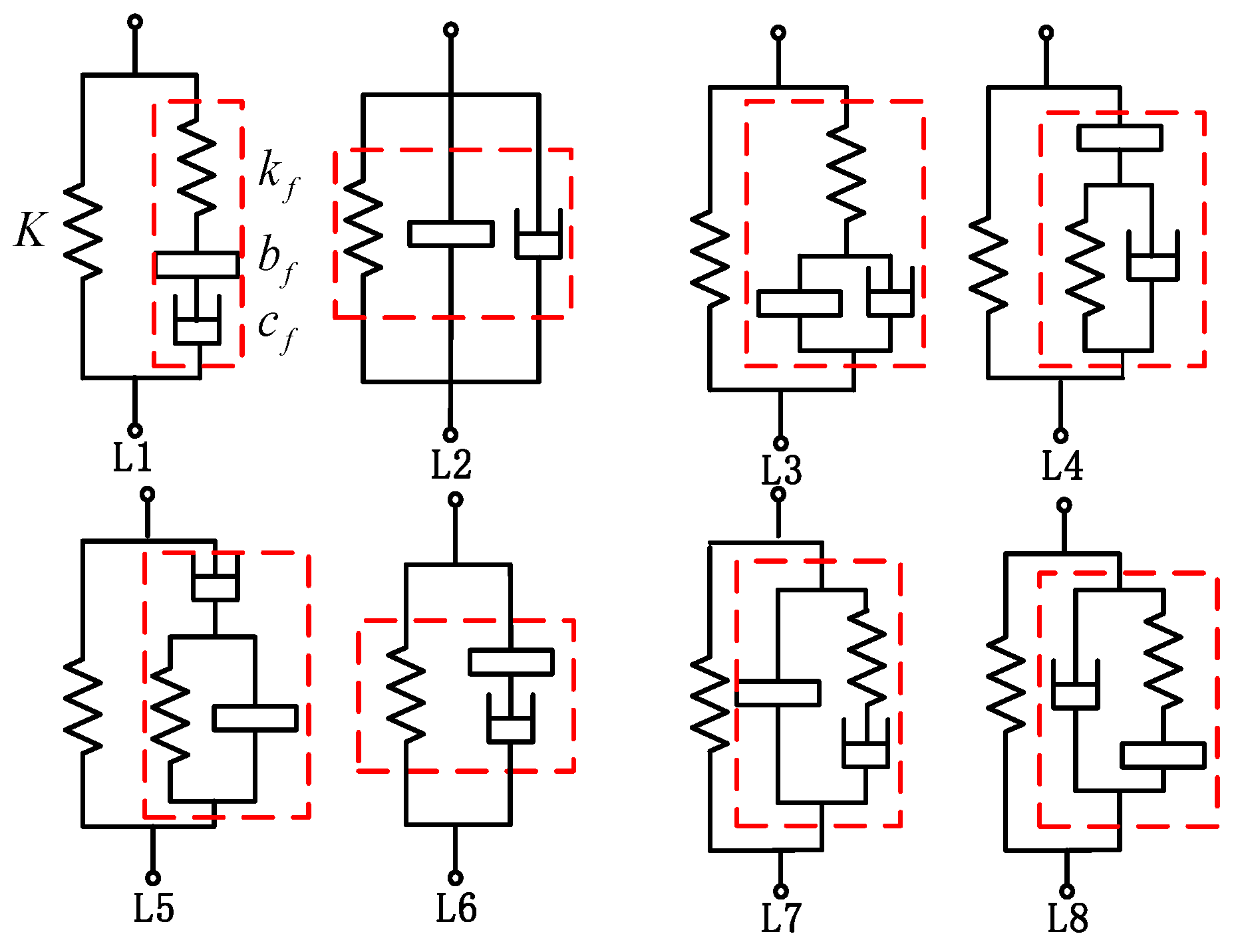
In this paper, eight improved three-component vehicle ISD suspensions [19] are adopted, and their structural diagram is shown in Figure 3. In addition to S2 and S6, a support spring is connected in parallel with the original three-element ISD topology to ensure suspension performance.
According to Figure 3, taking L1 as an example, the suspension structure of the left front wheel of the wheel is selected, where K is the supporting spring stiffness, k f is the auxiliary spring stiffness, b f is the inertance of the inerter, and c f is the damping coefficient. The impedance expressions of eight kinds of ISD suspension structures are presented, respectively.
The ISD suspension impedance expression of L1 topology is as follows:
Y 1 ( s ) = ( K + k f ) b f c f s 2 + K k f b f s + K k f c f b f c f s 3 + k f b f s 2 + k f c f s
The ISD suspension impedance expression of L2 topology is as follows:
Y 2 ( s ) = b f s 2 + c f s + K s
The ISD suspension impedance expression of L3 topology is as follows:
Y 3 ( s ) = b f ( K + k f ) s 2 + c f ( K + k f ) s + K k f b f s 3 + c f s 2 + k f s
The ISD suspension impedance expression of L4 topology is as follows:
Y 4 ( s ) = b f c f s 3 + b f ( K + k f ) s 2 + c f K s + K k f b f s 3 + c f s 2 + k f s
The ISD suspension impedance expression of L5 topology is as follows:
Y 5 ( s ) = b f c f s 3 + b f K s 2 + c f ( K + k f ) s + K k f b f s 3 + c f s 2 + k f s
The ISD suspension impedance expression of L6 topology is as follows:
Y 6 ( s ) = b f c f s 2 + b f K s + K c f b f s 2 + c f s
The ISD suspension impedance expression of L7 topology is as follows:
Y 7 ( s ) = b f c f s 3 + b f k f s 2 + c f ( K + k f ) s + K k f c f s 2 + k f s
The ISD suspension impedance expression of L8 topology is as follows:
Y 8 ( s ) = b f c f s 3 + b f ( K + k f ) s 2 + c f k f s + K k f b f s 3 + k f s

4. Action Law of ISD Suspension Topology

4.1. Pavement Input Model

Reference [26] on the single wheel pavement input model takes white noise as the excitation source of random pavement input, and its mathematical expression is as follows:
Z r ( t ) = 2 π f 0 Z r ( t ) + 2 π G 0 u w ( t )
In the above formula, Z r represents road excitation; w ( t ) is the Gaussian white noise with a mean of 0; f 0 represents the lower cut-off frequency, which is 0.01 Hz; and G 0 represents the roughness coefficient of the road surface. The value of the B-class road surface is 6.4 × 10 5 m3.
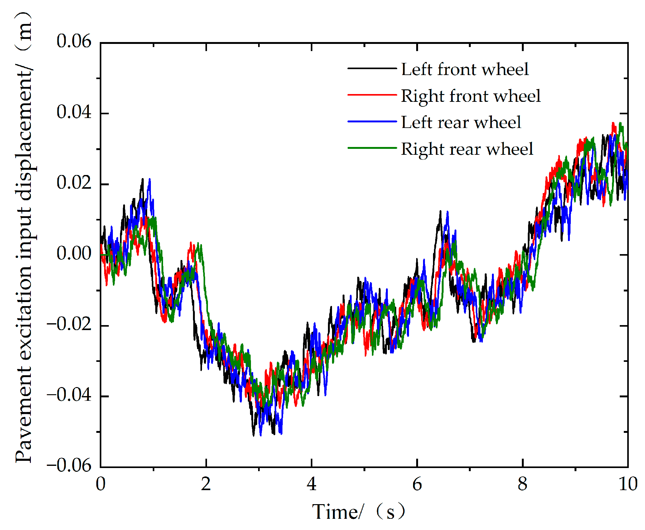
Assuming that the vehicle is driving in a straight line at the initial speed of 20 m/s, the road input of the front wheel and the rear wheel are the same, and the rear wheel will have a wheelbase/speed lag relative to the front wheel. The road excitation at the left and right wheels is strongly correlated at low frequency and weakly correlated at high frequency. The road excitation output from the left wheel is intercepted by the design of high and low pass filters, and the road excitation output of the right wheel is obtained by adding and fitting. The road excitation of four wheels is shown in Figure 4.

4.2. The Influence of Eight ISD Suspension Structures on Vehicle Performance

The main parameters of the vehicle obtained by referring to the experimental vehicle data are shown in Table 1.
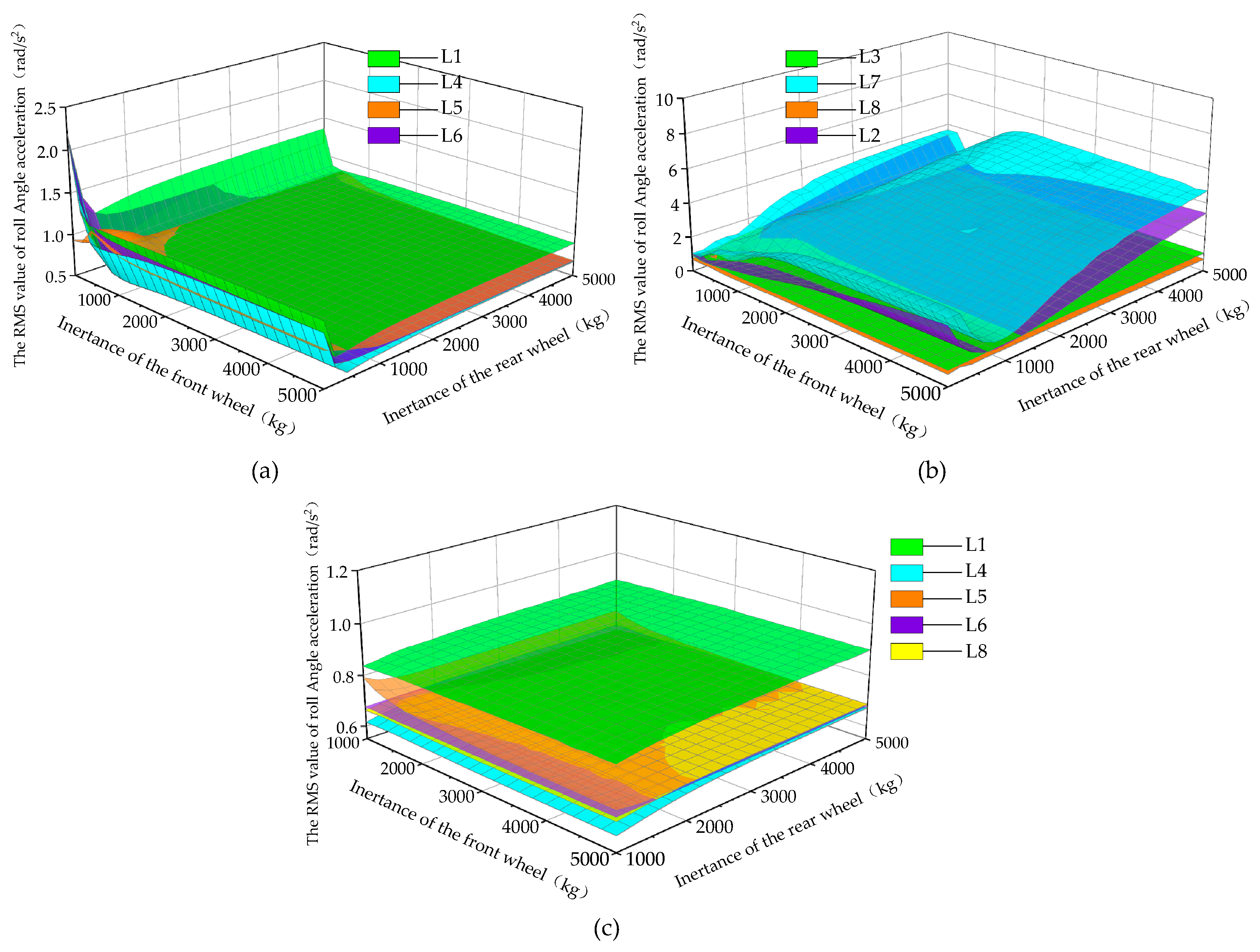
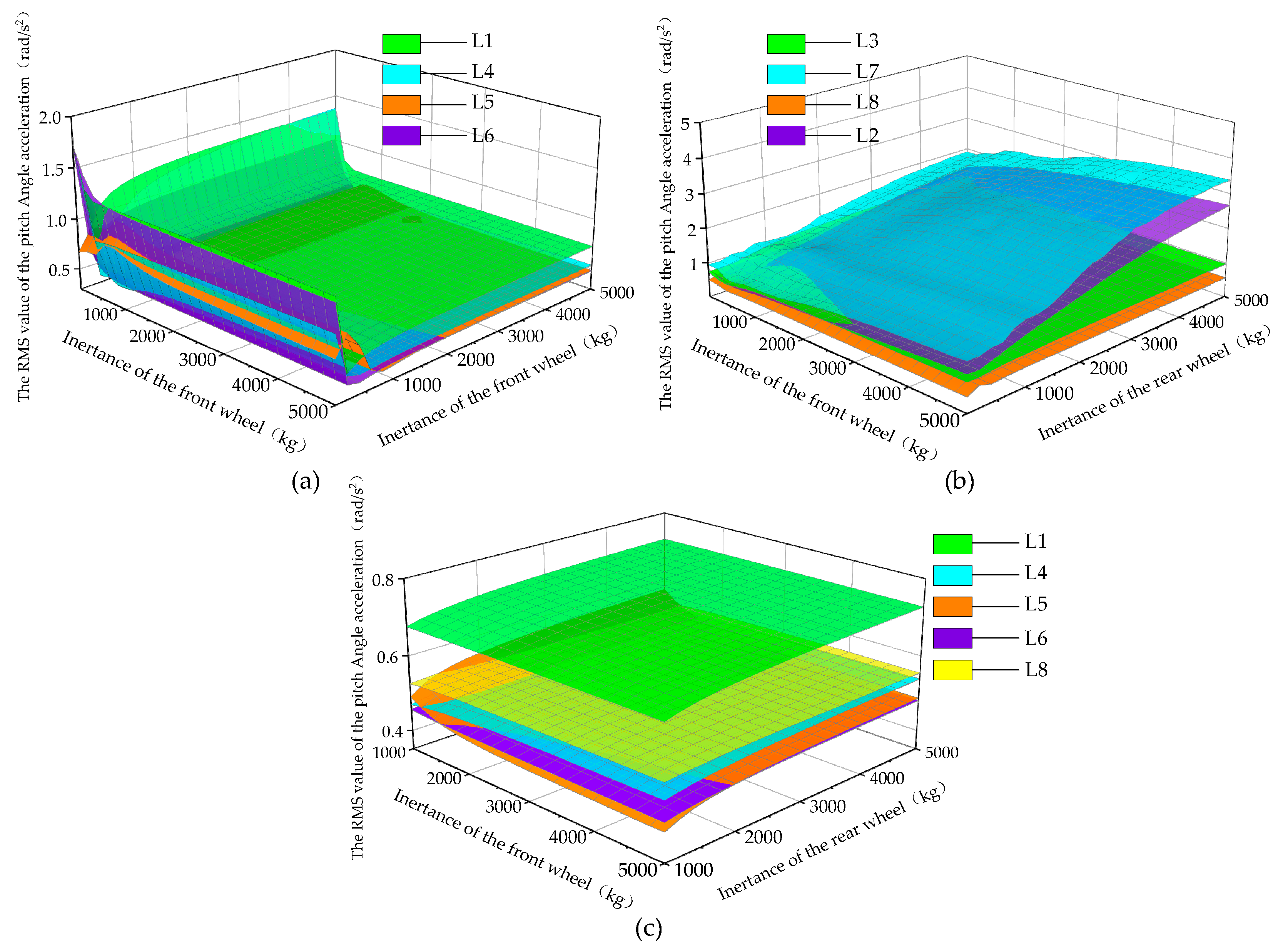
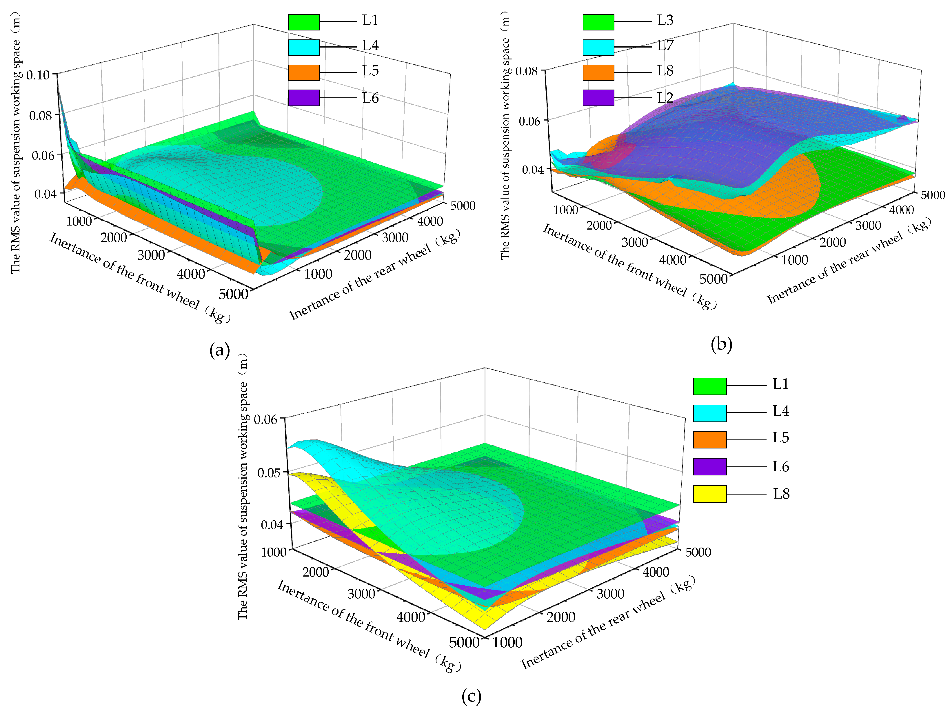
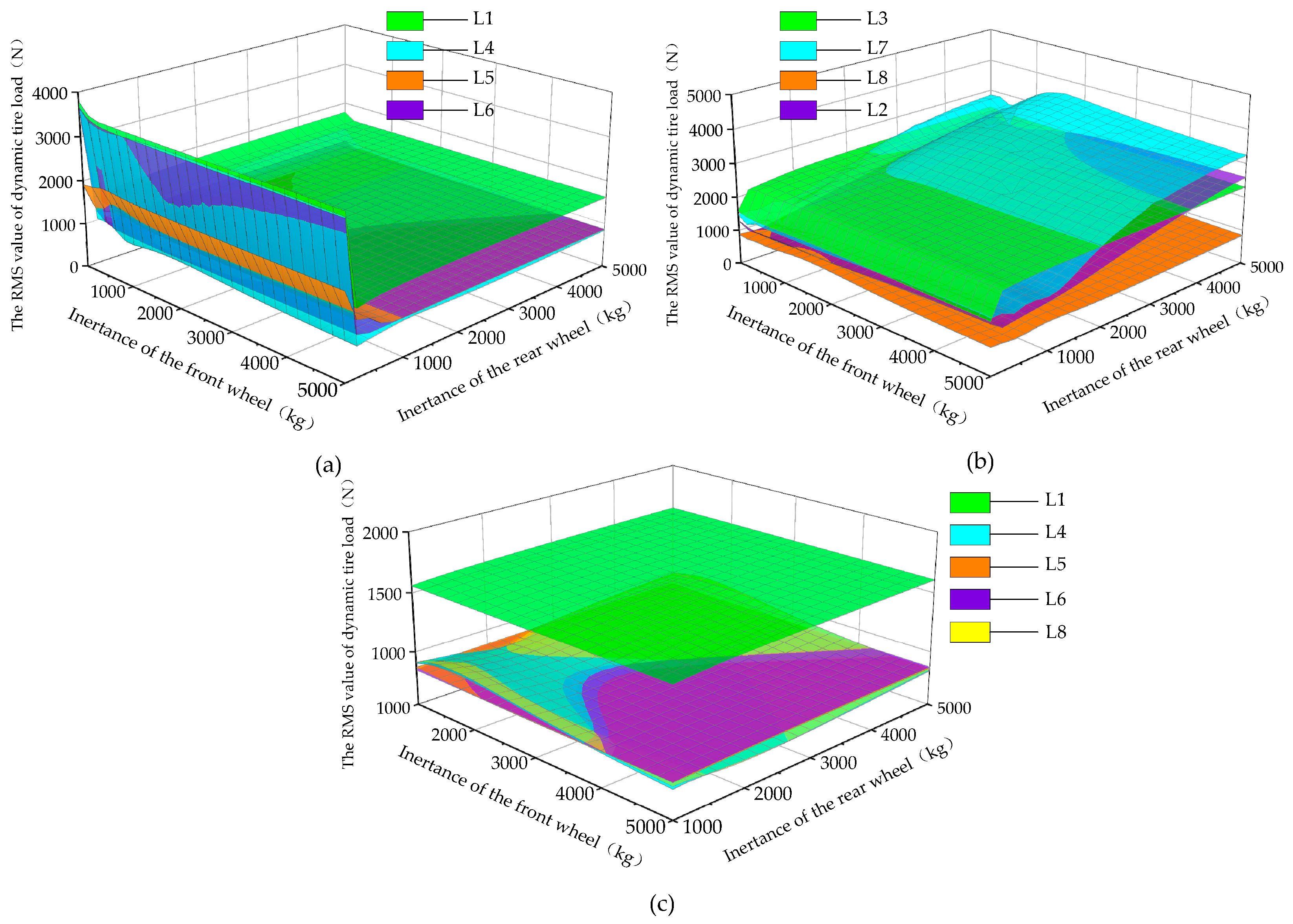
This paper aims to investigate the effects of ISD suspension topology on vertical, roll, and pitch dynamic responses under steering braking conditions. The inertial factor is considered to be the main factor affecting the anti-roll and anti-pitch stability of ISD suspension. By analyzing the linear increase in the inertance, the suitability of ISD suspension can be evaluated. Therefore, eight kinds of improved ISD suspension are studied, and the remaining parameters are kept unchanged. The simulation analysis was carried out only by gradually increasing the inertance (0~5000 kg) of the front and rear wheels linearly. The random input model is used as the road random excitation; the road grade is B, the initial speed is 20 m/s, the steering angle of the front wheel is 6° step input, and the clamp brake is braking under the maximum pipeline pressure. Figure 5, Figure 6, Figure 7, Figure 8 and Figure 9 show the simulation results; among them, (a) and (b) are the variation rules of the eight structural performance indicators, and (c) is the local amplification of the variation rules of the performance indicators of the six results with relatively similar results at (1000~5000 kg).
According to the results, eight kinds of ISD suspension structures are divided into two groups. The results of L1, L4, L5, and L6 were relatively stable, while the results of L2, L3, L7, and L8 were relatively volatile.
As can be seen from Figure 5, Figure 6, Figure 7, Figure 8 and Figure 9, with the increase in inertance, the performance indexes of L4, L5, L6, and L8 structures in the range of 0–200 kg inertance of the front wheel significantly decline, and the overall vehicle performance tends to be stable. With the decrease in the RMS value of pitch angle and roll angle acceleration, it can be seen that the anti-pitch and anti-roll performance of vehicles can be improved with the increase in inertance. The vehicle acceleration, suspension working space, and dynamic tire load decrease significantly, which indicates that the ride comfort of L4, L5, L6, and L8 suspension structures is improved.
However, the performance indicators of L2 and L7 structures fluctuate overmuch, and there is no convergence trend. Among them, the pitch angle and roll angle acceleration are overlarge, which seriously affects the safety of the vehicle. The performance index of the L3 structure increases with the increase in inertance. Compared with the original “spring-damper” parallel structure, the performance index of the L3 structure deteriorates significantly, which limits the improvement in vehicle driving performance. The performance indexes of the L1 structure are higher than L4, L5, L6, and L8, and the dynamic tire load deteriorates seriously, and the road friendliness is poor, as shown in Figure 5c, Figure 6c, Figure 7c, Figure 8c and Figure 9c. Therefore, L1, L2, L3, and L7 are not selected as optimized structures.
Via comparative analysis, the variation law of vehicle dynamic performance response indexes of eight kinds of structures under steering braking conditions was obtained. L4, L5, L6, and L8 structures were selected as the next parameter optimization objects to study ISD suspension structures with better performance.

5. Optimization of Vehicle ISD Suspension Parameters Based on NSGA-II

Based on the NSGA algorithm, the NSGA-II algorithm [27] adopts a fast, non-dominated sorting method and elite genetic strategy to speed up the running speed of the program and uses the crowding degree method to realize the sorting of individuals in the region and find the optimal result to ensure that the optimal individual has a greater probability of being retained. Among them, the algorithm parameters selected in this paper are as follows: the initial population number is set to 200, the evolutionary maximum algebra is set to 100, the optimal coefficient is set to 0.3, and the stopping algebra is set to 200. The algorithm flow chart is shown in Figure 10.

5.1. Optimal Target Selection

The vertical, anti-pitch, and anti-roll stability are mainly considered in the above steering braking conditions. For the evaluation of vertical stability, the RMS value of body acceleration is selected as the optimization objective. For the evaluation of anti-pitch stability, the RMS value of pitch angle acceleration is selected as the optimization objective. For the evaluation of anti-roll stability, the RMS value of roll angle acceleration is selected as the optimization objective. In the optimization process, in order to reflect the effect of the inerter, keep the stiffness of the supporting spring unchanged, and other parameters to be optimized are X = [ k f , k r , c f , c r , b f , b r ] .
The objective function under steering braking condition J 1 , J 2 , and J 3 are obtained as follows:
min J 1 = B A ( X ) min J 2 = R A ( X ) min J 3 = P A ( X )
where J 1 , J 2 , and J 3 represent the objective functions of vertical stability, anti-pitch stability, and anti-roll stability, respectively; B A ( X ) , P A ( X ) , and R A ( X ) , respectively, represent the RMS values of body, pitch angle, and roll angle acceleration of the ISD suspension to be optimized.

5.2. Constraint Selection

First of all, the performance indexes for evaluating vertical, anti-pitch, and anti-roll stability should not be worse than those of passive suspension. Then, in the design of suspension parameters, considering that the working distance between the wheel and the body should be limited to a certain range and better grip should be ensured when the wheel is in contact with the road, the ISD suspension working space and dynamic tire load are designed to be smaller than those of passive suspension. Therefore, the optimization conditions are as follows:
s t B A ( X ) < B A p a s s R A ( X ) < R A p a s s P A ( X ) < P A p a s s D T L ( X ) D T L p a s s S W S ( X ) S W S p s s s U B < X < L B
In the above formula, D T L ( X ) represents the RMS value of the dynamic tire load of the left front wheel suspension; S W S ( X ) represents the RMS value of the suspension working space of the left front wheel; D T L p a s s represents the RMS value of the dynamic tire load of the left front wheel passive suspension; S W S p a s s represents the RMS value of suspension working space of the left front wheel passive suspension; U B represents the lower limit of the optimization target parameter, the values for [0, 0, 0, 0, 0, 0]; and L B represents the upper limit of the optimization target parameter, the values for [30,000, 30,000, 5000, 5000, 5000, 5000]. The performance indexes of passive suspension are shown in Table 2.

5.3. NSGA-Ⅱ Algorithm Steps

The fast, non-dominated sorting of the NSGA-Ⅱ algorithm is to sort the individuals in the population according to the Pareto level. The individuals with Pareto level 1 are not dominated by other individuals, which is called a non-dominated solution. In the first round of non-dominated sorting, the number of individuals n i dominated by each individual i and the set S I dominated by each individual i are recorded via traversal. At this point, the n i = 0 individual is recorded in the non-dominated set of level 1. Since the n i and the S I of each individual need to be traversed, the time complexity of a single target is O(N2), so the time complexity of M targets is O(MN2). In the second round of sorting, an individual i is removed from the non-dominated solution set of the previous round, and then an individual j is removed from S I . At this time, n i 1 is added to the non-dominated solution set of the next round. If n i = 0, this individual j is added to the non-dominated solution set. Therefore, the total time complexity of non-dominated sorting is O(MN2) = O(MN2) + O(N2).
Then, the crowding degree is calculated to establish the poset. The crowding degree is obtained by the sum of the subgoal differences of the individuals before and after the individuals. The crowding degree of the individual i in M subgoals is
P [ i ] d i s t a n c e = Σ k = 1 M ( P [ i + 1 ] f k P [ i 1 ] f k )
where P [ i ] f k is the value of the individual i subtarget f k .
Then, via the elite strategy, excellent individuals are retained, and their individual sets are put into the newly generated parent sets according to the Pareto level from small to large. When the Pareto level is k, and the individual sets with level k are put into the parent sets, the total number of parent sets is less than the total number of individuals. Then, the individual sets with level k + 1 are put into the parent sets. If the total number of parent sets is greater than the total number of individuals, then the crowding degree of all individuals with grade k + 1 should be calculated, the crowding degree is sorted from small to large, and a poset is established. The individuals in the partially ordered set are added to the parent set successively until the total number of individuals is equal, all individuals after the partially ordered set are eliminated, and all individuals whose Pareto level is greater than k + 2 are eliminated.

5.4. Optimization Result

After optimization by the NSGA-Ⅱ algorithm, the component parameters of four kinds of ISD suspension structures are obtained. The results of parameter optimization are shown in Table 3.

6. Simulation Analysis

In this section, the performance of four selected ISD suspensions is compared with that of passive suspension. In order to evaluate the integrated performance of inerter to improve vehicle ride comfort, anti-roll, and anti-pitch, the step steering braking and fishhook steering braking conditions were selected for simulation. The numerical simulation analysis was carried out in the Matlab environment, the sampling interval was set to 0.001 s, and the white noise with zero mean and 20 dB power was selected for the pavement input.

6.1. Load Transfer Rate

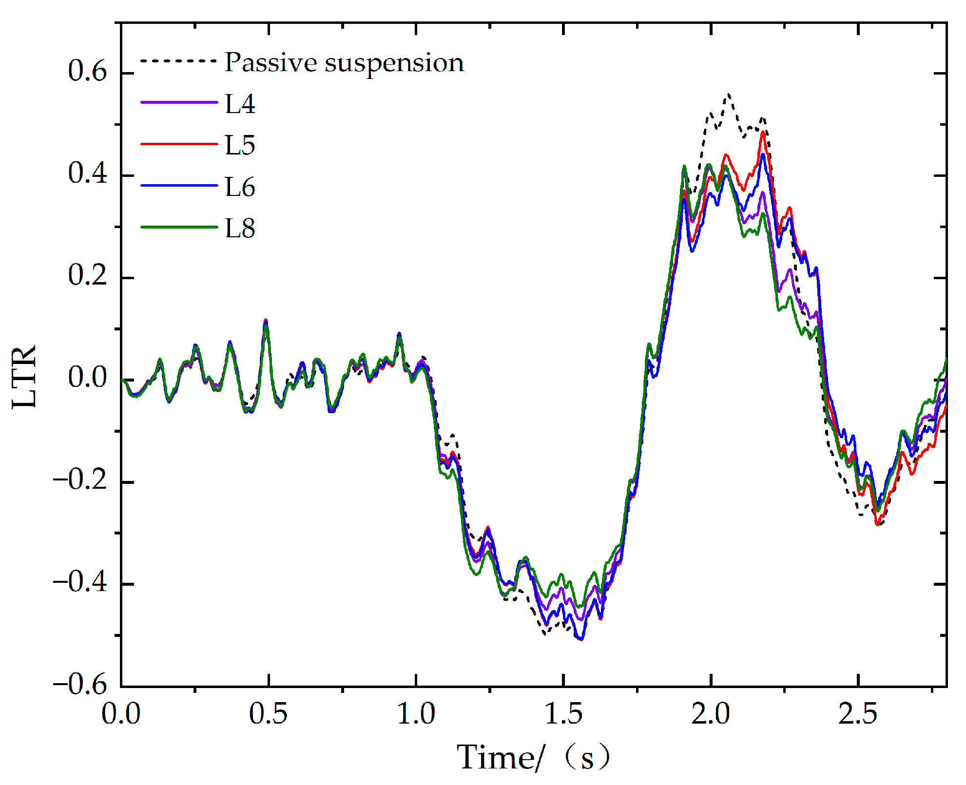
In addition to the roll angle acceleration to evaluate vehicle roll stability, this paper also uses lateral load transfer rate (LTR) to judge vehicle rollover risk [12], whose expression is
L T R = F z f r + F z r r F z f l F z r l F z f r + F z r r + F z f l + F z r l
When L T R = 1 , the vertical load on the left or right wheel is 0; this means that the vehicle is about to roll over. The vehicle roll risk can be judged by the value of L T R .

6.2. Step Steering Braking

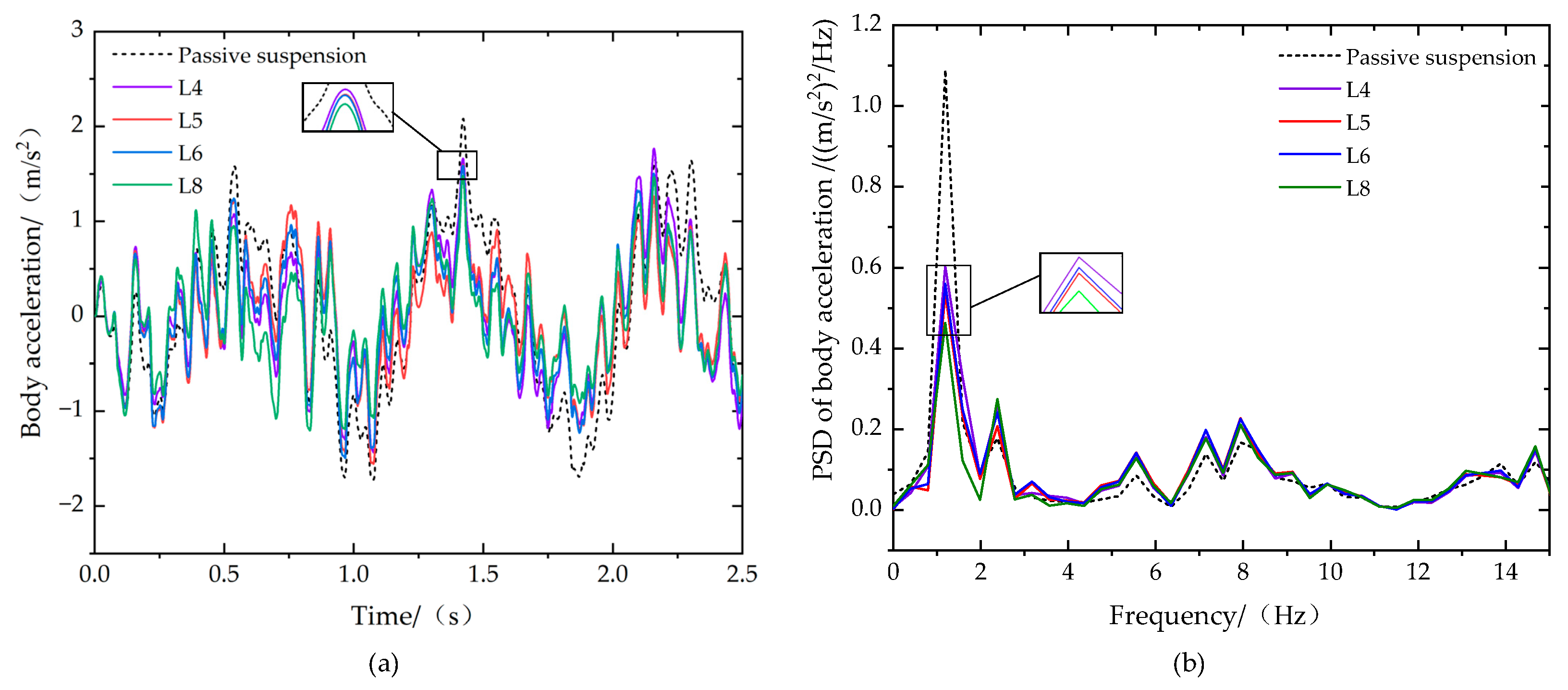
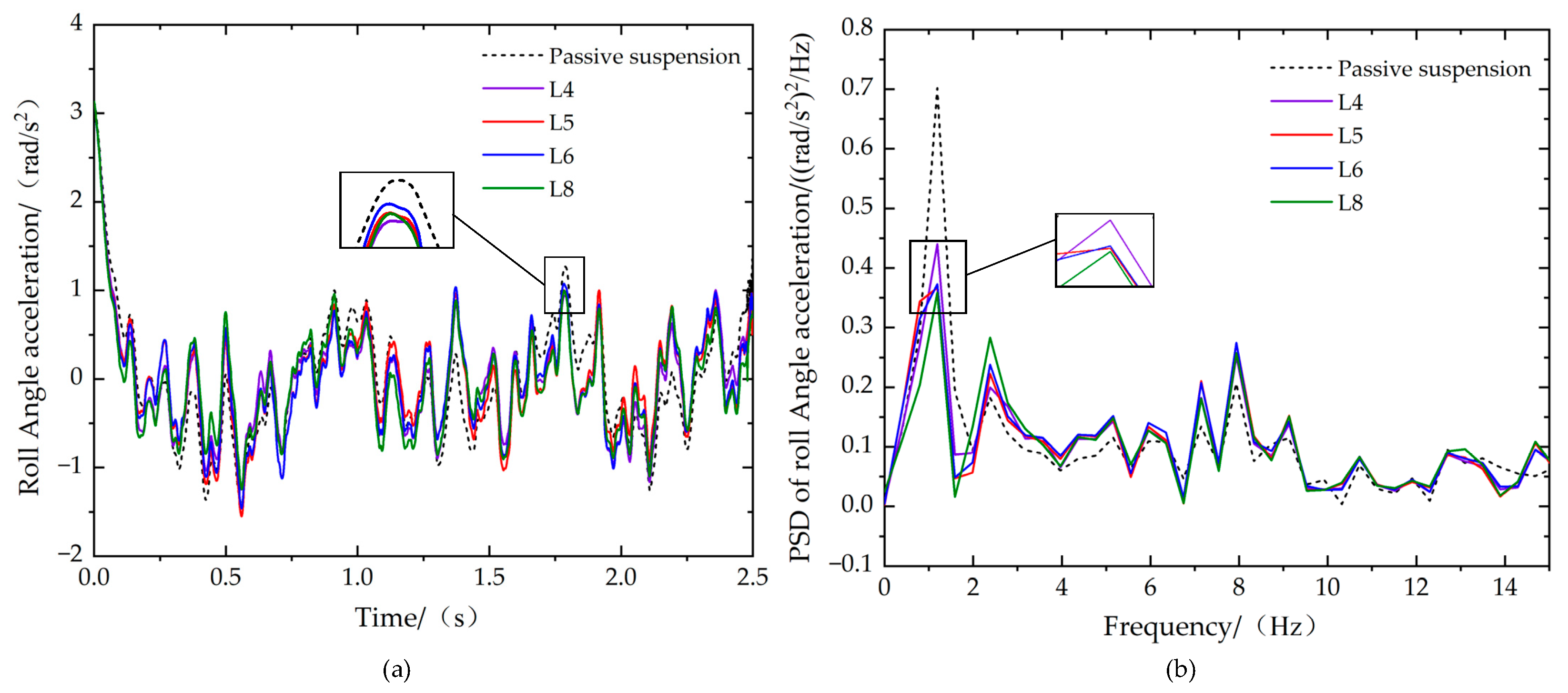
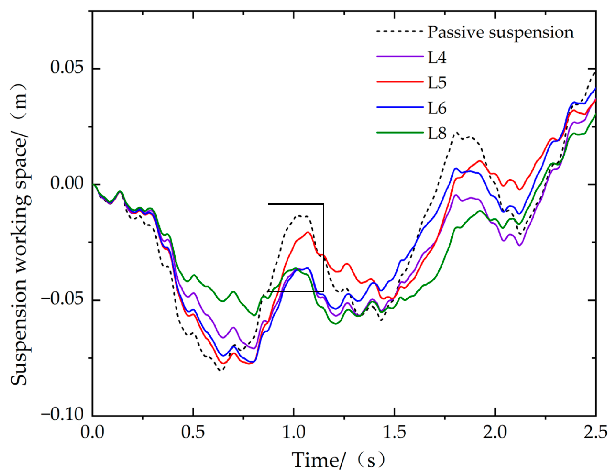
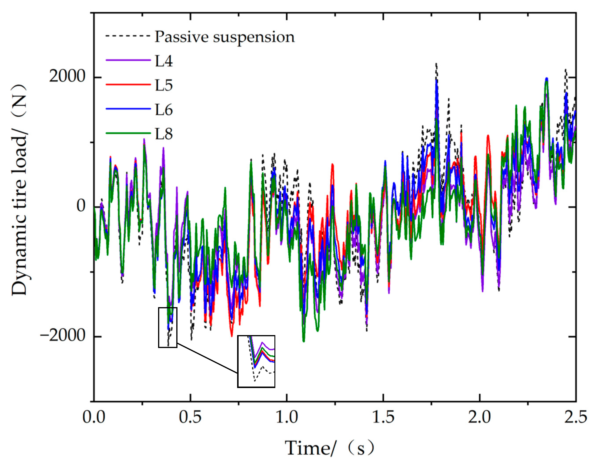
Table 4 is obtained by using the optimized parameter results in Table 3. The random input model is used as the road random excitation, the road grade is B, the initial speed is 20 m/s, the steering angle of the front wheel is 6° step input, and the clamp brake is braking under the maximum pipeline pressure. Figure 11, Figure 12 and Figure 13 show the comparison of body, roll angle, and pitch angle acceleration under 20 m/s step steering braking, respectively. On the basis of the time domain graph, the power spectral density (PSD) graph is obtained by Fourier series.
As shown in the time domain diagram in Figure 11a, Figure 12a and Figure 13a, compared with the passive suspension, the body, roll angle, and pitch angle acceleration are all improved to some extent. L8 has the most significant improvement in ride performance and roll resistance, and the RMS values of body and roll angle acceleration are reduced by 35.47% and 14.26%, respectively. L4 has the highest pitch resistance improvement, and the RMS acceleration of pitch angle acceleration decreases by 19.12%. Although there is a certain gap between L5 and L6 and the optimal value, compared with the passive suspension, the performance is significantly improved, and the RMS value of each acceleration is reduced by at least 10.35%. The small panel of the time domain diagram in Figure 11, Figure 12 and Figure 13 details the differences in body, roll, and pitch acceleration under step steering braking.
In the late braking period of the vehicle, due to the role of a larger braking force, the frequency of the vehicle will be reduced to a lower level (usually below 4 Hz), which is just in line with the sensitive area of the human body (0.4~4 Hz). In order to evaluate the vibration suppression ability of suspension in the sensitive frequency of the human body, the PSD of the body, roll angle, and pitch angle acceleration in the range of 0–15 Hz were selected. It can be seen from the frequency domain diagram in Figure 11b, Figure 12b and Figure 13b that the body, pitch angle, and roll angle acceleration PSD of the four structures are all reduced to a certain extent within the sensitive frequency of the human body, which proves that they can effectively improve the ride comfort, anti-roll, and anti-pitch ability of the vehicle under steering braking conditions. In the enhanced panel of the frequency domain diagram shown in Figure 11b, Figure 12b and Figure 13b, compared with the passive suspension, the body, roll angle, and pitch angle acceleration PSD of the four structures near 1 Hz (extreme value) are significantly reduced, and the low-frequency vibration isolation performance is significantly improved. Figure 14 and Figure 15 show the comparison of suspension working space and dynamic tire load under 20 m/s step steering braking.
As can be seen from Figure 14, the suspension working space of L8 has been significantly improved, and its RMS value has decreased by 6.92%. The suspension working space of L4, L5, and L6 structures has little change, but all was improved to some extent. As can be seen from the enhancement panel in Figure 15, the dynamic tire load of L4, L5, L6, and L8 is less than that of the passive suspension, of which L4 has improved by 18.05%.

6.3. Fishhook Steering Braking

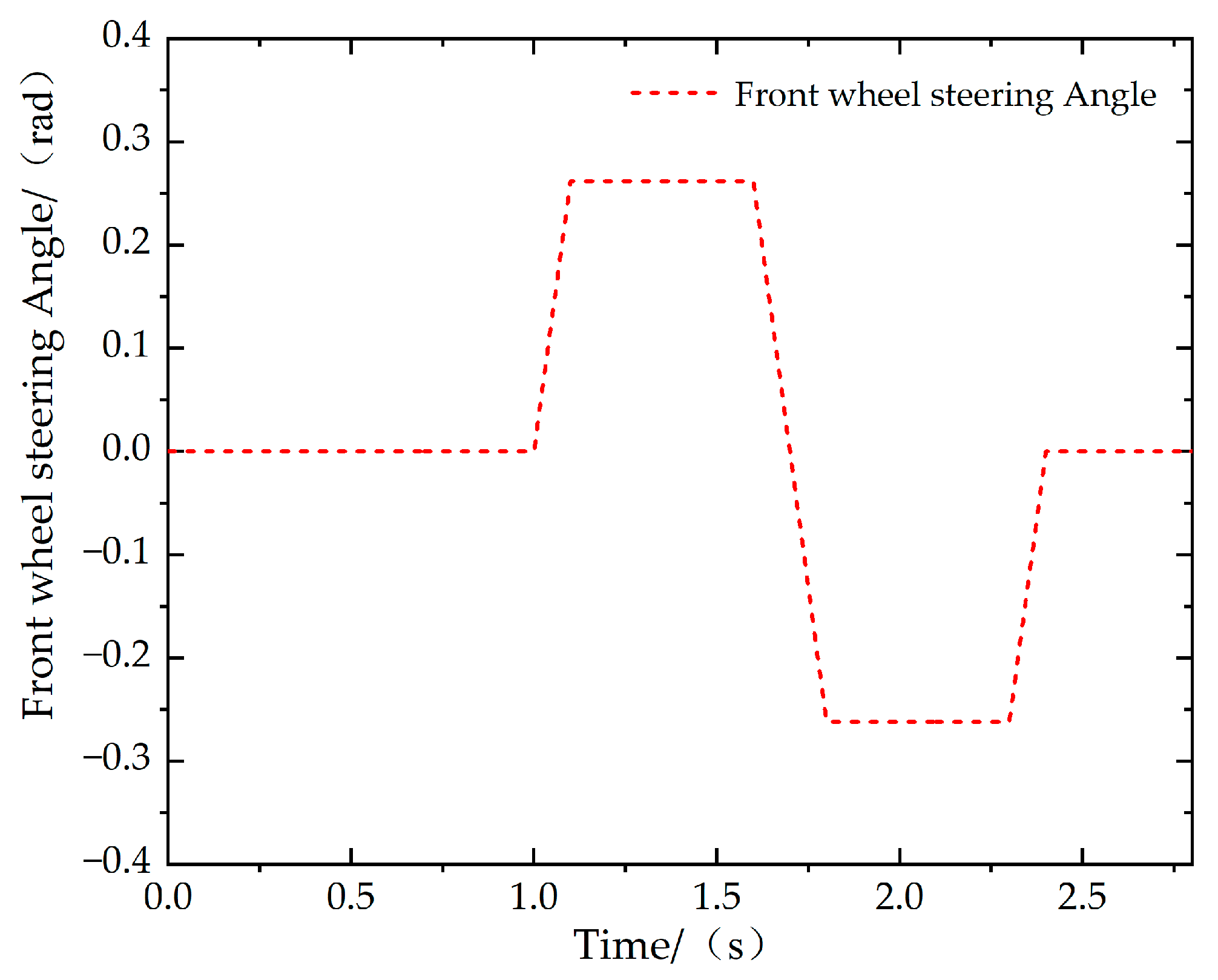
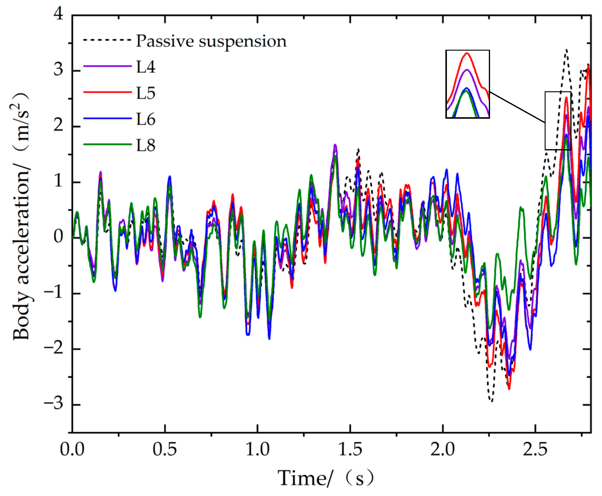
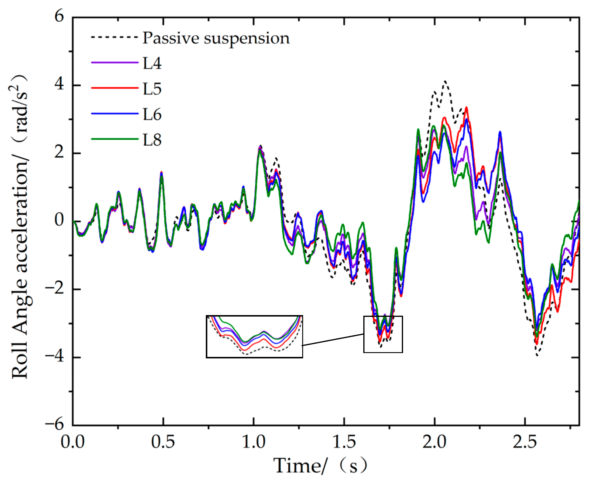
In order to evaluate the anti-rollover ability of the vehicle under extreme steering conditions, the fishhook steering of the front wheels, as shown in Figure 16, was selected. Figure 17, Figure 18 and Figure 19 shows the comparison of body, roll angle, and pitch angle acceleration under the steering braking of a 20 m/s fishhook.
As shown in Figure 17 and Figure 18, about 2 s after the second turn, body, and roll angle acceleration reach the maximum value, and the peak values of body and roll angle acceleration of L4, L5, L6, and L8 structures decrease significantly. From the aspect of peak time, the roll angle acceleration of L4, L5, L6, and L8 structures decreased by 32.49%, 18.47%, 26.83%, and 31.47%, respectively, compared with the passive suspension. Among them, the optimal structure in the literature [21] is the same as the L4 structure in this paper, but since the literature [21] only considers the vehicle roll stability performance under the steering of the fish hook, it can be concluded that the maximum of the vehicle roll angle of the optimal structure in the literature [21] at the speed of 80 Km/h is reduced by 39.84%, compared with the passive suspension, which corresponds to the results in this paper. It is proved that the ISD suspension structure can improve the roll stability performance of the vehicle. The enhancement panel shown in Figure 19 shows little change in pitch angle acceleration compared to the passive suspension. From the RMS value, only the L6 structure’s RMS value of pitch angle acceleration is less than that of the passive suspension, while the L4, L5, and L8 structures’ RMS value of pitch angle acceleration is also within the design’s acceptable range, controlled within 13%.
Figure 20 shows the change in LTR value during the steering braking of 20 m/s fishhook. As can be seen from the figure, the peak value of the lateral load transfer rate of ISD suspension at dangerous moments decreased significantly. Compared with passive suspension, L4, L5, L6, and L8 decreased by 25.74%, 13.17%, 20.94%, and 24.60%, respectively, indicating that the anti-roll performance of the vehicle was improved. The trend is consistent with the angular acceleration response of the roll angle acceleration.

7. Conclusions

In order to study the vertical, roll, and pitch stability of the vehicle, this paper builds the vehicle dynamic model and eight ISD suspension structures considering the steering braking of the vehicle.
The variation law of ISD suspension performance indexes in roll, vertical, and pitch motion was analyzed by using linear increasing inertance. The simulation results showed that the performance indexes of the four kinds of suspension tended to be stable, and their structures are, respectively, excluding the supporting spring in parallel, (1) an inerter in series with a spring and a damper in parallel, (2) a damper in series with a spring and an inerter in parallel, (3) an inerter and a damper in series, and (4) the damper in parallel with a spring and an inerter in series. And the effectiveness of increasing inertance in improving vehicle ride comfort, anti-roll, and anti-pitch performance was verified.
Using the simulation of step steering braking and fishhook steering braking on random road surfaces, compared with passive suspension, the four kinds of suspension can improve vehicle ride comfort, anti-roll, and anti-pitch ability under step steering braking conditions, especially in the 0–4 Hz frequency range, the vibration suppression effect is obvious. It shows that the ISD suspension structure can effectively improve the ride comfort and anti-roll and anti-pitch performance of the vehicle. Under fishhook steering braking conditions, lateral load transfer was considered as an index to evaluate vehicle rollover risk. The ride comfort and roll resistance of the four kinds of suspension were significantly improved, and only the suspension consists of a supporting spring in parallel with an inerter, and a damper in series took pitch stability into account.

Author Contributions

Formal analysis, K.Z.; Methodology, Y.L.; Supervision, F.D. and X.Y.; Writing—original draft, D.S. All authors have read and agreed to the published version of the manuscript.

Funding

The work was supported by the National Natural Science Foundation of China (Grant number: 52072157) and the Postdoctoral Science Foundation of China (Grant number: 2022M721385).

Data Availability Statement

The data will be made available upon request by the corresponding author.

Conflicts of Interest

The authors declare no conflict of interest.

References

  1. Qin, Y.; Zhao, Z.; Wang, Z.; Li, G. Study of Longitudinal—Vertical Dynamics for In-Wheel Motor-Driven Electric Vehicles. Automot. Innov. 2021, 4, 227–237. [Google Scholar] [CrossRef]
  2. Zhao, D.; Yin, Y.; Ni, T.; Zhang, W. Research review on Chassis Integrated Control of Heavy Truck. J. Yanshan Univ. 2020, 44, 189–197. [Google Scholar]
  3. Pan, G.; Ding, C.; Wang, W.; Li, A. Application of extended zero moment point in vehicle pitch control evaluation and Active control. J. Jiangsu Univ. 2021, 42, 85–91. [Google Scholar]
  4. Jiang, Z.; Zheng, M.; Zhang, N. Research on Pitch dynamics of semi-active anti-pitch Hydraulic Interconnected Suspension. J. Vib. Shock. 2020, 39, 272–278. [Google Scholar]
  5. Wu, X.; Zhou, B.; Wen, G. Research on Anti-roll Control of Hydraulic Interconnected Suspension. China J. Highw. Transp. 2018, 31, 123–132. [Google Scholar]
  6. Zhang, L.; Meng, Q.; Chen, H.; Huang, Y.; Liu, Y.; Guo, K. Kalman Filter-Based Fusion Estimation Method of Steering Feedback Torque for Steer-by-Wire Systems. Automot. Innov. 2021, 4, 430–439. [Google Scholar] [CrossRef]
  7. Qin, Y.; Wang, Z.; Yuan, K.; Zhang, Y. Correction to: Comprehensive Analysis and Optimization of Dynamic Vibration-Absorbing Structures for Electric Vehicles Driven by In-Wheel Motors. Automot. Innov. 2020, 3, 192. [Google Scholar] [CrossRef]
  8. Wang, J.; Liu, Z.; Meng, L.; Fu, T.; Li, J.; Wang, Z. Design and Research of Electro-Hydraulic Suspension System with both Energy Feed and active anti-roll Function. J. Automot. Eng. 2023, 13, 396–407. [Google Scholar]
  9. Hou, X.; Zhang, J.; Liu, W.; Ji, Y. LuGre Mode-based Longitudinal Ride Comfort Control of Vehicle during the Post-braking Phase. In Proceedings of the 2020 Chinese Automation Congress (CAC), Shanghai, China, 6–8 November 2020; IEEE: Piscataway, NJ, USA, 2020. [Google Scholar]
  10. Xu, Z.; Liu, H.; Dang, W.; Hu, C.; Long, Y. Research Review of Automobile Brake Comfort Control. Sci. Technol. Eng. 2022, 22, 6790–6801. [Google Scholar]
  11. Bi, H.; Lu, F.; Duan, S.; Huang, M.; Zhu, J.; Liu, M. Two-level principal–agent model for schedule risk control of IT outsourcing project based on genetic algorithm. Eng. Appl. Artif. Intell. 2020, 91, 103584. [Google Scholar] [CrossRef]
  12. Wen, H.; Wang, S.; Lu, F.; Feng, M.; Wang, L.; Xiong, J.; Si, M. Colony search optimization algorithm using global optimization. J. Supercomput. 2022, 78, 6567–6611. [Google Scholar] [CrossRef]
  13. Li, S.; Du, P.; Feng, X. Integrated Control Strategy of anti-rollover Chassis for Minibus. J. Jiangsu Univ. 2022, 43, 131–138. [Google Scholar]
  14. Zhao, S.; Li, Y.; Yu, Q. Vehicle Stability Control Based on Coordinated Control of Multiple Sub-systems of Chassis. J. Traffic Transp. Eng. 2015, 15, 77–85. [Google Scholar]
  15. Chen, L.; Chen, M.; Sun, X.; Cai, Y.; Pak, K.W.; Wu, Z. Lateral Dynamics Modeling and Stability Analysis of Air Suspension Bus. Automot. Eng. 2022, 44, 1746–1754. [Google Scholar]
  16. Huang, K.; Zhao, P.; Chen, J. Research on Improving Performance of Hydraulic Interconnected Suspension with Inertial Vessel. Noise Vib. Control. 2022, 42, 17–22. [Google Scholar]
  17. Lu, S.; Li, Y.; Zheng, L. Research on Vehicle active Rollover Control based on Brake and Suspension System. Automot. Eng. 2011, 33, 669–675. [Google Scholar]
  18. Smith, M.C. Synthesis of Networks: The inerter. IEEE Trans. Autom. Control. 2002, 47, 1648–1662. [Google Scholar] [CrossRef]
  19. Chen, L.; Yang, X.; Wang, R.; Huang, C.; Shen, Y. Study on the Performance of Improved ISD Three-Component Passive Suspension. Automot. Eng. 2014, 36, 340–345. [Google Scholar]
  20. Ge, Z.; Wang, W.; Li, G.; Rao, D. Design, Parameter Optimisation, and Performance Analysis of Active Tuned Inerter Damper (TID) Suspension for Vehicle. J. Sound Vib. 2022, 525, 116750. [Google Scholar] [CrossRef]
  21. Shen, Y.; Chen, L.; Liu, Y.; Zhang, X.; Yang, X. Improvement of the lateral stability of vehicle suspension incorporating inerter. Sci. China 2018, 61, 1244–1252. [Google Scholar] [CrossRef]
  22. Shen, Y.; Hua, J.; Fan, W.; Liu, Y.; Yang, X.; Chen, L. Optimal design and dynamic performance analysis of a fractional-order electrical network-based vehicle mechatronic ISD suspension. Mech. Syst. Signal Process. 2023, 184, 109718. [Google Scholar] [CrossRef]
  23. Shen, Y.; Jia, M.; Yang, X.; Liu, Y.; Chen, L. Vibration suppression using a mechatronic PDD-ISD-combined vehicle suspension system. Int. J. Mech. Sci. 2023, 250, 108277. [Google Scholar] [CrossRef]
  24. Luo, J.; Li, P.; Li, P.; Cai, Q. Observer-based multi-objective integrated control for vehicle lateral stability and active suspension design. J. Sound Vib. 2021, 508, 116222. [Google Scholar] [CrossRef]
  25. Feng, S.; Zhao, Y.; Deng, H.; Wang, Q.; Chen, T. Parameter Identification of Magic Formula Tire Model Based on Fibonacci Tree Optimization Algorithm. J. Shanghai Jiao Tong Univ. 2021, 26, 647–657. [Google Scholar] [CrossRef]
  26. Meng, L. Research on Active Anti-Roll Control Performance of Automotive Electro-Hydraulic Suspension. Ph.D. Dissertation, Jilin University, Changchun, China, 2023. [Google Scholar]
  27. Qi, Q.; Wu, T. Multi-objective Production Intelligent Scheduling Based on Improved NSGA-II Algorithm. Comput. Technol. Dev. 2021, 31, 162–168. [Google Scholar]
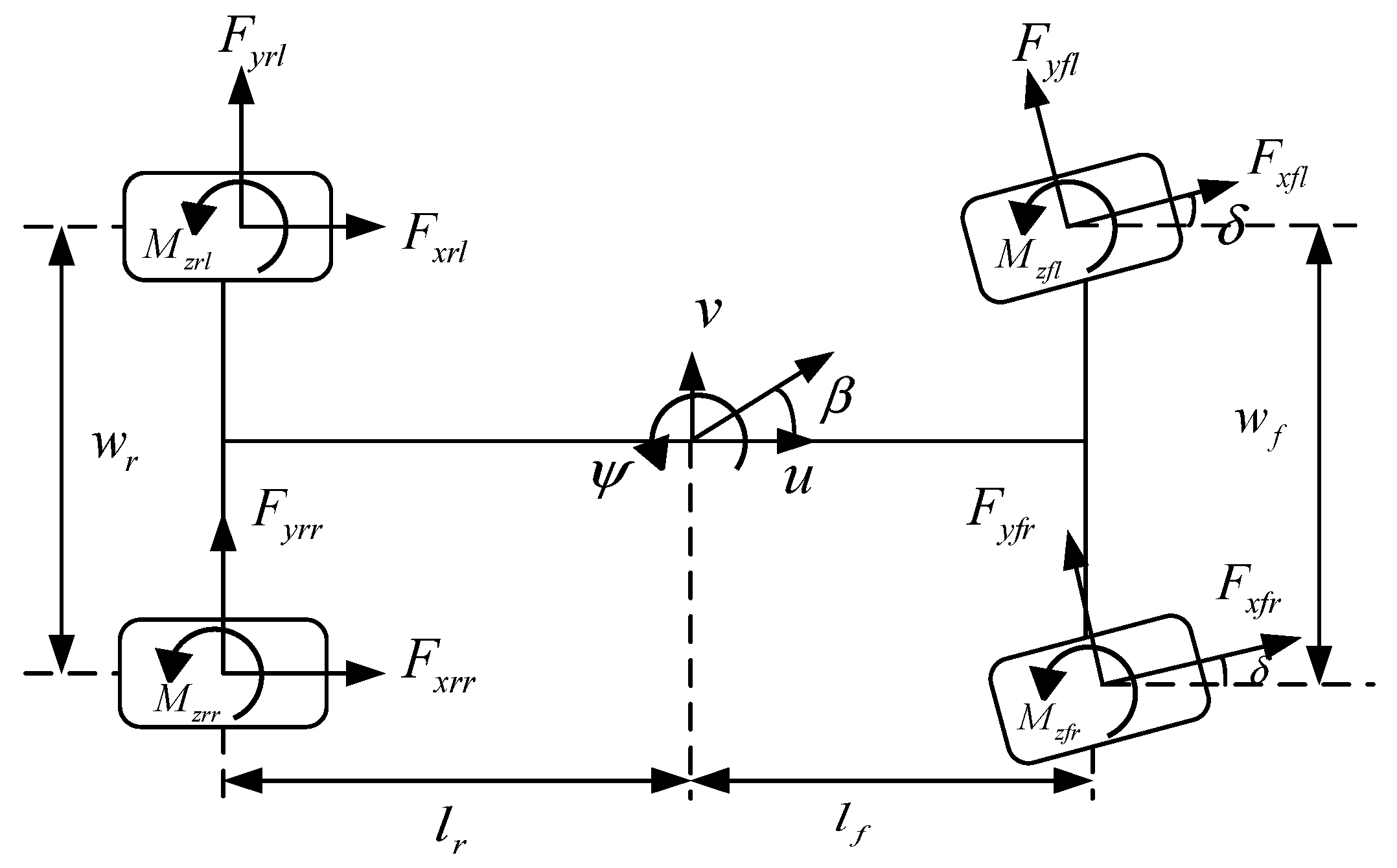
Figure 1. Steering motion model.
Wevj 14 00297 g001
Figure 2. Vehicle motion model.
Wevj 14 00297 g002
Figure 3. Eight improved ISD suspension topologies.
Wevj 14 00297 g003
Figure 4. Vertical input displacement of left and right wheel pavement.
Wevj 14 00297 g004
Figure 5. The variation rule of the RMS value of vehicle body acceleration. (a) The vehicle body acceleration law of L1, L4, L5, and L6; (b) the vehicle body acceleration law of L2, L3, L7, and L8; (c) local amplification of the vehicle body acceleration of L1, L4, L5, L6, and L8.
Wevj 14 00297 g005
Figure 6. The variation law of the RMS value of roll angle acceleration. (a) The roll angle acceleration law of L1, L4, L5, and L6; (b) the roll angle acceleration law of L2, L3, L7, and L8; (c) local amplification of the roll angle acceleration of L1, L4, L5, L6, and L8.
Wevj 14 00297 g006
Figure 7. The variation rule of the RMS value of the pitch angle acceleration. (a) The pitch angle acceleration law of L1, L4, L5, and L6; (b) the pitch angle acceleration law of L2, L3, L7, and L8; (c) local amplification of the pitch angle acceleration of L1, L4, L5, L6, and L8.
Wevj 14 00297 g007
Figure 8. The variation rule of RMS value of suspension working space. (a) The suspension working space law of L1, L4, L5, and L6; (b) the suspension working space law of L2, L3, L7, and L8; (c) local amplification of the suspension working space of L1, L4, L5, L6, and L8.
Wevj 14 00297 g008
Figure 9. The variation rule of RMS value of dynamic tire load. (a) The dynamic tire load law of L1, L4, L5, and L6; (b) the dynamic tire load law of L2, L3, L7, and L8; (c) local amplification of the dynamic tire load of L1, L4, L5, L6, and L8.
Wevj 14 00297 g009
Figure 10. Flowchart of NSGA-Ⅱ algorithm.
Wevj 14 00297 g010
Figure 11. Body acceleration under step steering braking. (a) Time domain diagram of body acceleration; (b) frequency domain diagram of body acceleration.
Wevj 14 00297 g011
Figure 12. Roll angle acceleration under step steering braking. (a) Time domain diagram of roll angle acceleration; (b) frequency domain diagram of roll angle acceleration.
Wevj 14 00297 g012
Figure 13. Pitch angle acceleration under step steering braking. (a) Time domain diagram of pitch angle acceleration; (b) frequency domain diagram of pitch angle acceleration.
Wevj 14 00297 g013
Figure 14. Suspension working space under step steering braking.
Wevj 14 00297 g014
Figure 15. Dynamic tire load under step steering braking.
Wevj 14 00297 g015
Figure 16. Front-wheel steering angle.
Wevj 14 00297 g016
Figure 17. Body acceleration under fishhook steering braking.
Wevj 14 00297 g017
Figure 18. Roll angle acceleration under fishhook steering braking.
Wevj 14 00297 g018
Figure 19. Pitch angle acceleration under fishhook steering braking.
Wevj 14 00297 g019
Figure 20. Lateral load transfer rate.
Wevj 14 00297 g020
Table 1. Vehicle parameters.
ParameterValue
Vehicle mass mt/kg1659
Sprung mass ms/kg1410
Front wheel unsprung mass mufl,mufr/kg26.5
Rear wheel unsprung mass murl,murr/kg24.4
Left wheel base wf/m1.574
Left and right wheel base wr/m1.593
Distance from front axle to center of mass lf/m1.278
Distance from rear axis to center of mass lr/m1.430
Height of center of mass h1/m0.50
Roll height h2/m0.40
Distance from center of roll to center of mass h3/m0.25
Body roll moment of inertia Ix/kg·m2925
Body pitch moment of inertia Iy/kg·m22577
Body yaw moment of inertia Iz/kg·m22603
Wheel inertia Iw/kg·m20.99
Wheel radius Rw/m0.345
Front suspension spring stiffness of the original model kf0/kN·m−125
Rear suspension spring stiffness of the original model kr0/kN·m−122
Front suspension damping coefficient of the original model cf0/N·s·m−11800
Rear suspension damping coefficient of the original model cr0/N·s·m−11500
Tire stiffness kt/kN·m−1192
Front suspension roll stiffness k1/N·m·rad−147,298
Rear suspension roll stiffness k2/N·m·rad−137,311
Table 2. Performance index of passive suspension.
Performance IndexRMS Value
Body acceleration/(m·s−2)0.8684
Roll angle acceleration/(rad·s−2)0.6338
Pitch angle acceleration/(rad·s−2)0.4885
Suspension working space/(m)0.0395
Dynamic tire load/(KN)0.8771
Table 3. Parameter optimization result.
Suspension Structure k f (N/m) k r (N/m) c f (N∙s/m) c r (N∙s/m) b f (kg) b r (kg)
L411,39517,269221328953764514
L528,70883102860340610233484
L6//2815342531683614
L8858316,313297124211022180
Table 4. Suspension performance index RMS value and improvement.
RMS ValueL4ImprovementL5ImprovementL6ImprovementL8Improvement
Body acceleration/(m·s−2)0.654224.67%0.608929.88%0.623027.51%0.560435.47%
Roll angle acceleration/(rad·s−2)0.597212.61%0.612610.35%0.610710.64%0.585914.26%
Pitch angle acceleration/(rad·s−2)0.395119.12%0.377610.35%0.407716.54%0.45676.52%
Suspension working space/(m)0.03891.44%0.03832.78%0.03940.20%0.03686.92%
Dynamic tire load/(kN)0.718818.05%0.80338.42%0.79059.88%0.746514.90%
Disclaimer/Publisher’s Note: The statements, opinions and data contained in all publications are solely those of the individual author(s) and contributor(s) and not of MDPI and/or the editor(s). MDPI and/or the editor(s) disclaim responsibility for any injury to people or property resulting from any ideas, methods, instructions or products referred to in the content.