Article

Research on Parameter Optimization Design Method for Dual-Motor Coupled Drive System

China North Vehicle Research Institute, Beijing 100072, China
*
Author to whom correspondence should be addressed.
World Electr. Veh. J. 2023, 14(10), 282; https://doi.org/10.3390/wevj14100282
Submission received: 5 August 2023 / Revised: 12 September 2023 / Accepted: 13 September 2023 / Published: 8 October 2023
(This article belongs to the Special Issue New Energy Special Vehicle, Tractor and Agricultural Machinery)

Abstract

:
To improve energy utilization efficiency and extend the driving range of electric vehicles, this paper proposes a Dual-Motor Coupled Drive System (DMCDS) with a simple structure and establishes a dynamic mathematical model to analyze power flow characteristics under different driving modes. Considering the interdependence between the optimization of component sizes and system control in multi-motor drive systems, a two-layer hybrid optimization method is proposed to determine the optimal component sizes, balancing vehicle performance with minimal system energy losses. To evaluate the effectiveness of the proposed optimization design method, extensive simulation analysis was carried out in MATLAB. The results demonstrate that the optimization of motor sizes and gear ratios can enhance the energy efficiency of the drive system. In comparison with prototype scheme before optimization, the high-efficiency region utilization of motors EM_R and EM_S increased by 45% and 48%, respectively. Compared with the prototype and single-motor drive system, the average drive efficiency after optimization increased by 2.5% and 4.2%, respectively, and the energy consumption per 100 km decreased by 3.6% and 6.8%, respectively. These results confirm the efficacy of the proposed optimization design method in achieving an energy-saving effect.

1. Introduction

As global petroleum resources continue to deplete rapidly and air quality worsens, electric vehicles have been experiencing rapid advancements [1]. Pure electric vehicles have diverse energy sources, such as wind, solar, and hydro power, providing advantages like simple structures and zero emissions in comparison to conventional vehicles [2]. However, the main challenge for electric vehicles remains their limited energy density, long charging times, and restricted driving range due to current battery technology [3]. To mitigate these challenges, besides technological breakthroughs in batteries, the widely embraced and most effective solution lies in reducing the energy losses in the drive system [4]. In pursuit of this objective, a plethora of methods have been proposed, primarily focusing on powertrain configurations, energy management strategies (EMSs), and component size optimization.
At present, the powertrains of EVs on the market are mostly driven by a single motor coupled to a single-speed transmission. The utilization of a single-speed transmission offers a cost-effective solution by effectively reducing the mass, volume, and cost [5,6,7]. However, the single-motor drive systems exhibit a lower efficiency at low torques and low speeds, leading to a higher probability of the motor operating within the low-efficiency region. Therefore, it is necessary to find other powertrain structures that can improve drive efficiency. Many studies have shown that dual-input coupling powertrain systems have been widely used in electric vehicles to reduce energy consumption and improve efficiency [8,9,10,11]. Utilizing two smaller motors instead of a single high-power source allows for a reduction in the torque capacity of each individual motor, thereby facilitating the development of high-speed motors and increasing the power density of the drive system. Moreover, the operating points of the two motors can be adjusted to optimize the efficiency of the drive system [12].
After determining the powertrain configuration, the subsequent task involves optimizing the component sizes and designing the EMS for the drive system [13]. Regarding EMS design, stochastic dynamic programming (SDP) [14], Pontryagin’s Maximum Principle (PMP) [15], and the dynamic programming (DP) algorithm [16] are widely employed optimization algorithms. The DP algorithm can provide a global optimal strategy when the entire driving cycle information is available. Nevertheless, its real-time online application is limited as it necessitates knowledge of future road grade and vehicle speed information [17].
Currently, some research progress has been made in the optimization of drive system parameters. References [18,19,20] utilized genetic algorithms and particle swarm optimization (PSO) algorithms to optimize the component parameters of hybrid drive systems, resulting in reduced energy consumption. However, these studies only performed static optimization of the objective function during parameter optimization, without considering the impact of component parameter variations on the high-efficiency region and the coordinated control of power sources. Focusing on a single aspect alone cannot achieve optimal system performance; instead, an integrated optimization of both component parameters and system control strategies is required.
In recent years, researchers around the world have made notable progress in cooperative optimization methods and double-layer control strategies [21,22,23,24,25]. Angelo et al. proposed a novel double-layer control architecture designed to drive the longitudinal motion of electric vehicles. The control architecture, by combining the two control strategies, can reduce the overall energy consumption of electric vehicles [26]. Fathy et al. demonstrated the significant influence of control strategy optimization on the effectiveness of parameter optimization, affirming the existence of coupling between parameter optimization and control strategy optimization [27]. Fang et al. identified Pareto optimal solutions using a comprehensive optimization approach to concurrently optimize powertrain components and control systems [28]. In the context of multi-mode hybrid electric vehicles, Zhuang integrated energy management control strategy optimization, topology configuration optimization, and component parameter matching, proposing both cage optimization and iterative optimization architectures. The results demonstrated that the iterative optimization architecture efficiently converged to the global optimal solution [29]. Nguyen et al. proposed a two-loop optimization algorithm, combined with the global search method and non-dominated sorting genetic algorithm-II to find optimal motor sizes and transmission ratios for the powertrain of electric vehicles equipped with two motors and multi-gear ratios. The simulation results showed that the optimization of both motor sizes and gear ratios considerably enhances the energy efficiency of the powertrain system [30].
The objective of this research is to develop a dual-motor coupled drive system for electric vehicles that enhances the vehicle’s energy efficiency while ensuring dynamic performance. To further improve the energy utilization efficiency of the DMCDS, a two-layer hybrid optimization method is proposed to synergistically optimize the system component sizes and control strategies. Through simulation experiments, the optimal control parameters are determined, and the most suitable parameter configuration for the driving cycle conditions is identified.
The rest of this paper is organized as follows: Section 2.1 introduces the overall configuration of the DMCDS. The modeling and driving modes of the DMCDS are displayed in Section 2.2. In Section 2.3, a two-layer hybrid optimization method is presented, which aims to determine the optimal parameters of the system components. The simulation results and discussion are given in Section 3, where two typical driving cycles are used to evaluate the effectiveness of the proposed method. Finally, the conclusions are presented in Section 4.

2. Materials and Methods

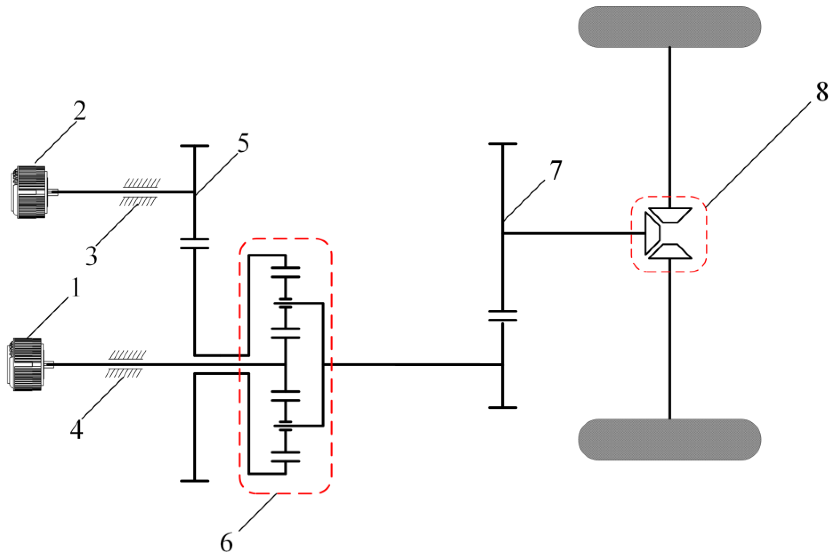
2.1. Configuration of DMCDS

As the central component of electric vehicles, the Dual-Motor Coupled Drive System exerts a direct impact on the dynamic performance of the vehicle. By conducting a comparative analysis of multiple configuration schemes, this study proposes a dual-motor coupled drive system configuration that incorporates a planetary gear mechanism as the power coupling device, as illustrated in Figure 1. It is mainly composed of two motors, EM_R and EM_S, two electromagnetic brakes, B1 and B2, and a power coupling gearbox. Notably, motors EM_S and EM_R are, respectively, linked to the sun gear and ring gear, while the carrier establishes a connection to the power output of the main reducer.

2.2. Modeling and Mode Analysis

2.2.1. Dynamics Modeling of DMCDS

The primary focus of this paper is to investigate a dual-motor coupled drive system, consisting of two motors, which achieve power coupling through the utilization of a planetary gear mechanism. In situations where the vehicle speed and required torque are known, the operational states of EM_S and EM_R are not uniquely determined for the DMCDS. By combining the static kinematic equations of the planetary gear mechanism with the dynamic model of the planetary gear set, we derive the dynamic model of the dual-motor coupled drive system as shown in the following equation.
{ ω ˙ m s = a ( T m s     T m r k   +   1 )     b ( T m s     T m r     2 T c k   +   1 ) a d     b c ω ˙ m r = c ( T m s     T m r k   +   1 )     d ( T m s     T m r     2 T c k   +   1 ) b c     a d ω ˙ c = ω ˙ m s   +   k ω ˙ m r 1   +   k = i m v ˙ a r w a = J r k   +   1 + 2 k J c ( k   +   1 ) 2 , b = ( J r k   +   1 + k J p ( k     1 ) 2 ) c = J s + 2 J c ( k   +   1 ) 2 , d = J s + 2 J p ( k     1 ) 2
where ωms, ωmr, and ωc are the output speeds of motors EM_S and EM_R, and the carrier, respectively; Tms, Tmr, and Tc are the output torque of motors EM_S and EM_R, and the planet carrier; Js, Jr, Jc, and Jp represent the equivalent moments of inertia of the sun gear, ring gear, carrier, and planetary gear, respectively; im, rw, and k denote the main reduction ratio, rolling radius of the wheels, and the planetary gear ratio, respectively; and va denotes the vehicle speed.

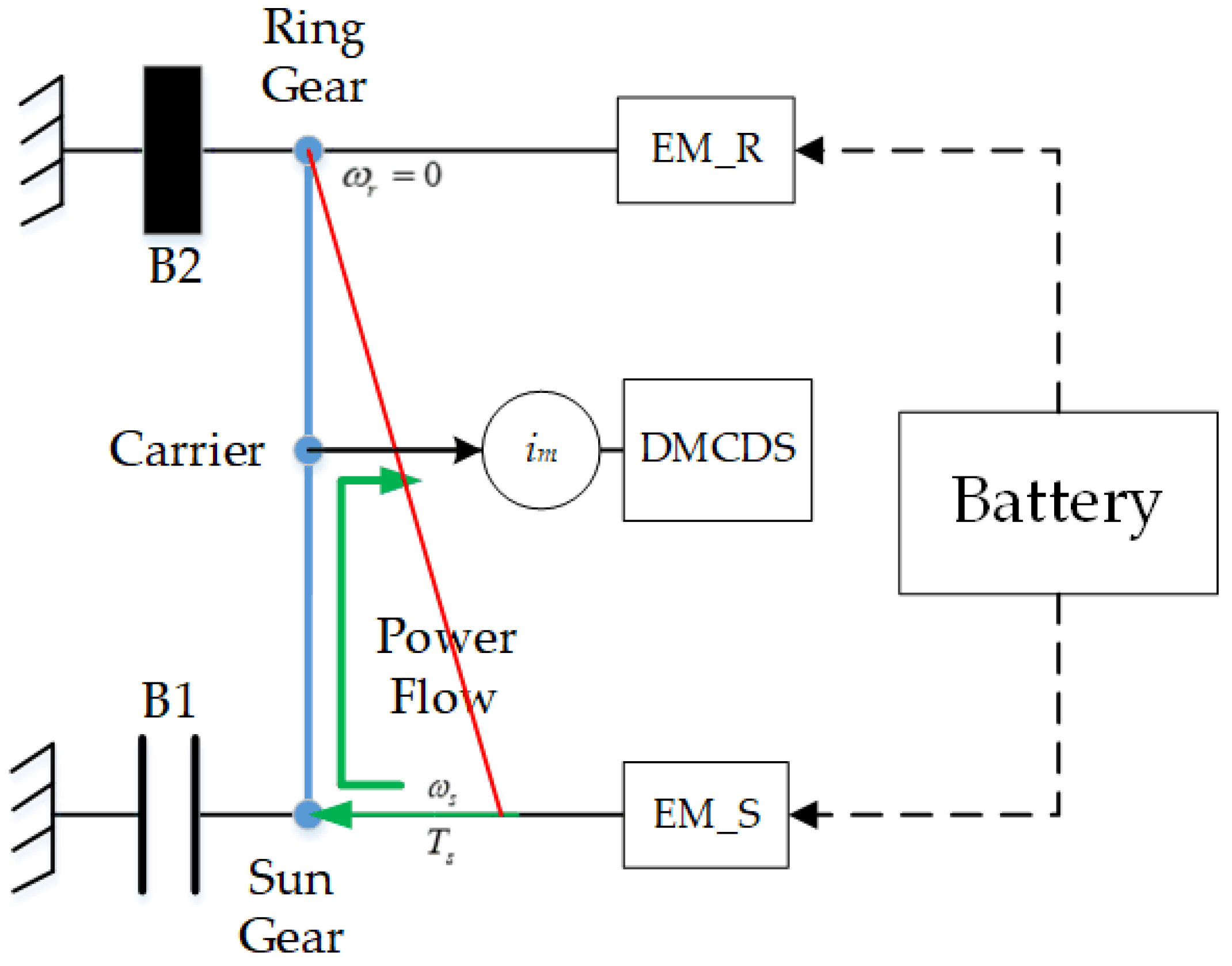
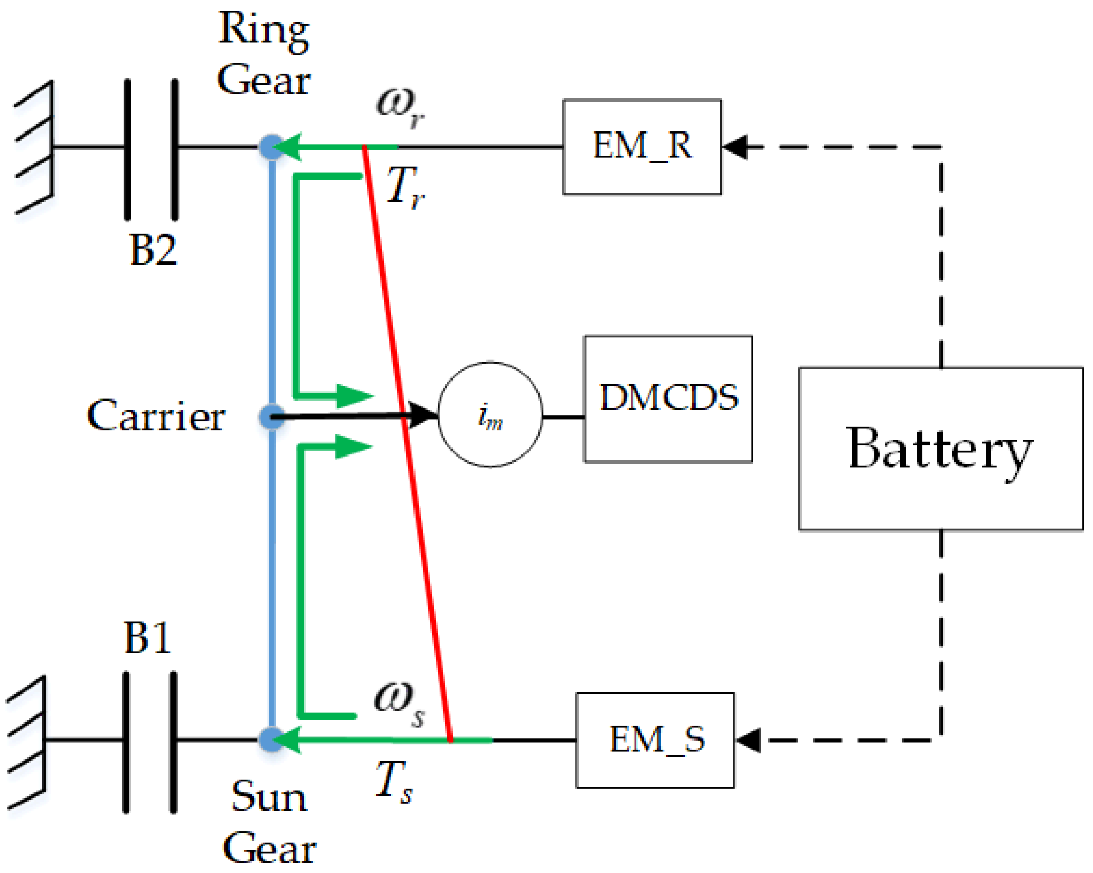
2.2.2. Driving Mode Analysis

The operational states of components in the DMCDS vary as it operates in different driving modes, leading to distinct dynamic mathematical models. Therefore, determining the operational states for different driving modes is crucial for the efficient functioning of the DMCDS. Through effective coordination of motor and brake controls, the DMCDS can seamlessly switch between three driving modes: Motor EM_S independent drive (M1S), Motor EM_R independent drive (M1R), and Dual-Motor Coupled Drive (DMC). Table 1 provides the working states of each component under different driving modes.
When operating in the M1S mode, the DMCDS disengages brake B1, engages brake B2, and deactivates motor EM_R. The power from motor EM_S is transmitted through the sun gear and output by the planet carrier, resulting in a higher transmission ratio for the system. This mode exhibits its advantage in situations where the vehicle requires significant torque at low speeds, allowing EM_S to operate efficiently in its high-efficiency region. It proves particularly effective for low-speed, high-torque scenarios, such as rapid acceleration and uphill driving. Figure 2 illustrates the equivalent lever model of the DMCDS.
Utilizing the equivalent lever model in conjunction with the dynamic model described by Equation (1), the dynamic mathematical model for the M1S mode can be deduced.
{ ( T m s J m s ω ˙ m s ) · ( 1   +   k ) T w i m = J c ω ˙ c J c ω ˙ c = m s r w 2 i m 2 · v ˙ a i m r w = m s r w v ˙ a i m ω m s = v a i m r w ( 1   +   k )
where Jms denotes the equivalent moment of inertia of motor EM_S, Tw denotes the load torque on the driving wheel, and ms denotes the vehicle weight.
When operating in the M1R mode, the DMCDS deactivates motor EM_S and engages brake B1 to apply a braking force on the sun gear, effectively transforming the DMCDS into a single-degree-of-freedom system. The output torque of EM_R is transmitted through the ring gear and planet carrier, delivering power to the wheels via the main reducer. Therefore, selecting the M1R mode when the vehicle demands higher power allows the system to leverage its advantages, with motor EM_R operating more efficiently within its high-efficiency range. Figure 3 illustrates the equivalent lever model of the DMCDS.
Utilizing the equivalent lever model in conjunction with the dynamic model described by Equation (1), the dynamic mathematical model for the M1S mode can be deduced.
{ ( T m r J m r ω ˙ m r ) 1 + k k T w i m = m s r w v ˙ a i m ω m r = v a i m r w · 1 + k k
where Jmr denotes the equivalent moment of inertia of motor EM_R.
When operating in the Dual-Motor Coupled Drive mode, the DMCDS disengages both brakes B1 and B2. Motors EM_S and EM_R operate simultaneously, with both motors providing power to the planetary gear mechanism. The equivalent lever model of the DMCDS in this mode is illustrated in Figure 4.
When the single-motor drive mode falls short of satisfying the high-power requirements or when the motor cannot operate within the high-efficiency range, the Dual-Motor Coupled Drive mode can be utilized. By adjusting the output speeds of both motors, continuous speed regulation is achieved, contributing to the improved operational efficiency of both motors. This mode proves advantageous for driving scenarios with substantial power demands or higher vehicle speeds. The dynamic model under the DMC drive mode can be represented as follows:
{ ( min ( T m s , T m r / k ) J m s ω ˙ m s J m r ω ˙ m r / k ) ( 1 + k ) = m s r w v ˙ a   +   T w i m ω m s + k ω m r = ( 1 + k ) v a i m r w

2.3. Parameter Optimization of DMCDS

2.3.1. Mathematical Models

(1)
Vehicle model
To examine the relationship between variations in vehicle speed and the output characteristics of the Dual-Motor Coupled Drive System, it is essential to establish a longitudinal vehicle dynamics model that accounts for slip ratio. Leveraging the system configuration and vehicle dynamics, the longitudinal dynamic model of the vehicle can be expressed as follows:
{ T c i m η t T w = J w ω ˙ w T w = ( m s g f r + C D A f v a 2 / 21.15 ) r w v a = ω w r w 1   +   λ ω w i m ( k + 1 ) = ω m s + k ω m r
where ωw, Tw, and Jw are the speed, torque, and moment of inertia of the wheel, respectively; fr is the tire rolling resistance coefficient; CD is the aerodynamic drag coefficient; Af is the vehicular frontal area; and λ is the slip ratio of the driving wheel. The values of the vehicle parameters are displayed in Table 2.
(2)
Motor model
In the domain of electric vehicles, the peak power of the motor is commonly determined by the acceleration demands. Consequently, if the acceleration time is pre-established, the total peak power of the two motors remains constant and can be expressed as
P max s + P max r = 2 P max b
where Pmaxs and Pmaxr are the peak power of motors EM_S and EM_R, respectively; and Pmaxb denotes the peak power of the baseline motor EMB, which equals half of the maximum vehicle power.
To maximize the average efficiency of the DMCDS under various driving cycles, selection of the power levels for the motors is essential. To streamline the model, the efficiency map of both motors has the same shape as motor EMB. As a result, EM_S and EM_R share the same speed range as EMB, while the torque range is proportional to their respective power, which can be expressed as
{ P max s = 2 α P max b , P max r = 2 ( 1 α ) P max b T max s = 2 α T max b , T max r = 2 ( 1 α ) T max b α ( 0 , 1 )
where α is the power scaling factor between the motors; and Tmaxs, Tmaxr, and Tmaxb are the peak output torque of motors EM_S, EM_R, and EMB, respectively.
The case of α = 1 corresponds to EM_S and EM_R being the baseline motors in the efficiency map shown in Figure 5.
(3)
Battery model
The thermal temperature effect and battery life are ignored in this paper, and the basic physical model of the battery is simplified as a voltage source with open-circuit voltage and internal resistance, each of which depend on the battery SOC, so the mathematical model of the battery can be expressed as
S O C ( t + 1 ) = U o c U o c 2 4 R b a t · P b a t 2 R b a t · Q b a t + S O C ( t )
where U o c is the battery open circuit voltage; R b a t is the internal resistance; P b a t is the output power of the battery, which is also the electric power consumed by the two motors; Q b a t is the capacity of battery; and the index t represents any time instant.
It is worth noting that both U o c and R b a t can be obtained from the look-up table of the battery SOC, and then the instantaneous internal energy of battery P e l e can be obtained from
P e l e = U o c Q b a t ( S O C ( t + 1 ) S O C ( t ) )
(4)
Efficiency model
Since this paper is mainly focused on the influence of the selection of the DMCDS on the economic performance of electric vehicles, it is necessary to establish efficiency models of the DMCDS, including a motor efficiency model and a transmission efficiency model.
The motor efficiency can be defined as a function of output speed and torque, and the efficiency in a certain state can be obtained by the interpolation method. The efficiency map of the motors has the same shape as motor EMB.
Here, we only consider the gear efficiency in the coupling box, including the dynamic efficiency of the planetary gear set and the efficiency of the main reduction gears. For a pair of gears, one of the most widely used efficiency models is as follows [31]:
η = 1 | 1 5 ( 1 z a ± 1 z b ) |
where Za and Zb represent the number of teeth, and the ± symbol indicates external (+) and internal gear pairs (−). In terms of the planetary gear set, there are different control strategies and energy losses for different design parameters and driving modes, so the efficiency model should be established for each of the three driving modes.
{ η r ( s c ) = 1 k · ( 1     η c ( s r ) ) 1   +   k M 1 S η s , r c = 1 | ω m s     ω c ω m s   +   k ω m r | ( 1 η c ( s r ) ) D M C η s ( r c ) = 1 1     η c ( s r ) 1   +   k M 1 R
where ηr(s−c) indicates the efficiency when the ring gear is fixed and power is input into the sun gear and output from the planet carrier; ηc(s−r) is the efficiency when the planet carrier is fixed with power input into the sun gear and output from the ring gear; ηs(r−c) denotes the efficiency when the sun gear is fixed and power is input into the ring gear and output from the planet carrier; and ηs,r−c denotes the efficiency when power is input into the ring gear and sun gear and output from the planet carrier.

2.3.2. Optimization Problem

The performance of the DMCDS is closely related to the parameter design of components such as the motors and the power-coupled gearbox. To achieve the optimal match between the DMCDS output characteristics and the vehicle load requirements, it is crucial to determine the external characteristic parameters of the motors based on the power constraints. Furthermore, considering the driving cycle conditions, the rated parameters and transmission ratio should be determined, and the high-efficiency region should be optimized to enhance the energy utilization efficiency.
(5)
Inner-layer optimization
Once the system configuration and component parameters have been established, the state transition equation of the DMCDS can be formulated based on Bellman’s optimization theory. The optimal control problem of the system can be formulated as follows:
{ x ( t + 1 ) = f ( x ( t ) , u ( t ) ) J * ( x ( t ) ) = min u ( t ) { J * ( x ( t + 1 ) ) + L ( x ( t ) , u ( t ) ) }
where xt is the current state variables, ut is the current decision variables, xt+1 denotes the state variables at the next time step, J*(x(t)) denotes the optimal value function from stage t to the terminal state, and L(x(t), u(t)) is the stage cost function of the system.
For the dual-motor coupled drive system, determining the optimal power allocation ratio at each moment under specific driving cycles is essential to enhance the driving performance and improve the energy-economic efficiency. Consequently, the state variables primarily consist of the power allocation ratios of the two motors, denoted as x1, and the current operating mode of the drive system, denoted as x2. The power allocation ratio increment is denoted as the decision variable u1, while the command for mode switching serves as the decision variable u2. The power allocation ratio of the two motors represents the ratio of the output power of motor EM_R to the total required power and can be expressed as follows:
PAR = P m r · η c ω c · T c
where PAR denotes the power allocation ratio of the two motors, Pmr is the output power of motor EM_R, and ηc represents the transmission efficiency of the planetary gear.
When PAR = 0, the DMCDS operates in the M1S mode. Conversely, when PAR = 1, the DMCDS operates in the M1R mode. For the range 0 < PAR < 1, the DMCDS operates in the DMC mode. The state transition equations for state variables x1 and x2 are as follows:
x 1 ( t + 1 ) = x 1 ( t ) + u 1 ( t ) x 2 ( t + 1 ) = { 1 x 2 ( t ) + u 2 ( t ) < 1 x 2 ( t ) + u 2 ( t )   other 1     x 2 ( t ) + u 2 ( t ) > 1
where x2 takes values from the set {−1, 0, 1}, corresponding to the M1S mode, DMC mode, and M1R mode, respectively; and u2 is restricted to the set {−1, 0, 1}, signifying the downshift, neutral, and upshift, respectively.
During the adoption of the dynamic programming optimization process, the primary objective of the system is to minimize the energy losses within the DMCDS, which can be expressed as
{ J = t = 0 N 1 L ( x ( t ) , u ( t ) ) = t = 0 N 1 L m R ( t ) + L m S ( t ) + L g e a r ( t ) L m R ( t ) = T m r ( t ) · ω m r ( t ) 1000 · η m r ( t ) s i g n ( T m r ) · ( 1 η m r ( t ) s i g n ( T m r ) ) L m S ( t ) = T m s ( t ) · ω m s ( t ) 1000 · η m s ( t ) s i g n ( T m s ) · ( 1 η m s ( t ) s i g n ( T m s ) ) L g e a r ( t ) = T m r ( t ) · ω m r ( t )   +   T m s ( t ) · ω m s ( t ) 1000 ( 1 η C ( t ) )
where LmR, LmS, and Lgear represent the power losses of motors EM_R and EM_S, and the planetary gear mechanism, respectively; and ηmr and ηms denote the operational efficiencies of motors EM_R and EM_S, respectively.
To ensure the safety and efficient operation of the DMCDS during the optimization process, the following constraints need to be applied:
{ T m s _ min ( n m s ( t ) ) T m s ( t ) T m s _ max ( n m s ( t ) ) T m r _ min ( n m r ( t ) ) T m r ( t ) T m r _ max ( n m r ( t ) ) n m s _ min n m s ( t ) n m s _ max n m r _ min n m r ( t ) n m r _ max
where Tms_min, Tms_max and Tmr_min, Tmr_max denote the minimum and maximum torque of motors EM_S and EM_R at the current speed, respectively; and nms_min, nms_max and nmr_min, nmr_max denote the minimum and maximum speed of motors EM_S and EM_R, respectively.
(6)
Outer-layer component parameter optimization
When optimizing the parameters of the DMCDS, it is necessary to consider the joint minimization of energy losses and component costs. Therefore, the objective function J(p) is defined as a weighted sum of energy losses and component costs:
{ J ( p ) = γ 1 · J 1 ( p ) / J 1 N + γ 2 · J 2 ( p ) / J 2 N J 2 ( p ) = C m o t + C p e C m o t = 779.1 + 450.8 · ln ( T max ) C p e = 3160 + 30.1 · T max
where J1(p) is the energy losses of the DMCDS, corresponding to the inner optimization objective; J2(p) is the overall cost of the electric system; Cmot and Cpe are the costs associated with the motor and controller, respectively; and Tmax is the peak torque of the motors. γ1 and γ2 are the weighting factors, γ1,γ2 ∈ [0,1], and γ1 + γ2 = 1. To achieve a more reasonable weight distribution, and recognizing that the two objective sub-functions carry distinct physical meanings, we introduce the objective expectations J1N and J2N as normalization factors.
Since the efficient performance of the DMCDS primarily relies on the rated parameters of the motors and the planetary gear ratio, these five parameters are chosen as the optimization variables. These optimization variables need to satisfy the dynamic performance requirements, including maximum vehicle speed, maximum climbing gradient, and 0–100 km/h acceleration time. When the vehicle is operating at the maximum speed, the DMCDS component parameters must satisfy the following equation:
{ P m s + P m r ( m s g f r   +   C D A f v max 2 / 21.15 ) v max 3600 η s y s T c ( v max ) ( m s g f r   +   C D A f v max 2 / 21.15 ) r w η s y s i m
To meet the requirements for the maximum climbing gradient, the component parameters must satisfy the following equation:
{ P m s ( m s g f r cos ( θ max )   +   m s g sin ( θ max )   +   C D A f v 10 2 / 21.15 ) v 10 3600 η s y s T max s ( k + 1 ) ( m s g f r cos ( θ max )   +   m s g sin ( θ max )   +   C D A f v 10 2 / 21.15 ) r w η s y s i m
To meet the requirements for the 0–100 km/h acceleration time, the component parameters need to satisfy the following equation:
{ P m s + P m r 1 3600 η s y s t a c c ( ( m s g f r + C D A f v a c c 2 / 21.15 ) 0 t a c c v a c c ( t t a c c ) 0.5 d t )
where ηsys is the system efficiency, θmax is the maximum gradient, vacc is the vehicle speed at the end of acceleration, and tacc is the acceleration time.
Considering vehicle dynamic performance indicators, the feasible range of the optimization variables is obtained and shown in Table 3.

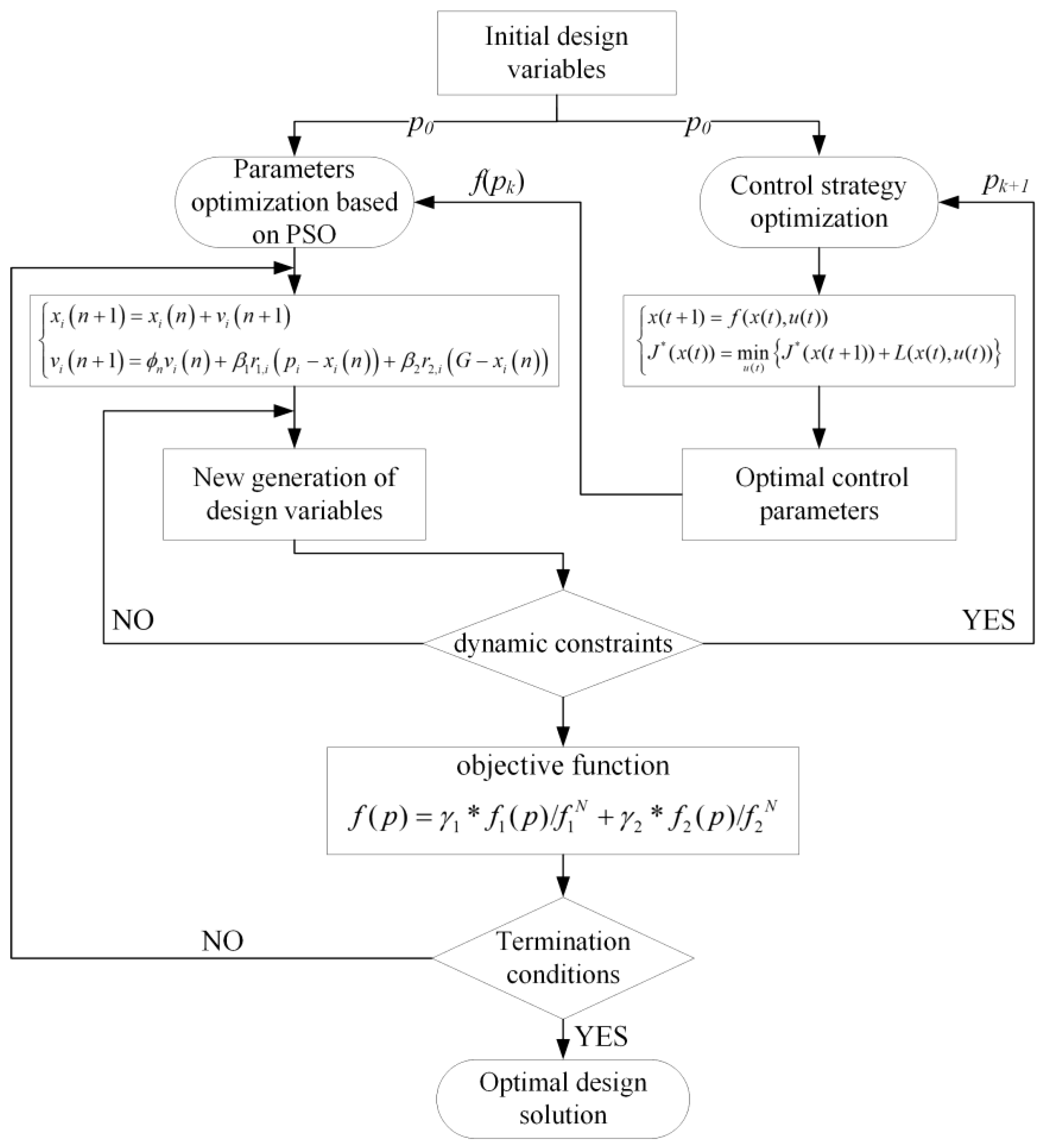
2.3.3. Optimization Process

To achieve superior energy efficiency while ensuring dynamic performance, we propose a two-layer hybrid optimization method based on the Particle Swarm Optimization (PSO) algorithm and Dynamic Programming (DP) algorithm for the DMCDS. This method effectively addresses the coupled effect of component parameters and system control. The two optimization layers work in conjunction to optimize the critical component parameters of the DMCDS. In the outer layer, the PSO algorithm optimizes the component parameters using the optimal control parameters provided by the inner layer. In the inner layer, the DP algorithm is applied to determine the optimal control parameters based on the component parameters given by the outer layer. This comprehensive approach enables global optimization of both component parameters and system control. The optimization process is visually illustrated in Figure 6.

3. Results and Discussion

This section provides an overview of the Dual-Motor Coupled Drive System (DMCDS) parameter optimization results achieved through the two-layer hybrid optimization method, while highlighting the differences in energy-economic efficiency between pre-optimization and post-optimization. In this study, the DMCDS was specifically designed for urban SUVs, and the China light-duty vehicle test cycle and worldwide harmonized light-duty vehicles test cycles (CLTC and WLTC) were employed as the optimized driving cycles. Therefore, the vehicle speed over the driving cycles is shown in Figure 7.
Under these two driving cycles, the component parameters of the DMCDS were optimized using the two-layer hybrid optimization approach, and the optimized parameters are listed in Table 4. A comparative analysis was conducted, which resulted in comparing the optimized configuration with the prototype configuration that utilized two identical baseline motors.
Compared to the prototype scheme, the optimized motors (EM_S and EM_R) exhibit increased rated speeds and reduced peak torques. Consequently, the motor’s constant power region shifts to higher speeds, accompanied by an expanded constant torque region. These enhancements significantly contribute to elevated operational load rates for both motors, improving the utilization of the high-efficiency operational range. Furthermore, the increase in the planetary gear ratio (k) leads to a higher proportion of output power from EM_R and amplifies the output torque of EM_S, thus elevating the operational efficiency during high-speed, high-power and low-speed, high-torque conditions, fully leveraging the advantages of the DMCDS for efficient operation across various modes.
In contrast, the prototype scheme merely aligns with extreme load conditions of the vehicle, neglecting the critical match between the motor’s high-efficiency range and the driving cycles. This oversight increases the probability of the motor operating in low-load and low-efficiency regions, affecting the driving range of the electric vehicle.
To explore the effects of the two-layer hybrid optimization method on the energy-economic efficiency of the DMCDS, this study conducted a comparative analysis of three drive system schemes under the same vehicle parameters and driving cycle conditions. The three schemes include the Single Motor Drive System (SMDS), the DMCDS prototype scheme (DMCDS-pro), and the optimized DMCDS scheme (DMCDS-opt). The primary parameters of the SMDS can be found in Table 5. It is worth noting that the efficiency map of the motor in SMDS has the same shape as the baseline motor. To attain the optimal economic efficiency for the SMDS, we adopted the enumeration method for the gear ratio optimization.
Figure 8 illustrates the distribution of operating points for the motors in the three drive system configurations. It is evident that, compared to SMDS, both DMCDS-pro and DMCDS-opt have a higher number of operational points located in the high-efficiency region for motors EM_S and EM_R. This indicates the advantage of the dual-motor coupled drive system in achieving efficient operation through coordinated control in various modes. When comparing the operational point distribution of DMCDS-pro and DMCDS-opt, the optimized DMCDS demonstrates a greater number of operational points in the high-efficiency region. This can be attributed to the increase in rated speed and decrease in peak torque of the two motors, resulting in higher load rates for both motors. Consequently, the utilization efficiency of the high-efficiency region for the motors is enhanced, so the DMCDS-opt should have higher system efficiency in this case.
The average drive efficiency (ADE) was adopted as one of the evaluation indicators for assessing the system economic performance in this work. For a given driving cycle, the system drive efficiency is represented as
η ADE = 0 t P w P ele d t
where ηADE is the average drive efficiency and Pw is the vehicle demand power.
Figure 9 illustrates the time-varying drive efficiency of the three propulsion systems. The findings reveal that the SMDS has the lowest efficiency, followed by DMCDS-pro, which exhibits an average efficiency 1.75% higher than that of SMDS. Significantly, DMCDS-opt displays the highest average efficiency, exceeding DMCDS-pro by 2.5%.
Compared to SMDS, DMCDS-pro, which employs two identical motors, facilitates adaptation to varying vehicle speeds and loads through three driving modes. Moreover, the DMC mode enables continuous speed regulation, thereby enhancing motor operating efficiency. Consequently, DMCDS-pro exhibits a higher average drive efficiency compared to SMDS, which relies on a single motor and a two-gear transmission. However, the parameter matching of DMCDS-pro is based on vehicle performance indicators, without considering the alignment of the motor’s high-efficiency range with the vehicle operating conditions. As a result, the utilization efficiency of the high-efficiency region for the two motors is relatively low.
Conversely, DMCDS-opt, featuring two motors with different efficiency characteristics, establishes three high-efficiency regions within the drive system. This design enhances the utilization efficiency of the motor high-efficiency regions and contributes to reducing energy consumption.
The high-efficiency region utilization and electricity consumption were adopted as another two economic evaluation indicators in this study. The indicator values for the three drive system schemes were obtained through simulations and are presented in Table 6.
The results indicate that the utilization efficiency of the high-efficiency region in the dual-motor coupled drive configuration was significantly superior to SMDS, resulting in SMDS exhibiting the highest electricity consumption (18.18 kWh/100 km). In contrast, DMCDS-pro and DMCDS-opt demonstrated reductions in electricity consumption of 3.3% and 6.8%, respectively. It is evident that DMCDS-opt exhibited a remarkable increase in high-efficiency region utilization after optimization, resulting in reduced electricity consumption. In conclusion, the DMCDS achieves a higher efficiency through the synergistic optimization of component parameters and system control, effectively enhancing the driving range.

4. Conclusions

In order to enhance the energy utilization efficiency and extend the driving range of electric vehicles, a dual-motor coupled drive system with a simple structure is proposed, and a dynamic mathematical model is established to analyze the power flow characteristics under different driving modes. Considering the interdependence between the optimization of component sizes and the system coordinated control in the dual-motor coupled drive system, this paper proposes a two-layer hybrid optimization approach. In the outer layer, a multi-objective particle swarm algorithm is employed to optimize the component sizes. Meanwhile, in the inner layer optimization, the given feasible component parameters from the outer layer are subjected to the DP algorithm to identify the optimal control parameters. The primary findings of this paper are summarized as follows:
(1)
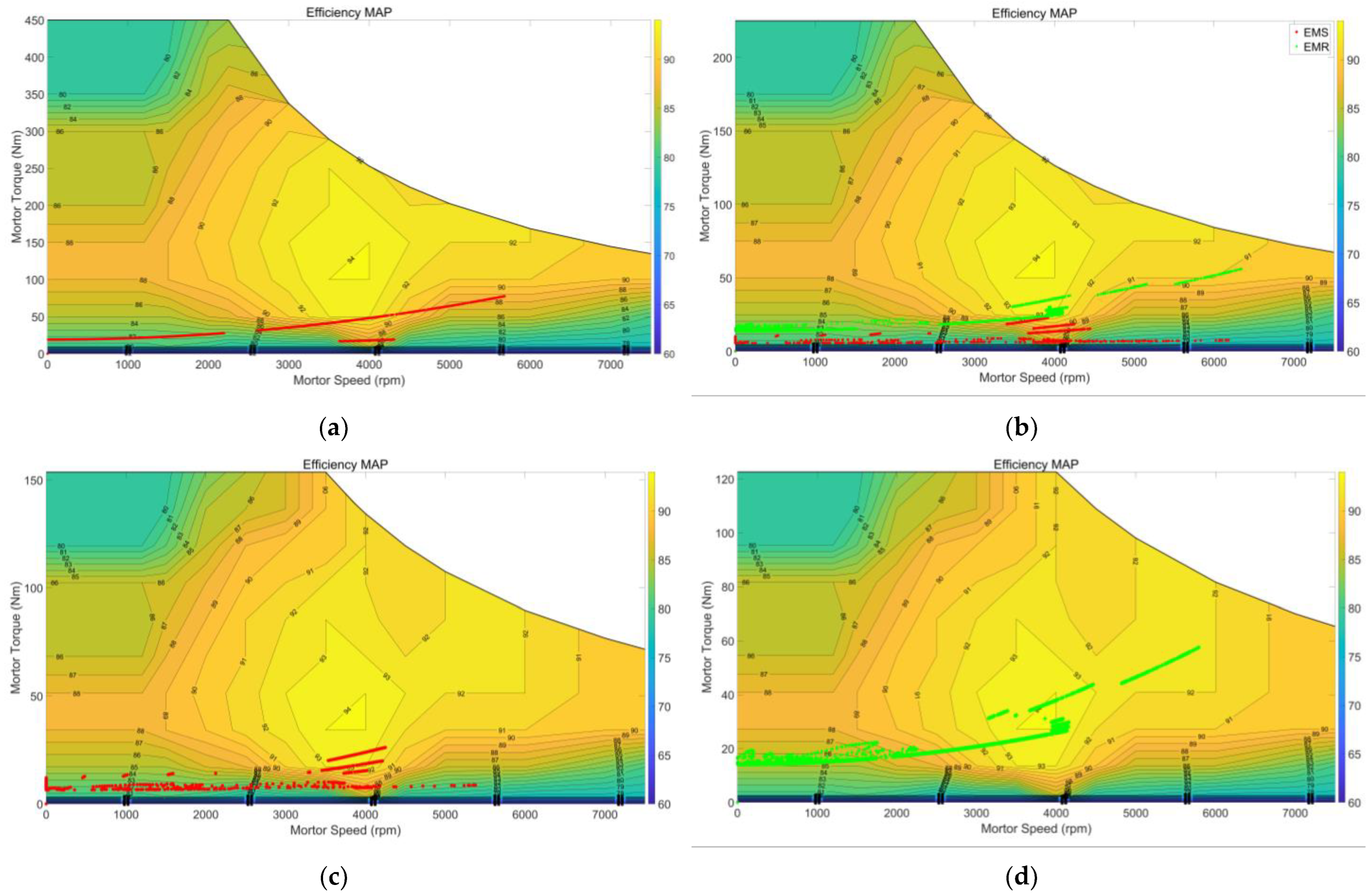
The selection of motor parameters and gear ratios exerts a substantial influence on the power losses and drive efficiency of the system. While keeping the system maximum output power unchanged, adjustments to the rated power, rated speed, and gear ratios can enhance the utilization efficiency of the high-efficiency region and effectively reduce electrical energy consumption.
(2)
The optimized motors exhibit an increase in rated speed and a decrease in peak torque, resulting in a substantial improvement in the utilization efficiency of the high-efficiency region. Compared to the prototype scheme, motors EM_R and EM_S experience an increase of 45% and 48%, respectively. Moreover, the optimized DMCDS achieves an average drive efficiency 2.5% and 4.2% higher than that of DMCDS-pro and SMDS, respectively, leading to DMCDS-opt possessing the lowest energy consumption of 16.95 kWh/100 km.

Author Contributions

Conceptualization, T.L.; methodology, T.L. and N.Z.; software, T.L.; validation, T.L. and X.G.; formal analysis, T.L.; investigation, D.P.; data curation, T.L.; writing—original draft preparation, T.L.; writing—review and editing, T.L. and N.Z.; supervision, D.P.; project administration, T.L. All authors have read and agreed to the published version of the manuscript.

Funding

This research was supported by China research project for fundamental product innovation (K23F024).

Data Availability Statement

Not applicable.

Conflicts of Interest

The authors declare no conflict of interest.

References

  1. Smith, W.J. Can EV (electric vehicles) address Ireland’s CO2 emissions from transport? Energy 2010, 35, 4514–4521. [Google Scholar] [CrossRef]
  2. Nunes, P.; Farias, T.; Brito, M.C. Enabling solar electricity with electric vehicles smart charging. Energy 2015, 87, 10–20. [Google Scholar] [CrossRef]
  3. Chopra, S.; Bauer, P. Driving range extension of EV with on-road contactless power transfer—A case study. IEEE Trans. Indust. Electron. 2013, 60, 329–338. [Google Scholar] [CrossRef]
  4. Li, Z.; Khajepour, A.; Song, J. A comprehensive review of the key technologies for pure electric vehicles. Energy 2019, 182, 824–839. [Google Scholar] [CrossRef]
  5. Walker, P.D. Modelling, Simulations, and Optimisation of Electric Vehicles for Analysis of Transmission Ratio Selection. Adv. Mech. Eng. 2013, 5, 1–13. [Google Scholar] [CrossRef]
  6. Kamachi, M.; Miyamoto, H.; Sano, Y. Development of power management system for electric vehicle ‘i-MiEV’. In Proceedings of the 2010 International Power Electronics Conference, Sapporo, Japan, 21–24 June 2010; pp. 2949–2955. [Google Scholar] [CrossRef]
  7. de Santiago, J. Electrical Motor Drivelines in Commercial All-Electric Vehicles: A Review. IEEE Trans. Veh. Technol. 2012, 61, 475–484. [Google Scholar] [CrossRef]
  8. Wu, J.; Liang, J.; Ruan, J.; Zhang, N.; Walker, P.D. Efficiency comparison of electric vehicles powertrains with dual motor and single motor input. Mech. Mach. Theory 2018, 128, 569–585. [Google Scholar] [CrossRef]
  9. Zhang, C.; Zhang, S.; Han, G.; Liu, H. Power Management Comparison for a Dual-Motor-Propulsion System Used in a Battery Electric Bus. IEEE Trans. Ind. Electron. 2017, 64, 3873–3882. [Google Scholar] [CrossRef]
  10. Hu, J.; Zu, G.; Jia, M.; Niu, X. Parameter matching and optimal energy management for a novel dual-motor multi-modes powertrain system. Mech. Syst. Signal Process. 2019, 116, 113–128. [Google Scholar] [CrossRef]
  11. Tseng, S.; Tseng, C.; Liu, T.; Chen, J. Wide-range adjustable speed control method for dual-motor drive system. IET Electr. Power Appl. 2015, 9, 107–116. [Google Scholar] [CrossRef]
  12. Holdstock, T.; Sorniotti, A.; Everitt, M.; Bertolotto, S. Energy consumption analysis of a novel four-speed dual motor drivetrain for electric vehicles. In Proceedings of the 2012 IEEE Vehicle Power and Propulsion Conference 2012, Seoul, Republic of Korea, 9–12 October 2012; pp. 295–300. [Google Scholar] [CrossRef]
  13. Xu, L.; Ouyang, M.; Li, J.; Yang, F.; Lu, L.; Hua, J. Optimal sizing of plug-in fuel cell electric vehicles using models of vehicle performance and system cost. Appl. Energy 2013, 103, 477–487. [Google Scholar] [CrossRef]
  14. Vagg, C.; Akehurst, S.; Brace, C.J. Stochastic dynamic programming in the real-world control of hybrid electric vehicles. IEEE Trans. Control Syst. Technol. 2016, 24, 853–866. [Google Scholar] [CrossRef]
  15. Kim, N.; Cha, S.W.; Peng, H. Optimal equivalent fuel consumption for hybrid electric vehicles. IEEE Trans. Control Syst. Technol. 2012, 20, 817–825. [Google Scholar] [CrossRef]
  16. Scordia, J.; Desbois-Renaudin, M.; Trigui, R.; Jeanneret, B.; Badin, F. Global optimisation of energy management laws in hybrid vehicles using dynamic programming. Int. J. Veh. Des. 2005, 39, 349–367. [Google Scholar] [CrossRef]
  17. Sundström, O.; Ambühl, D.; Guzzella, L. On implementation of dynamic programming for optimal control problems with final state constraints. Oil Gas. Sci. Technol. Rev. Inst. Fr. Pétrole 2010, 65, 91–102. [Google Scholar] [CrossRef]
  18. Wu, J.; Zhang, C.H.; Cui, N.X. PSO algorithm-based parameter optimization for HEV powertrain and its control strategy. Int. J. Automot. Technol. 2008, 9, 53–59. [Google Scholar] [CrossRef]
  19. Ebbesen, S.; Dönitz, C.; Guzzella, L. Particle swarm optimisation for hybrid electric drive-train sizing. Int. J. Veh. Des. 2012, 58, 181–199. [Google Scholar] [CrossRef]
  20. Zeng, X.H.; Wang, Z.W.; Song, D.F. Parameter Optimization of Dual-mode Power-split Hybrid Electric Bus Based on MIGA Algorithm. J. Mech. Eng. 2020, 56, 98–105. [Google Scholar] [CrossRef]
  21. Nuesch, T.; Ott, T.; Ebbesen, S.; Guzzella, L. Cost and fuel-optimal selection of HEV topologies using particle swarm optimization and dynamic programming. In Proceedings of the 2012 American Control Conference, Montréal, QC, Canada, 27–29 June 2012. [Google Scholar] [CrossRef]
  22. Bonnans, J.F.; Guilbaud, T.; Ketfi-Cherif, A. Parametric Optimization of Hybrid Car Engines. Optim. Eng. 2004, 5, 395–415. [Google Scholar] [CrossRef]
  23. Wen, C.; Zhang, S.; Xie, B.; Song, Z.; Li, T.; Jia, F.; Han, J. Design and verification innovative approach of dual-motor power coupling drive systems for electric tractors. Energy 2022, 247, 1–22. [Google Scholar] [CrossRef]
  24. Bayrak, A.E.; Kang, N.; Papalambros, P.Y. Decomposition-based design optimization of hybrid electric powertrain architectures: Simultaneous configuration and sizing design. J. Mech. Des. 2016, 138, 071405. [Google Scholar] [CrossRef]
  25. Landolfi, E.; Minervini, F.J.; Minervini, N.; De Bellis, V.; Malfi, E.; Natale, C. Integration of a Model Predictive Control with a Fast Energy Management Strategy for a Hybrid Powertrain of a Connected and Automated Vehicle. World Electr. Veh. J. 2021, 12, 159. [Google Scholar] [CrossRef]
  26. Coppola, A.; De Tommasi, G.; Motta, C.; Petrillo, A.; Santini, S. Double-layer control architecture for motion and torque optimisation of autonomous electric vehicles. Transp. Res. Interdiscip. Perspect. 2023, 21, 1–15. [Google Scholar] [CrossRef]
  27. Fathy, H.K.; Reyer, J.A.; Papalambros, P.Y.; Ulsoy, A.G. On the coupling between the plant and controller optimization problems. In Proceedings of the American Control Conference 2001, Arlington, VA, USA, 25–27 June 2001; pp. 1864–1869. [Google Scholar] [CrossRef]
  28. Fang, L.C.; Qin, S.Y.; Xu, G. Simultaneous optimization for hybrid electric vehicle parameters based on multi-objective Genetic Algorithms. Energies 2011, 4, 532–544. [Google Scholar] [CrossRef]
  29. Zhuang, W. Optimal Design and Mode Shift Control of Multi-mode Hybrid Electric Vehicles. Ph.D. Thesis, Nanjing University of Science & Technology, Nanjing, China, 2017. [Google Scholar]
  30. Nguyen, C.T.; Walker, P.D.; Zhou, S.; Zhang, N. Optimal sizing and energy management of an electric vehicle powertrain equipped with two motors and multi-gear ratios. Mech. Mach. Theory 2022, 167, 104513. [Google Scholar] [CrossRef]
  31. Pennestrì, E.; Mariti, L.; Valentini, P.; Mucino, V. Efficiency evaluation of gearboxes for parallel hybrid vehicles: Theory and applications. Mech. Mach. Theory 2012, 49, 157–176. [Google Scholar] [CrossRef]
Figure 1. Schematic diagram of DMCDS. 1. EM_S; 2. EM_R; 3. B1; 4. B2; 5. ring gear; 6. planetary gear mechanism; 7. main reduction gear; 8. differential mechanism.
Wevj 14 00282 g001
Figure 2. Equivalent lever model in M1S mode. The red line in the figure represents the lever and the green line represents the power flow.
Wevj 14 00282 g002
Figure 3. Equivalent lever model in M1R mode. The red line in the figure represents the lever and the green line represents the power flow.
Wevj 14 00282 g003
Figure 4. Equivalent lever model in DMC mode. The red line in the figure represents the lever and the green line represents the power flow.
Wevj 14 00282 g004
Figure 5. Efficiency map of motor EMB.
Wevj 14 00282 g005
Figure 6. Optimization process of two-layer hybrid optimization method.
Wevj 14 00282 g006
Figure 7. Optimized driving cycles: (a) CLTC-P and (b) WLTC.
Wevj 14 00282 g007
Figure 8. (a) Motor working points in SMDS; (b) working points of motors in DMCDS-pro; (c) working points of EM_S in DMCDS-opt; (d) working points of EM_R in DMCDS-opt.
Wevj 14 00282 g008
Figure 9. Efficiency of driving system in CLTC and WLTC.
Wevj 14 00282 g009
Table 1. System operation status.
Working StatesDriving ModesM1M2B1B2
Park/NeutralN/P
Driving statesM1S
M1R
DMC
● signifies the activation of the motor or engagement of the brake, while ○ denotes the deactivation of the motor or disengagement of the brake.
Table 2. Basic parameters of the vehicle.
ParameterMeaningValue
ms (kg)Mass of vehicle1949
Af (m2)Frontal area 2.66
CDAir resistance coefficient0.4
frTire rolling friction coefficient0.015
rw (m)Tire radius 0.343
vmax (km/h)Maximum velocity150
tacc (s)0–100 km/h acceleration time9
Table 3. Range of parameters to be optimized.
ParameterLower LimitUpper Limit
Rated power of EM_S (kW)3060
Rated speed of EM_S (r/min)25004000
Rated power of EM_R (kW)3060
Rated speed of EM_R (r/min)25004000
Planetary gear ratio1.54
Final drive ratio46.5
Table 4. Comparison of component parameters.
Optimization ParameterOptimized Parameter ValuePrototype Parameter Value
Rated power of EM_S (kW)33.532
Rated speed of EM_S (r/min)35002250
Rated power of EM_R (kW)31.532
Rated speed of EM_R (r/min)40002250
Planetary gear ratio2.261.86
Final drive ratio5.154.93
Table 5. Parameters of SMDS.
ParameterValue
Rated power of motor (kW)64
Peak power of motor (kW)106
Rated speed of motor (r/min)2250
First gear ratio3.27
Second gear ratio1.98
Final drive ratio2.826
Table 6. Economic evaluation indicators.
SchemesSMDSDMCDS-proDMCDS-opt
Indicator
High-efficiency region utilization
(efficiency > 90%)
6.6%EM_R 30.2%EM_R 43.8%
EM_S 8.6%EM_S 12.8%
Electricity consumption (kWh/100 km)18.1817.5816.95
Disclaimer/Publisher’s Note: The statements, opinions and data contained in all publications are solely those of the individual author(s) and contributor(s) and not of MDPI and/or the editor(s). MDPI and/or the editor(s) disclaim responsibility for any injury to people or property resulting from any ideas, methods, instructions or products referred to in the content.

