Article

Novel Hybrid Thermal Management System for High-Power Lithium-Ion Module for Electric Vehicles: Fast Charging Applications

1
Research Group MOBI—Mobility, Logistics and Automotive Technology Research Centre, Vrije Universiteit Brussel, Pleinlaan 2, 1050 Brussels, Belgium
2
Flanders Make, 3001 Heverlee, Belgium
*
Author to whom correspondence should be addressed.
World Electr. Veh. J. 2022, 13(5), 86; https://doi.org/10.3390/wevj13050086
Submission received: 30 March 2022 / Revised: 28 April 2022 / Accepted: 5 May 2022 / Published: 11 May 2022

Abstract

:
Lithium-ion capacitors (LiC) are hybrid energy storage systems (ESS) combining the advantages of lithium-ion batteries and electric double-layer capacitors, including longer lifetime, high power, and energy densities. LiCs are popular for high-power applications where fast charge and discharge driving profiles are demanded from electric vehicles (EV). However, LiCs generate excess heat when they are exposed to fast charging/discharging profiles. Therefore, a robust thermal management system (TMS) is crucial, in order to ensure reliable operation. In this study, a novel hybrid TMS based on air-cooling system assisted phase change materials (PCM), heat pipes, and a heat sink is proposed for an LiC module under a 150 A continuous current profile. A very thin aluminum heat sink and flat copper heat pipes were added to the PCM to increase its thermal conductivity. An experimental test bench of the proposed TMS was developed, and the temperature distribution of the module for each of the individual LiC cells was studied. The maximum temperature of the module under natural convection, when there was not any cooling system, reached almost 59.8 °C. The experimental results showed that after using the proposed hybrid TMS, the hottest cell reached 36.18 °C while the coldest cell reached 35.54 °C. Therefore, 39.5% improvement could be seen during the whole charge and discharge process after 3000 s. Moreover, the temperature difference within the module, of four LiCs, was around 0.64 °C, which was exceptional.

1. Introduction

Nowadays, global warming and the usage of fossil fuels are at the worldwide center of attention [1]. The transportation industry is one of the main sectors which is highly connected to fossil fuels [2]. Therefore, electric vehicles (EVs) and hybrid electric vehicles (HEVs) are the most appropriate substitutes, with very low fuel consumption and emission [3]. Lithium-ion (Li-ion) batteries are classified as a reliable option for EVs and HEVs due to their features [4]. Nevertheless, their chemistry is not suitable for high-current profiles [5]. Therefore, lithium-ion capacitors (LiCs) have been introduced to the market [6], which have the benefits of Li-ion batteries and electric double-layer capacitors (EDLC) [7]. Thus, LiCs have the high power and high energy densities, which makes the LiC technology a suitable applicant for high-current profiles [8]. However, despite great potential, LiCs generate heat during the process in high-current profiles [9]. Thermal runaway and non-temperature uniformity damage the LiCs and affect their performance and lifetime [10]. Thus, their heat generation needs to be controlled by a proper thermal management system (TMS) [11,12]. TMS is an inevitable part of each electric and hybrid vehicle to ensure safety and reliability [13]. Many studies evaluated the effect of different thermal management systems on LiC and Li-ion battery cells [14,15]. The cooling systems are classified into active, passive, and hybrid cooling systems [16,17].
Air cooling is a common active cooling system because of the simple structure and low cost [18,19,20]. Karimi, et al. [21] experimentally and numerically designed a novel air cooling system for an LiC module consisting of ten cells in series. They investigated the effect of air velocity, spacing, inlet, and outlet position for the module in 1400 s. Behi, et al. [22] experimentally studied the effect of air-cooling on LTO cells under fast discharging. They considered the performance of the cooling system in different inlet velocities and ambient temperatures. However, air cooling is not a promising cooling method for the high ambient temperature and emergency conditions [23].
Liquid cooling systems are capable active cooling methods that are trustable in high current applications [24,25]. A mixture of water and ethylene glycol, or oil, can be used as a working fluid for this cooling method. Karimi, et al. [26] built a compact liquid cooling system for high-power LiC. They measured the temperature of the LiC under the natural convection and liquid-based cooling system, which reached 55.7 °C and 32.6 °C, respectively. Behi, et al. [27] numerically studied the effect of side liquid cooling on an LTO battery module consisting of 15 cells. They found the liquid cooling system decreased the maximum temperature of the module by 29.9%. Nonetheless, liquid cooling suffers high costs, high power, and liquid leakage. Akbarzadeh, et al. [28] investigated a novel liquid cooling system for a high energy battery module with PCM, for which 30% lower power consumption has been achieved.
Phase change material (PCM) is classified as a passive cooling system with no energy usage [29,30]. Phase change-based cooling systems can potentially control the temperature increase within a battery cell/module [31]. Karimi, et al. [32] considered the cooling effect of PCM and aluminum mesh for an LiC module. They found that the combination of the PCM and aluminum mesh decreased the maximum temperature of the module by 20%. Behi, et al. [33] designed a PCM-assisted heat pipe thermal management system for LTO cells under fast discharging. They discovered that the passive cooling system had a remarkable effect on cell temperature. They found that the cell temperature experienced a 40.7% reduction under the 8C discharging process. In comparison, PCM cooling methods are more energy-efficient; nevertheless, they suffer low thermal conductivity and reliability for large cooling loads. In another article, Karimi, et al. [34] experimentally enhanced the thermal properties of a PCM by adding graphite.
The heat pipe, fin, metal mesh, and heat sink are other examples of passive cooling systems [35,36,37]. Karimi, et al. [38] experimentally studied the cooling effect of a TMS consisting of heat pipes and PCM for an LiC cell under the current rate of 150 A. They found that the heat pipe and PCM-assisted heat pipe cooling system decreased the temperature of the cell by 15% and 35% respectively. Behi, et al. [39] numerically considered the performance of a heat pipe air-based cooling system on a cylindrical battery module. They investigated the effect of cell spacing, ambient temperature, and inlet velocity on the battery module. However, heat pipes suffer from complex design, gravity, and high cost.
As noted, each thermal management solution has some drawbacks that impact the performance and efficiency of the cooling systems [40]. Hybrid cooling systems provide the ability to compensate for the drawbacks of the cooling methods, and achieve the maximum efficiency of the cooling systems [41]. In this study, a novel methodology is proposed based on a hybrid TMS which combines an air-cooling system, paraffin PCM, thin flat heat pipes, and a thin layer of heat sink. Experimental tests were performed, to study the performance and robustness of the proposed hybrid HPA-TMS. The tests were conducted under the harsh driving profile, including fast charges and discharges for 3000 s with 150 A current rate. The design target of this study was to reduce the maximum temperature of the LiC module under high current rates, while the temperature uniformity of the module was minimized. This was in order to help extend the lifetime of the module, and to avoid hotspots on individual cells. The LiC should work under 40 °C regarding the thermal limits announced by the manufacturer (JSR Company, ULTIMO). Therefore, the main aim was to keep the absolute temperature of the module below 40 °C, and at the same time, decrease the temperature difference between the coldest cell and the hottest cell.

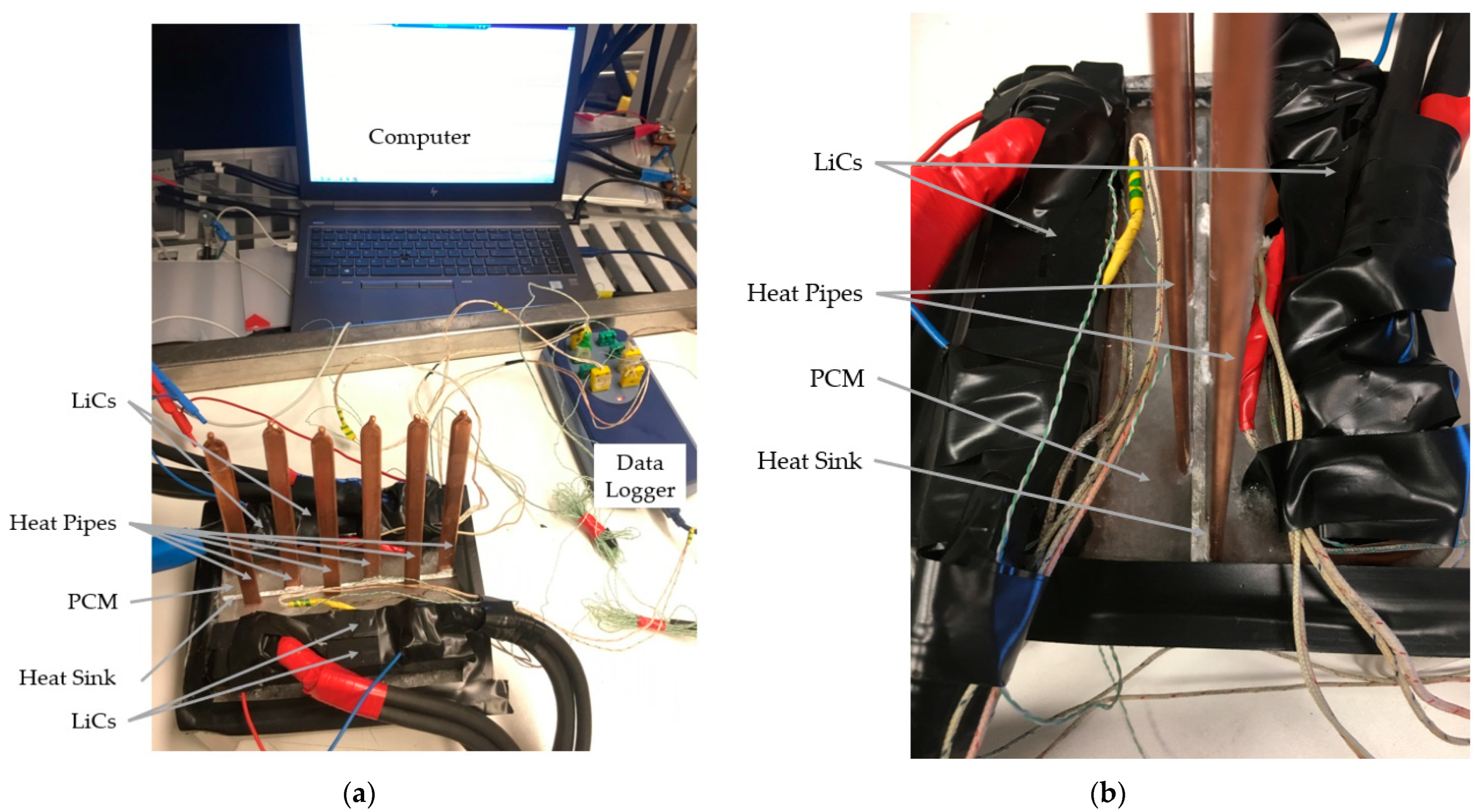
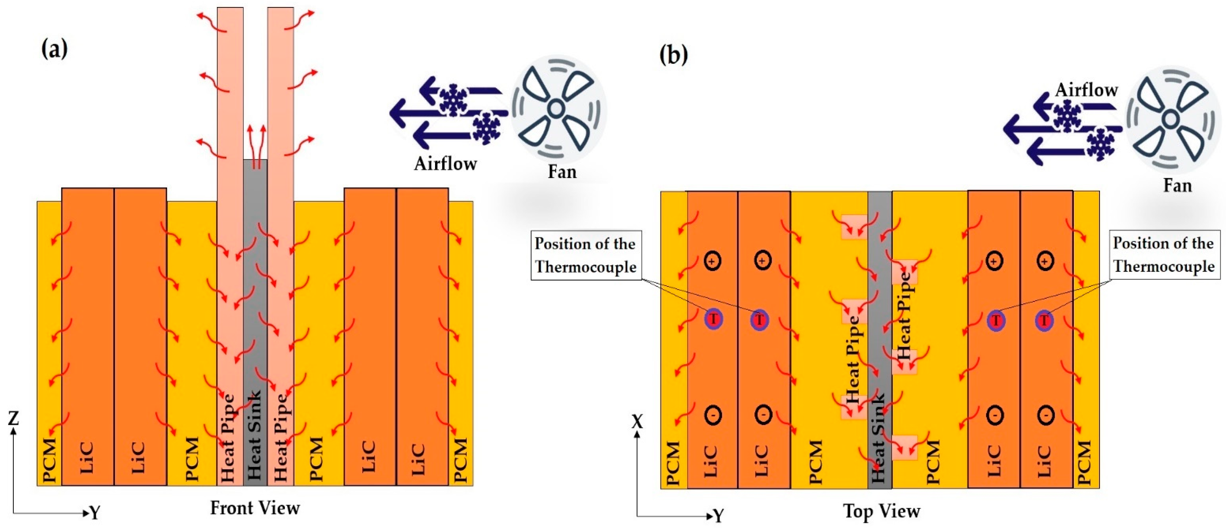
2. Design of Hybrid HPA-TMS

As shown in Figure 1, the proposed hybrid HPA-TMS consisted of four prismatic lithium-ion capacitors (LiC), a paraffin phase change material (PCM), six flat heat pipes, and a fan for air cooling. A data logger and K-type thermocouples were responsible for monitoring the temperature evolution during the cycling profile. The battery tester and battery cycler were responsible for cycling the module.
A computer was linked to the data logger and the tester, to get the voltage, current, and temperature of the cells, based on a continuous 150 A charge and discharge current rate. Before the commencement of the tests, the PCM was mounted inside the climate chamber, with a temperature more than the melting temperature of the PCM. Then, the melted PCM was poured inside the PVC container, with very low thermal conductivity (around 0.2 W/m·K) between the LiC cells. In addition, six flat heat pipes were stuck to the thin aluminum heat sink through a very tiny layer of thermal interface material (TIM). In this study, thermal grease with thermal conductivity of 8 W/m.K was selected to be the TIM. There were two LiC cells (dual-cells) on each side of the container, so that the module consisted of four LiCs. Each side of the dual-cells was covered with a 10 mm layer of PCM to absorb the heat loss of the module, and to release it to the ambient through the heat pipes and the aluminum heat sink. The process of absorbing/rejecting the heat loss of the module was a perfect method of making thermal insulation to avoid thermal runaway.
The flat heat pipes and the aluminum heat sink were the added secondary materials for increasing the very low thermal conductivity of the PCM. In this respect, a very thin layer of the aluminum heat sink was added between the dual-cells and the PCM, forming a sandwich structure. The top surface of the heat pipes was exposed to the airflow coming from the fan. Since the air loop was arranged outside of the LiC module, the complexity of the system was reduced greatly, which bespoke the feasibility of the proposed system as compared with the traditional system of having the air-cooling system inside the module.
The next stage was to again mount the PVC container full of melted PCM inside the climate chamber, at a constant temperature of 23 °C. This was to help the PCM solidify and reach 23 °C, which was the initial temperature for starting the experimental tests. After solidifying the PCM, the voltage and current cable were connected to the battery tester. The thermocouples were also connected to the LiC cells from one side and to the data logger from the other side. The test bench of the hybrid HPA-TMS was then ready for commencement of the cycling tests. The test profile was a continuous 150 A fast charging and discharging without any pause. Table 1 lists the specifications of the employed LiC cells, the flat heat pipes, the heat sink, the PCM, and the PVC container. Figure 2 exhibits the whole process of the generated heat absorption and removal by the proposed hybrid HPA-TMS. Temperature is one of the most vital parameters that affect the performance of LiCs [42,43] by causing irreversible effects, including accelerated aging [44], impurities production [45], and evaporation of solvent [46,47,48]. LiCs generate more heat with smaller ESR, since they have been used in high power applications under high current rates [49]. Therefore, the lifetime and performance of LiCs significantly depend on their working temperature. In this context, a robust TMS is quite essential to control the thermal behavior of LiCs [8].
As can be seen from Figure 2, the heat was generated inside the LiC cells in the module due to internal resistance and entropy change in the system, which were counted as reversible and irreversible heat sources. Then, the generated heat was absorbed by the PCM, but could be fully rejected to the ambient due to the low thermal conductivity of the paraffin PCM. Therefore, the combination of the heat pipes and the heat sink absorbed the ingested heat from the PCM. The heat sink and heat pipes together increased the heat dissipation rate from the module to the ambient.
Generally, each heat pipe had three sections including the evaporator section, the condenser section, and the adiabatic section. The stored heat inside the PCM was transferred to the aluminum heat sink, which was absorbed quickly by the heat pipes due to their evaporator section. Then, the heat loss was moved to the condenser section of the heat pipe, and escaped to the ambient through the airflow of the fan. The efficiency of the whole process of heat loss absorption and rejection was enhanced by this method, which improved the performance of the proposed thermal management system.

3. Governing Equations

3.1. Heat Transfer Model

In this work, uniform heat generation was considered for the LiC cell during charging and discharging continuous current rate [50]:
Q g e n = ( R I 2 I T L i C U T ) / V L i C
where Q g e n , R , I , T L i C , U T and V L i C denote the generated heat, resistance, current rate, temperature, entropy change, and volume of the LiC. The term I T L i C U T represents the heat loss caused by the electrochemical reaction inside the LiC, which can be considered as a constant value since its products were very low compared to the heat loss due to the resistance.
To model the heat transfer, the energy equation was utilized to get the temperature information of the LiC [51,52]:
ρ C p T t = · ( k T ) + Q g e n
where ρ denotes density, C p is the specific heat, and k represents the thermal conductivity.
For the PCM, the enthalpy-porosity method was used for the heat transfer and melting process. The momentum and continuity equations for the Newtonian incompressible molten PCM, which was considered as a laminar flow, is expressed as [53]:
ρ P C M t + · ( ρ P C M υ ) = 0
ρ P C M υ t + ρ P C M ( υ · ) υ = ρ P C M + μ 2 υ + S
where ρ P C M and υ are the density and velocity vector of the PCM. Moreover, the energy equation can be expressed as [54]:
ρ P C M H t + ρ P C M ( · υ H ) = k P C M ( 2 T )
S = A m u s h y ( 1 β ) 2 β 3 + ε υ
where k P C M and H denote the thermal conductivity and the enthalpy of the PCM. In addition, β represents the liquid volume fraction of the PCM, and ε = 0.001 . The constant ε is a decimal that helps the equation avoid being divided by zero. Lastly, A m u s h y denotes the constant of the mushy zone that was happening between the liquid and solid phases of the PCM. This constant reflects the melting behavior of the PCM, which was considered as 105.
For the enthalpy of the PCM, the sensible heat and the latent heat of fusion have been summed as follows:
H = h r e f + T r e f T C P C M d t + β L
where h r e f , T r e f , C P C M and L represent the reference enthalpy, reference temperature, specific heat of the PCM, and latent heat of fusion, respectively. Therefore, the liquid fraction of the PCM ( β ) was calculated as follows:
β = { 0   ,   T < T s ( T T s ) / ( T L T s ) ,   T s T T L 1 ,   T > T L
where T s and T L are the solid phase and liquid phase temperatures. In the equation, 0 means fully solid PCM and 1 means fully liquid PCM.
The parameters of the air-cooling system show that the airflow is laminar. Therefore, the energy, continuity, and momentum equations for the air cooling can be expressed as follows [21]:
ρ a i r t + · ( ρ a i r υ a i r ) = 0
where ρ a i r and υ a i r denote the density and flow rate of air, and:
( ρ a i r υ a i r ) t + · ( ρ a i r υ a i r . υ a i r ) = ρ a i r
( ρ a i r υ a i r T a i r ) t + · ( ρ a i r υ a i r C a i r T a i r ) = · ( k a i r T a i r )
where C a i r , k a i r , and T a i r represent the specific heat, thermal conductivity, and temperature of the air. For the heat pipe, the whole system of the used heat pipes was considered as a uniform thermal conductor, that had an equivalent thermal conductivity, which can be expressed as:
k h p =   Q h p l h p A h p Δ T h p
where k h p denotes the equivalent thermal conductivity of the heat pipes. Q h p , A h p and Δ T h p are the amount of heat that can be transferred by the heat pipes, the cross-sectional area, and the temperature difference between the condenser and evaporator sections, respectively. Also, l h p is the equivalent length of the heat pipe, that can be expressed as:
l h p = l c + l e 2 + l a
where l c , l e and l a denote the length of the condenser section, the evaporator section, and the adiabatic section, respectively. Therefore, the heat transfer equation of the heat pipe can be written as:
ρ h p C h p T h p t = · ( k h p T h p )

3.2. Initial Conditions and Boundaries

The initial temperature of T t e s t = 23 °C was considered for the experimental tests at t = 0 s. Therefore, T t e s t = T L i C = T P C M = T h p = T a i r = T a m b = T h s , in which T L i C ,   T P C M ,   T h p ,     T a i r ,   T a m b ,   T h s denote the temperature of LiC, PCM, heat pipe, airflow, ambient, and heat sink, respectively. There was an interface between the LiC and the PCM in the system. Thus, the boundary condition of this interface was considered as:
k L i C T n = k P C M T n
For the interface between the PCM and the heat pipes and heat sink:
k P C M T n = k h p T n k h s T n
For the interface between the heat sink, the heat pipe, and the air-cooling system:
k h s T n = k h p T n k a i r T n
Finally, for the interface between the heat pipe and the air-cooling system:
k h p T n = k a i r T n
where k L i C , k h p , k h s , k a i r , and k P C M denote the thermal conductivity of the LiC, the heat pipes, the heat sink, the airflow, and the PCM. Moreover, T n is the temperature gradient. The thermal resistance was negligible where each boundary was supposed to be an ideal boundary condition. Moreover, the boundary condition between the LiC module and the ambient is expressed as:
k L i C T L i C n = h ( T L i C T a m b )
where h denotes the heat transfer coefficient, which was considered as 13 W/m2·K in this work. Such a low heat transfer coefficient was assumed to be natural convection, since the tests were performed in a room with a constant temperature of 23 °C.

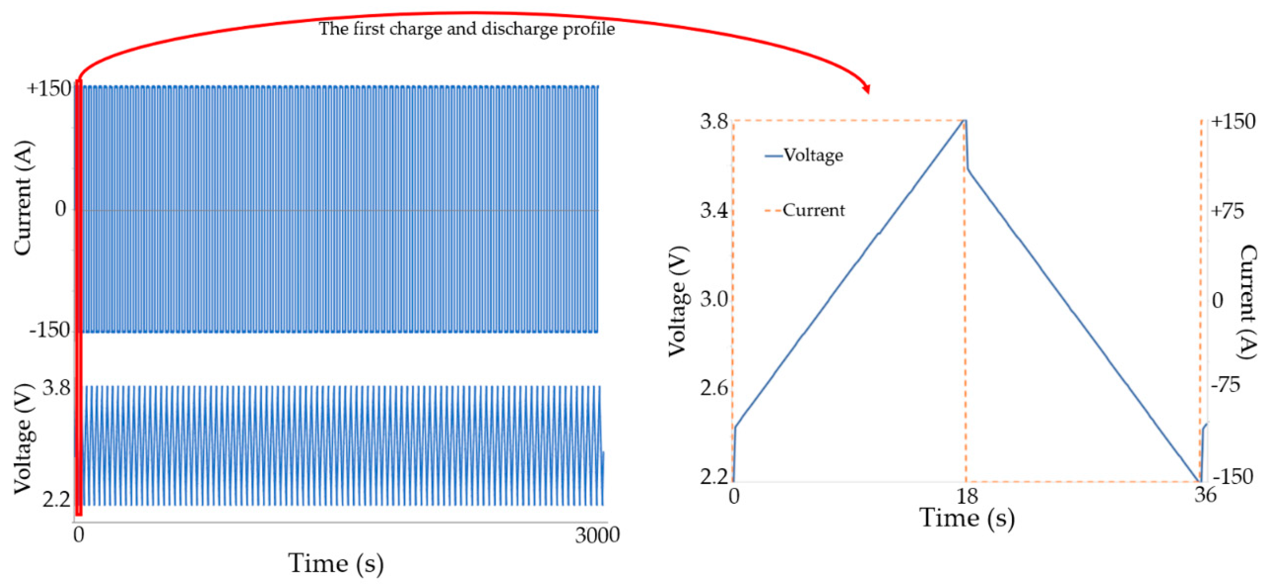
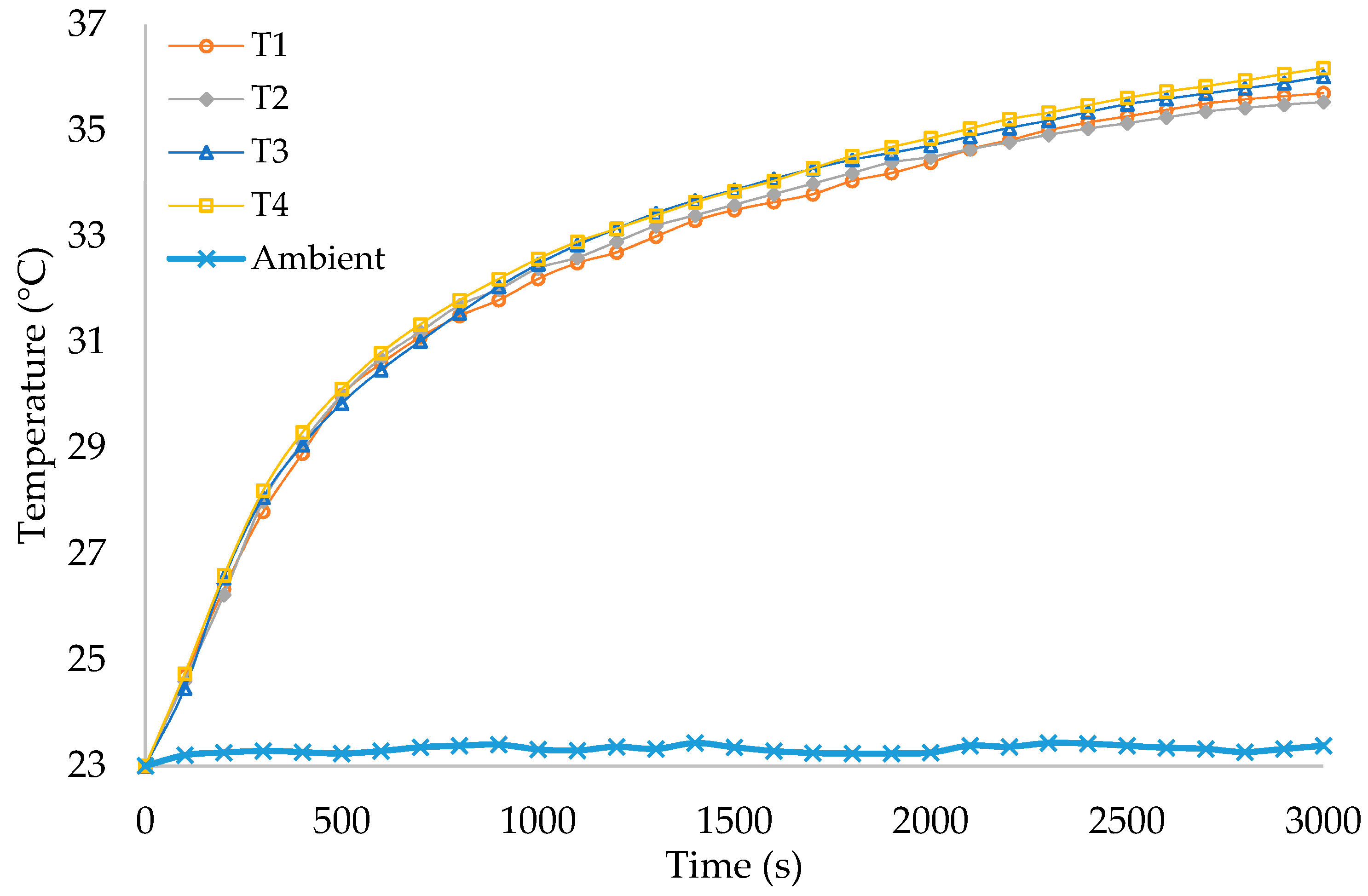
4. Results and Discussion

The experimental tests of the proposed HPA-TMS were conducted under a 150 A continuous cycling profile, where the current rate corresponded to the charge and discharge current that was applied to the cell. Figure 3 shows the current and voltage applied to the module. Using the electro-thermal model that had been developed in our previous works [55,56], the heat loss of the system under such a harsh driving cycle was calculated. The generated heat under the continuous 150 A current rate is exhibited in Figure 4. The generated heat of the LiC regarding its dimensions for a 150 A fast charging and fast discharging profile is listed in Table 2, which shows that the generated heat of the LiC was 3.5 times larger than the normal heat generation condition of LiBs [57].
To cycle the LiC module under a 150 A intense driving profile, a battery tester was used to acquire the data, by using a computer linked to the tester. This experimental test bench monitored the module’s current, voltage, and temperature, along with other parameters during testing. The battery tester handled the test’s definition, and the current rate’s value was implemented according to the cell requirements [58]. The cell was located inside the climate chamber to stabilize its initial temperature at 23 °C before the experimental test to investigate the cell’s temperature evolution. The charging and discharging of the cell was carried out utilizing the testers in which the cell was cycled by the continuous current rate of 150 A with a 3000 s current profile.
To calculate the error of the experiments, and to check the accuracy of the results, the Schultz and Cole method was employed for the uncertainty analysis, which can be expressed as [59,60]:
U R = [ i = 1 n ( R V I U V I ) 2 ] 1 / 2
where U V I denotes the error of every single factor and U R stands for total errors. The maximum uncertainty is expressed in percentage, which was calculated as 1.17%, which was perfect.
Four K-type thermocouples were used, such that one thermocouple was pasted on the top surface of each individual cell, to measure the maximum temperature of each cell, as can be seen in Figure 2b. The temperature difference between each cell of the module was determined by the surface temperatures. In this regard, the maximum temperature means the highest temperature value that a cell was able to obtain on its top surface, while the temperature difference refers to the temperature uniformity. Figure 5 exhibits the temperature evolution of the LiC module, based on the temperature of four cells and the ambient temperature that was monitored by the thermocouples and the data logger connected to the computer.
The ambient temperature was also recorded to check if the room temperature was kept constant at its initial temperature of 23 °C. Table 3 lists the maximum temperature of each individual cell within the module after cooling down by the hybrid HPA-TMS during 3000 s. As can be seen, the hottest cell reached 36.18 °C while the coldest cell reaches 35.54 °C. Therefore, during the whole charge and discharge process, the temperature difference within the module of four LiCs was around 0.64 °C, which was exceptional. LiC structure is made for heavy-duty applications, where high power is demanded. The performance of the proposed TMS is more evident when comparing the results with the thermal behavior of the module before using any TMS. The maximum temperature of the module is achieved under natural convection when there is not any TMS. The results show that, in this case, the maximum temperature of the module exceeded 59.8 °C, which is harmful for the lifetime of the module since the cycle life of the LiCs would be diminished. Comparing the temperature results of the system under natural convection, and the system after using the HPA-TMS, shows a reduction of 39.5% in the maximum temperature of the module. Therefore, under a high-power driving profile of 150 A charge and discharge without any rest, the proposed TMS works perfectly to ensure the safe and reliable operation of such technology.
The temperature evolution of the LiC, when only PCM is used as the TMS, has been reported in our previous work [61], and is not reported here to avoid redundancy. Likewise, the thermal behavior of the LiC using the same heat pipes has been reported in our previous work [62]. The results show that the maximum temperature of the LiC, employing only the PCM or only the heat pipe TMSs after 1400 s, reaches 40.8 °C and 48.8 °C, respectively. These results are for a single LiC cell. Nevertheless, for a module of four cells, the maximum temperature using only the PCM, or only the heat pipe, would be far higher. On the other hand, in the hybrid HPA-TMS, the maximum temperature of the hottest point in the module after 1400 s reached 33.6 °C, which was a 17.6% enhancement compared with the PCM, and a 31.1% improvement compared with the heat pipe TMS. Moreover, the hybrid HPA-TMS results prove that even with the double time, after 3000 s, the proposed hybrid system can fully control the maximum temperature of the module.
Another critical challenge for LiCs is the temperature non-uniformity that is the main reason for electrical imbalance and SoC mismatch among the module cells [63]. Therefore, special attention was given to designing a robust TMS to manage the temperature rise of the LiCs during high charging and discharging.
At the beginning of the test, the temperature of the module (all the LiC cells) rose sharply due to the electrochemical reactions inside the LiCs. However, the temperature difference within the cells of the module remained almost the same below 1 °C. In the case of testing the module with the same load profile under natural convection when there was not any TMS, the temperature difference between neighboring cells in the module was more than 7 °C. This trend proved that more than 85.7% improvement is achieved for the temperature uniformity when the hybrid HPA-TMS is employed.
In addition, the temperature of the LiC cells was recorded using IR images thanks to the thermal camera having an error of less than ±0.2 °C. As is illustrated in Figure 6, the maximum temperature of the LiC at the end of the cycling profile (3000 s) was around 36.9 °C, while the current cables reached more than 42 °C. The proposed HPA-TMS proves that combining the heat absorption ability of the PCM with a secondary material that can reject the stored heat of the PCM leads to the high performance of the TMS. This is because the very low thermal conductivity of the paraffin PCM is not able to release the absorbed heat. In this scenario, the PCM gets hotter and cannot reject the stored heat after reaching its evaporation point. Thus, at this point, the PCM is not able to receive the generated heat of the LiC module, which will result in accumulated temperature inside the system and thermal runaway.
On the other hand, if a secondary passive system is used to receive the stored heat of the PCM, the heat can be rejected to the environment easily. However, passive systems alone are not good candidates in high power applications where the heat convection coefficient is very low, and the flow is natural convection. In such conditions, the temperature of the module can be reduced, but not efficiently below the safe limit. Therefore, an active cooling system is required to increase the thermal performance and reject the accumulated heat of the system.
The used air-cooling system increases the heat transfer rate by enhancing the heat convection coefficient, and thereby enhancing the thermal performance. The module without any cooling system under natural convection reaches almost 59.8 °C; its lifetime will be reduced in such operating temperatures [62]. Comparing the results of the natural convection and the hybrid HPA-TMS shows that the proposed hybrid system has 39.5% efficiency, which is ideal.
The temperature of the heat pipes and the heat sink was monitored employing IR thermal camera images. Figure 7 depicts the temperature distribution of the system where the focus is on the heat pipes and the heat sink. As can be seen, the maximum temperature of the heat pipes after a 3000 s cycling profile reached almost 29.6 °C, meaning that a 6.6 °C increase happened inside the heat pipes.
The results prove that the maximum temperature of the module was negatively correlated with the temperature uniformity within the LiC module, as high thermal performance leads to a high dissipation rate, which resulted in higher temperature uniformity due to higher temperature difference between the neighboring cells in the module.

5. Conclusions

In this study, a novel hybrid TMS based on air cooling system assisted phase change materials (PCM), six flat heat pipes, and a thin aluminum heat sink was proposed for an LiC module under a 150 A continuous current profile. The heat sink and heat pipes were added to the PCM to increase its low thermal conductivity. The experimental test bench of the proposed system was developed, and the temperature distribution of the module for each of the individual LiC cells was studied. The experiments produced the following results:
  • The maximum temperature of the module under natural convection when there is not any cooling system reached almost 59.8 °C.
  • After using the proposed hybrid TMS, the hottest cell reached 36.18 °C while the coldest cell reached 35.54 °C. Therefore, a 39.5% improvement was seen during the whole charge and discharge process after 3000 s.
  • Using only PCM, the maximum temperature of a single cell reached 40.8 °C. Therefore, the HPA-TMS had a 17.6% better performance than the only PCM.
  • Using only heat pipe, the maximum temperature of a single cell reached 48.8 °C. Therefore, the HPA-TMS had 31.1% better performance than the only heat pipe.
The temperature difference within the module of four LiCs was around 0.64 °C, which was exceptional.

Author Contributions

Conceptualization, methodology, formal analysis, investigation, writing—original journal draft by D.K.; writing—review and editing by H.B.; supervision, writing—review and editing by J.V.M. and M.B. All authors have read and agreed to the published version of the manuscript.

Funding

This research received no external funding.

Institutional Review Board Statement

Not applicable.

Informed Consent Statement

Not applicable.

Data Availability Statement

Not applicable.

Acknowledgments

This research is based on work supported by JSR Micro NV and Flanders Make.

Conflicts of Interest

The authors declare no conflict of interest.

References

  1. Van Mierlo, J.; Berecibar, M.; El Baghdadi, M.; De Cauwer, C.; Messagie, M.; Coosemans, T.; Jacobs, V.A.; Hegazy, O. Beyond the State of the Art of Electric Vehicles: A Fact-Based Paper of the Current and Prospective Electric Vehicle Technologies. World Electr. Veh. J. 2021, 12, 20. [Google Scholar] [CrossRef]
  2. Danko, J.; Bugár, M.; Staňák, V. Energy Analysis of Hybrid Power Source during Vehicle Motion. Sci. Proc. Fac. Mech. Eng. 2011, 19, 30–35. [Google Scholar] [CrossRef]
  3. O’Keefe, M.; Bennion, K. A Comparison of Hybrid Electric Vehicle Power Electronics Cooling Options. In Proceedings of the 2007 IEEE Vehicle Power and Propulsion Conference (VPPC 2007), Arlington, TX, USA, 9–12 September 2007; pp. 116–123. [Google Scholar] [CrossRef] [Green Version]
  4. Khaleghi, S.; Karimi, D.; Beheshti, S.H.; Hosen, S.; Behi, H.; Berecibar, M.; Van Mierlo, J. Online health diagnosis of lithium-ion batteries based on nonlinear autoregressive neural network. Appl. Energy 2020, 282, 116159. [Google Scholar] [CrossRef]
  5. Behi, H.; Karimi, D.; Jaguemont, J.; Berecibar, M.; Van Mierlo, J. Experimental study on cooling performance of flat heat pipe for lithium-ion battery at various inclination angels. Energy Perspect. 2020, 1, 77–92. [Google Scholar]
  6. Naoi, K.; Ishimoto, S.; Miyamoto, J.-I.; Naoi, W. Second generation ‘nanohybrid supercapacitor’: Evolution of capacitive energy storage devices. Energy Environ. Sci. 2012, 5, 9363–9373. [Google Scholar] [CrossRef]
  7. Rajan, R.S.; Rahman, M. Lifetime Analysis of Super Capacitor for Many Power Electronics Applications. IOSR J. Electr. Electron. Eng. 2014, 9, 55–58. [Google Scholar] [CrossRef]
  8. Laadjal, K.; Cardoso, A.J.M. A review of supercapacitors modeling, SoH, and SoE estimation methods: Issues and challenges. Int. J. Energy Res. 2021, 45, 18424–18440. [Google Scholar] [CrossRef]
  9. Soltani, M.; Jaguemont, J.; Boninsegna, M.; Berckmans, G.; Abdel-monem, M. Thermal management system for a Lithium-ion Capacitor Module with air cooling strategy. In Proceedings of the International Electric Vehicle Symposium and Exhibition (EVS), Stuttgart, Germany, 9–11 October 2017; pp. 1–10. [Google Scholar]
  10. Berckmans, G.; Jaguemont, J.; Soltani, M.; Samba, A.; Boninsegna, M.; Omar, N.; Hegazy, O.; Van Mierlo, J.; Ronsmans, J. Lithium-Ion Capacitor—Optimization of Thermal Management from Cell to Module Level. In Proceedings of the IEEE Vehicle Power and Propulsion Conference (VPPC), Hangzhou, China, 17–20 October 2016; pp. 1–6. [Google Scholar] [CrossRef]
  11. Möller, S.; Karimi, D.; Vanegas, O.; El Baghdadi, M.; Kospach, A.; Lis, A.; Hegazy, O.; Abart, C.; Offenbach, Â.B.Â. Application Considerations for Double Sided Cooled Modules in Automotive Environment. 2020. Available online: https://ieeexplore.ieee.org/document/9097721 (accessed on 16 November 2020).
  12. Soltani, M.; Ronsmans, J.; Jaguemont, J.; Van Mierlo, J.; Bossche, P.V.D.; Omar, N. A Three-dimensional thermal model for a commercial lithium-ion capacitor battery pack with non-uniform temperature distribution. In Proceedings of the 2019 IEEE International Conference on Industrial Technology (ICIT), Melbourne, Australia, 13–15 February 2019; pp. 1126–1131. [Google Scholar] [CrossRef]
  13. Karimi, D.; Behi, H.; Jaguemont, J.; El Baghdadi, M.; Van Mierlo, J.; Hegazy, O. Thermal Concept Design of MOSFET Power Modules in Inverter Subsystems for Electric Vehicles. In Proceedings of the 2019 9th International Conference on Power and Energy Systems (ICPES), Perth, WA, Australia, 10–12 December 2019; pp. 1–6. [Google Scholar] [CrossRef]
  14. Soltani, M.; Ronsmans, J.; Kakihara, S.; Jaguemont, J.; van den Bossche, P.; Van Mierlo, J.; Omar, N. Hybrid Battery/Lithium-Ion Capacitor Energy Storage System for a Pure Electric Bus for an Urban Transportation Application. Appl. Sci. 2018, 8, 1176. [Google Scholar] [CrossRef] [Green Version]
  15. Nikolian, A.; Jaguemont, J.; de Hoog, J.; Goutam, S.; Omar, N.; Bossche, P.V.D.; Van Mierlo, J. Complete cell-level lithium-ion electrical ECM model for different chemistries (NMC, LFP, LTO) and temperatures (−5 °C to 45 °C)—Optimized modelling techniques. Int. J. Electr. Power Energy Syst. 2018, 98, 133–146. [Google Scholar] [CrossRef]
  16. Behi, H.; Behi, M.; Ghanbarpour, A.; Karimi, D.; Azad, A.; Ghanbarpour, M.; Behnia, M. Enhancement of the Thermal Energy Storage Using Heat-Pipe-Assisted Phase Change Material. Energies 2021, 14, 6176. [Google Scholar] [CrossRef]
  17. Karimi, D.; Behi, H.; Jaguemont, J.; Berecibar, M.; Van Mierlo, J. A refrigerant-based thermal management system for a fast charging process for lithium-ion batteries. In Proceedings of the International Conference on Renewable Energy Systems and Environmental Engineering, Brussels, Belgium, 18–20 July 2020; Global Publisher: Hershey, PA, USA, 2020; pp. 1–6. [Google Scholar]
  18. Karimi, D.; Behi, H.; Jaguemont, J.; Berecibar, M.; Van Mierlo, J. Optimized air-cooling thermal management system for high power lithium-ion capacitors. Energy Perspect. 2020, 1, 93–105. [Google Scholar]
  19. Karimi, D.; Behi, H.; Jaguemont, J.; Berecibar, M.; Van Mierlo, J. Investigation of extruded heat sink assisted air cooling system for lithium-ion capacitor batteries. In Proceedings of the International Conference on Renewable Energy Systems and Environmental Engineering, Brussels, Belgium, 18–20 July 2020; Global Publisher: Hershey, PA, USA, 2020; pp. 1–6. [Google Scholar]
  20. Behi, H.; Kalogiannis, T.; Patil, M.S.; Van Mierlo, J.; Berecibar, M. A New Concept of Air Cooling and Heat Pipe for Electric Vehicles in Fast Discharging. Energies 2021, 14, 6477. [Google Scholar] [CrossRef]
  21. Karimi, D.; Behi, H.; Akbarzadeh, M.; Van Mierlo, J.; Berecibar, M. A Novel Air-Cooled Thermal Management Approach towards High-Power Lithium-Ion Capacitor Module for Electric Vehicles. Energies 2021, 14, 7150. [Google Scholar] [CrossRef]
  22. Behi, H.; Behi, M.; Karimi, D.; Jaguemont, J.; Ghanbarpour, M.; Behnia, M.; Berecibar, M.; Van Mierlo, J. Heat pipe air-cooled thermal management system for lithium-ion batteries: High power applications. Appl. Therm. Eng. 2021, 183, 116240. [Google Scholar] [CrossRef]
  23. Behi, H.; Karimi, D.; Jaguemont, J.; Gandoman, F.H.; Khaleghi, S.; Van Mierlo, J.; Berecibar, M. Aluminum Heat Sink Assisted Air-Cooling Thermal Management System for High Current Applications in Electric Vehicles. In Proceedings of the 2020 AEIT International Conference of Electrical and Electronic Technologies for Automotive (AEIT AUTOMOTIVE), Turin, Italy, 18–20 November 2020. [Google Scholar] [CrossRef]
  24. Cao, J.; Ling, Z.; Fang, X.; Zhang, Z. Delayed liquid cooling strategy with phase change material to achieve high temperature uniformity of Li-ion battery under high-rate discharge. J. Power Sources 2019, 450, 227673. [Google Scholar] [CrossRef]
  25. Lee, P.; Garimella, S.V. Thermally developing flow and heat transfer in rectangular microchannels of different aspect ratios. Int. J. Heat Mass Transf. 2006, 49, 3060–3067. [Google Scholar] [CrossRef] [Green Version]
  26. Karimi, D.; Behi, H.; Hosen, S.; Jaguemont, J.; Berecibar, M.; Van Mierlo, J. A compact and optimized liquid-cooled thermal management system for high power lithium-ion capacitors. Appl. Therm. Eng. 2020, 185, 116449. [Google Scholar] [CrossRef]
  27. Behi, H.; Karimi, D.; Behi, M.; Jaguemont, J.; Ghanbarpour, M.; Behnia, M.; Berecibar, M.; Van Mierlo, J. Thermal management analysis using heat pipe in the high current discharging of lithium-ion battery in electric vehicles. J. Energy Storage 2020, 32, 101893. [Google Scholar] [CrossRef]
  28. Akbarzadeh, M.; Jaguemont, J.; Kalogiannis, T.; Karimi, D.; He, J.; Jin, L.; Xie, P.; Van Mierlo, J.; Berecibar, M. A novel liquid cooling plate concept for thermal management of lithium-ion batteries in electric vehicles. Energy Convers. Manag. 2021, 231, 113862. [Google Scholar] [CrossRef]
  29. Jaguemont, J.; Karimi, D.; Van Mierlo, J. Investigation of a Passive Thermal Management System for Lithium-Ion Capacitors. IEEE Trans. Veh. Technol. 2019, 68, 10518–10524. [Google Scholar] [CrossRef]
  30. Behi, M.; Mirmohammadi, S.A.; Ghanbarpour, M.; Behi, H.; Palm, B. Evaluation of a novel solar driven sorption cooling/heating system integrated with PCM storage compartment. Energy 2018, 164, 449–464. [Google Scholar] [CrossRef]
  31. Yazici, M.; Saglam, M.; Aydin, O.; Avci, M. Thermal energy storage performance of PCM/graphite matrix composite in a tube-in-shell geometry. Therm. Sci. Eng. Prog. 2021, 23, 100915. [Google Scholar] [CrossRef]
  32. Karimi, D.; Behi, H.; Jaguemont, J.; Sokkeh, M.A.; Kalogiannis, T.; Hosen, S.; Berecibar, M.; Van Mierlo, J. Thermal performance enhancement of phase change material using aluminum-mesh grid foil for lithium-capacitor modules. J. Energy Storage 2020, 30, 101508. [Google Scholar] [CrossRef]
  33. Behi, H.; Karimi, D.; Gandoman, F.H.; Akbarzadeh, M.; Khaleghi, S.; Kalogiannis, T.; Hosen, S.; Jaguemont, J.; Van Mierlo, J.; Berecibar, M. PCM assisted heat pipe cooling system for the thermal management of an LTO cell for high-current profiles. Case Stud. Therm. Eng. 2021, 25, 100920. [Google Scholar] [CrossRef]
  34. Karimi, D.; Behi, H.; Van Mierlo, J.; Berecibar, M. An Experimental Study on Thermal Performance of Graphite-Based Phase-Change Materials for High-Power Batteries. Energies 2022, 15, 2515. [Google Scholar] [CrossRef]
  35. Behi, H.; Karimi, D.; Youssef, R.; Patil, M.S.; Van Mierlo, J.; Berecibar, M. Comprehensive Passive Thermal Management Systems for Electric Vehicles. Energies 2021, 14, 3881. [Google Scholar] [CrossRef]
  36. Behi, H.; Ghanbarpour, M.; Behi, M. Investigation of PCM-assisted heat pipe for electronic cooling. Appl. Therm. Eng. 2017, 127, 1132–1142. [Google Scholar] [CrossRef]
  37. Behi, H. Experimental and Numerical Study on Heat Pipe Assisted PCM Storage System. Master’s Thesis, School of Industrial Engineering and Management, Stockholm, Sweden, 2015. [Google Scholar]
  38. Karimi, D.; Hosen, S.; Behi, H.; Khaleghi, S.; Akbarzadeh, M.; Van Mierlo, J.; Berecibar, M. A hybrid thermal management system for high power lithium-ion capacitors combining heat pipe with phase change materials. Heliyon 2021, 7, e07773. [Google Scholar] [CrossRef]
  39. Behi, H.; Karimi, D.; Behi, M.; Ghanbarpour, M.; Jaguemont, J.; Sokkeh, M.A.; Gandoman, F.H.; Berecibar, M.; Van Mierlo, J. A new concept of thermal management system in Li-ion battery using air cooling and heat pipe for electric vehicles. Appl. Therm. Eng. 2020, 174, 115280. [Google Scholar] [CrossRef]
  40. Behi, H.; Karimi, D.; Jaguemont, J.; Gandoman, F.H.; Kalogiannis, T.; Berecibar, M.; Van Mierlo, J. Novel thermal management methods to improve the performance of the Li-ion batteries in high discharge current applications. Energy 2021, 224, 120165. [Google Scholar] [CrossRef]
  41. Murali, G.; Sravya, G.; Jaya, J.; Vamsi, V.N. A review on hybrid thermal management of battery packs and it’s cooling performance by enhanced PCM. Renew. Sustain. Energy Rev. 2021, 150, 111513. [Google Scholar] [CrossRef]
  42. Al Sakka, M.; Gualous, H.; Van Mierlo, J.; Culcu, H. Thermal modeling and heat management of supercapacitor modules for vehicle applications. J. Power Sources 2009, 194, 581–587. [Google Scholar] [CrossRef]
  43. Schiffer, J.; Linzen, D.; Sauer, D.U. Heat generation in double layer capacitors. J. Power Sources 2006, 160, 765–772. [Google Scholar] [CrossRef]
  44. Gualous, H.; Gallay, R.; Alcicek, G.; Tala-Ighil, B.; Oukaour, A.; Boudart, B.; Makany, P. Supercapacitor ageing at constant temperature and constant voltage and thermal shock. Microelectron. Reliab. 2010, 50, 1783–1788. [Google Scholar] [CrossRef]
  45. Torregrossa, D.; Paolone, M. Modelling of current and temperature effects on supercapacitors ageing. Part II: State-of-Health assessment. J. Energy Storage 2016, 5, 95–101. [Google Scholar] [CrossRef]
  46. Torregrossa, D.; Paolone, M. Modelling of current and temperature effects on supercapacitors ageing. Part I: Review of driving phenomenology. J. Energy Storage 2016, 5, 85–94. [Google Scholar] [CrossRef]
  47. Ayadi, M.; Briat, O.; Lallemand, R.; Eddahech, A.; German, R.; Coquery, G.; Vinassa, J. Description of supercapacitor performance degradation rate during thermal cycling under constant voltage ageing test. Microelectron. Reliab. 2014, 54, 1944–1948. [Google Scholar] [CrossRef]
  48. Ayadi, M.; Briat, O.; Lallemand, R.; Coquery, G.; Vinassa, J.-M. Influence of thermal cycling on supercapacitor performance fading during ageing test at constant voltage. IEEE Int. Symp. Ind. Electron. 2014, 1823–1828. [Google Scholar] [CrossRef]
  49. Omar, N.; Ronsmans, J.; Firozu, Y.; Monem, M.A.; Samba, A.; Gualous, H.; Hegazy, O.; Smekens, J.; Coosemans, T.; Bossche, P.V.D.; et al. Lithium-Ion Capacitor—Advanced Technology for Rechargeable Energy Storage Systems. World Electr. Veh. J. 2013, 6, 484–494. [Google Scholar] [CrossRef] [Green Version]
  50. Akbarzadeh, M.; Kalogiannis, T.; Jaguemont, J.; Jin, L.; Behi, H.; Karimi, D.; Beheshti, H.; Van Mierlo, J.; Berecibar, M. A comparative study between air cooling and liquid cooling thermal management systems for a high-energy lithium-ion battery module. Appl. Therm. Eng. 2021, 198, 117503. [Google Scholar] [CrossRef]
  51. Karimi, D.; Behi, H.; Akbarzadeh, M.; Khaleghi, S.; Van Mierlo, J.; Berecibar, M. Optimization of 1D/3D Electro-Thermal Model for Liquid-Cooled Lithium-Ion Capacitor Module in High Power Applications. Electricity 2021, 2, 503–523. [Google Scholar] [CrossRef]
  52. Karimi, D.; Jaguemont, J.; Behi, H.; Berecibar, M.; Van Den Bossche, P.; Van Mierlo, J. Passive cooling based battery thermal management using phase change materials for electric vehicles. EVS33 Int. Electr. Veh. Symp. 2020, 1–12. [Google Scholar]
  53. Song, L.; Zhang, H.; Yang, C. Thermal analysis of conjugated cooling configurations using phase change material and liquid cooling techniques for a battery module. Int. J. Heat Mass Transf. 2019, 133, 827–841. [Google Scholar] [CrossRef]
  54. Ho, J.; See, Y.; Leong, K.; Wong, T. An experimental investigation of a PCM-based heat sink enhanced with a topology-optimized tree-like structure. Energy Convers. Manag. 2021, 245, 114608. [Google Scholar] [CrossRef]
  55. Hosen, S.; Karimi, D.; Kalogiannis, T.; Pirooz, A.; Jaguemont, J.; Berecibar, M.; Van Mierlo, J. Electro-aging model development of nickel-manganese-cobalt lithium-ion technology validated with light and heavy-duty real-life profiles. J. Energy Storage 2020, 28, 101265. [Google Scholar] [CrossRef]
  56. Hosen, S.; Kalogiannis, T.; Youssef, R.; Karimi, D.; Behi, H.; Jin, L.; Van Mierlo, J.; Berecibar, M. Twin-model framework development for a comprehensive battery lifetime prediction validated with a realistic driving profile. Energy Sci. Eng. 2021, 9, 2191–2201. [Google Scholar] [CrossRef]
  57. Fan, L.; Khodadadi, J.; Pesaran, A. A parametric study on thermal management of an air-cooled lithium-ion battery module for plug-in hybrid electric vehicles. J. Power Sources 2013, 238, 301–312. [Google Scholar] [CrossRef]
  58. Karimi, D. Modular Methodology for Developing Comprehensive Active and Passive Thermal Management Systems for Electric Vehicle. Ph.D. Thesis, Vrije Universiteit Brussel, Brussels, Belgium, 2022. [Google Scholar]
  59. Sheikholeslami, M.; Ganji, D. Heat transfer enhancement in an air to water heat exchanger with discontinuous helical turbulators; experimental and numerical studies. Energy 2016, 116, 341–352. [Google Scholar] [CrossRef]
  60. Taylor, J. An Introduction to Error Analysis. The Study of Uncurtainties in the Physical Measurements; University Science Books: Sausalito, CA, USA, 1982; p. 329. [Google Scholar]
  61. Karimi, D.; Behi, H.; Akbarzadeh, M.; Van Mierlo, J.; Berecibar, M. Holistic 1D Electro-Thermal Model Coupled to 3D Thermal Model for Hybrid Passive Cooling System Analysis in Electric Vehicles. Energies 2021, 14, 5924. [Google Scholar] [CrossRef]
  62. Karimi, D.; Khaleghi, S.; Behi, H.; Beheshti, H.; Hosen, S.; Akbarzadeh, M.; Van Mierlo, J.; Berecibar, M. Lithium-Ion Capacitor Lifetime Extension through an Optimal Thermal Management System for Smart Grid Applications. Energies 2021, 14, 2907. [Google Scholar] [CrossRef]
  63. Bahiraei, F.; Fartaj, A.; Nazri, G.-A. Electrochemical-thermal Modeling to Evaluate Active Thermal Management of a Lithium-ion Battery Module. Electrochimica Acta 2017, 254, 59–71. [Google Scholar] [CrossRef]
Figure 1. (a) Schematic of the experimental test bench, including a hybrid HPA-TMS, computer, and the data logger; (b) top view of the test bench.
Wevj 13 00086 g001
Figure 2. The heat transfer path diagram of the hybrid HPA-TMS that includes the air-cooling system, four prismatic LiC cells, paraffin PCM, six flat heat pipes, and a thin layer of aluminum heat sink: (a) Front View; (b) Top View. The thermocouples positions have also been added to clarify the point where the temperature evolution was monitored.
Wevj 13 00086 g002
Figure 3. Current and voltage profiles of the experimental tests: (left) the whole test during 3000 s, and (right) the first slice of charging and discharging.
Wevj 13 00086 g003
Figure 4. The power loss of the LiC single cell under fast charge and discharge with continuous 150 A current rate during the 3000 s experimental test.
Wevj 13 00086 g004
Figure 5. The temperature of the LiC cells within the module after cooling down by the HPA-TMS.
Wevj 13 00086 g005
Figure 6. The temperature distribution of the LiC cell at the end of the cycling profile (3000 s).
Wevj 13 00086 g006
Figure 7. The temperature distribution of the heat pipe at the end of the cycling profile (3000 s).
Wevj 13 00086 g007
Table 1. Specifications of the test bench components.
ComponentsSpecificationValueUnit
LiC cellCapacitance2300F
Voltage2.2–3.8V
Weight0.35Kg
Current1–1000A
Size150 × 93 × 15.5mm3
Phase change material (PCM)MaterialParaffin organic-
Latent heat of fusion236kJ/kg
Melting zone32–44°C
Thermal conductivity0.2W/m·K
Thickness10mm
Heat PipeMaterialCopper-
Size250 × 11.2 × 3.5mm3
Length125mm
Wick structureSintered-
Coolant mediumWater-
Cooling power100W
Thermal conductivity8212W/m·K
Heat SinkMaterialAluminum-
Size150 × 93 × 3mm3
Density2700kg/m3
Specific heat capacity963J/kg·K
Thermal conductivity218W/m·K
Air-cooling systemFanAxial DC 12 V-
Initial temperature23°C
Inlet flow rate2m/s
Table 2. The generated heat of the LiC cell, in regard to its dimensions for the continuous 150 A current profile.
LiC Dimensions (mm)Heat Generation (W/m3)
150 × 91.5 × 15.583,201
Table 3. Maximum temperature of the LiC cells within the module.
ModuleCell 1Cell 2Cell 3Cell 4
Tmax (°C)35.7135.5436.0236.18
Publisher’s Note: MDPI stays neutral with regard to jurisdictional claims in published maps and institutional affiliations.

