Abstract
Cold orbital forging (COF) as an advanced incremental metal-forming technology has been widely used in processing vehicle parts. During the COF process, the vibration on the COF machine injures the service life of the machine and the quality of the forged part. The study of the vibration control of the COF machine is therefore necessary. In this study, the dynamic model of the COF machine is established, and the vibration performances of some key positions are obtained using Matlab&Simulink software. Subsequently, the vibration performances are effectively verified by conducting a vibration test experiment. Based on the dynamics model of the COF machine and Matlab&Simulink software, least-mean-squares (LMS), recursive least-squares (RLS) and OCTAVE vibration-control algorithms are applied to reduce the vibration. Comparing the vibration performances of the COF machine, these vibration-control algorithms are useful for reducing the vibration of the machine, which improves the service life of the machine and the quality of the forged part. Based on the vibration performances of the COF machine, the effects of LMS and RLS vibration controls are better than the OCTAVE, and they also obviously reduce the vibration of the COF machine. The vibration-control algorithms are first to be applied to reduce the vibration of the COF machines in this study, which will be beneficial to future research on the vibration controls of metal-forming machines and other mechanical systems.
1. Introduction
Due to the advantages of the low forming force, the high flowing capability of metal, and the high loading state of dies, cold orbital forging (COF) is generally used to process many vehicle parts [1,2]. During the processing of these parts, the vibration on the COF machine severely injures the service life of the machine and the quality of the part. Therefore, it is necessary to conduct a study on the vibration control of the COF machine.
The COF machine is a type of metal-forming machine. These days, many researchers are conducting studies on the vibration controls of some other metal-forming machines. Regarding the cold-rolling machine, Xu et al. [3] analyzed the influence of the unsteady lubrication mechanism in the roll gap on the rolling stability and optimized the lubrication condition to realize the vibration control of the cold-rolling machine. Wang et al. [4] applied the fuzzy neural network to realize the torsional vibration control of the tandem cold-rolling machine spindles. Liu et al. [5] set an alarm judgment system to prevent the vibration of the cold-rolling machine from exceeding the limited value. Kim et al. [6,7] revealed that a small rolling force, the small rotation speed of the driving roll, and a small chatter frequency were conducive to controlling the vibration of the cold-rolling machine. Regarding the milling machine, Paul et al. [8] applied a magnetorheological fluid damper as a viscoelastic spring with nonlinear vibration characteristics to control tool vibration during end milling. Rashid et al. [9] designed the optimized viscoelastic dampers for the vibration control in milling. Nagaya et al. [10] conducted the micro-vibration control of a milling machine using an auto tuning absorber for anti-resonance. Regarding the press machine, Liu et al. [11] established an active vibration control system to reduce the vibration of a high-speed fine-blanking press. The above studies have good effects on the vibration control of metal-forming machines. However, relative to these metal-forming machines, the vibration mechanism of the COF machine is distinctive. Therefore, the vibration-control methods of these machines are not appropriate for the COF machine. In addition, there are some studies on other useful vibration-control strategies. Richiedei et al. [12,13] proposed a novel method for antiresonance assignment through active control and conducted an experiment to validate the effectiveness of this method. Francisco et al. [14,15] proposed a new output feedback dynamic tracking control scheme for multiple and variable excitation frequency vibration suppression in mechanical systems. Based on the field measurements on a 600-m-tall skyscraper equipped with an active tuned mass damper (ATMD) system, Zhou et al. [16] investigated the control performance of the world’s largest ATMD system to suppress the building vibrations. These vibration-control strategies are effective at reducing the vibration in some mechanical and building systems. However, these vibration-control strategies are complicated and cost much time.
Regarding the vibration control of the COF machine, Hua et al. [17] revealed that a larger equivalent stiffness and a larger equivalent damping between the swing shaft and bearing, a smaller amplitude and a smaller frequency of the external excitation contributed to the reduction of the vibration of COF machines. Gu et al. [18] designed an absorber on the swing shaft for reducing the vibration of COF machines. The above two studies are helpful to reduce the vibration of COF machines, but the reduction of the vibration is not prominent. LMS, RLS and OCTAVE vibration-control algorithms are three practical vibration-control algorithms for the mechanical system. The vibration reduction effects of these algorithms are significant, and the realizations are convenient. In this study, the dynamics model of the COF machine is established, and the vibration performances of some key positions are obtained using Matlab&Simulink software. Based on the dynamics model of the COF machine and Matlab&Simulink software, LMS, RLS and OCTAVE vibration-control algorithms are applied to reduce the vibration. Comparing the vibration performances of the COF machine, these vibration-control algorithms are useful for reducing the vibration of the machine, which improves the service life of the machine and the quality of the forged part. Moreover, these vibration-control strategies are convenient and cost less time. This study is conducive to the future research on the vibration controls of metal-forming machines and other mechanical systems.
2. Dynamics Analyses of the COF Machine
The structure of a T630 COF machine is shown in Figure 1, and the dynamics model is shown in Figure 2.
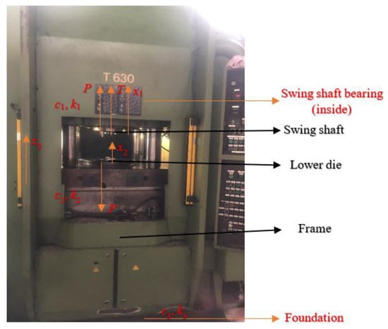
Figure 1.
The structure of a T630 COF machine.
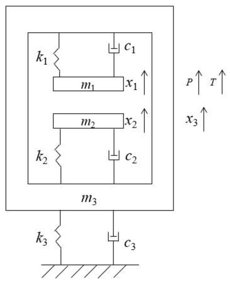
Figure 2.
The dynamics model of a T630 COF machine.
Based on the generalized dissipation Lagrange principle and dynamics model of the T630 COF machine, the dynamics equation of the T630 COF machine is obtained as follows:
where m1 is the mass of the swing shaft (kg), m2 is the total mass of the lower die and lower table (kg), m3 is the mass of the frame (kg), x13 is the relative vertical displacement of the swing shaft with respect to the frame (m), x23 is the relative vertical displacement of the lower die with respect to the frame (m), x32 is the relative vertical displacement of the frame with respect to the lower die (m), x31 is the relative vertical displacement of the frame with respect to the swing shaft (m), P is the COF force (N), T is the vertical external excitation on the swing shaft, k1 is the equivalent stiffness between the swing shaft and swing shaft bearing (N/m), c1 is the equivalent damping between the swing shaft and swing shaft bearing (N·S/m), k2 is the equivalent stiffness between the lower table and frame (N/m), c2 is the equivalent damping between the lower table and frame (N·S/m), k3 is the equivalent stiffness between the frame and foundation (N/m) and c3 is the equivalent damping between the frame and foundation (N·S/m).
According to the kinematics relationship, x13, x23, x32 and x31 can be obtained as follows:
where x1 is the vertical displacement of the swing shaft (m), x2 is the vertical displacement of the lower die (m) and x3 is the vertical displacement of the frame (m).
Introducing Equation (2) into Equation (1), the dynamics equation of the T630 COF machine can be presented as Equation (3):
Based on the former study [12], P can be obtained by parameters of the COF machine, and T can be obtained by the measurement (T = 81,267sin(2π × 4t)). The parameters of the COF machine (and the relevant parameters in Equation (3)) are shown in Table 1.

Table 1.
The parameters of a T630 COF machine.
Based on the parameters of the COF machine, Matlab&Simulink software (MATLAB 2020b) is used to solve the dynamics equation, and the dynamics Simulink model is established in Figure 3.
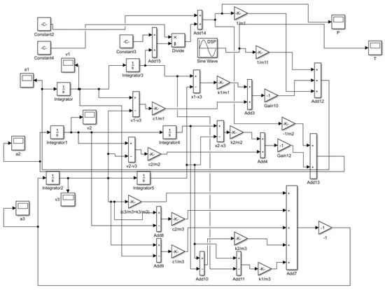
Figure 3.
The dynamics Simulink model of a T630 COF machine.
Based on the oscilloscope results in the dynamics Simulink model, vertical accelerations of the swing shaft, the lower die and the frame are obtained in Figure 4. The amplitudes of these accelerations are 1.97 m/s2, 0.82 m/s2 and 0.12 m/s2, respectively. The swing shaft contacts the product directly, and the vibration on the swing shaft is fierce, which is detrimental to the quality of the product. The vibration controls of the COF machine are proposed in the later section.
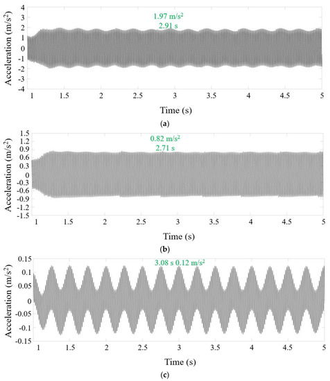
Figure 4.
The vertical accelerations of the swing shaft (a), the lower die (b) and the frame (c).
To verify the effectiveness of oscilloscope results, an acceleration test experiment of the COF machine is conducted, and the experiment instruments are shown in Figure 5.
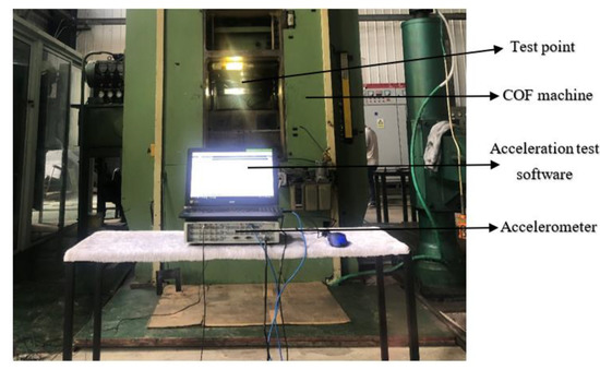
Figure 5.
The acceleration test experiment.
The experimental acceleration of the test point (swing shaft) is presented in Figure 6. The amplitude of the experimental acceleration of the swing shaft is 1.99 m/s2, which is close to the above oscilloscope result (1.97 m/s2). The oscilloscope result is effectively verified.
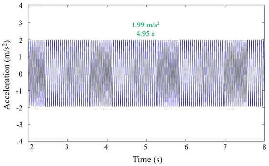
Figure 6.
The experimental acceleration of the test point.
3. Vibration Controls of the COF Machine
LMS, RLS and OCTAVE vibration-control algorithms are three kinds of practical vibration-control algorithms. Applications of these algorithms in the vibration controls of the COF machine are conducted in this section, and Matlab&Simulink software is used to realize these algorithms. Matlab&Simulink software is a multi-domain simulation and model-based design tool for dynamic and embedded systems. This software provides an interactive graphical environment and a library of customizable modules for the design, simulation, execution and testing of various time-varying systems, including communication, control, signal-processing, video-processing and image-processing systems.
3.1. LMS Vibration Control of the COF Machine
The least-mean-squares (LMS) algorithm realizes the update of the weight parameters of the adaptive filter through the criterion of least mean square error. It involves a recursive approach to the Wiener solution of the Wiener filter with the help of the idea of the fastest descent, to avoid the inverse operation of the input signal autocorrelation matrix, and only the prior information of the signal is transmitted, namely, the training sequence. Based on the criterion of least mean square error, the weight coefficients of the filter are updated until convergence to compensate for the linear damage of the signal in the channel. The dynamics Simulink model using LMS vibration control is established in Figure 7. Figure 7 adds the LMS vibration-control algorithm module on the basis of Figure 3.
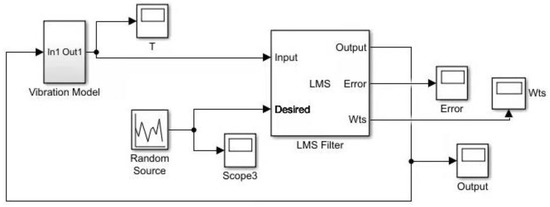
Figure 7.
The dynamics Simulink model using LMS vibration control.
Based on oscilloscope results in the dynamics Simulink model, vertical accelerations of the swing shaft, the lower die and the frame are obtained in Figure 8. The amplitudes of these accelerations tend to be 0 m/s2. The LMS vibration control is significantly beneficial to reducing the vibration of the COF machine.
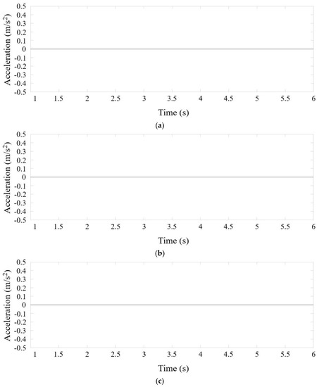
Figure 8.
The vertical accelerations of the swing shaft (a), the lower die (b) and the frame (c).
3.2. RLS Vibration Control of the COF Machine
The recursive least-squares (RLS) algorithm, also known as the least square method, is a fast algorithm of the least square algorithm. The recursive least squares adaptive filter is an optimal filter for a set of known data. It is a purely deterministic minimization problem without making assumptions about the statistical characteristics of the input sequence. Compared with the LMS adaptive transverse filter, it has better performance. The dynamics Simulink model using the RLS vibration control is established in Figure 9. Figure 9 adds the RLS vibration-control algorithm module on the basis of Figure 3.
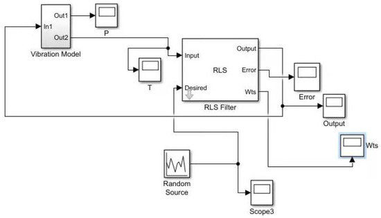
Figure 9.
The dynamics Simulink model using the RLS vibration control.
Based on the oscilloscope results in the dynamics Simulink model, the vertical accelerations of the swing shaft, the lower die and the frame are obtained in Figure 10. Similar to the oscilloscope results in the dynamics Simulink model using the LMS vibration control, the amplitudes of these accelerations also tend to be 0 m/s2. The RLS vibration control is also distinctly conducive to reducing the vibration of the COF machine.
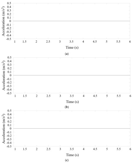
Figure 10.
The vertical accelerations of the swing shaft (a), the lower die (b) and the frame (c).
3.3. OCTAVE Vibration Control of the COF Machine
OCTAVE is another useful vibration-control algorithm, which is good at solving linear and nonlinear numerical problems. The dynamics Simulink model using the OCTAVE vibration control is established in Figure 11. Figure 11 adds the OCTAVE vibration-control algorithm module on the basis of Figure 3.
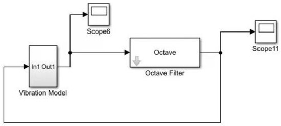
Figure 11.
The dynamics Simulink model using the OCTAVE vibration control.
Based on oscilloscope results in the dynamics Simulink model, the vertical accelerations of the swing shaft, the lower die and the frame are obtained in Figure 12. Though the amplitudes of these accelerations are higher than the other two kinds of vibration-control algorithms, the amplitudes are still obviously lower than the condition without the vibration control. The OCTAVE vibration control is also useful to lower the vibration of the COF machine.
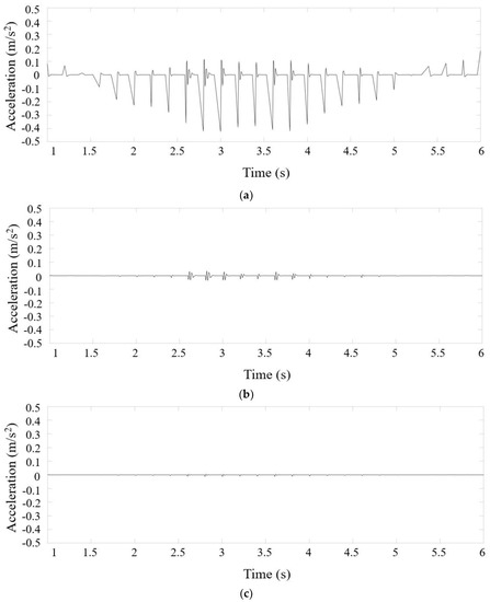
Figure 12.
The vertical accelerations of the swing shaft (a), the lower die (b) and the frame (c).
The realization of the vibration-control algorithms: the operational control of the COF machine system is carried out by the communication between the HMI touch screen and the PLC controller. The PLC controller generates corresponding communication signals according to the parameters set by the touch screen and transmits them to the proportional servo valve, linking the PLC controllers of the computer and the COF machine and importing the vibration-control algorithms into the PLC controller of the computer. After that, the PLC controller of the COF machine is imported into the vibration-control algorithms. Ultimately, the operation of the COF machine is affected by the vibration-control algorithms. The vibration-control algorithms are realized, and the vibration of the COF machine is reduced.
4. Conclusions
In this study, the dynamics model of the COF machine is established, and the vibration performances of some key positions are obtained using Matlab&Simulink software. Subsequently, the vibration performances are effectively verified by conducting a vibration test experiment. Based on the dynamics model of the COF machine and Matlab&Simulink software, LMS, RLS and OCTAVE vibration-control algorithms are applied to reduce the vibration. The conclusions are as follows:
- (1)
- The vibration on the swing shaft severely affects the quality of the forged part because the swing shaft directly contacts the part and the vibration on the swing shaft is fiercer than the other positions.
- (2)
- The vibration amplitudes of the swing shaft applying LMS and RLS vibration controls are close to zero m/s2, and the effects of these two kinds of vibration controls are good.
- (3)
- The effect of the OCTAVE vibration control is worse than the LMS and RLS, but it still obviously reduces the vibration of the COF machine.
Author Contributions
Investigation, methodology and writing—original draft preparation, M.C.; supervision, writing—review and editing, X.N.; resources, writing—review and editing, Z.Z.; data curation, investigation, Y.S.; methodology, validation, Y.T.; data curation, investigation, Y.C.; data curation, investigation, X.S.; and funding acquisition, X.H. All authors have read and agreed to the published version of the manuscript.
Funding
This research was funded by the National Natural Science Foundation of China (No. 51575416), the National Natural Science Foundation of China Youth Fund (No. 52005375) and the China Postdoctoral Science Foundation (2020M672429).
Data Availability Statement
Data sharing is not applicable.
Conflicts of Interest
The authors declare no conflict of interest.
References
- Han, X.H.; Zhang, X.C.; Hua, L. Calculation method for rocking die motion track in cold orbital forging. J. Manuf. Sci. Eng. 2016, 138, 014501. [Google Scholar] [CrossRef]
- Han, X.H.; Zhang, X.C.; Hua, L. Calculation of kinetic locus of upper tool in cold orbital forging machine with two eccentricity rings. J. Mech. Sci. Technol. 2015, 29, 4351–4358. [Google Scholar] [CrossRef]
- Yang, X.; Li, Q.; Tong, C.N.; Liu, Q.H. Vertical vibration model for unsteady lubrication in rolls-strip interface of cold rolling mills. Adv. Mech. Eng. 2012, 2012, 1432–1437. [Google Scholar] [CrossRef]
- Wang, L.; Frayman, Y. A dynamically generated fuzzy neural network and its application to torsional vibration control of tandem cold rolling mill spindles. Eng. Appl. Artif. Intell. 2002, 15, 541–550. [Google Scholar] [CrossRef]
- Liu, Z.Q.; Fu-Cai, L.I.; Chen, K. Vibration data acquisition and alarm judgment system of cold-rolling mills. Noise Vib. Control. 2014, 34, 225–231. [Google Scholar]
- Kim, Y.; Kim, C.W.; Lee, S. Dynamic modeling and numerical analysis of a cold rolling mill. Int. J. Precis. Eng. Manuf. 2013, 14, 407–413. [Google Scholar] [CrossRef]
- Kim, Y.; Kim, C.W.; Lee, S. Experimental and numerical investigation of the vibration characteristics in a cold rolling mill using multibody dynamics. ISIJ Int. 2012, 52, 2042–2047. [Google Scholar] [CrossRef]
- Paul, P.S.; Kumar, C.; Joshua, M. Study on the influence of magnetorheological fluid on tool vibration during end milling process. Int. J. Dyn. Control 2017, 5, 1–8. [Google Scholar] [CrossRef]
- Rashid, A.; Nicolescu, C.M. Design and implementation of tuned viscoelastic dampers for vibration control in milling. Int. J. Mach. Tools Manuf. 2008, 48, 1036–1053. [Google Scholar] [CrossRef]
- Nagaya, K.; Kobayasi, J.; Imai, K. Micro-vibration control of milling machine by using auto tuning absorber for anti-resonance and damping and its cutting tests. Proc. Jpn. Mech. Soc. 1999, 65, 113–120. [Google Scholar] [CrossRef][Green Version]
- Liu, Y.X.; Shu, Y.W.; Hu, W.T. Active vibration control of mechanical servo high speed fine-blanking press. Stroj. Vestn.-J. Mech. Eng. 2021, 67, 445–457. [Google Scholar] [CrossRef]
- Richiedei, D.; Tamellin, I.; Trevisani, A. Unit-rank output feedback control for antiresonance assignment in lightweight systems. Mech. Syst. Signal Processing 2022, 164, 108250. [Google Scholar] [CrossRef]
- Richiedei, D.; Tamellin, I.; Trevisani, A. Pole-zero assignment by the receptance method: Multi-input active vibration control. Mech. Syst. Signal Processing 2022, 172, 108976. [Google Scholar] [CrossRef]
- Francisco, B.C.; Gerardo, S.N. Output feedback dynamic control for trajectory tracking and vibration suppression. Appl. Math. Model. 2020, 79, 793–808. [Google Scholar]
- Francisco, B.C.; Gerardo, S.N. Generalized nonlinear stiffness identification on controlled mechanical vibrating systems. Asian J. Control 2019, 21, 1281–1292. [Google Scholar]
- Zhou, K.; Zhang, J.W.; Li, Q.S. Control performance of active tuned mass damper for mitigating wind-induced vibrations of a 600-m-tall skyscraper. J. Build. Eng. 2021, 45, 103646. [Google Scholar] [CrossRef]
- Hua, L.; Chen, M.Z.; Han, X.H. Research on vibration model and vibration performance of cold orbital forging machines. Proc. Inst. Mech. Eng. Part B J. Eng. Manuf. 2021, 236, 828–843. [Google Scholar] [CrossRef]
- Gu, Z.Q.; Chen, M.Z.; Wang, C.Y. Static and dynamic analysis of a 6300 KN cold orbital forging machine. Processes 2021, 9, 7. [Google Scholar] [CrossRef]


Publisher’s Note: MDPI stays neutral with regard to jurisdictional claims in published maps and institutional affiliations. |
© 2022 by the authors. Licensee MDPI, Basel, Switzerland. This article is an open access article distributed under the terms and conditions of the Creative Commons Attribution (CC BY) license (https://creativecommons.org/licenses/by/4.0/).