Abstract
Excessive temperature is detrimental to the operation stability of the automobile drive axle. It is necessary to judge whether the highest temperature exceeds the limited dangerous temperature and study the effects of key factors on reducing the temperature. In this study, the temperature field distribution (TFD) of the automobile drive axle is revealed using the thermal network method (TNM). Compared with the experimentation and finite element analysis (FEA), the TNM is more convenient for obtaining the temperature. Subsequently, the highest temperature of the automobile drive axle is clear and applied to judge whether the highest temperature exceeds the limited dangerous temperature. On the basis of the TNM, the structure and parameter effects of the automobile drive axle on reducing the temperature are studied, which improves the operation stability and working life. Several conclusions can be drawn. The highest temperatures of two-axle and planetary automobile drive axles are both located in the motor. Compared with the two-axle drive axle, the highest temperature of the planetary drive axle is obviously lower. Therefore, in terms of the planetary drive axle, the possibility of exceeding the limited dangerous temperature is lower. In addition, on the premise of ensuring the normal operation, the motor output power, the friction coefficient among teeth, the helical angle of the gear, and the thermal transfer coefficient of the lubricating oil can be optimized to be lower for reducing the temperature of the automobile drive axle.
1. Introduction
The automobile drive axle is the pivotal component of the automobile power system and, therefore, requires a strictly controlled temperature. If the temperatures of some parts in the automobile drive axle exceed the limited dangerous temperature, the operation stability and working life of the drive axle will be influenced. Therefore, it is necessary to obtain the TFD of the automobile drive axle, and the highest temperature can be applied for judging whether the temperature exceeds the limited dangerous temperature. Furthermore, there are many high temperature parts in the automobile drive axle owing to the continuous heat production from the thermal source. It is necessary to study the effects of key factors on reducing the temperature, which is beneficial to improving the operation stability and working life.
The reducer, the motor, and differential are three key components in the automobile drive axle. Recently, some researchers conducted a thermal analysis study of the parts in these components using experimentation [1]. Ref. [2] put forward a novel idea to obtain the TFD of the high-speed motor shaft. Ref. [3] conducted an experiment study on the thermal characteristics of a motor using longitudinal transducers. Ref. [4] carried out some thermal imaging experiments of a vehicle motor for temperature performances within low visibility at night. Ref. [5] proposed an experimental method for the TFD of the bearing. Ref. [6] studied the development of the temperature in a bearing using the experiment and analysis. Ref. [7] studied the TFD of the motor, and the results were verified by an experiment. Ref. [8] revealed a way combining the experiment and analysis to research the effects of different parameters on the temperature of the gearbox. Ref. [9] conducted some experiments for the thermal characterization of a low-backlash planetary gearbox.
Some other scholars adopted the FEA for the thermal analysis of parts in the automobile drive axle. Ref. [10] analyzed the thermal performances of an integrated motor using the FEA software. Ref. [11] applied three-dimension FEA to obtain the rotational core loss of a high-speed motor. Ref. [12] proposed an efficient thermal computation model of a permanent magnet synchronous motor using FEA. Ref. [13] obtained the TFD of the gearbox using the FEA simulation method. Ref. [14] described the two-dimensional FEA to obtain the TFD of gears. Ref. [15] conducted FEA-based simulations of the gearbox to investigate the methods for reducing the temperature. Ref. [16] performed an FEA-based steady state thermal analysis of a gearbox system and demonstrated that the thermal property of the oil directly influenced the condition of the gearbox.
The TNM is another method which is used for the thermal analysis of the mechanical components. Compared with experimentation and FEA, the TNM costs less computational time and needs less investment in the experimental equipment for obtaining the TFD of the mechanical component. Ref. [17] conducted a thermal analysis of a reducer for the electric vehicle using the TNM and studied the influences of the lubricant supply on the temperature of the reducer. Ref. [18] used the TNM to predict the whole temperature of a two-speed automatic transmission. Ref. [19] calculated component temperatures in gearboxes within transient operation conditions by the TNM. Ref. [20] established a thermal network model, which made it possible to predict the thermal loss in a six-speed manual gearbox. Ref. [21] set up a hybrid thermal model which was applied to calculate the temperature distribution in a permanent magnet motor. Ref. [22] also applied the TNM to analyze the TFD of permanent magnet machines. Ref. [23] developed a novel TNM for the transient thermal analysis of the spindle-bearing system. Ref. [24] presented an inverse TNM to study the real-time thermal–mechanical–frictional coupling performances of bearings. As illustrated in the above literature, the existing studies are mainly on using the TNM to separately conduct the thermal analysis of some components in the automobile drive axle but not the whole automobile drive axle. However, in actual conditions, temperatures of these components in the automobile drive axle affect each other, and temperatures are, therefore, not precise. So, it is necessary to regard the automobile drive axle as an entirety and consider the thermal flow among components. After that, the TFD of the whole automobile drive axle can be obtained, and the temperatures of the components are more precise.
In this study, the automobile drive axle is regarded as an entirety, and the TFD of the whole automobile drive axle is revealed using the TNM. Subsequently, the highest temperature of the automobile drive axle is clear and applied to judge whether the highest temperature exceeds the limited dangerous temperature. Based on the TNM, the structure and parameter effects of the automobile drive axle on reducing the temperature are studied, which improves the operation stability and working life.
2. Thermal Analysis of a Two-Axle Automobile Drive Axle
2.1. Thermal Network Model of a Two-Axle Automobile Drive Axle
2.1.1. Thermal Network Diagram of a Two-Axle Automobile Drive Axle
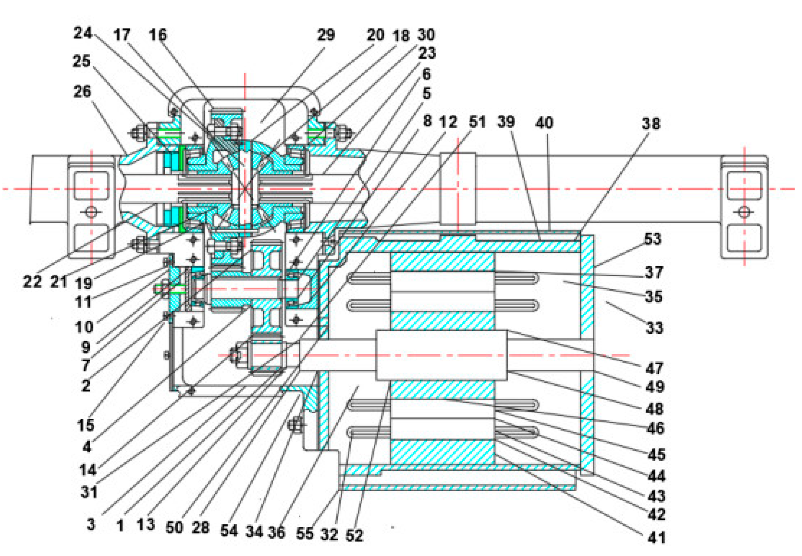
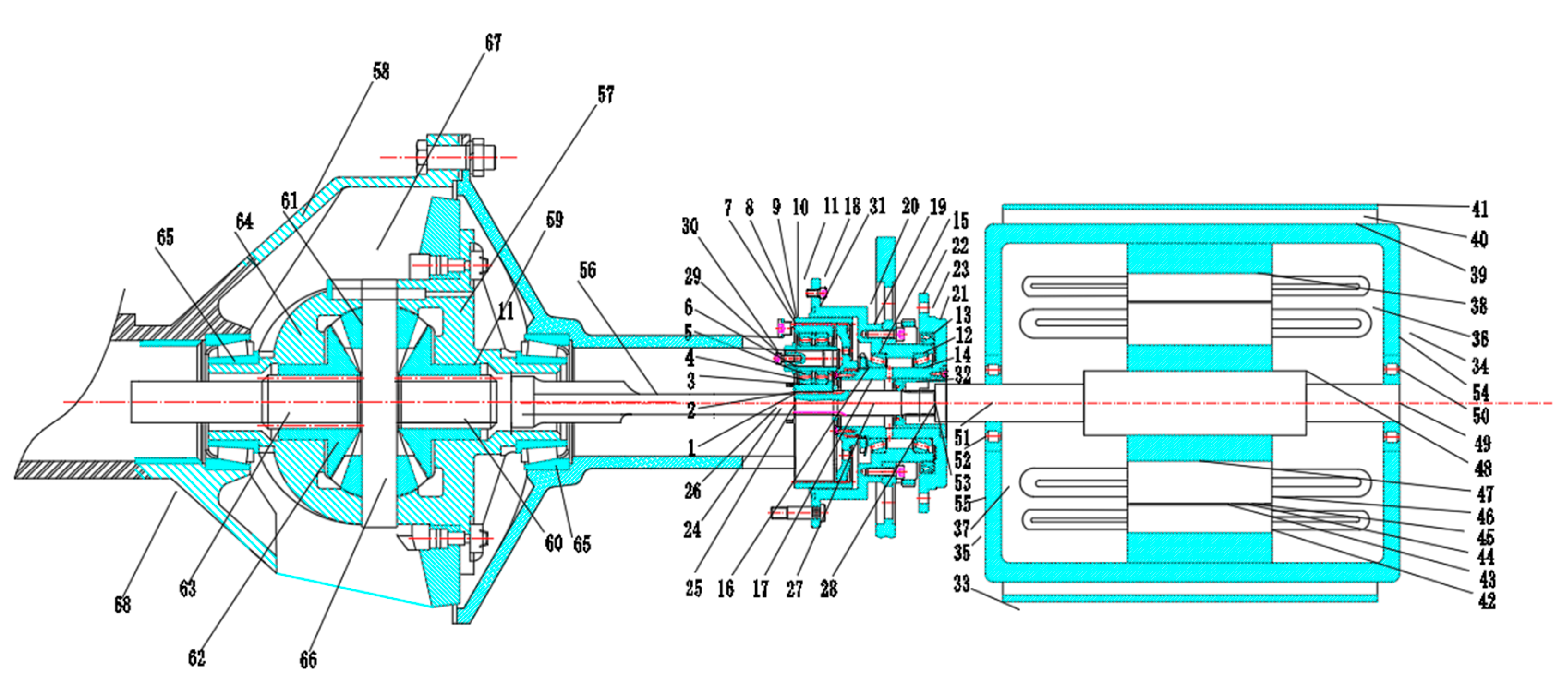
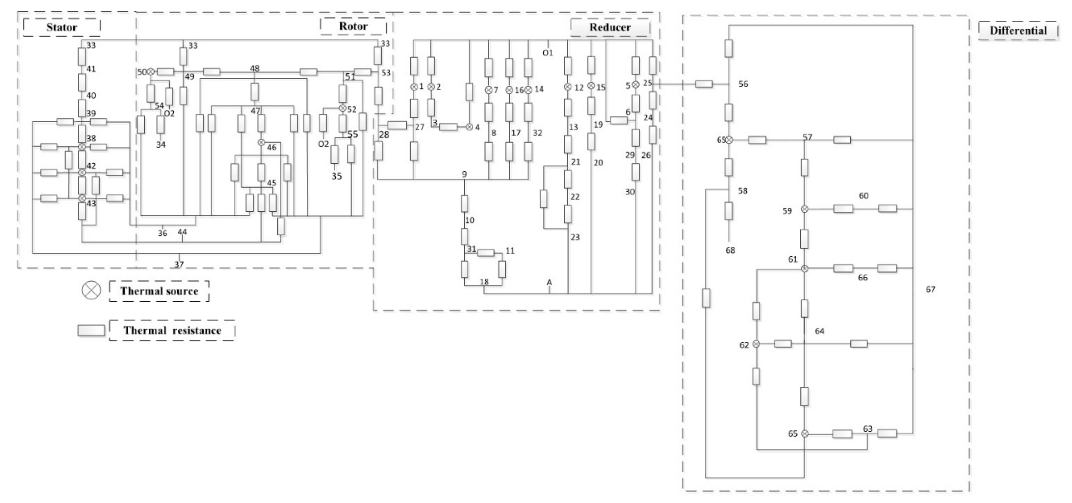
Based on the structure of a two-axle automobile drive axle, shown in Figure 1, the key parts of the drive axle are set as fifty-five nodes. In the thermal network, the thermal resistances among the fifty-five nodes are regarded as the resistances among these nodes. The thermal flow among the fifty-five nodes is regarded as the current among these nodes. The temperature differences among the fifty-five nodes are regarded as the voltage differences among these nodes. Subsequently, the thermal network of the two-axle automobile drive axle is regarded as the electric network. In addition, there are some hypotheses on the thermal network model: the thermal radiation effect is not considered in the thermal network model; any parts in the two-axle automobile drive axle are regarded as the same material property, and the thermal conductivity will not be different owing to the different material property; and the two-axle automobile drive axle is regarded as the steady state, and the material properties of any parts in the two-axle automobile drive axle are regarded as constant. Ultimately, the thermal network diagram of the drive axle is expressed in the form of the electric network diagram, illustrated in Figure 2.

Figure 1.
The structure of the two-axle automobile drive axle.
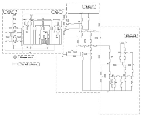
Figure 2.
The thermal network diagram of the two-axle automobile drive axle.

Table 1.
Fifty-five nodes in the thermal network diagram.
2.1.2. Thermal Balance Equations of a Two-Axle Automobile Drive Axle
Based on the Kirchhoff theory, the thermal flow rule, and heat conservation principle, the thermal balance equation of the two-axle automobile drive axle is obtained:
where Rim is the thermal resistance between node i and node m (°C/W), Rni is the thermal resistance between node n and node i (°C/W), mi is the quality of node i (kg), ci is the specific heat of node i (J/(kg·K)), ∆τ is the time (s), Ti is the temperature of node i (°C), Tm is the temperature of node m (°C), Tn is the temperature of node n (°C), and Qi is the thermal production generated by node i (if node i is not the thermal source, Qi will be zero) (W). Based on the hypothesis in Section 2.1.1, the two-axle automobile drive axle is regarded as the steady state. The temperature stays constant, and ∆Ti/∆τ is zero.
2.2. Thermal Analysis Results of a Two-Axle Automobile Drive Axle
Parameters of the motor, the reducer, and differential are presented in Table 2, Table 3 and Table 4.
Table 2.
Parameters of the motor.
Table 3.
Parameters of the reducer.
Table 4.
Parameters of the differential.
Based on our former study [1] and parameters of the two-axle automobile drive axle, the thermal sources and thermal resistances in the two-axle automobile drive axle are obtained. Subsequently, bringing the thermal sources and thermal resistances into forty-five thermal balance equations similar to Equation (1) and solving these equations, the temperatures of forty-five nodes are obtained. Based on the temperatures of forty-five nodes, the TFD of the two-axle automobile drive axle is drawn in Figure 3.
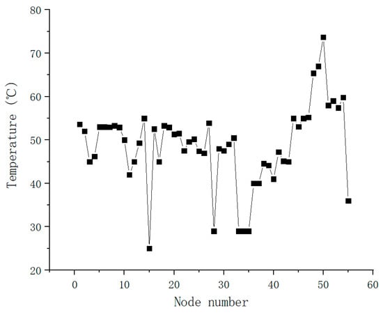
Figure 3.
The TFD of the two-axle automobile drive axle (p = 22 kW).
Based on the TFD of the two-axle automobile drive axle, it can be found that:
- (1)
- The highest temperatures in the reducer, the motor, and differential are the temperatures of nodes 1, 50, and 14. Notably, the temperature (73.7 °C) of the spindle contacting front-end cover (node 50) is the highest temperature of the two-axle automobile drive axle. The reason is that this part is the uppermost thermal source of the two-axle automobile drive axle, and thermal dissipation is more difficult than in other parts.
- (2)
- The average temperature of the motor is higher than the differential and reducer. The average temperature of the reducer is fiercer than the differential.
- (3)
- The temperature of nodes 1, 5, 14, 18, 19, 38, 42, 43, 46, 50, and 52 are high. These nodes are distributed near the thermal sources of the two-axle automobile drive axle, so these temperatures are higher than others.
- (4)
- The temperature differences among some adjacent nodes are not distinct. However, the temperature differences among different nodes on the shell are apparent.
2.3. Validation of Thermal Network Method
In our last study [1], we obtained the TFD of the triple-phase asynchronous motor-reducer coupling system using the TNM. The validation of the TNM was conducted using the temperature test.
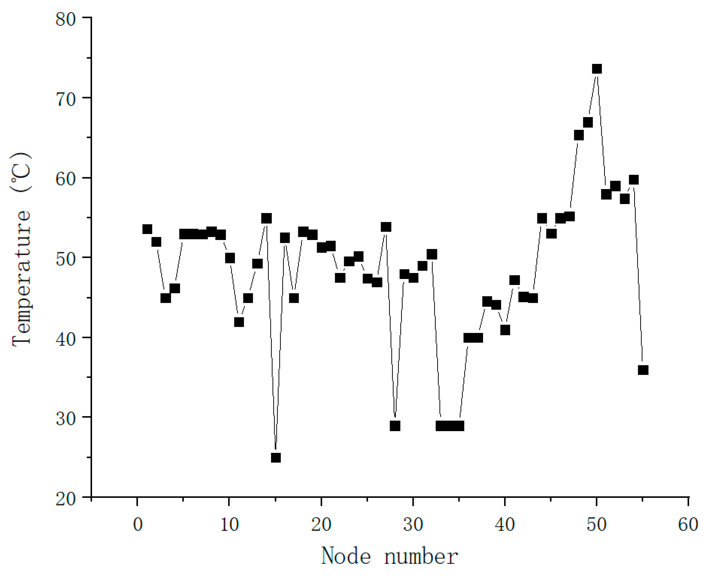
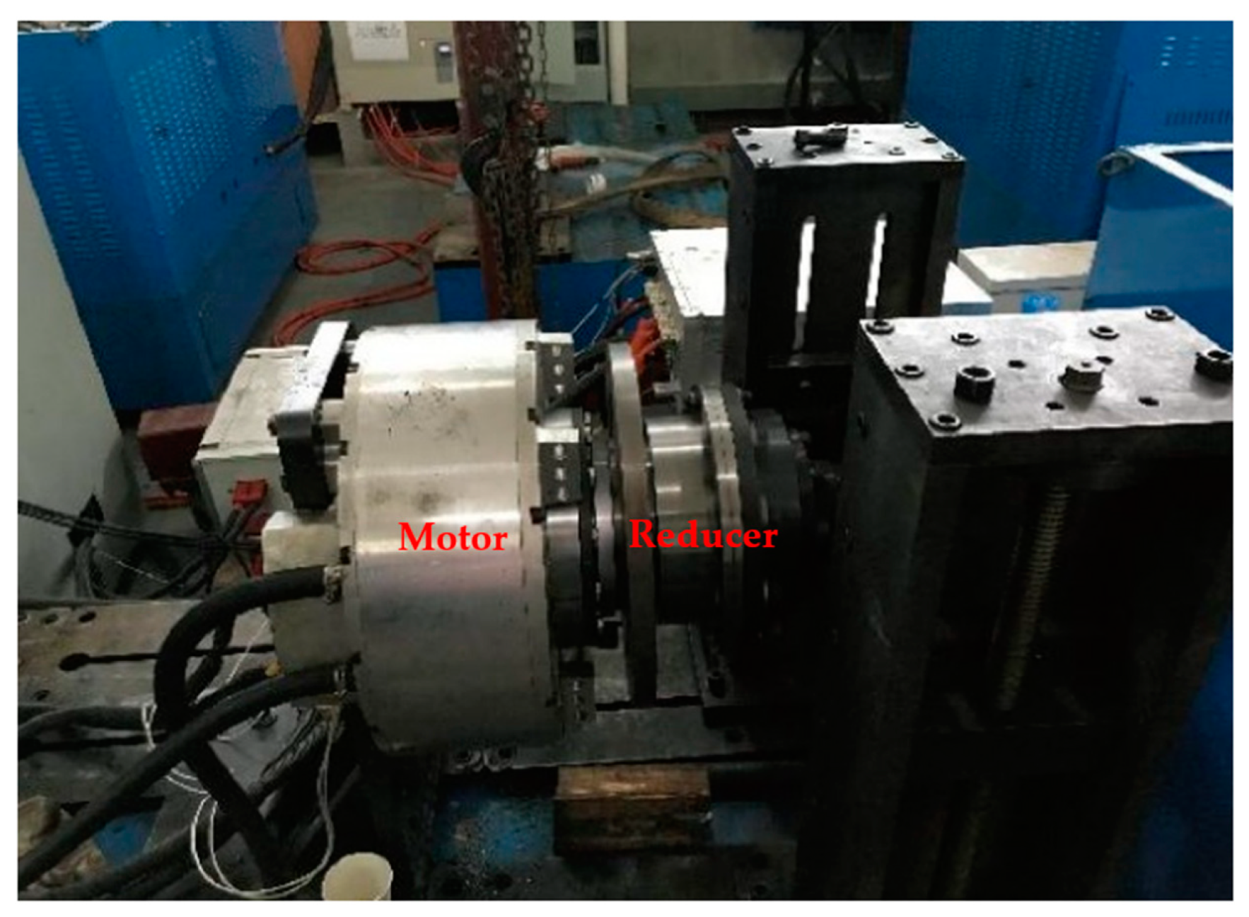
The temperature test is illustrated in Figure 4.
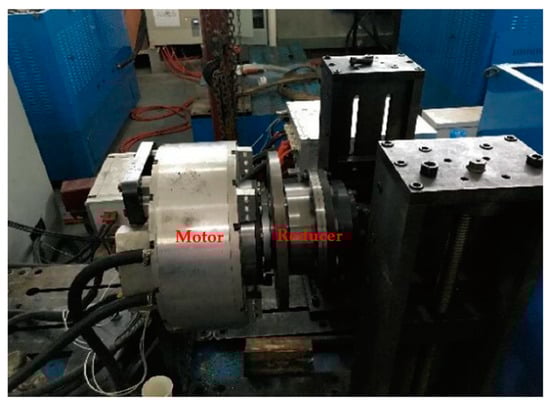
Figure 4.
The temperature test experiment.
The temperature test result was obtained by a thermal imager, illustrated in Figure 5.
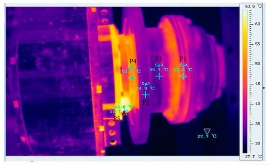
Figure 5.
The temperature test result.
Comparison of the temperatures of some points in the TNM with the experimentation is presented in Table 5.
Table 5.
Temperatures of some points in the TNM and experimentation.
Obviously, differences among results of the TNM and experimentation were within the error range. The effectiveness of the TNM is verified, and the TNM can be further used to study the effects of key factors on reducing the temperature, set out in the next section.
3. Effects of Key Factors on Reducing the Temperature
3.1. Structural Effect of an Automobile Drive Axle
The structure of the automobile drive axle is redesigned from the two-axle drive axle to the planetary drive axle for reducing the temperature, and the structure of the planetary automobile drive axle is shown in Figure 6. Similar to the two-axle automobile drive axle, the thermal network diagram of the planetary automobile drive axle is expressed in the form of the electric network diagram, shown in Figure 7. The key parts of the drive axle are set as sixty-eight nodes.
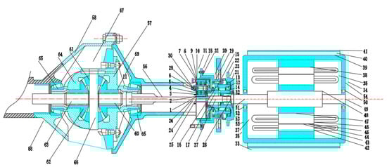
Figure 6.
The structure of the planetary automobile drive axle.
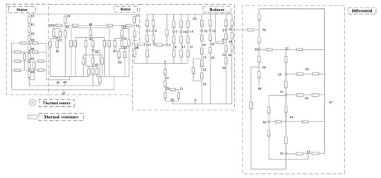
Figure 7.
The thermal network diagram of the planetary automobile drive axle.
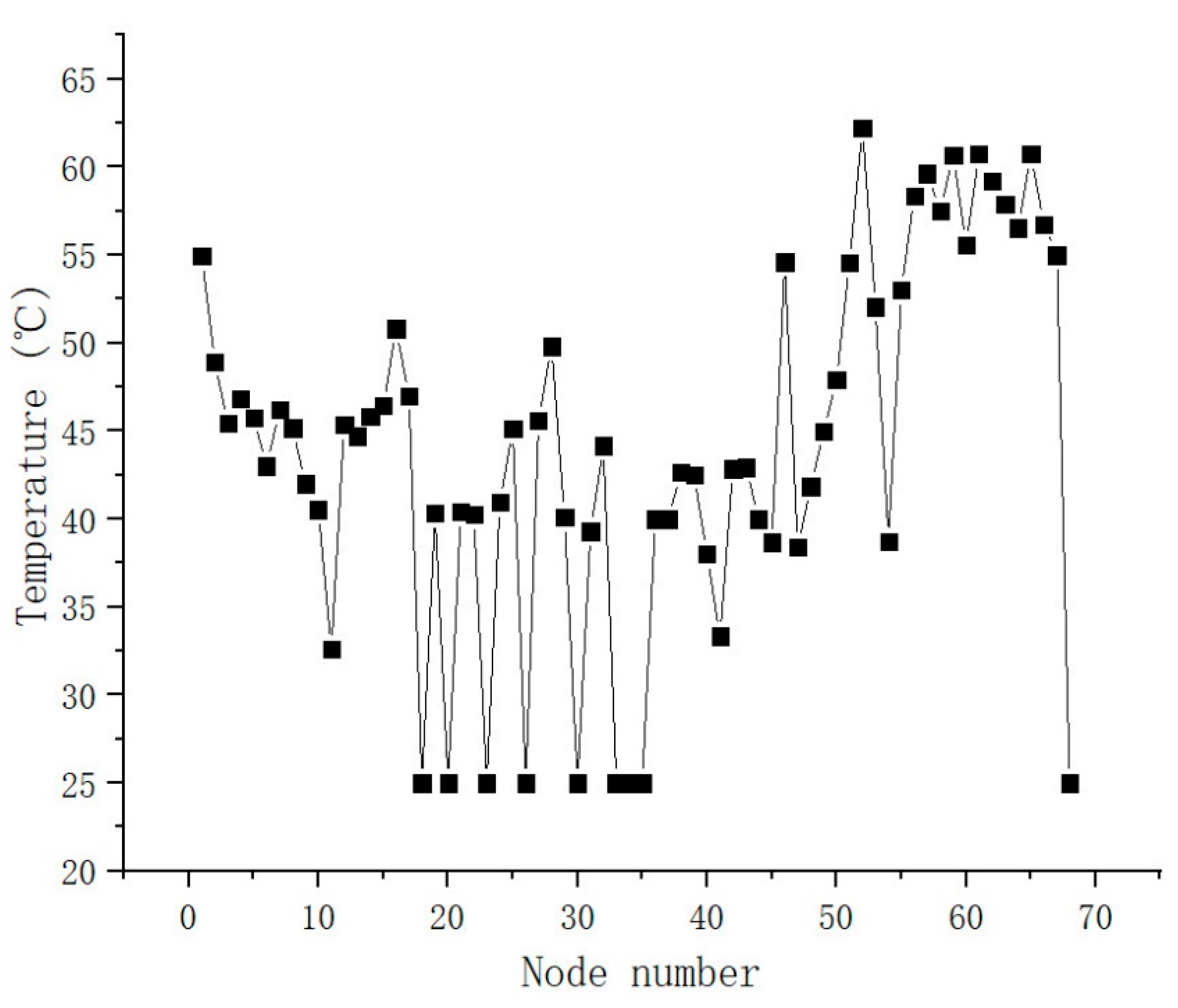
Temperatures of the sixty-eight nodes in the planetary automobile drive axle are obtained using the TNM, and the TFD is drawn in Figure 8.
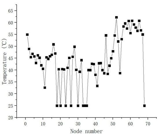
Figure 8.
The TFD of the planetary automobile drive axle (p = 22 kW).
The highest temperature (62.2 °C) of the planetary automobile drive axle is also located in the motor (node 52). Compared with the two-axle drive axle, the highest temperature of the planetary drive axle is obviously lower. Therefore, as for the planetary drive axle, the possibility of exceeding the limited dangerous temperature is lower. The redesigned structure of the automobile drive axle is effective and beneficial to improving the working life.
3.2. Parameter Effects of an Automobile Drive Axle
Based on the calculation formulas of the thermal sources and thermal resistances in our former study [1], the motor output power, the friction coefficient among teeth, and helical angle of the gear have an influence on the thermal sources. Similarly, the lubricating oil parameter affects the thermal resistances. These parameters have an impact on the temperature field of the automobile drive axle. The effects of these parameters on reducing the temperature are researched in this section.
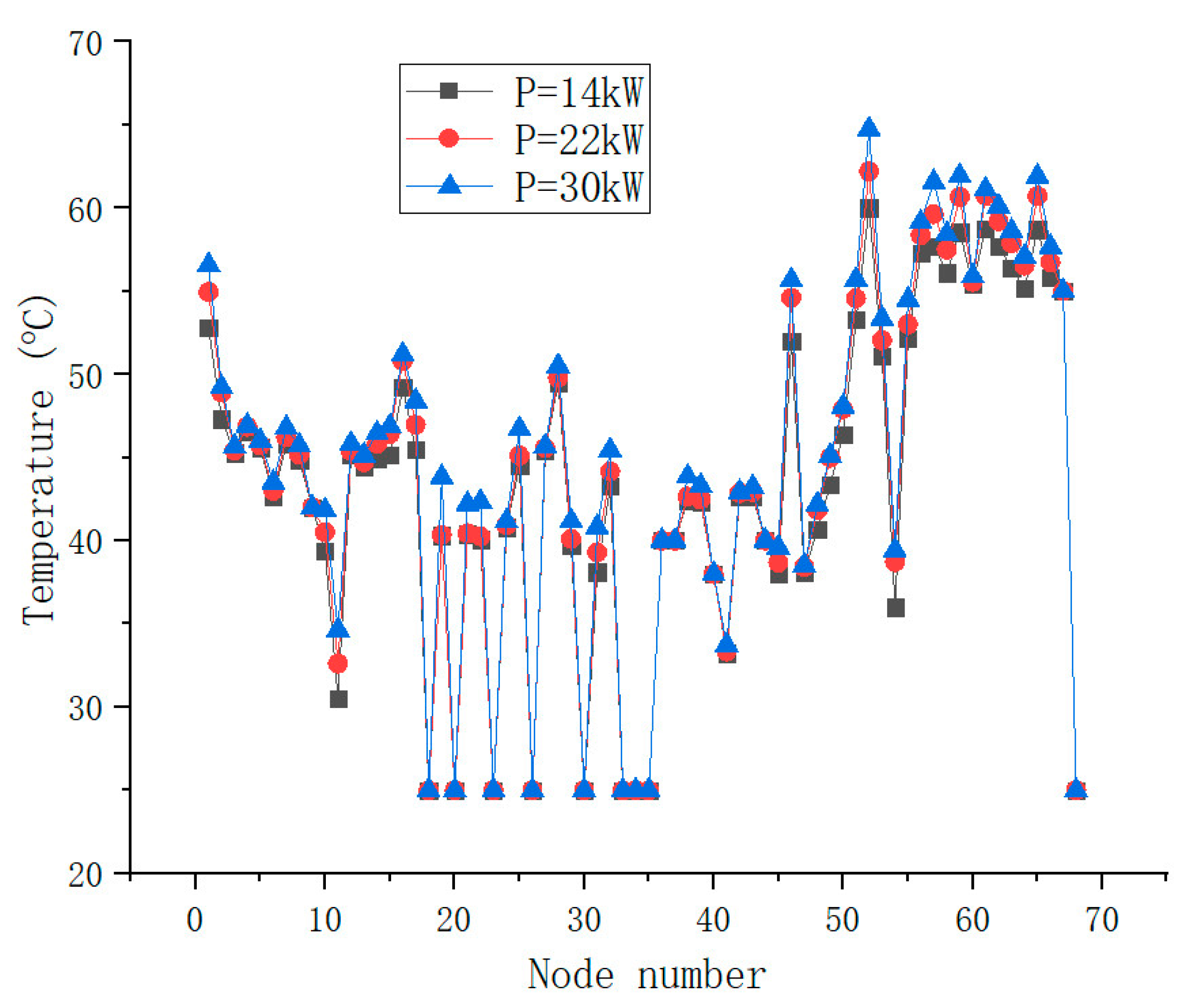
3.2.1. Effect of Motor Output Power
As shown in Figure 9, the TFD of the planetary automobile drive axle with the different motor output powers is obtained using the TNM. The corresponding highest temperatures with the motor power of 14 kW, 22 kW, and 30 kW are 60 °C, 62.2 °C, and 64.74 °C. The temperature of the planetary automobile drive axle rises as the motor output power increases. Particularly, the temperature of the parts in the motor increases most obviously, and the temperature of the parts in the differential increases relatively slightly. On the premise of ensuring normal operation, the motor output power can be optimized to be lower for reducing the temperature of the automobile drive axle.
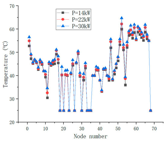
Figure 9.
The TFD with the different motor output powers.
3.2.2. Effect of Friction Coefficient among Teeth
As shown in Figure 10, the TFD of the planetary automobile drive axle with the different friction coefficients among teeth is obtained using the TNM. The corresponding highest temperatures with the friction coefficient of 0.02, 0.04, and 0.06 are 59.74 °C, 60.86 °C, and 62.2 °C. The temperature of the planetary automobile drive axle rises as the friction coefficient increases. Particularly, the temperature of the gear (the thermal source) in the reducer and differential increases most obviously, and the temperature of the parts in the motor increases relatively slightly. The reason is that the friction coefficient mainly affects the thermal production of the gear. The temperature of the gear therefore increases significantly with increasing the friction coefficient. On the premise of ensuring normal operation, the friction coefficient can be optimized to be smaller for reducing the temperature of the automobile drive axle by:
- (1)
- During the process of gears, applying more fashioning or developing the process technology to improve the machining precision.
- (2)
- Further polishing gears after manufacturing.
- (3)
- Replacing gears regularly with new ones
- (4)
- Adopting the lubricating material with good lubrication properties to act as an intermediate medium between gears, and replenishing the lubricating material regularly.
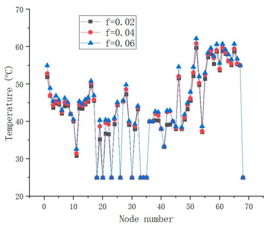
Figure 10.
The TFD with the different friction coefficients among teeth.
Figure 10.
The TFD with the different friction coefficients among teeth.

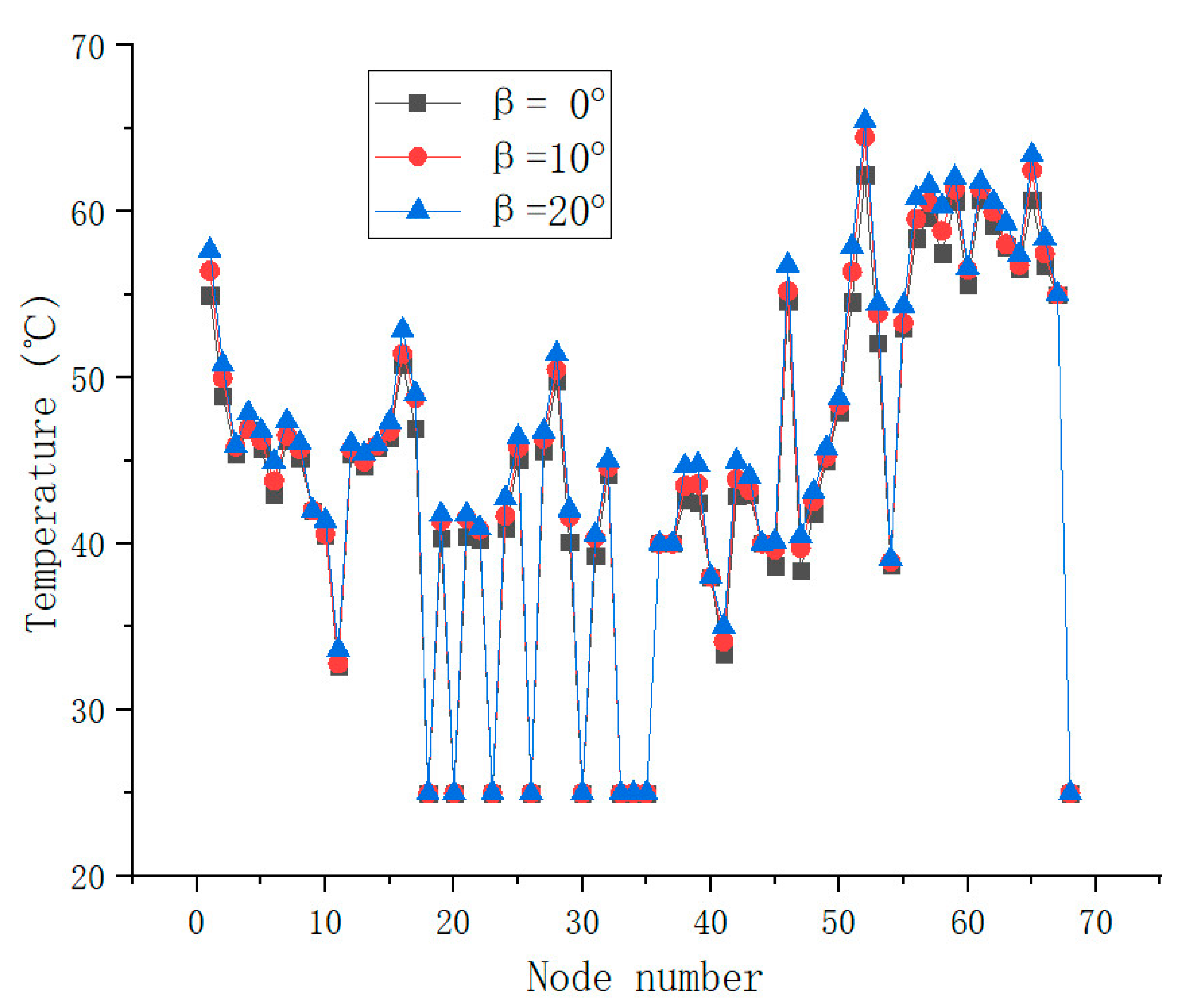
3.2.3. Effect of Helical Angle of Gears
As shown in Figure 11, the TFD of the planetary automobile drive axle with the different helical angles of the gear is obtained using the TNM. The corresponding highest temperatures with the helical angle of 0°, 10°, and 20° are 62.2 °C, 64.47 °C, and 65.43 °C. The temperature of the planetary automobile drive axle rises as the helical angle increases. In particular, the temperature of the gear (the thermal source) in the reducer increases most obviously, and the temperature of the parts in the differential and motor increases relatively slightly. The reason is that the helical angle mainly affects the heat production of the gear in the reducer. The temperature of the gear in the reducer, therefore, increases significantly with increasing the helical angle. On the premise of ensuring normal operation, the helical angle can be optimized to be smaller for reducing the temperature of the automobile drive axle.
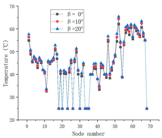
Figure 11.
The TFD with the different helical angles of the gear.
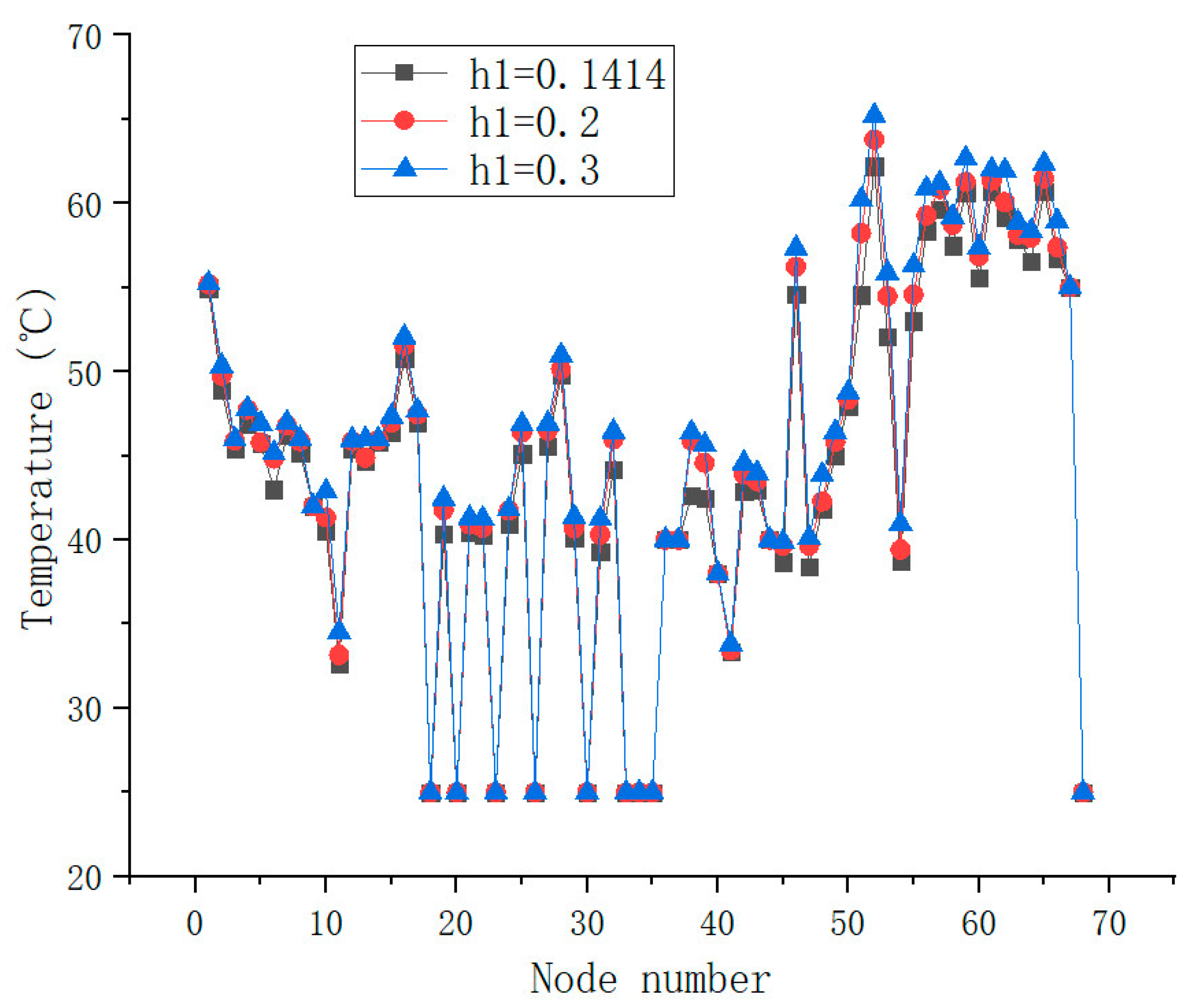
3.2.4. Effect of Lubricating Oil Parameter
As shown in Figure 12, the TFD of the planetary automobile drive axle with the different thermal transfer coefficients of the lubricating oil is obtained by the TNM. The corresponding highest temperatures with the thermal transfer coefficient of 0.1414, 0.2, and 0.3 are 62.2 °C, 63.79 °C, and 65.21 °C. The temperature of the planetary automobile drive axle rises as the thermal transfer coefficient increases. On the premise of ensuring normal operation, the thermal transfer coefficient can be optimized to be smaller for reducing the temperature of the automobile drive axle.
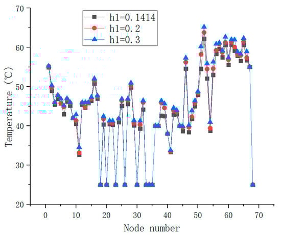
Figure 12.
The TFD with the different thermal transfer coefficients of the lubricating oil.
4. Conclusions
In this study, the temperature field distribution (TFD) of the automobile drive axle is revealed using the thermal network method (TNM). Based on the TNM, the structure and parameter effects of the automobile drive axle on reducing the temperature are studied, which improves the operation stability and working life. Several conclusions can be drawn:
- (1)
- The highest temperature (73.7 °C) of the two-axle automobile drive axle is located in the motor. In addition, the average temperature of the motor is higher than the differential and reducer, and the average temperature of the reducer is higher than the differential.
- (2)
- The highest temperature (62.2 °C) of the planetary automobile drive axle is also located in the motor. Compared with the two-axle drive axle, the highest temperature of the planetary drive axle is obviously lower. Therefore, as for the planetary drive axle, the possibility of exceeding the limited dangerous temperature is lower.
- (3)
- The corresponding highest temperatures of the planetary automobile drive axle with the motor power of 14 kW, 22 kW, and 30 kW are 60 °C, 62.2 °C, and 64.74 °C. The corresponding highest temperatures with the friction coefficient of 0.02, 0.04, and 0.06 are 59.74 °C, 60.86 °C, and 62.2 °C. The corresponding highest temperatures with the helical angle of 0°, 10°, and 20° are 62.2 °C, 64.47 °C, and 65.43 °C. The corresponding highest temperatures with the thermal transfer coefficient of 0.1414, 0.2, and 0.3 are 62.2 °C, 63.79 °C, and 65.21 °C. On the premise of ensuring normal operation, the motor output power, the friction coefficient among teeth, the helical angle of the gear, and thermal transfer coefficient of the lubricating oil can be optimized to be lower for reducing the temperature of the automobile drive axle.
Author Contributions
X.N.: investigation, methodology, writing—original draft preparation; M.C.: supervision, writing—review and editing; Z.Z.: resources, writing—review and editing; Y.S.: data curation, investigation; W.X.: methodology, validation; Y.C.: data curation, investigation; X.S.: data curation, investigation; Z.W.: methodology, validation. All authors have read and agreed to the published version of the manuscript.
Funding
This research was funded by the National Natural Science Foundation of China (No. 51575416), 111 Project (B17034), Innovative Research Team Development Program of Ministry of Education of China (No. IRT_17R83).
Institutional Review Board Statement
Not applicable.
Informed Consent Statement
Not applicable.
Data Availability Statement
Data sharing not applicable.
Conflicts of Interest
The authors declare no conflict of interest.
References
- Chen, M.Z.; Zhuang, W.H.; Deng, S.; Zhu, C. Thermal analysis of the triple-phase asynchronous motor-reducer coupling system by thermal network method. Proc. Inst. Mech. Eng. Part D J. Automob. Eng. 2020, 234, 2851–2861. [Google Scholar] [CrossRef]
- Hasegawa, T.; Kawashima, N. A new technique to measure the temperature of a rotating motor shaft. Appl. Therm. Eng. 2009, 29, 317–323. [Google Scholar] [CrossRef]
- Li, H.; Chen, W.S.; Tian, X.Q.; Liu, J. An experiment study on temperature characteristics of a linear ultrasonic motor using longitudinal transducers. Ultrasonics 2019, 95, 6–12. [Google Scholar] [CrossRef] [PubMed]
- Wang, X. Thermal imaging experiments of motor vehicles under low visibility at night. In Proceedings of the International Symposium on Photoelectronic Detection and Imaging, Beijing, China, 8 September 2011. [Google Scholar]
- Zhou, X.; Zhang, H.; Hao, X.; Liao, X.; Han, Q. Investigation on thermal behavior and temperature distribution of bearing inner and outer rings. Tribol. Int. 2019, 130, 289–298. [Google Scholar] [CrossRef]
- Takabi, J.; Khonsari, M. Experimental testing and thermal analysis of ball bearings. Tribol. Int. 2013, 60, 93–103. [Google Scholar] [CrossRef]
- Chai, F.; Tang, Y.; Pei, Y.; Liang, P.; Gao, H. Temperature field accurate modeling and cooling performance evaluation of direct-drive outer-rotor air-cooling in-wheel motor. Energies 2016, 9, 818. [Google Scholar] [CrossRef] [Green Version]
- Long, H.; Lord, A.; Gethin, D.; Roylance, B.J. Operating temperatures of oil-lubricated medium-speed gears: Numerical models and experimental results. Proc. Inst. Mech. Eng. Part G J. Aerosp. Eng. 2003, 217, 87–106. [Google Scholar] [CrossRef] [Green Version]
- Concli, F. Thermal and efficiency characterization of a low-backlash planetary gearbox: An integrated numerical-analytical prediction model and its experimental validation. Proc. Inst. Mech. Eng. Part J J. Eng. Tribol. 2016, 230, 8. [Google Scholar] [CrossRef]
- Abebe, R.; Vakil, G.; Calzo, G.L.; Cox, T.; Gerada, C.; Johnson, M. FEA based thermal analysis of various topologies for Integrated Motor Drives (IMD). In Proceedings of the Conference of the IEEE Industrial Electronics Society, Yokohama, Japan, 9–12 November 2015. [Google Scholar]
- Huang, Y.K.; Zhu, J.G.; Guo, Y.G. Thermal analysis of high-speed SMC motor based on thermal network and 3-D FEA with rotational core loss included. IEEE Trans. Magn. 2009, 45, 4680–4683. [Google Scholar] [CrossRef]
- Liu, C.S.; Zou, J.B.; Xu, Y.X.; Yu, G. An efficient thermal computation model of PMSM based on FEA results and interpolation. IEEE Trans. Appl. Supercond. 2021, 31, 1–4. [Google Scholar] [CrossRef]
- Fernandes, C.; Rocha, D.; Martins, R.; Magalhães, L.; Seabra, J.H. Finite element method model to predict bulk and flash temperatures on polymer gears. Tribol. Int. 2018, 120, 255–268. [Google Scholar] [CrossRef]
- Roda, V.; Sanchez, F. A 2D finite element based approach to predict the temperature field in polymer spur gear transmissions. Mech. Mach. Theory 2019, 133, 210. [Google Scholar]
- Patil, P.; Kumar, A. Dynamic structural and thermal characteristics analysis of oil-lubricated multi-speed transmission gearbox: Variation of load, rotational speed and convection heat transfer. Iran. J. Sci. Technol. Trans. Mech. Eng. 2016, 41, 281–291. [Google Scholar] [CrossRef]
- Shukla, A.; Kumar, A. Design and thermal characteristic analysis of gearbox system based on finite element analysis (FEA). In Proceedings of the 14th Asia-Pacific Physics Conference, Hyderabad, India, 24–25 July 2020. [Google Scholar]
- Zhu, B.; Wang, X.; Luo, L.; Zhang, N.; Liu, X. Influence of lubricant supply on thermal and efficient performances of a gear reducer for electric vehicles. J. Tribol.-Trans. ASME 2022, 144, 1–22. [Google Scholar] [CrossRef]
- Liu, Y.G.; Peng, J.Y.; Wang, B.; Qin, D.; Ye, M. Bulk temperature prediction of a two-speed automatic transmission for electric vehicles using thermal network method and experimental validation. Proc. Inst. Mech. Eng. Part D J. Automob. Eng. 2018, 233, 2585–2598. [Google Scholar] [CrossRef]
- Paschold, C.; Sedlmair, M.; Lohner, T.; Stahl, K. Calculating component temperatures in gearboxes for transient operation conditions. Forsch. Ing.-Eng. Res. 2021, 85, 1–14. [Google Scholar] [CrossRef]
- Changenet, C.; Oviedo, X.; Velex, P. Power loss predictions in geared transmissions using thermal networks-application to a six speed manual gearbox. Trans. ASME J. Mech. Des. 2005, 128, 618–625. [Google Scholar] [CrossRef]
- Guo, Y.; Zhu, J.; Wu, W. Thermal analysis of soft magnetic composite motors using a hybrid model with distributed heat sources. IEEE Trans. Magn. 2005, 41, 2124–2128. [Google Scholar]
- Qi, J.; Hua, W.; Zhang, H. Thermal analysis of modular-spoke-type permanent-magnet machines based on thermal network and FEA method. IEEE Trans. Magn. 2019, 55, 1–5. [Google Scholar] [CrossRef]
- Yan, K.; Hong, J.; Zhang, J.; Mi, W.; Wu, W. Thermal-deformation coupling in thermal network for transient analysis of spindle-bearing system. Int. J. Therm. Sci. 2016, 104, 1–12. [Google Scholar] [CrossRef]
- Li, T.J.; Wang, M.Z.; Zhao, C.Y. Study on real-time thermal-mechanical-frictional coupling characteristics of ball bearings based on the inverse thermal network method. Proc. Inst. Mech. Eng. Part J J. Eng. Tribol. 2021, 235, 2335–2349. [Google Scholar] [CrossRef]


Publisher’s Note: MDPI stays neutral with regard to jurisdictional claims in published maps and institutional affiliations. |
© 2022 by the authors. Licensee MDPI, Basel, Switzerland. This article is an open access article distributed under the terms and conditions of the Creative Commons Attribution (CC BY) license (https://creativecommons.org/licenses/by/4.0/).