Abstract
The main purpose of this paper is to analyze the influence of different types of alignment errors on the meshing performance of loaded straight bevel gears. Based on 3D finite element models of the specific loaded assembling straight bevel gear pair, the contact area, transmission error, vibration and noise for the specific loaded straight bevel gear are investigated. The results show that the alignment errors have different degrees of adverse effects on the contact area and the contact line of the straight bevel gear pair, which can affect the transmission error, vibration, and noise of the straight bevel gear drives. The results also demonstrate that the most dangerous type of combined alignment errors is ΔP, ΔG, ΔE < 0 and Δγ. The results of this research can provide theoretical guidelines for the assembly and modification of straight bevel gears.
1. Introduction
Straight bevel gears are widely applied in automobile differentials to transmit power and motion between intersecting shafts for advantages such as smooth transmission, high load-carrying capacity, and low noise [1,2]. In practical straight bevel gear drives, due to reasons such as manufacturer errors of supporting bearings and the deformation of the axis of loaded gears, it is difficult to ensure the meshing of straight bevel gear pairs at the theoretical installation location. That is to say, alignment errors always exist on the straight bevel gear drives. However, alignment errors directly affect the meshing performance and transmission quality of straight bevel gear drives, which may decrease the transmission stability and load uniformity to gear drives greatly and increase the vibration and noise of gear drives dramatically. Therefore, it is of great importance to investigate the straight bevel gear’s transmission characteristics and meshing performance with different alignment errors.
In recent years, many studies have been carried out on the meshing and contact of gears with alignment errors. Litvin et al. [3] investigated the path of contact and transmission errors of face-milled formate generated spiral bevel gears with alignment errors. Simon [4,5] and Litvin et al. [6] analyzed the tooth contact of unloaded spiral bevel gears with alignment errors. Tang et al. [7] analyzed alignment error sensitivity and tolerance limit of spiral bevel gears. Xu et al. [8] and Chen [9] investigated the tooth contact area straight bevel gears with location distance error. Litvin et al. [10] and Wang et al. [11] investigated the meshing performance of loaded spiral bevel gears with alignment errors by FEM. Litvin et al. [12] and Simon [13] investigated the influence of shaft alignments on loaded tooth contact in worm gears. Wang [14] obtained the contact area, the change of helix angle, and the change of normal pressure angle of unloaded straight bevel gear pairs with alignment errors by numerical calculation method. Chen et al. [15] investigated the contact path and transmission errors of unloaded spur face gears with combined alignment errors. On the one hand, the large majority of these studies only investigated the meshing performance of unloaded gears with combined alignment errors, ignoring the influence of load on the meshing performance of gears. On the other hand, the rest of these studies merely investigated the meshing performance of loaded gears with single alignment error, ignoring the influence of combined alignment errors on the meshing performance of gears. However, few scholars have comprehensively investigated the meshing performance of loaded gears, especially loaded straight bevel gears with combined alignment errors which exist on practical straight bevel gear drives. Therefore, it is necessary to develop 3D finite element models of the loaded straight bevel gear pair to analyze its meshing performance with combined alignment errors.
In this paper, 3D finite element models of loaded straight bevel gear pairs with alignment errors are developed under the ANSYS software environment. Based on these 3D finite element models, the influence of different alignment errors on meshing performance, including contact zone, transmission error, vibration, and noise of the specific loaded straight bevel gear drives, is analyzed.
2. Computerized Design of Gear Model
An accurate 3D gear model is the basis for carrying out a finite element analysis of straight bevel gear drives because the gear transmission relies on continuous meshing of high precise conjugate gear teeth. The accurate 3D gear model is established through the software PRO/E. The basic geometrical data of the sample straight bevel gear pair, considered as the study object, is shown in Table 1. In order to obtain a high accuracy of geometrical model, the spherical involute can be represented by Equation (1) [9,16].
where: ; ; l is the initial radius of the gear, namely the outer cone distance; θ is the angle of the base cone; is the angle between the starting line on the meshing surface and the instantaneous rotary axis, especially equals zero at the beginning point of the spherical involute.

Table 1.
Basic geometric data of the example straight bevel gear pair.
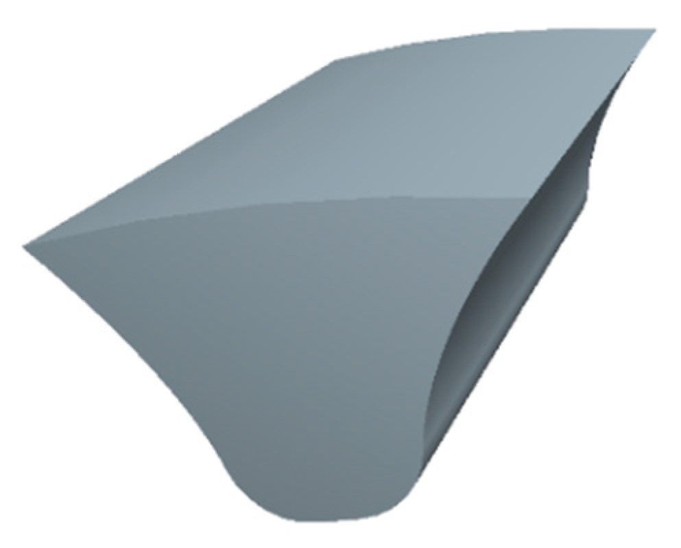
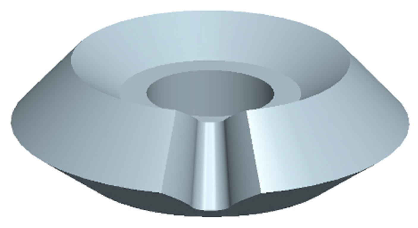
The alveolar surface is established by the spherical involute equation and the basic geometrical data of the sample straight bevel gear, and the alveolar entity is constructed by solidifying, as shown in Figure 1. The gear hub and cogging are imported into the assembly environment and the gear hub is cut by the cogging, as shown in Figure 2. Through rotation copying the tooth spaces, the full gear geometry model is accomplished. Figure 3 shows an assembly of two full 3D straight bevel gears’ geometry.
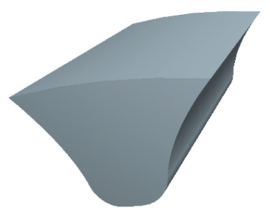
Figure 1.
Alveolar entity.
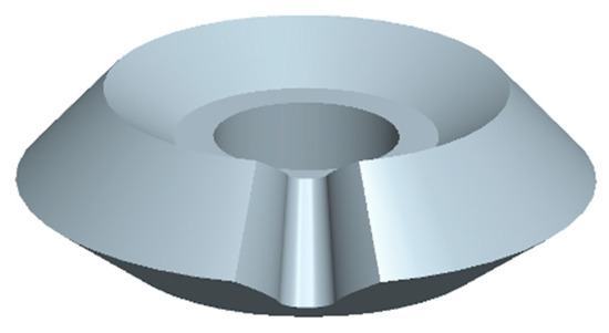
Figure 2.
Gear hub cut by the cogging.
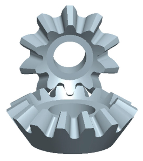
Figure 3.
Assembly of two full 3D straight bevel gears’ geometry.
3. Establishment of Finite Element Models
The finite element model of a straight bevel gear pair is performed with Solid45 (8-node isoparametric hexahedron element). The material is 40 Cr steel with the properties of Young’s modulus E = 2.1 × 10⁵ MPa and Poisson’s ratio μ = 0.3. The friction coefficient between two gears is 0.2 and the applied torque T = 50 Nm.
The developed approach for the finite element models is established as follows:
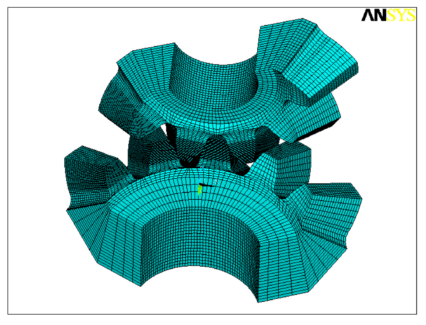
Step 1: The 3D geometrical models with the format of IGES are imported into ANSYS. Each tooth is divided into five subvolumes by auxiliary intermediate surfaces, as shown in Figure 4.
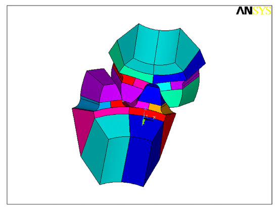
Figure 4.
Subvolumes of meshing tooth pairs.
Step 2: In the three gear teeth in contact analysis, there are 30 elements in profile direction and 20 elements in longitudinal direction. In the other gear teeth, there are only 5 elements in profile direction and 20 elements in longitudinal direction, as shown in Figure 5.
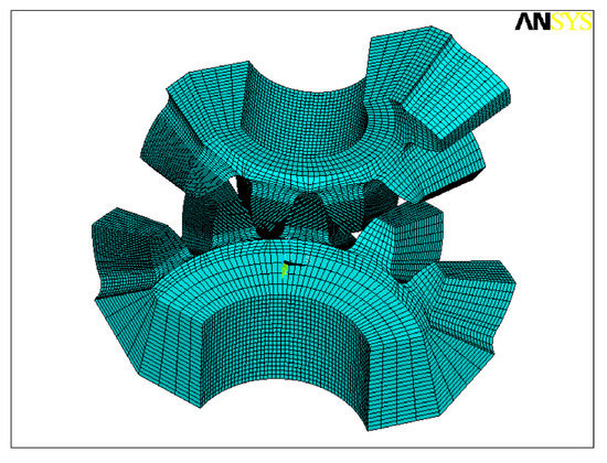
Figure 5.
Mesh-dividing model of meshing tooth pairs.
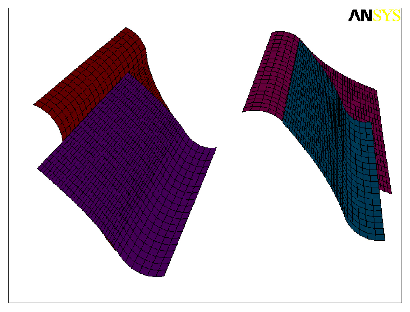
Step 3: Setting contact pairs for the gears. Contact pairs (a contact pair consists of a target surface and a contact surface) are defined in the contact position. Generally, the surface which has larger curvature will be chosen as the contact surface, thus the tooth surface of the pinion is picked as the contact surface and the tooth surface of the gear is defined as the target surface. In Figure 6, two contact pairs are shown when two pairs of teeth are in contact at the same time. By deleting or adding a contact pair, the simulation of single-tooth pair meshing or multi-tooth pairs meshing can be achieved.

Figure 6.
Definition of contact pairs when two tooth pairs are in contact.
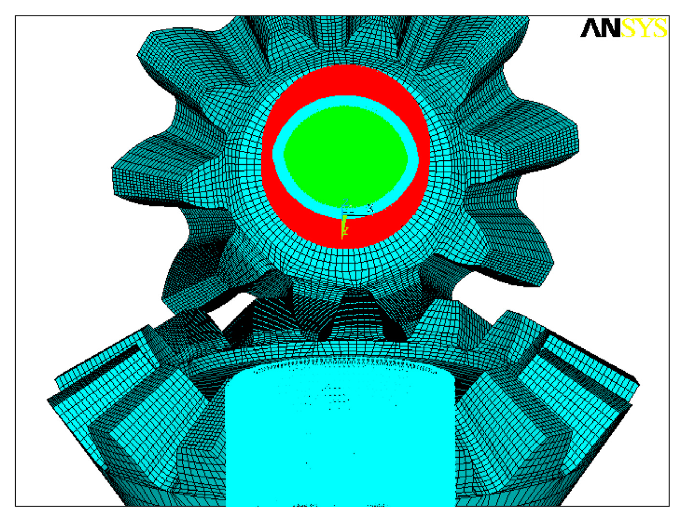
Step 4: Setting of boundary conditions and loads is achieved in the two local cylindrical coordinate systems, as shown in Figure 7. The following ideas are approved:
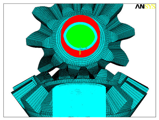
Figure 7.
The boundary conditions and loads of the driving pinion and the driven gear.
- (i)
- Nodes on the bottom rim of the driven gear are fixed.
- (ii)
- For the nodes on the bottom rim of the driving pinion, the radial and axial degrees of freedom are considered as fixed, and only the rational degree of freedom is set as free and coupled.
- (iii)
- The effect of force F at every node on the bottom rim of the driving pinion in the rotational direction on the pinion is equal to that of working torque T on the pinion. The force F is defined as the following:
Step 5: The simulation in the whole meshing cycle can be achieved through rotating the straight bevel gears.
4. Determination of the Meshing Interval for Investigation
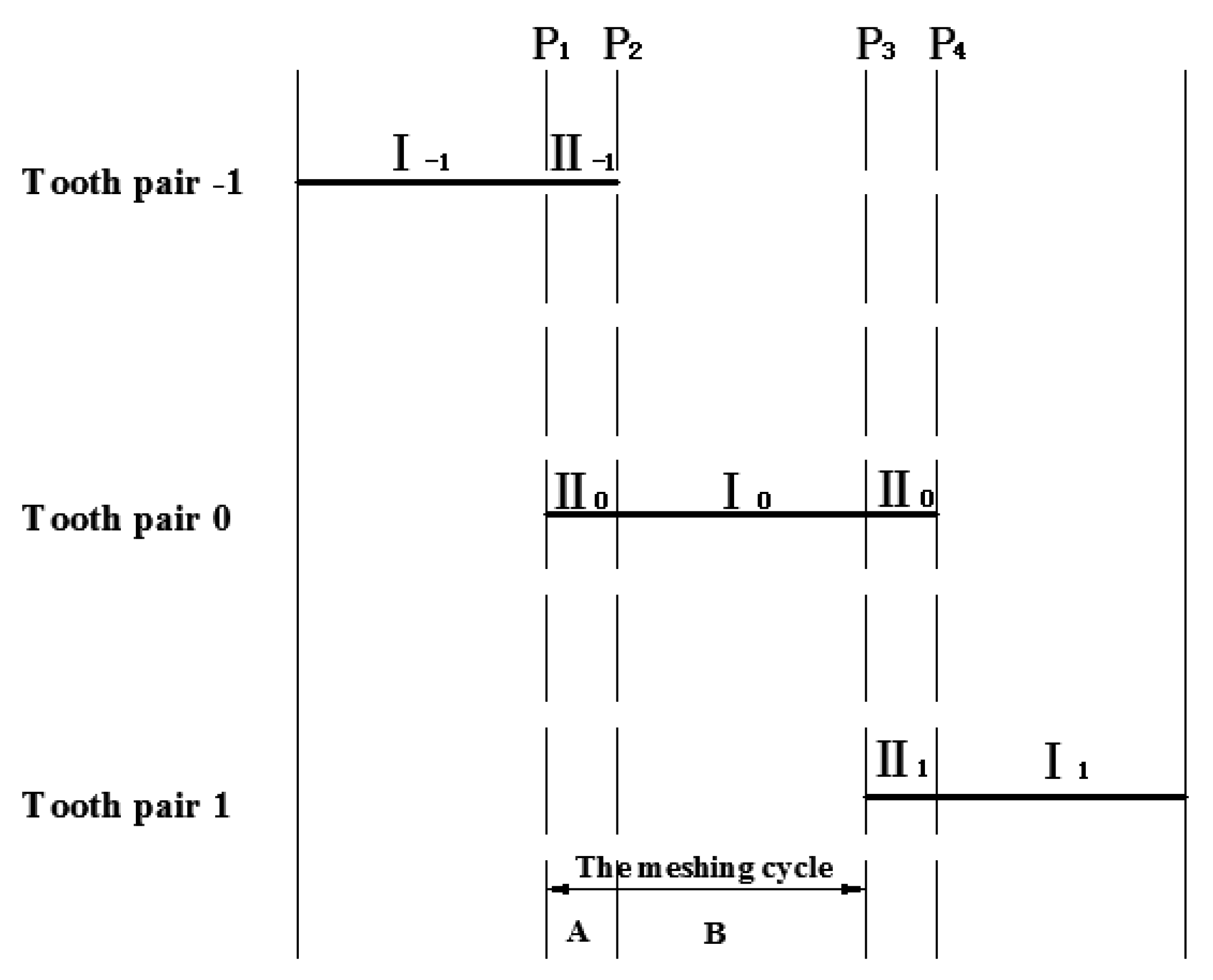
The basic meshing characteristic of loaded straight bevel gear drives is the periodical change of the meshing tooth pairs, as shown in Figure 8. In Figure 8, three pairs of teeth, named tooth pair −1, 0, +1, respectively, are defined to describe the meshing process. At the beginning, tooth pair −1 bears all load in the single pair tooth contact zone I. When reaching the transferring point P1, tooth pair 0 enters mesh so that the total load is shared by both tooth pair −1 and tooth pair 0 in the double pair tooth contact zone II. When transferring point P2 is reached, tooth pair −1 exits out of mesh. At the same time, the total load is suddenly transmitted to tooth pair 0 and the single pair tooth contact zone I for tooth pair 0 begins. As with the cycle, the load and motion will be transmitted from tooth pair 0 to tooth pair + 1.
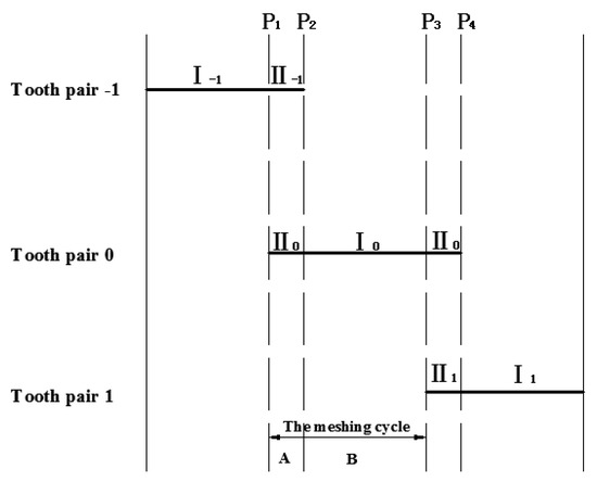
Figure 8.
Illustration of gear mesh.
As a result, a whole meshing cycle contains a single pair tooth contact zone I and a double pair tooth contact zone II. In this paper, a whole meshing cycle (A and B in Figure 8) is chosen for investigation. The transferring points P1 and P3 are selected as the critical points at the beginning and the end of a meshing cycle in the analysis, respectively.
5. Selection of Alignment Errors
As shown in Figure 9, four basic types of alignment errors can be defined as follows:
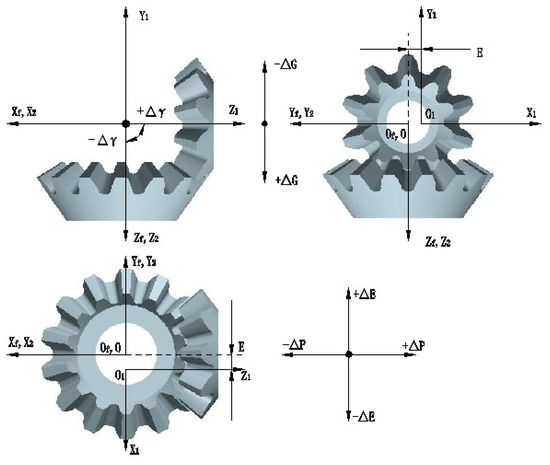
Figure 9.
Illustration of alignment errors.
- (i)
- Δγ is defined as the change of crossing angle.
- (ii)
- ΔP is defined as the axial displacement of the pinion.
- (iii)
- ΔG is defined as the axial displacement of the gear.
- (iv)
- ΔE is defined as the change center distance of the assembling straight bevel gears.
The values of alignment errors are shown in Table 2 and Table 3. The principles of choosing the values of alignment errors are as follows: when the value of alignment errors is less than zero, the large negative value will cause the occurrence of tooth surface interference. Therefore, the negative values of alignment errors should not be too large. When the value of alignment errors is larger than zero, the large positive value will make the contact ratio of the gear decrease greatly. Especially when ΔG = 0.1 or ΔP = 0.1, ends engaging between the teeth of straight bevel gears will occur, which causes contact stress on tooth surfaces to increase significantly. Furthermore, there are combined alignment errors existing in the practical assembly of gears which will produce greater influence on the meshing performance of the straight bevel gear pair. Therefore, we chose the values of alignment errors in Table 2 and Table 3 to discuss the influence of alignment errors on the gear drives. When the gears are in standard installation, the values of alignment errors are zero.
Table 2.
The values of single alignment error.
Table 3.
The values of combined alignment errors.
6. Results and Discussion
6.1. Influence of Single Alignment Error on the Gear Mesh
6.1.1. Influence of Single Alignment Error on the Contact Area
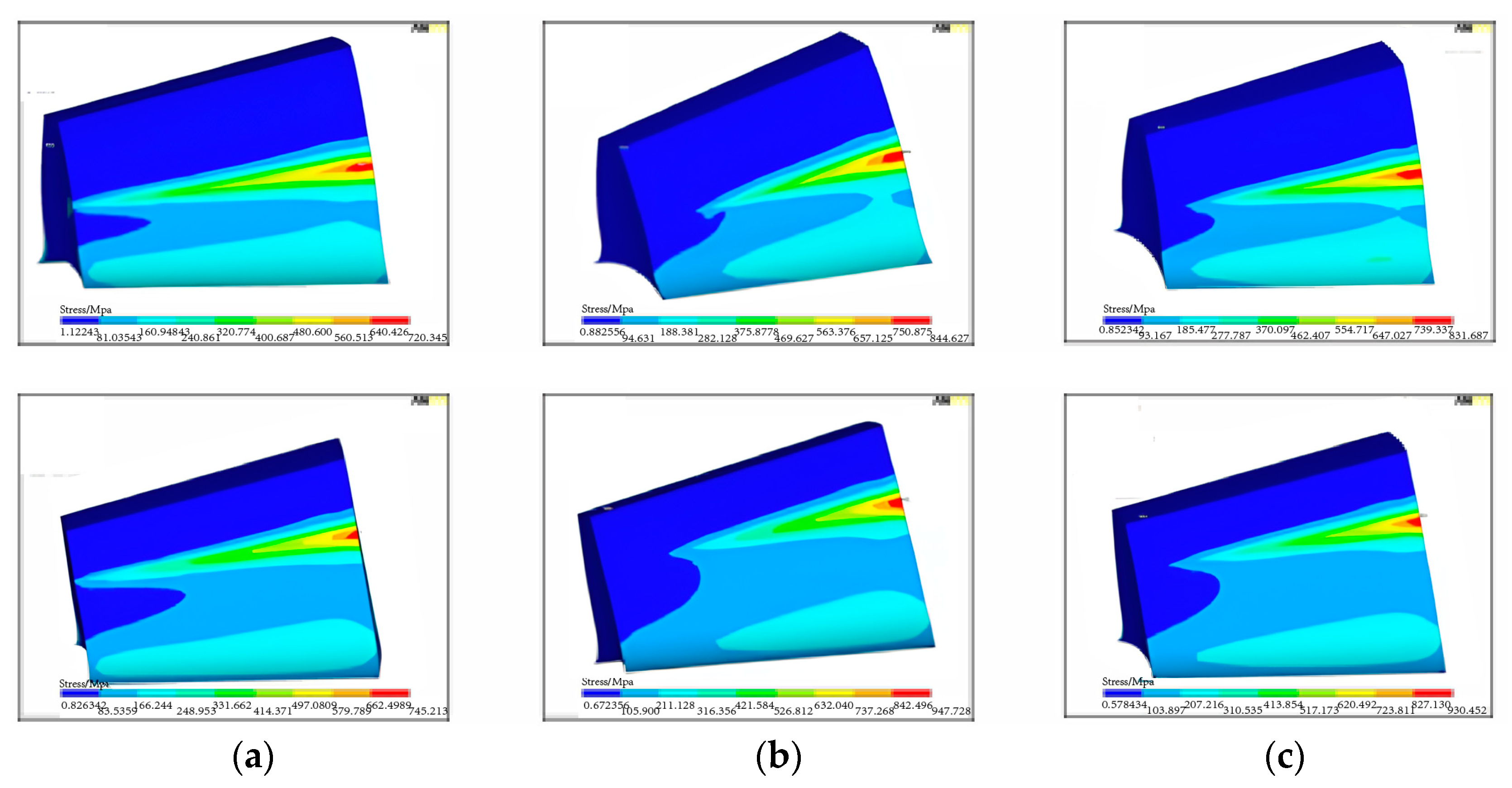
In this paper, the contact area of the working tooth pair at the pitch cone is investigated. Figure 10 presents the distribution of contact stress on the tooth surface for the straight bevel gears with the different single alignment error. As shown in Figure 10a, the contact stress along the longitudinal direction of the contact tooth pair is linear when the gears are in standard installation. Furthermore, contact stress is higher at the heel of the tooth. In Figure 10b, when ΔP = 0.1, the contact position moves to the heel of the tooth and the length of contact line along the longitudinal direction decreases. From Figure 10c, it can be seen that the contact position moves to the heel of the tooth and the length of contact line decreases when ΔG = 0.1. By comparing Figure 10d with Figure 10e, it can be seen that the contact position moves to the heel of the tooth when ΔE = −0.02 and it moves to the toe of the tooth when ΔE = 0.02. Moreover, the length of contact line decreases when ΔE = −0.02 or ΔE = 0.02. As shown in Figure 10f, when Δγ = 0.5, the contact area of the tooth pair is basically the same as that in the standard installation. Therefore, it can be concluded that the length of contact line decreases under the single alignment error ΔP, ΔG, and ΔE, and the contact area of the tooth pair is not sensitive to the alignment error Δγ.
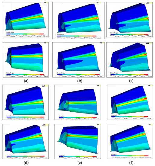
Figure 10.
Distribution of contact stress on tooth surface for the pinion (top) and the gear (bottom) with the different single alignment error. (a) ΔP = 0, (b) ΔP = 0.1, (c) ΔG = 0.1, (d) ΔE = −0.02, (e) ΔE = 0.02, (f) Δγ = 0.5.
6.1.2. Influence of the Single Alignment Error on the Transmission Error
The transmission error is the difference between the angle displacement of gears in reality and that in theory. Since the nodes on the bottom rim of the driven gear are fixed and the rational degree of freedom of the nodes on the bottom rim of the driving pinion is set as free, so the angle displacement of the bottom rim of the driven gear is zero. Therefore, the angle displacement of the bottom rim of the pinion is used to represent the transmission error in this paper. The angle displacement of the bottom rim of the pinion can be calculated using Equation (3) [17]:
where: δ is the circumferential displacement of the nodes on the bottom rim of the pinion under load, rd is the radius of the bottom rim of the pinion, and ϕ1 is the rotation angle of the driving pinion.
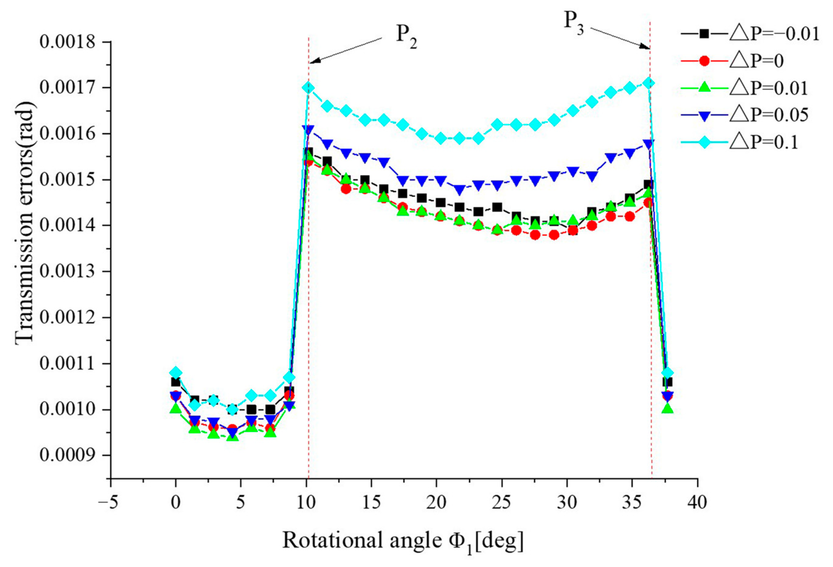
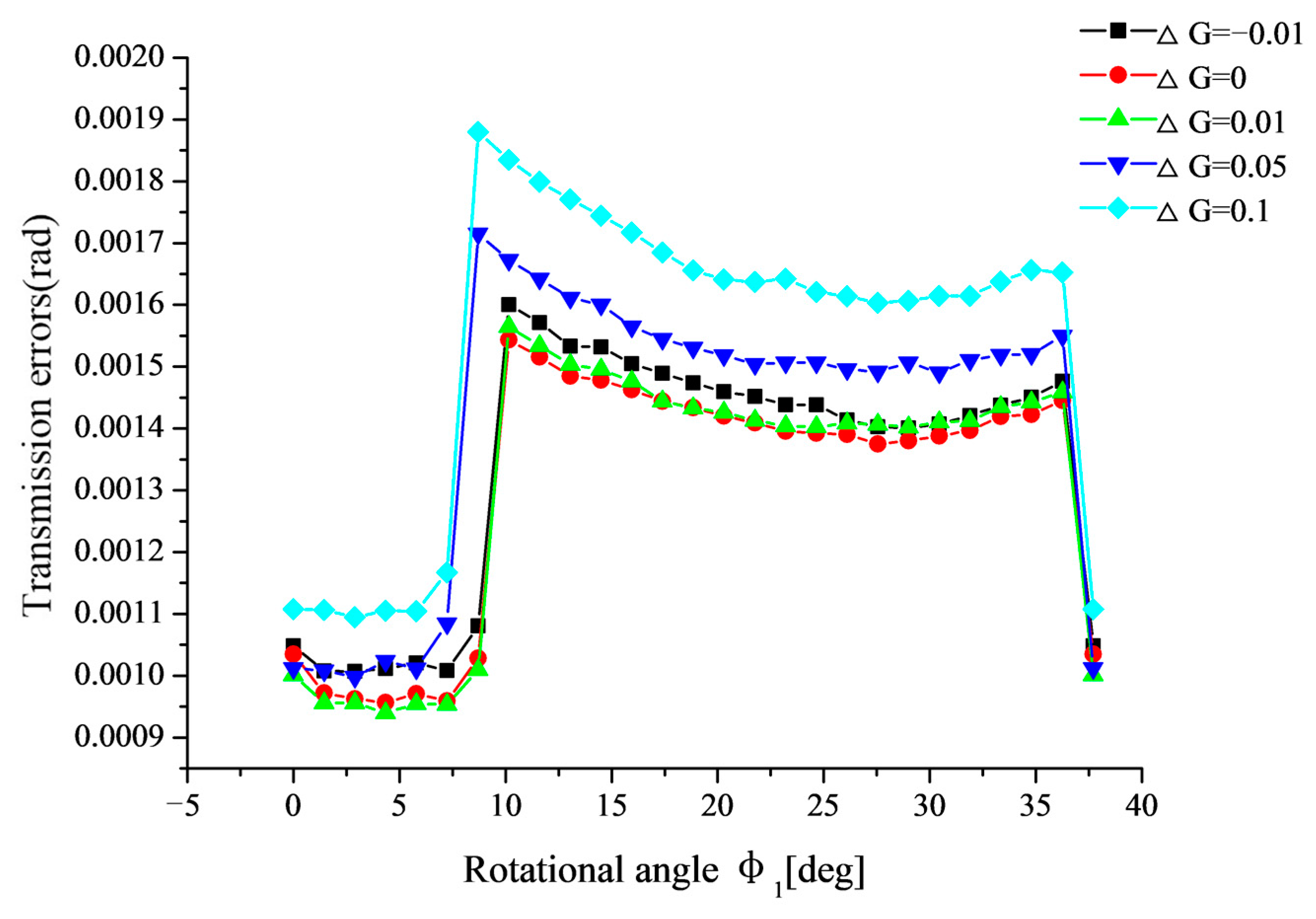
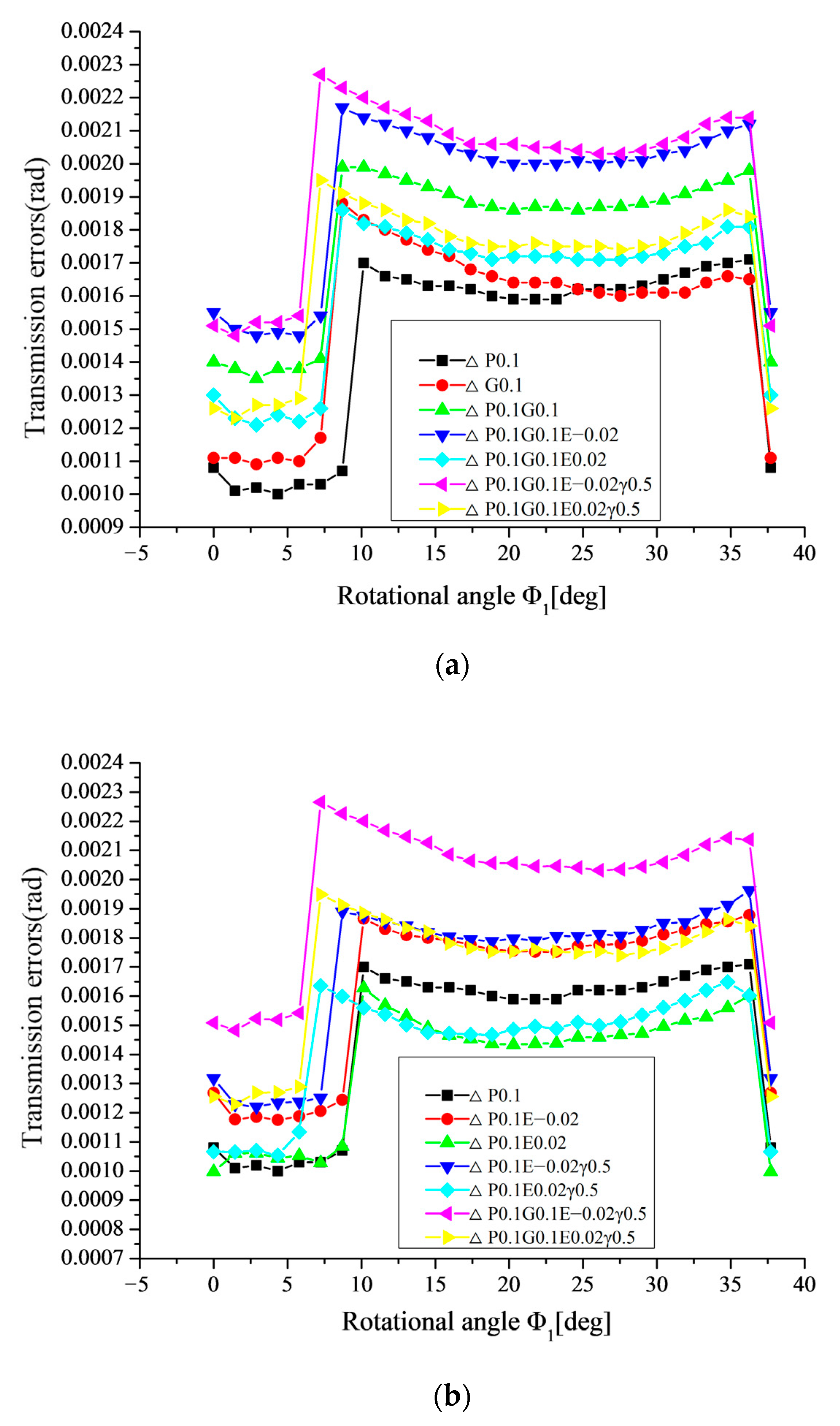
Figure 11, Figure 12, Figure 13 and Figure 14 show the variation of transmission errors in the meshing cycle with four basic types of alignment errors. It can be seen from Figure 11 and Figure 12 that the transmission error gradually increases with the increasing of ΔP or ΔG in the meshing cycle. This is because the length of contact line gradually decreases with the increasing of ΔP or ΔG, as shown in Figure 10b,c, respectively. It can be also seen from Figure 11 and Figure 12 that ΔP has a more significant effect on the transmission error at the transferring point P3 and ΔG has a more significant effect on the transmission error at the transferring point P2.
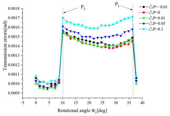
Figure 11.
Variation of transmission error in the meshing cycle with different ΔP.

Figure 12.
Variation of transmission error in the meshing cycle with different ΔG.
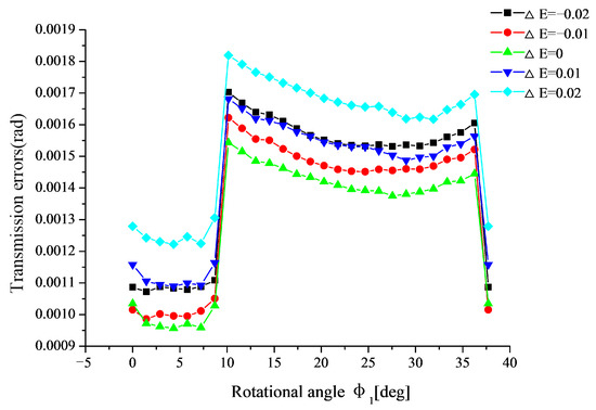
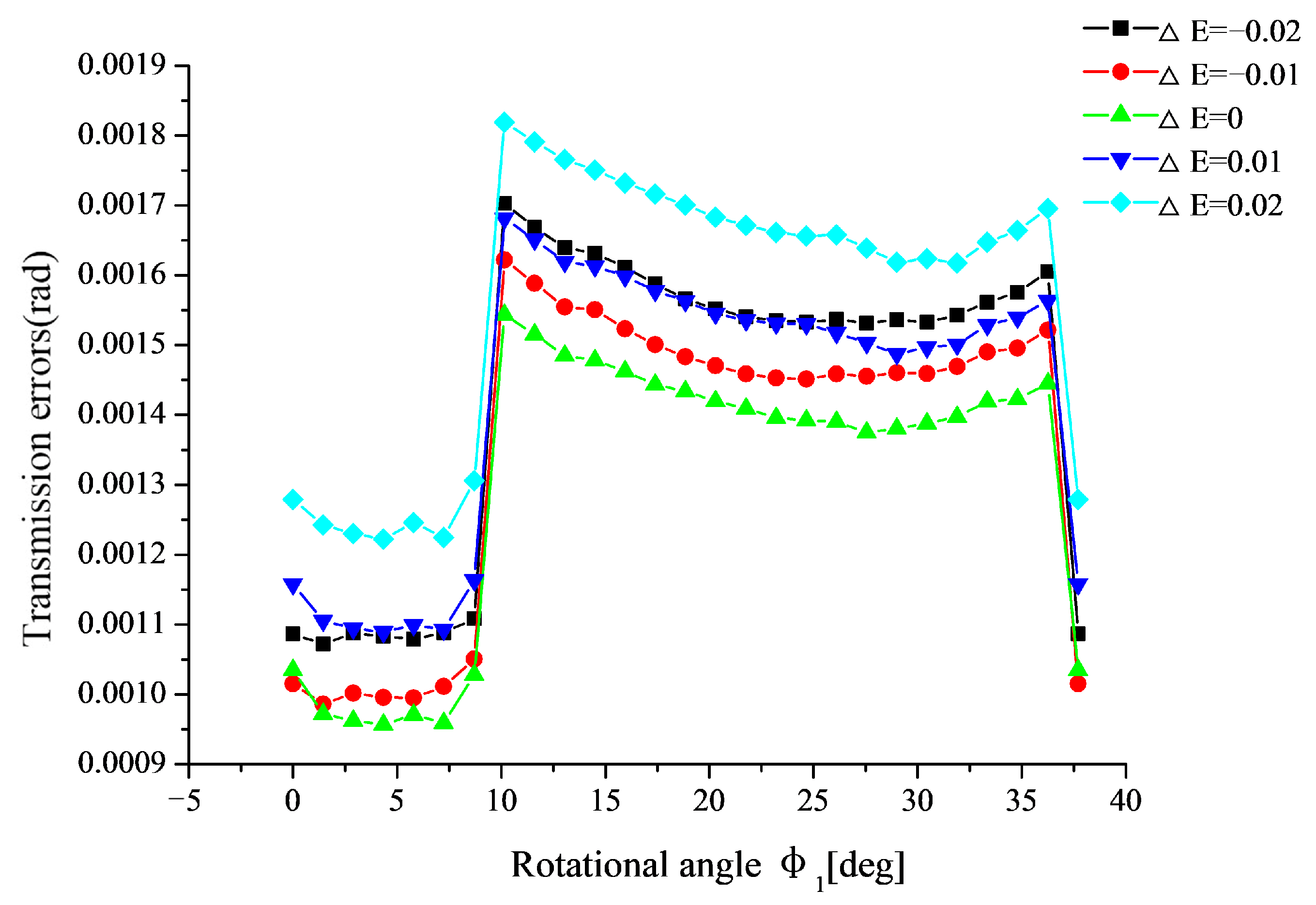
Figure 13.
Variation of transmission error in the meshing cycle with different ΔE.
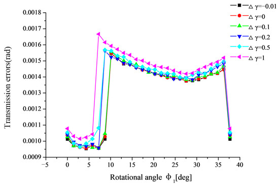
Figure 14.
Variation of transmission error in the meshing cycle with different Δγ.
From Figure 13, it can be seen that the transmission errors increase with the increasing of ΔE. Furthermore, the influence of ΔE > 0 on the transmission error is larger than that, when ΔE < 0. The main reason for this is that, when ΔE > 0, the stress concentration at the toe is more serious than that at the heel of the straight bevel gear tooth, when ΔE < 0, as shown in Figure 10d,e, respectively.
It can be seen from Figure 14 that the transmission errors increase slowly with the increasing of Δγ, i.e., the transmission error is not sensitive to Δγ. The main reason for this is that the length of contact line decreases slowly with the increasing of Δγ, as shown in Figure 10f.
In short, the transmission error is sensitive to the single alignment error ΔP, ΔG, and ΔE. Therefore, the single alignment error ΔP, ΔG, and ΔE should be controlled in the practical assembly of straight bevel gears to ensure the straight bevel gear pair meshing smoothly.
6.1.3. Influence of Single Alignment Error on the Vibration and Noise of Gear Drives
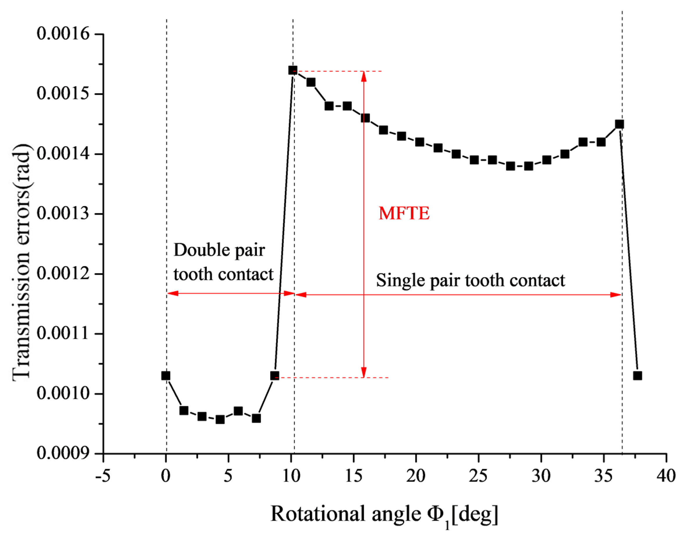
In this paper, the maximum fluctuation of transmission errors (MFTE) of the gear pair is used to assess the vibration level of gear drives, as shown in Figure 15. The higher the MFTE of the gear pair, the more dramatic the vibration of gear drives. Meanwhile, Equation (4) [10] is used to evaluate the relative size of noise of gear drives with different types of alignment errors qualitatively.
where: ω2(e)rms is the root mean square of the signals (in rms) caused by the transmission errors with some kind of alignment error, while ω2(0)rms is the root mean square of the signals (in rms) caused by the transmission errors under standard installation; is the value of transmission error at the engagement position i with some kind of alignment error; is the value of transmission error at the engagement position i under standard installation; engagement position i and engagement position i − 1 are two successive engagement positions.

Figure 15.
Variation of transmission error in the meshing cycle under standard installation.
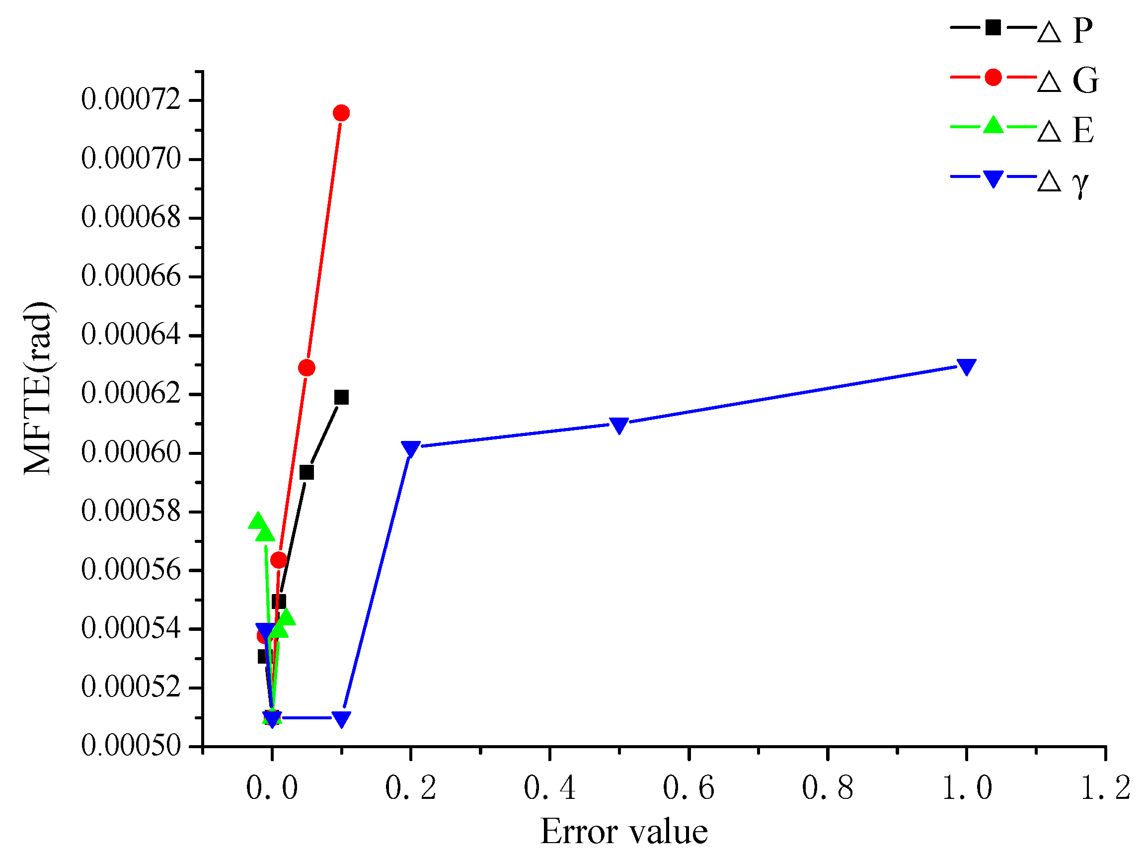
Figure 16 presents the variation of MFTE of straight bevel gear drives with different alignment errors. From Figure 16, it can be seen that MFTE increases dramatically with the increasing of ΔP, ΔG, and ΔE (ΔE < 0), but it increases slowly with the increasing of ΔE (ΔE < 0). It can be also seen from Figure 16 that MFTE increases slowly, when 0 < Δγ < 0.1 or Δγ > 0.2, but it increases sharply, when 0.1 < Δγ < 0.2. Therefore, it can be concluded that the alignment errors ΔP, ΔG, ΔE (ΔE < 0), and Δγ have great influence on MFTE. That is to say, the vibration of straight bevel gear drives is sensitive to the four basic types of alignment errors.
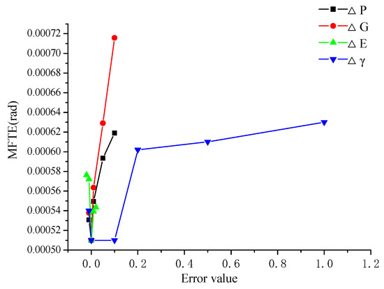
Figure 16.
Variation of MFTE with different alignment errors.
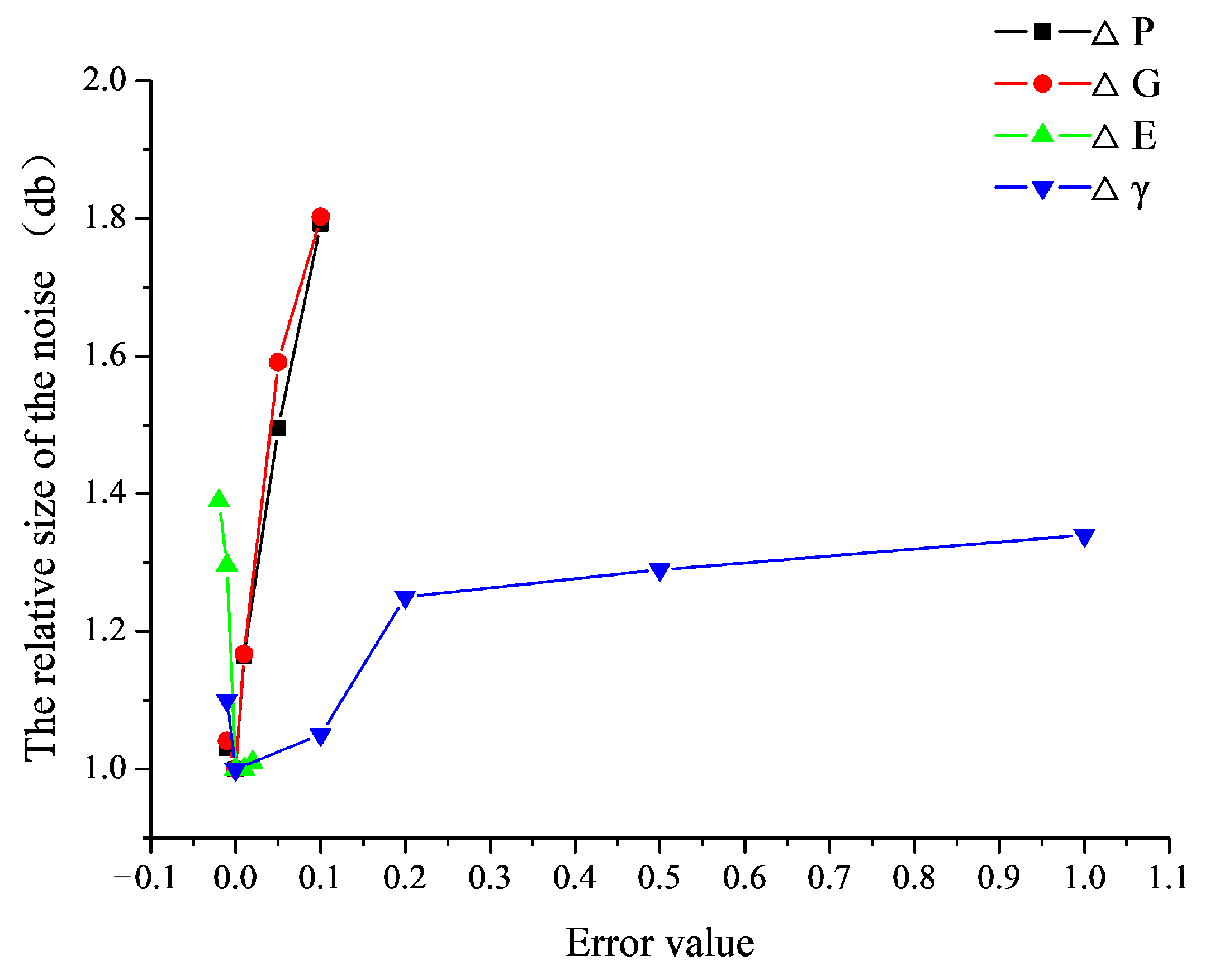
Figure 17 presents the variation of noise of straight bevel gear drives with different alignment errors. As shown in Figure 17, it can be concluded that the variation of noise of gear drives is basically in accordance with the variation of MFTE of gear drives with different alignment errors. The noise of straight bevel gear drives is sensitive to the four basic types of alignment errors ΔP, ΔG, ΔE (ΔE < 0), and Δγ. Therefore, it is important to control the alignment errors ΔP, ΔG, ΔE (ΔE < 0), and Δγ in the practical assembly of straight bevel gears to weaken the vibration and noise of the straight bevel gear drives.
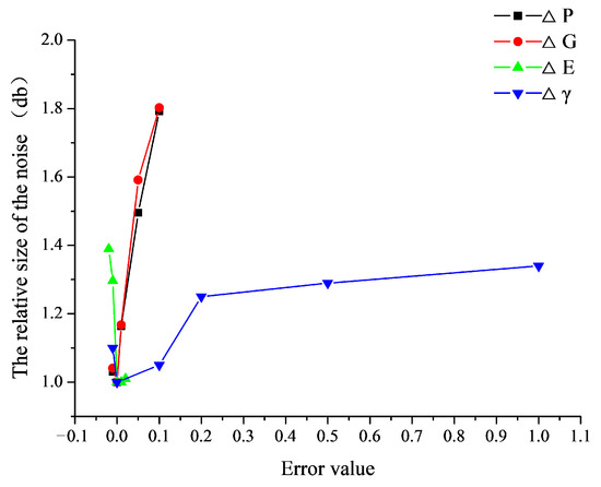
Figure 17.
Variation of noise of gear drives with different alignment errors.
6.2. Influence of Combined Alignment Errors on the Gear Mesh
6.2.1. Influence of Combined Alignment Errors on the Contact Zone
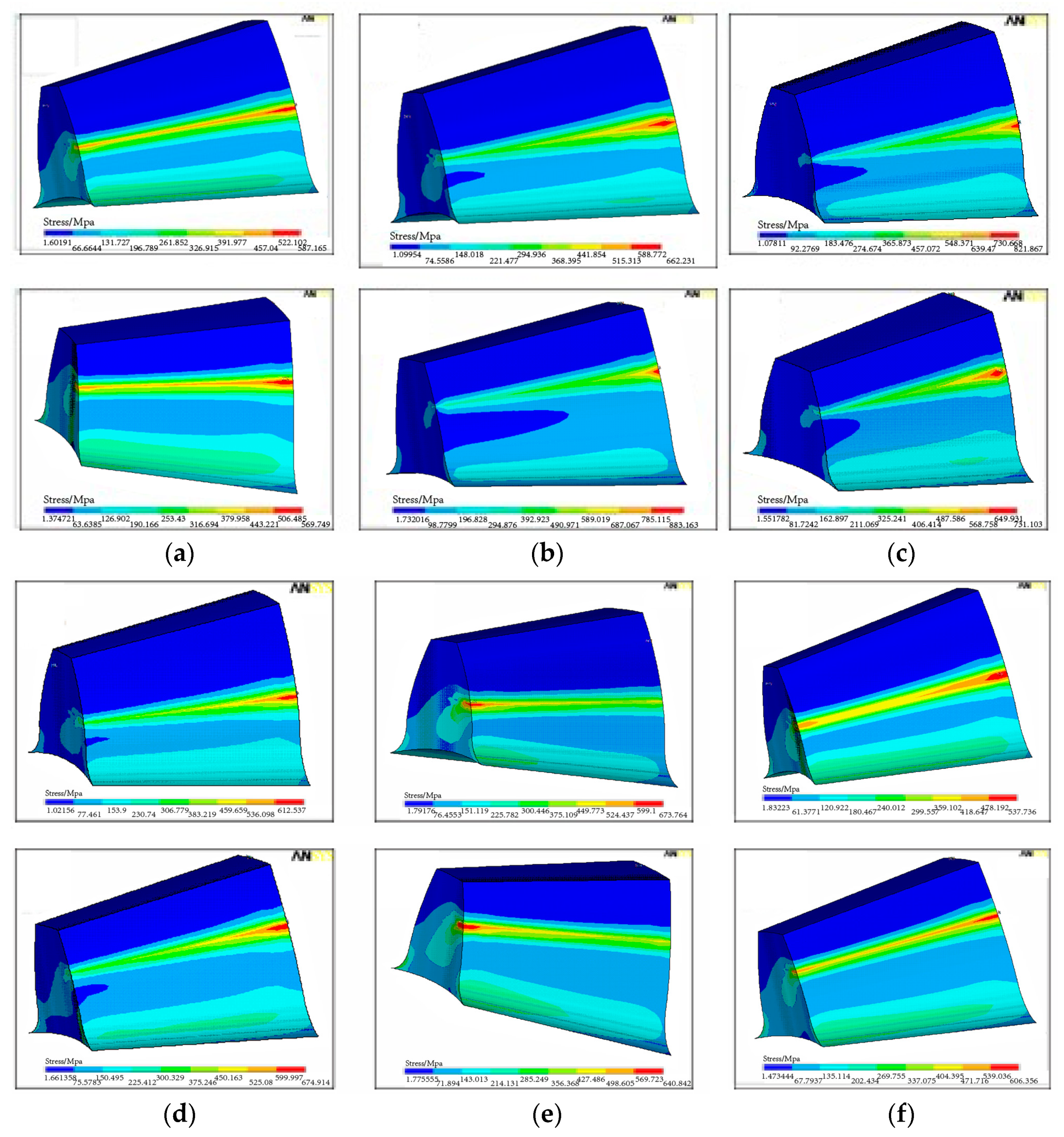
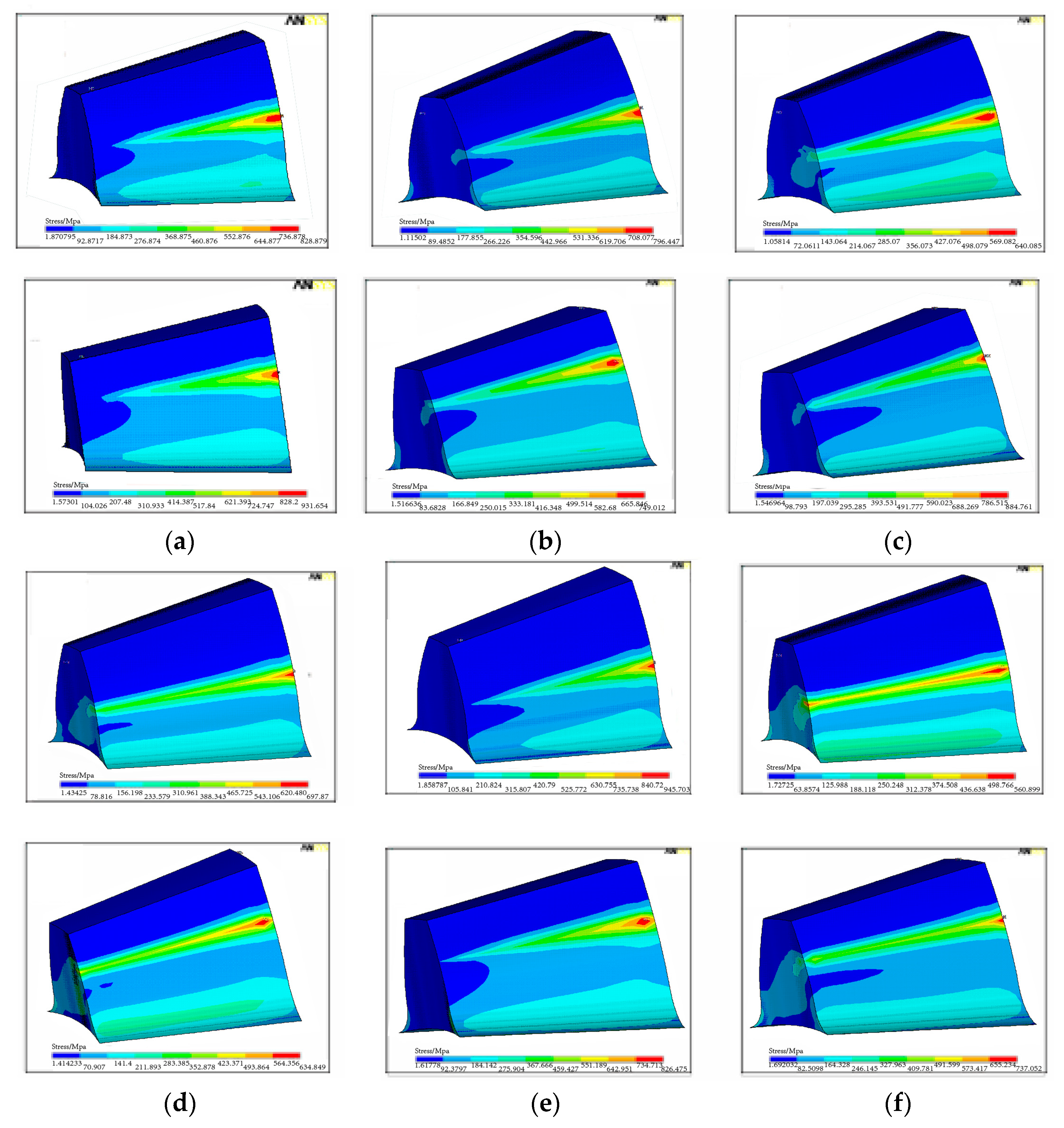
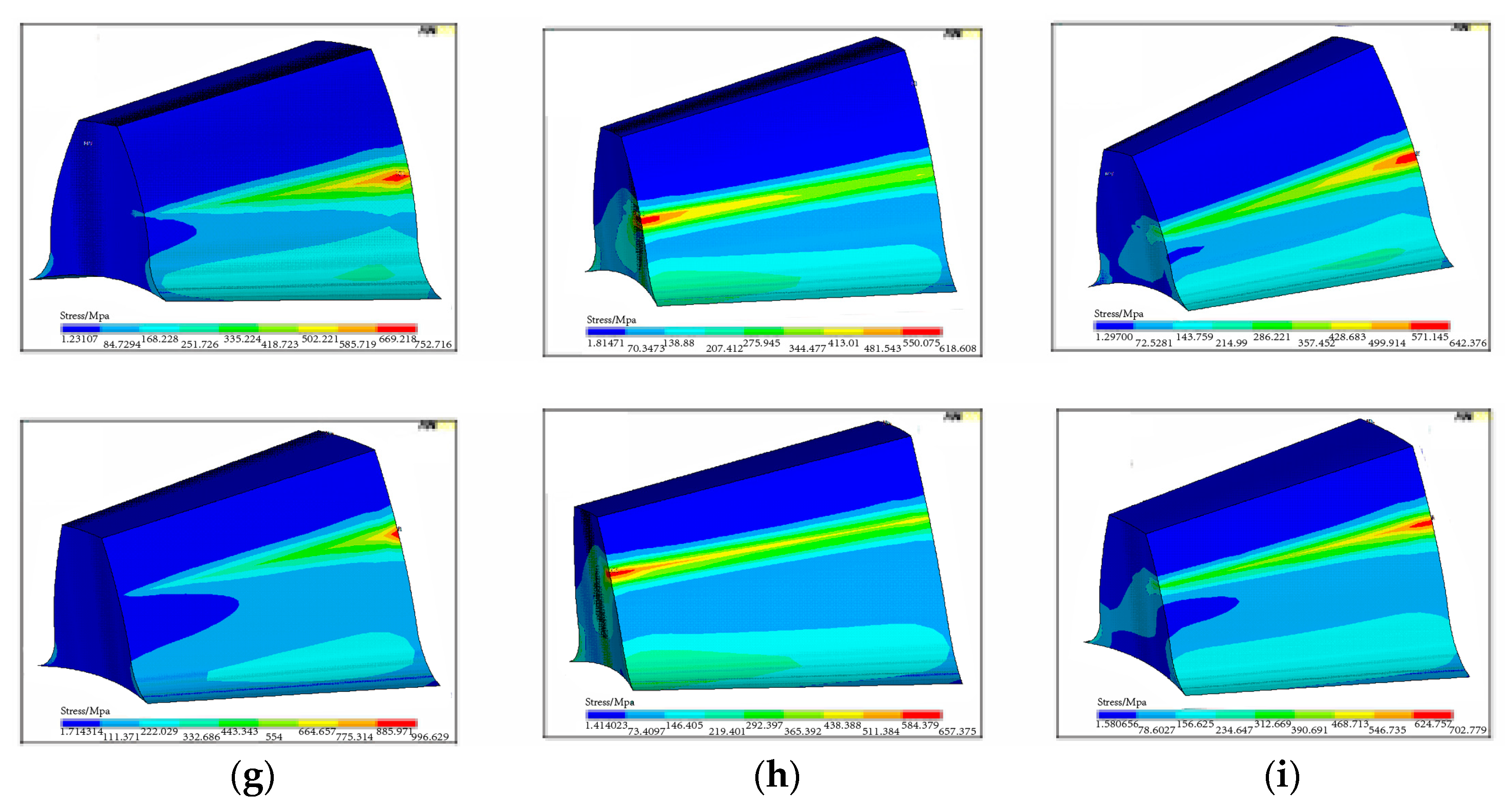
Figure 18 and Figure 19 show the distribution of contact stress on the tooth surface for the straight bevel gears with combined alignment errors. As shown in Figure 18a,e,g, it can be seen that the length of contact line along the longitudinal direction decreases significantly and the contact stress concentrates on each heel of the pinion tooth and the gear tooth, when ΔP = 0.1 and ΔG = 0.1, ΔP = 0.1 and ΔE = −0.02, ΔG = 0.1 and ΔE = −0.02. Therefore, the gear transmission will be less smooth when those combined alignment errors exist. As shown in Figure 18b,c,h,i, it can be seen that, when Δγ and one of ΔP, ΔG, ΔE combines, the teeth contact zone has little change compared with that in the single ΔP, ΔG, ΔE. By comparing Figure 18d,f with Figure 10b,c, it can be seen that the length of contact line along the longitudinal direction increases, when ΔP = 0.1 and ΔE = 0.02 or ΔG = 0.1 and ΔE = 0.02, which will make the transmission of straight bevel gears smooth.
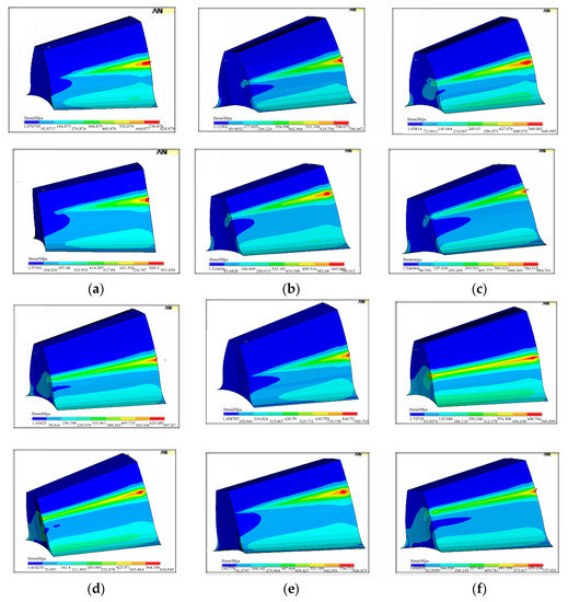

Figure 18.
Distribution of contact stress on tooth surface for the pinion (top) and the gear (bottom) with combined alignment errors. (a) ΔP = 0.1 and ΔG = 0.1, (b) Δγ = 0.5 and ΔG = 0.1, (c) Δγ = 0.5 and ΔP = 0.1, (d) ΔG = 0.1 and ΔE = 0.02, (e) ΔG = 0.1 and ΔE = −0.02, (f) ΔP = 0.1 and ΔE = 0.02, (g) ΔP = 0.1 and ΔE = −0.02, (h) Δγ = 0.5 and ΔE = 0.02, (i) Δγ = 0.5 and ΔE = −0.02.


Figure 19.
Distribution of contact stress on tooth surface for the pinion (top) and the gear (bottom) with combined alignment errors. (a) ΔP = 0.1, ΔG = 0.1 and ΔE = 0.02, (b) ΔP = 0.1, ΔG = 0.1 and ΔE = −0.02, (c) ΔP = 0.1, ΔG = 0.1 and Δγ = 0.5, (d) ΔG = 0.1, ΔE = 0.02, Δγ = 0.5, (e) ΔG = 0.1, ΔE = −0.02 and Δγ = 0.5, (f) ΔP = 0.1, ΔE = 0.02 and Δγ = 0.5, (g) ΔP = 0.1, ΔE = −0.02 and Δγ = 0.5, (h) ΔP = 0.1, ΔG = 0.1, ΔE = 0.02 and Δγ = 0.5, (i) ΔP = 0.1, ΔG = 0.1, ΔE = −0.02 and Δγ = 0.5.
By comparing Figure 19a,b with Figure 18a, it can be seen that the length of contact line along the longitudinal direction decreases dramatically when ΔP = 0.1, ΔG = 0.1, and ΔE = −0.02 compared with when ΔP = 0.1 and ΔG = 0.1. However, the length of contact line along the longitudinal direction increases when ΔP = 0.1, ΔG = 0.1, and ΔE = 0.02 compared with when ΔP = 0.1 and ΔG = 0.1. Lastly, it can be seen from Figure 19i that the most dangerous type of alignment errors is when ΔP, ΔG, ΔE < 0, and Δγ, because the length of contact line along the longitudinal direction decreases dramatically. By comparing Figure 18 and Figure 19 with Figure 10, it can be concluded that the alignment errors have a cumulative effect on the length of contact line. Furthermore, it has proven that the contact zone is not sensitive to the alignment error Δγ again from Figure 18a,d–g and Figure 19c–g with Figure 10.
6.2.2. Influence of Combined Alignment Errors on the Transmission Error
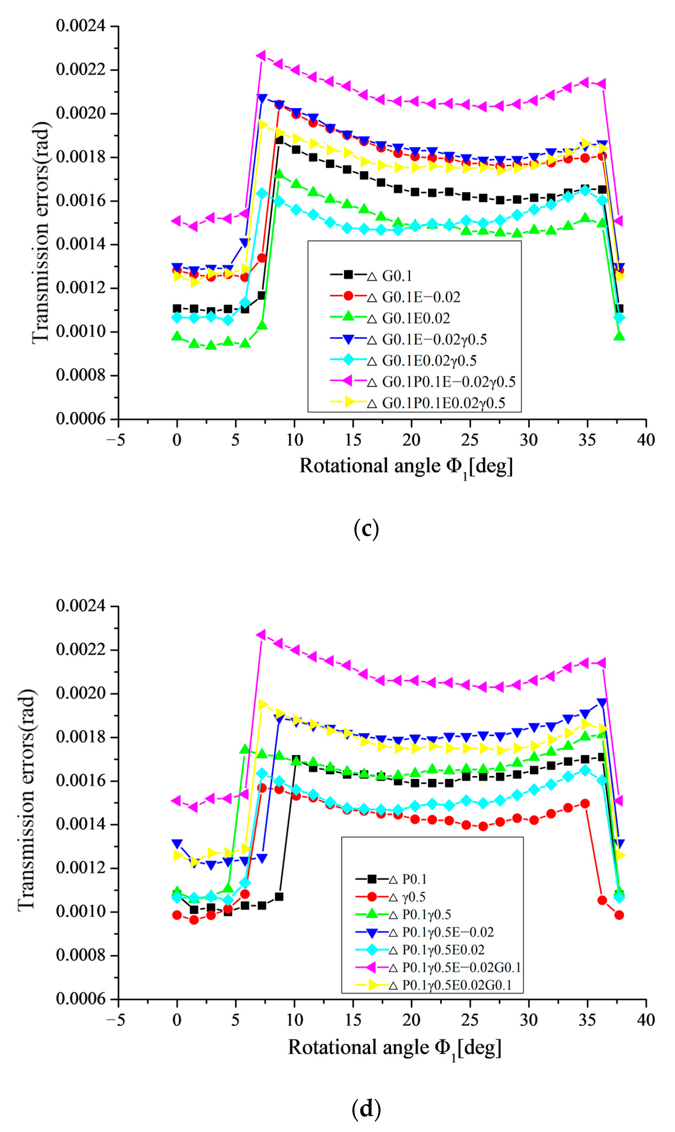
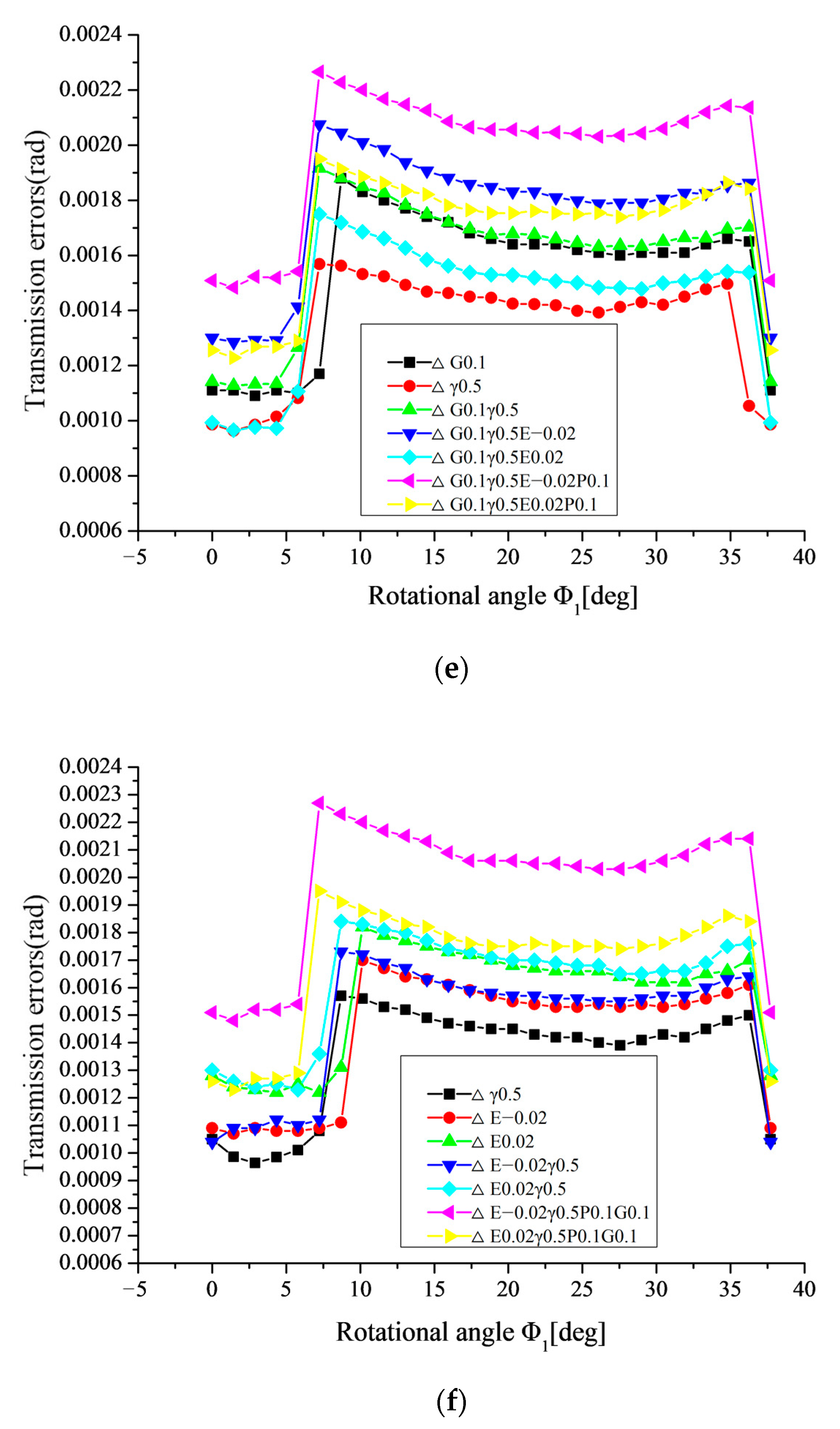
The transmission errors of the gear drive in the meshing cycle with combined alignment errors are presented in Figure 20. The results of the investigation are as follows:
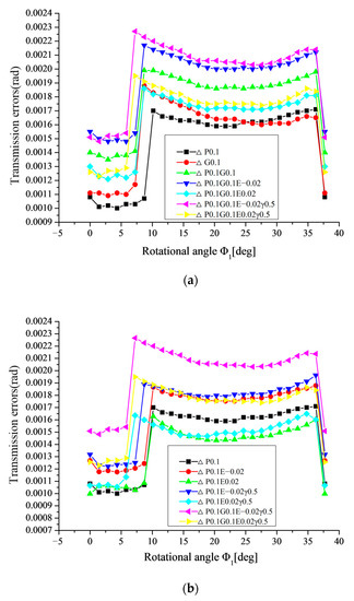
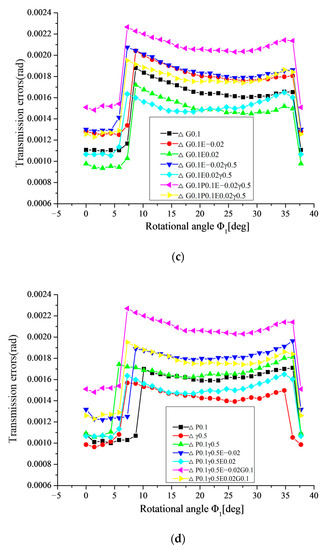
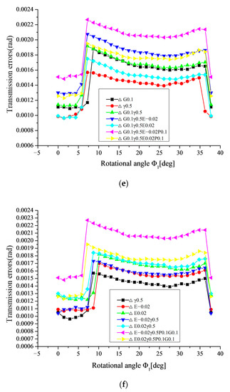
Figure 20.
Variation of transmission errors in the meshing cycle with combined alignment errors. (a) based on ΔP and ΔG, (b) based on ΔP and ΔE, (c) based on ΔG and ΔE, (d) based on ΔP and Δγ, (e) based on ΔG and Δγ, (f) based on ΔE and Δγ.
- (1)
- As shown in Figure 20a, it can be seen that, when ΔP and ΔG combine, the transmission error increases greatly in the whole meshing circle, compared with that in the single ΔP or ΔG.
- (2)
- As shown in Figure 20b, it can be seen that, when ΔP and ΔE (ΔE < 0) combine, the transmission error increases greatly in the whole meshing circle compared with that in the single ΔP. However, when ΔP and ΔE (ΔE > 0) combine, the transmission error decreases dramatically in the single pair tooth contact zone, compared with that in the single ΔP. However, the transmission error in the double pair tooth contact zone is basically in accordance with the single ΔP.
- (3)
- As shown in Figure 20c, it can be obtained that, when ΔG and ΔE < 0 combine transmission error increases greatly in the whole meshing circle compared with that in single ΔG. However, when ΔG and ΔE > 0 combine, the transmission error decreases dramatically in the whole meshing circle compared with that in single ΔG.
- (4)
- As shown in Figure 20d,e,f, it can be seen that, when Δγ and one of ΔP, ΔG, ΔE combines, the transmission errors are basically consistent compared with that in single ΔP, ΔG or ΔE. Therefore, it can be concluded that the transmission error is not sensitive to Δγ.
- (5)
- It can be seen from Figure 20 that it is the most dangerous type of alignment errors for increasing the transmission error dramatically, when ΔP, ΔG, ΔE (ΔE < 0) and Δγ.
- (6)
- The alignment errors have a cumulative effect on the length of contact line and the contact zone causing the change of gear stiffness. The reduction of the length of contact line will cause the decrease of gear stiffness. The transmission errors increase with the decreasing of gear stiffness.
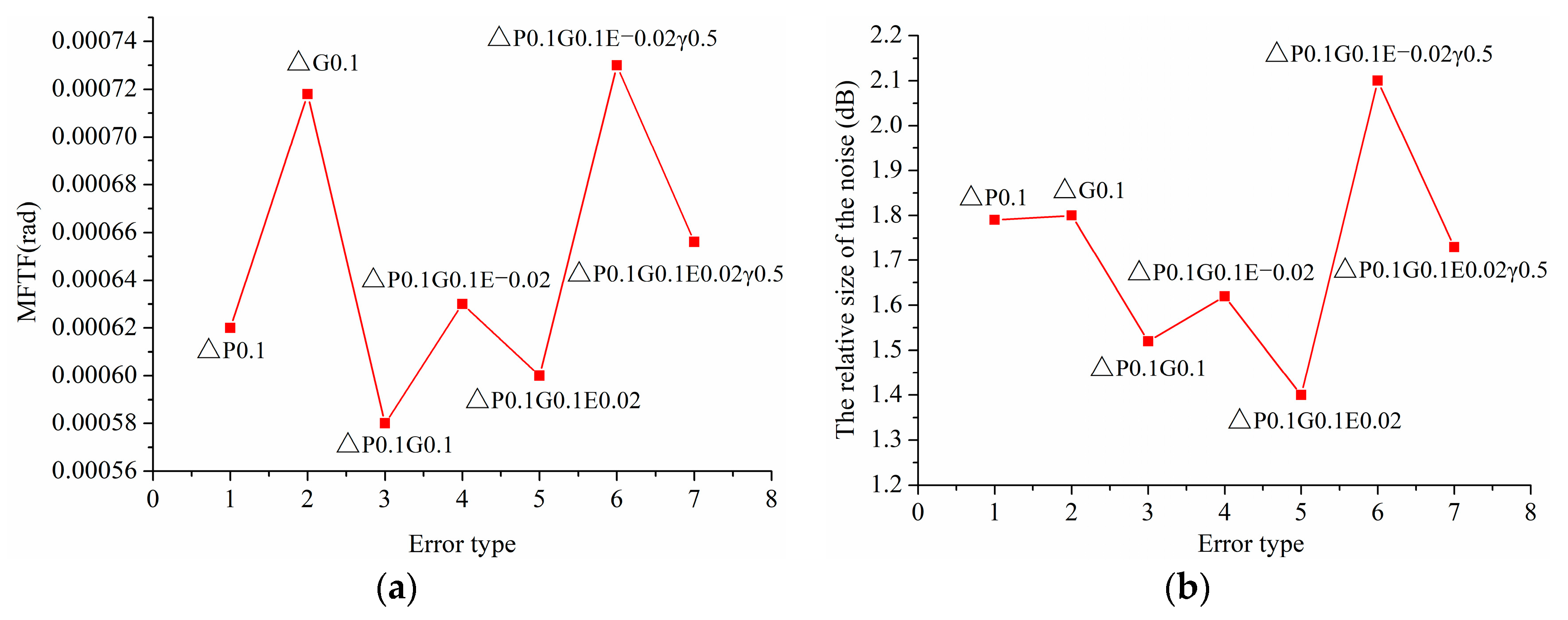
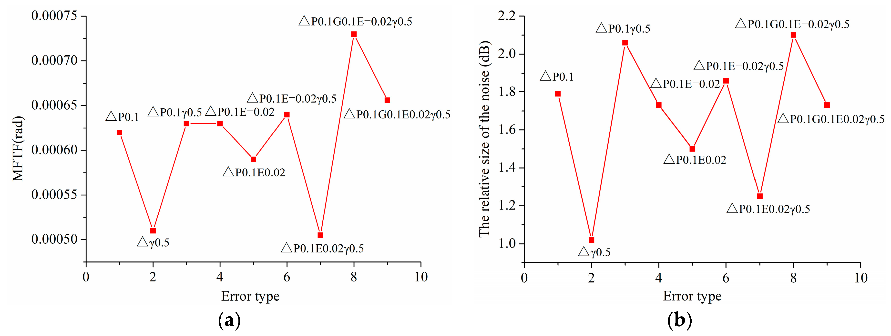
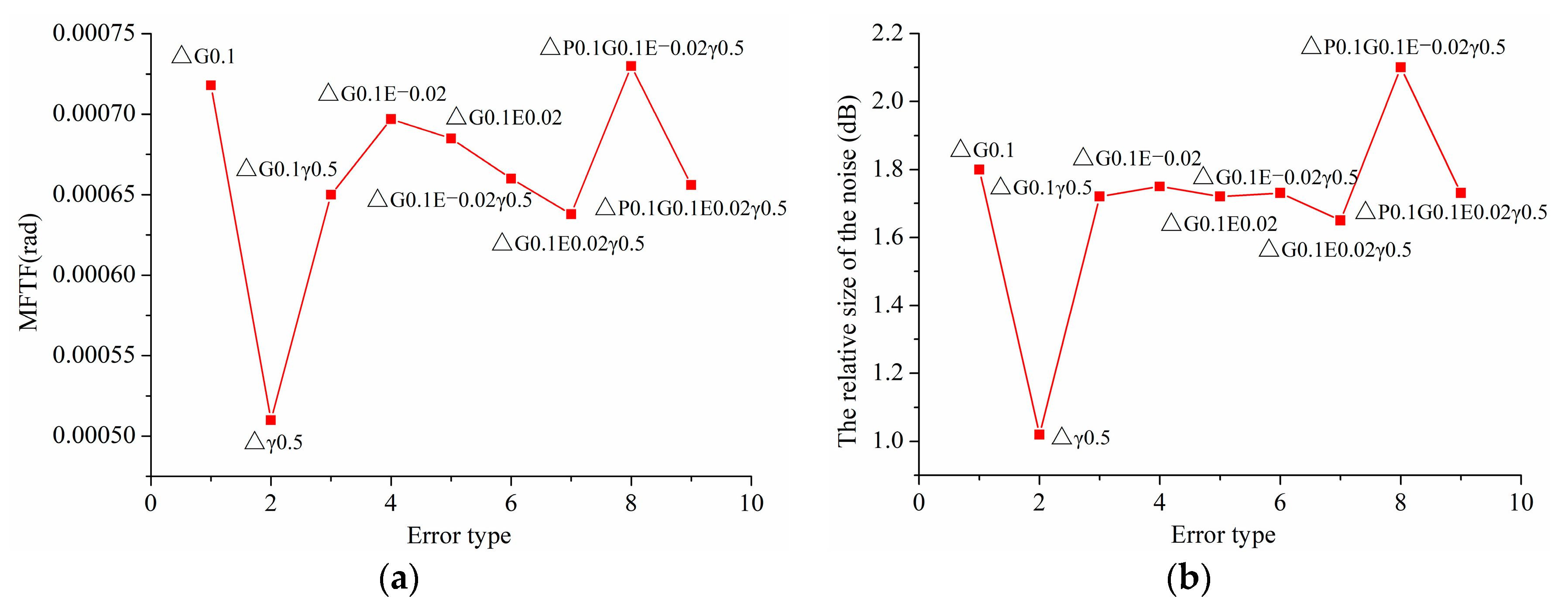
6.2.3. Influence of Combined Alignment Errors on the Vibration and Noise of Gear Drives
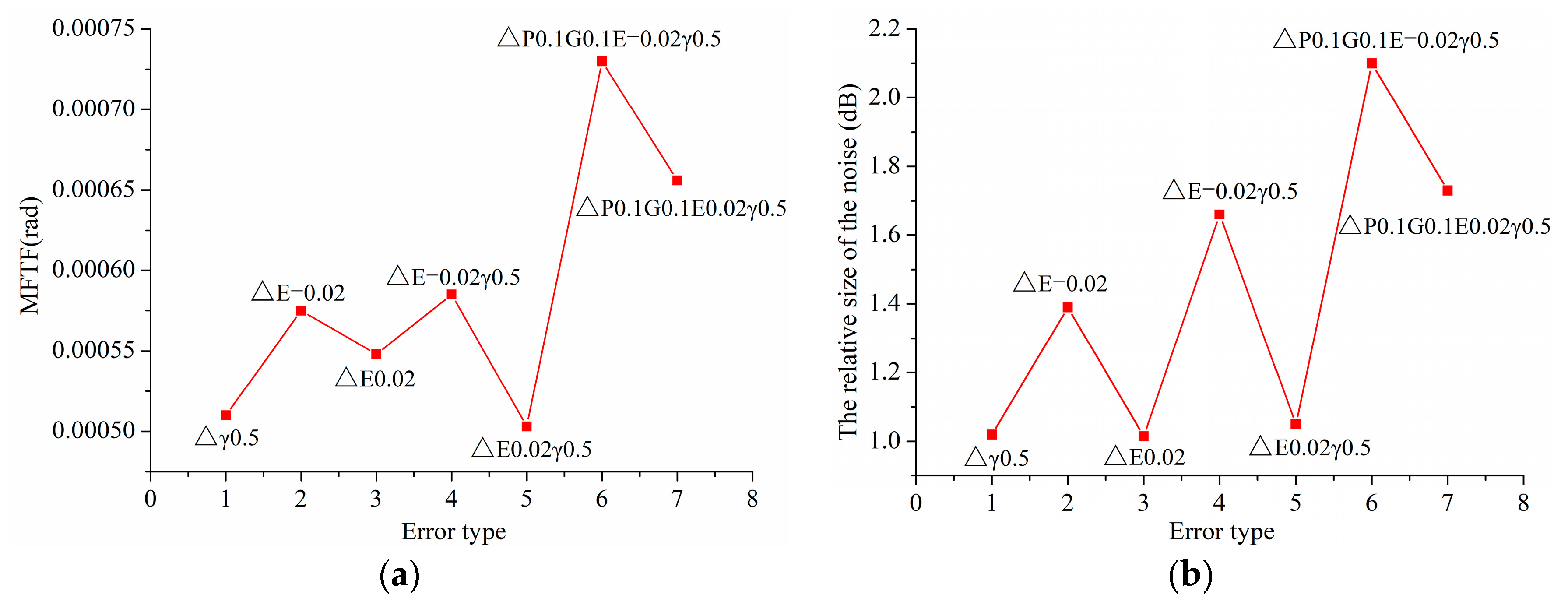
Figure 21, Figure 22, Figure 23 and Figure 24 present the vibration and noise of gear drives with combined alignment errors. As shown in Figure 21, it can be seen that the vibration and noise of gear drives with ΔP and ΔG decreases greatly compared with that with single ΔP or ΔG. Comparing Figure 18a with Figure 20a, it can be seen that, when ΔP and ΔG combine, the transmission error increases more in the double pair tooth contact zone, resulting in the reduction of the fluctuation of transmission error at the transferring point P2, and the reduction of the fluctuation of transmission error at the transferring point P2 leads to the decrease of the vibration and noise of gear drives.
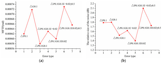
Figure 21.
(a,b) Variation of MFTE and Variation of noise of gear drives under combined alignment errors based on ΔP and ΔG, respectively.
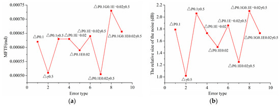
Figure 22.
(a,b) Variation of MFTE and Variation of noise of gear drives under combined alignment errors based on ΔP, ΔE and Δγ, respectively.
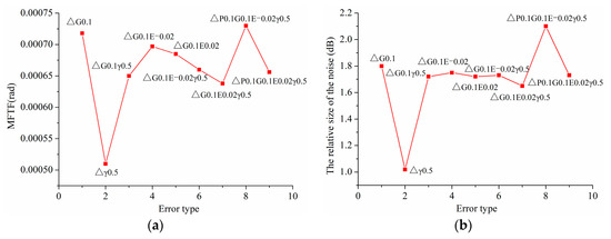
Figure 23.
(a,b) Variation of MFTE and Variation of noise of gear drives under combined alignment errors based on ΔG, ΔE and Δγ, respectively.
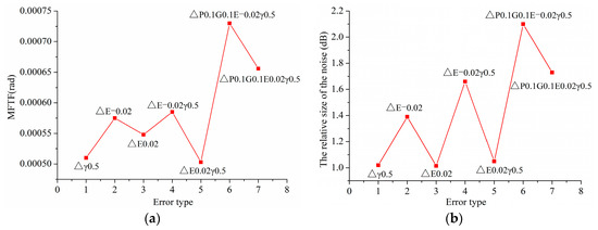
Figure 24.
(a,b) Variation of MFTE and Variation of noise of gear drives under combined alignment errors based on ΔE and Δγ, respectively.
From Figure 22, it can be seen that the changing trend of vibration and noise of gear drives with ΔP, ΔE, and Δγ is approximately consistent. Furthermore, the vibration and noise of gear drives with ΔP and ΔE (ΔE > 0) decreases dramatically, because the increase of the length of contact line along the longitudinal direction results in the increase of gear stiffness. As shown in Figure 23, it can be seen that the changing trend of vibration and noise of gear drives with ΔG, ΔE, and Δγ is basically consistent. Furthermore, the vibration and noise of gear drives with ΔG, ΔE, and Δγ decrease slightly compared with that with single ΔG.
As shown in Figure 24, it can be seen that the changing trend of vibration and noise of gear drives with ΔE and Δγ is almost consistent. Furthermore, the vibration of gear drives increases slightly, but the noise of gear drives with ΔE (ΔE < 0) and Δγ increases dramatically compared with that with single ΔE (ΔE < 0). From Figure 21, Figure 22, Figure 23 and Figure 24, it can be concluded that the most dangerous type of alignment errors for increasing the vibration and noise of gear drives dramatically is when ΔP, ΔG, ΔE (ΔE < 0), and Δγ.
7. Conclusions
- (1)
- The alignment errors will cause the straight bevel gear pair contacting at one end and gaping at the other end of the teeth and make the contact zone and the contact line of the straight bevel gear pair change greatly. Furthermore, this change has a direct effect on the transmission error, vibration, and noise of the gear drives.
- (2)
- The contact zone and the contact line of the straight bevel gear pair are sensitive to ΔP, ΔG, and ΔE, resulting in the uneven load distribution and stress concentration on the tooth pair. However, the contact zone and the contact line of the straight bevel gear pair are not sensitive to the alignment error Δγ.
- (3)
- The single alignment error ΔP, ΔG or ΔE has great influence on the transmission error, vibration, and noise of the straight bevel gear drives, and the single alignment error Δγ has great influence on the vibration and noise of the straight bevel gear drives, but it does not have a great effect on the transmission error of the straight bevel gear drives.
- (4)
- Since the combined alignment errors have great influence on the meshing performance of the straight bevel gear, it is important to control the combined alignment errors to ensure the straight bevel gear drives with low vibration and noise. In the practical assembly of the straight bevel gear pair, it is feasible to improve the meshing performance of the straight bevel gear through a better combination of the alignment errors such as the combination of ΔP and ΔE (ΔE > 0) or the combination of ΔG and ΔE (ΔE > 0).
- (5)
- The most dangerous type of alignment error is ΔP, ΔG, ΔE (ΔE < 0) and Δγ. Under this type of alignment error, the length of contact line decreases along longitudinal direction dramatically, leading to a great increase in transmission error, vibration, and noise of the straight bevel gear drives.
Author Contributions
Investigation, J.L.; Methodology, S.W. and Z.Z.; Resources, X.L. Software, P.L. and D.H.; Supervision, X.X.; Writing—original draft, Q.C. All authors have read and agreed to the published version of the manuscript.
Funding
This research was funded by the Natural Science Foundation of Hubei Province (No. 2020CFB389).
Institutional Review Board Statement
Not applicable.
Informed Consent Statement
Not applicable.
Data Availability Statement
Data sharing not applicable.
Conflicts of Interest
Qianjin Chen, Shuiming Wang, Pengfei Li, Xinguang Li, Jianhua Liu, Dewu Hu and Zhigang Zhao are employees of China Tobacco Hubei Industrial Co., Ltd. and Hubei Xinye Reconstituted Tobacco Development Co., Ltd. The paper reflects the views of the scientists, and not the company.
References
- Lin, C.F.; Chuang, Y. Energy management strategy and control laws of an inverse differential gear hybrid vehicle. World Electr. Veh. J. 2011, 4, 98–103. [Google Scholar] [CrossRef] [Green Version]
- Tian, H.; Zhu, W.G.; Wang, S.R. Adaptive electronic differential control of vehicle by torque balance. Mob. Netw. Appl. 2020, 25, 1604–1610. [Google Scholar] [CrossRef] [Green Version]
- Litvin, F.L.; Fuentes, A.; Fan, Q.; Handschuh, R.F. Computerized design, simulation of meshing, and contact and stress analysis of face-milled formate generated spiral bevel gears. Mech. Mach. Theory 2002, 37, 441–459. [Google Scholar] [CrossRef]
- Simon, V. Computer simulation of tooth contact analysis of mismatched spiral bevel gears. Mech. Mach. Theory 2007, 42, 365–381. [Google Scholar] [CrossRef]
- Simon, V. Influence of tooth errors and misalignments on tooth contact in spiral bevel gears. Mech. Mach. Theory 2008, 43, 1253–1267. [Google Scholar] [CrossRef]
- Litvin, F.L.; Wang, A.G.; Handschuh, R.F. Computerized generation and simulation of meshing and contact of spiral bevel gears with improved geometry. Comput. Methods Appl. Mech. Eng. 1998, 158, 35–64. [Google Scholar] [CrossRef]
- Tang, J.; Chen, X.; Luo, C. Contact analysis of spur gears based on longitudinal modification and alignment errors. J. Cent. South Univ. 2012, 43, 1703–1709. [Google Scholar]
- Xu, H.; Gan, Z. Influence of alignment errors on tooth surface contact of straight bevel gears. Sci. Tech. Inf. 2008, 29, 95–97. (In Chinese) [Google Scholar]
- Chen, M.Z.; Xiong, X.S.; Zhuang, W.H. Design and simulation of meshing performance of modified straight bevel gears. Metals 2021, 11, 33. [Google Scholar] [CrossRef]
- Litvin, F.L.; Vecchiato, D.; Fuentes, A.; Yukishima, K.; Gonzalez-Perez, I.; Hayasaka, K. Reduction of noise of loaded and unloaded misaligned gear drives. Comput. Methods Appl. Mech. Eng. 2006, 195, 5523–5536. [Google Scholar] [CrossRef]
- Wang, B.; Hua, L. Computerized design and FE simulation of meshing of involute spiral bevel gears with alignment errors. Adv. Mat. Res. 2011, 200, 386–391. [Google Scholar] [CrossRef]
- Litvin, F.L.; Gonzalez-Perez, I.; Yukishima, K.; Fuentes, A.; Hayasaka, K. Design, simulation of meshing, and contact stress analysis for an improved worm gear drive. Mech. Mach. Theory 2007, 42, 940–959. [Google Scholar] [CrossRef]
- Simon, V.V. Influence of tooth errors and shaft misalignments on loaded tooth contact in cylindrical worm gears. Mech. Mach. Theory 2006, 41, 707–724. [Google Scholar] [CrossRef]
- Wang, J. Effect of fitting error on the performance of bevel gear couple. Constr. Mach Equip. 1994, 2, 29–31. (In Chinese) [Google Scholar]
- Chen, X.; Tang, J. Tooth contact analysis of spur face gear drives with alignment errors. In Proceedings of the 2011 Second International Conference on Digital Manufacturing & Automation, Zhangjiajie, China, 5–7 August 2011; pp. 1368–1371. [Google Scholar]
- Shunmugam, M.S.; Subbarao, B.; Jayaprakash, V. Establishing gear tooth surface geometry and normal deviation. Mech. Mach. Theory 1998, 33, 525–534. [Google Scholar] [CrossRef]
- Shuting, L. Effect of addendum on contact strength bending strength and basic performance parameters of a pair of spur gears. Mech. Mach. Theory 2008, 13, 1543–1556. [Google Scholar]


Publisher’s Note: MDPI stays neutral with regard to jurisdictional claims in published maps and institutional affiliations. |
© 2022 by the authors. Licensee MDPI, Basel, Switzerland. This article is an open access article distributed under the terms and conditions of the Creative Commons Attribution (CC BY) license (https://creativecommons.org/licenses/by/4.0/).