


Abstract
In order to analyze the DC winding induced voltage in the wound-rotor synchronous machine, this paper uses the air-gap field modulation principle to investigate its operation mechanism and harmonic order. By establishing the analytical magneto-motive force (MMF)-permeance model, the DC winding induced voltage per electrical cycle under open-circuit condition, armature reaction condition and on-load condition are deduced. Analytical analysis shows that the MMF function, stator and rotor permeance function are critical factors that influence the harmonic order of the DC winding induced voltage. The analysis results are compared with those predicted by the finite element analysis (FEA). Both non-linear steel and linear steel conditions are accounted in the FEA analysis, and the results show that the analytical deduction result agrees well with the FEA analysis result.
1. Introduction
Due to their high torque density and high efficiency, rare earth permanent magnet (PM) machines have been widely applied in modern industry. However, the environmental issue associated with the mining and refining of rare earth PM material, together with the unstable supply and the expensive price, have been the major concerns of using rare earth PM machines [1,2,3]. Compared with the PM machines, the wound-rotor synchronous machines (WRSMs) have field winding on the rotor and armature winding on the stator, which is not only more environmentally friendly due to the elimination of PM material, but also achieves high power density, making it is a potential candidate for the PM machine [4]. BMW IX3 [5], Renault Zoe [6] and a traction motor developed by MAHLE [7] are successful commercial WRSM product applications.
Due to the flexible flux regulation capability and no rare-earth PM material structure, WRSM have been applied in electrical vehicles (EVs) [5,6,7,8,9,10], power generation [11,12,13,14] and aerospace [15,16]. In order to fully utilize the additional control freedom of the DC winding, deadbeat direct torque and flux control was proposed in [8], which can achieve the unity power factor operation and reduce both copper loss and iron loss. The field current estimation method was proposed in [9] for WRSM with high-frequency brushless exciters, which can make it possible to dynamically control the field current by using the high-frequency brushless exciters. The analytical comparison and optimization between WRSM and PM machines were reported in [10], and it showed that the WRSM are more likely to compromise the torque density to meet the thermal constraint. Apart from the analytical method, a novel modeling method of the size-efficient look-up tables [14] and a surrogate-based optimization method [11] have been introduced for the WRSM. For aerospace applications, the WRSM is a consolidated and well-proven option for the generator in more electric aircraft [16]. As reported in [15], by using the integrated damper cage, the output voltage total harmonic distortion performance of the WRSM can be improved to 1% level, which shows a high output power quality.
It should be noted that during the operation of the WRSMs, the field winding is fed with DC current, and the armature windings are fed with symmetrical sinusoidal currents. For the conventional WRSM, brushes and slip rings or additional exciter should be used for the field winding power supply, which needs regular maintenance and will decrease the power density of the machine system [3]. The recently emerging wireless power transmission (WPT) WRSMs have become a promising solution without changing the main flux path and adding auxiliary winding or control complexity [9,17,18]. Although there are still challenges to be overcome, the WPT technique has provided a considerable solution for brushless operation in WRSMs [19].
Although the WRSM can be seen as a potential candidate for PM machines, it has to solve the issue introduced by the DC winding induced voltage. In recent years, DC winding induced voltage in wound field machines has received much attention [20,21,22,23,24,25,26,27]. The pulsating induced voltage of the DC winding will make the machine suffer from high field current ripple and even deteriorate the control performance of the machine [20]. It was found in [21] that due to the DC winding induced voltage, the analyzed DC excited synchronous machine suffers from DC current peak-to-peak variation at 19% of the average current with a rated speed of 500 rpm. Due to the negative impact of DC winding induced voltage, many reduction methods have been proposed. Rotor step skewing was proposed and validated by experiments for open-circuit and on-load DC winding induced voltage in [20,22], and it shows that the reduction methods can suppress the DC winding induced voltage effectively whilst maintaining the torque density at more than 90%. Rotor chamfering and axial pairing were proposed in [23] to suppress the on-load DC winding induced voltage for a five-phase wound field synchronous machine. The proposed method of rotor chamfering and axial pairing are validated on the five-phase prototype machine, which shows that the proposed method can suppress the DC winding induced voltage by more than 50% and 85%, respectively. In [24], the damper wingding was utilized for the DC excitation doubly salient machine to suppress the DC winding induced voltage, and it was found that the damper wingding can reduce the DC winding induced voltage by more than 90%. As for the hybrid excitation wound field synchronous (HEWFS) machine, the step skewing and 2-D pairing methods were analyzed and applied to the prototype, which can suppress the DC winding induced voltage by 96.15% and 89.05%, respectively [25].
The mechanism of the DC winding induced voltage in a flux modulation machine was analyzed in [20,26,27], and it was found that the DC winding self-inductance harmonics are the source of the open-circuit DC winding induced voltage due to the doubly salient structure, whilst the mutual-inductance harmonics between armature winding and DC winding contribute to the on-load DC winding induced voltage. However, for the conventional WRSM, which has a different operating mechanism with the flux modulation machines, the mechanism of the DC winding induced voltage has not been analyzed.
For the WRSM, the current ripple caused by DC winding induced voltage in both AC and DC winding will deteriorate the output power quality and dynamic control performance, which will even influence the stable operation under high-speed operation. Therefore, it is important to take the DC winding induced voltage into consideration during the initial design stage and the control stage. This paper aims at investigating the operation mechanism of the DC winding induced voltage in WRSM, which can be used as the guideline for machine topology optimization at the initial design stage. As for the WRSM control, the operation mechanism can help figure out the source of the winding currents’ fluctuation, and hence, improve the dynamic performance.
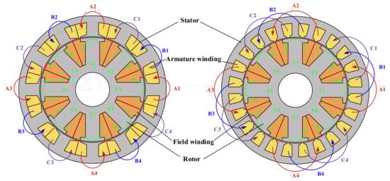
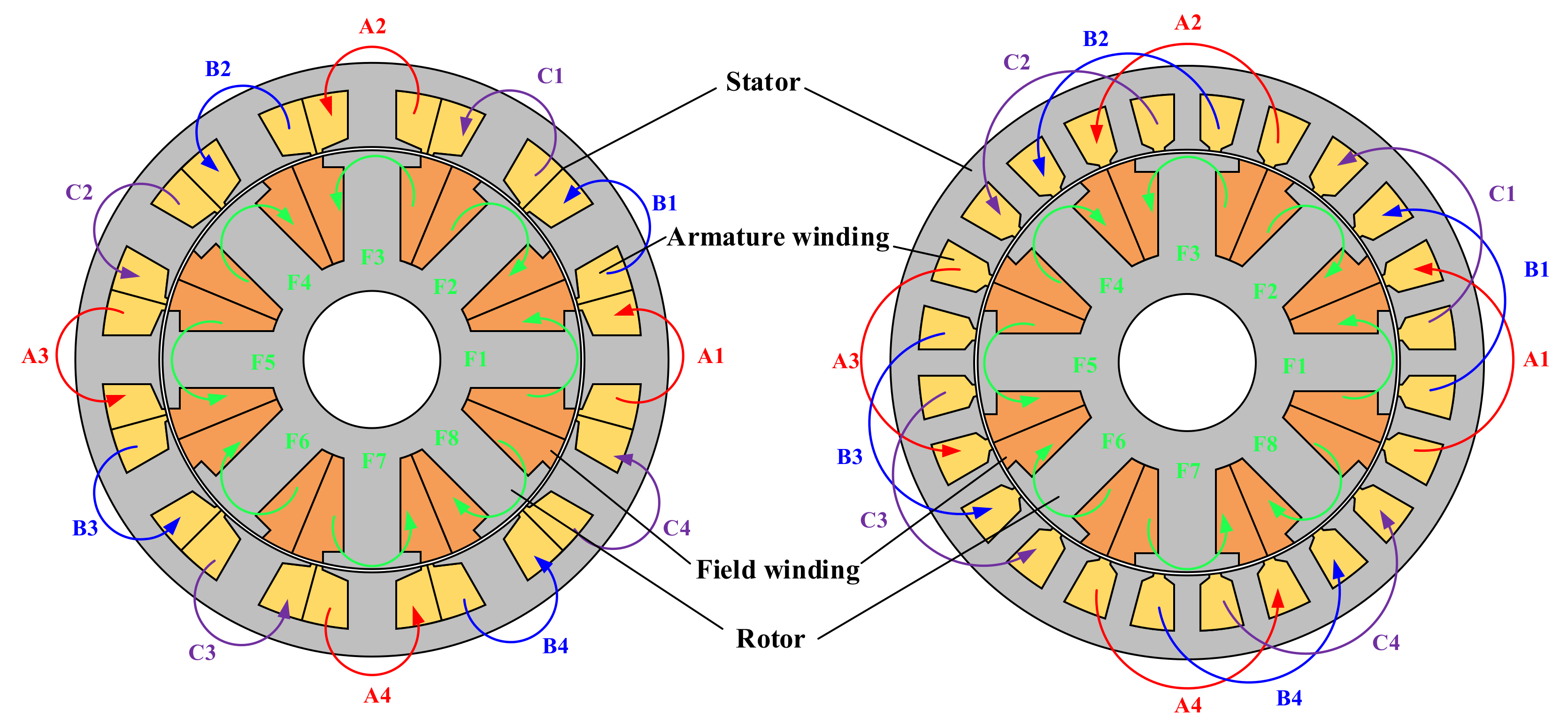
This paper will analyze the operation mechanism of the DC winding induced voltage in WRSM by using the air-gap field modulation principle [28,29,30]. The illustration of the analyzed WRSM can be found in Figure 1, and the innovations and contributions of this paper are as follows:
Figure 1.
Topology of the analyzed WRSM. (Left: 12-stator slot/4-rotor pole pair, concentrated armature winding. Right: 24-stator slot/4-rotor pole pair, distributed armature winding).
- (1)
- The analytical MMF-permeance model is established, based on which the spatial–temporal characteristics of the air-gap flux density are analyzed.
- (2)
- The operating mechanism of the DC winding induced voltage in WRSM is analyzed first, and the harmonic order of the DC winding induced voltage is deduced and compared with that predicted by FEA.
- (3)
- Winding configurations of concentrated winding and distributed winding are included in the analysis.
2. Magneto-Motive Force-Permeance Modeling for the DC Winding Induced Voltage in WRSM
2.1. Specifications of the Analyzed WRSMs
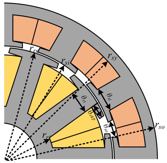
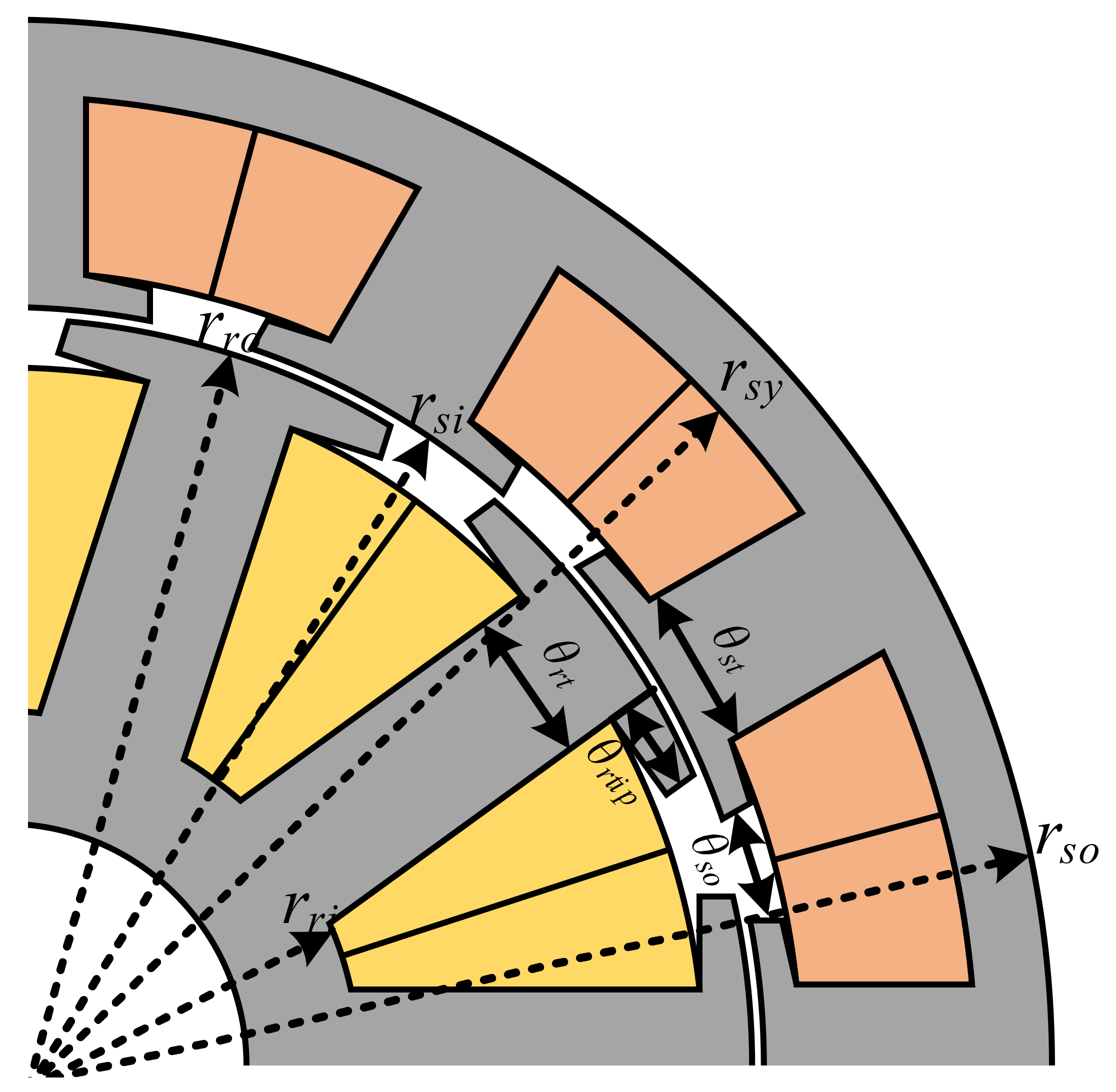
The specifications of the analyzed WRSMs are shown in Table 1, and the illustration of the parameters can be found in Figure 2. Different stator slots and rotor pole number combinations are included. All the parameters are optimized for maximum electromagnetic torque by using the genetic algorithm (GA). The optimized WRSMs all operate under the brushless alternating current (BLAC) mode, i.e., id = 0 control with fixed 60 W copper loss in both armature windings and DC winding. Both DC winding and armature winding also share the same packing factor kpf = 0.5.
Table 1.
Parameters of the Analyzed WRSMs.
Figure 2.
Linear illustrations of the WRSM parameters.
2.2. MMF-Permeance Modelling
This paper will use the MMF-permeance model to analyze the air-gap flux density of the WRSM. Based on the MMF-permeance model, both the spatial and temporal distribution characteristics of the air-gap flux density will be deduced.
Before establishing the MMF-permeance model of the WRSM, some assumptions should be made to simplify the analysis [31]:
- The steel permeability is infinite.
- Flux lines are perpendicular to the steel surface.
- The effect of finite stack length is negligible.
It should be noted that the MMF-permeance model is a 1-D analytical model for analyzing the flux density distribution characteristics. The main purpose is to analyze the spatial and temporal distribution characteristics of the air-gap flux density. Accurate prediction of the magnitude and phase angle of the flux density is not the main purpose of this paper. However, the MMF-permeance model can still shed light on figuring out the physical nature of DC winding induced voltage in WRSM. The impact of the saturation cannot be accounted in the MMF-permeance model, which will be analyzed by the FEA analysis.
2.2.1. Open-circuit condition
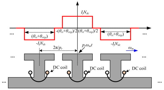
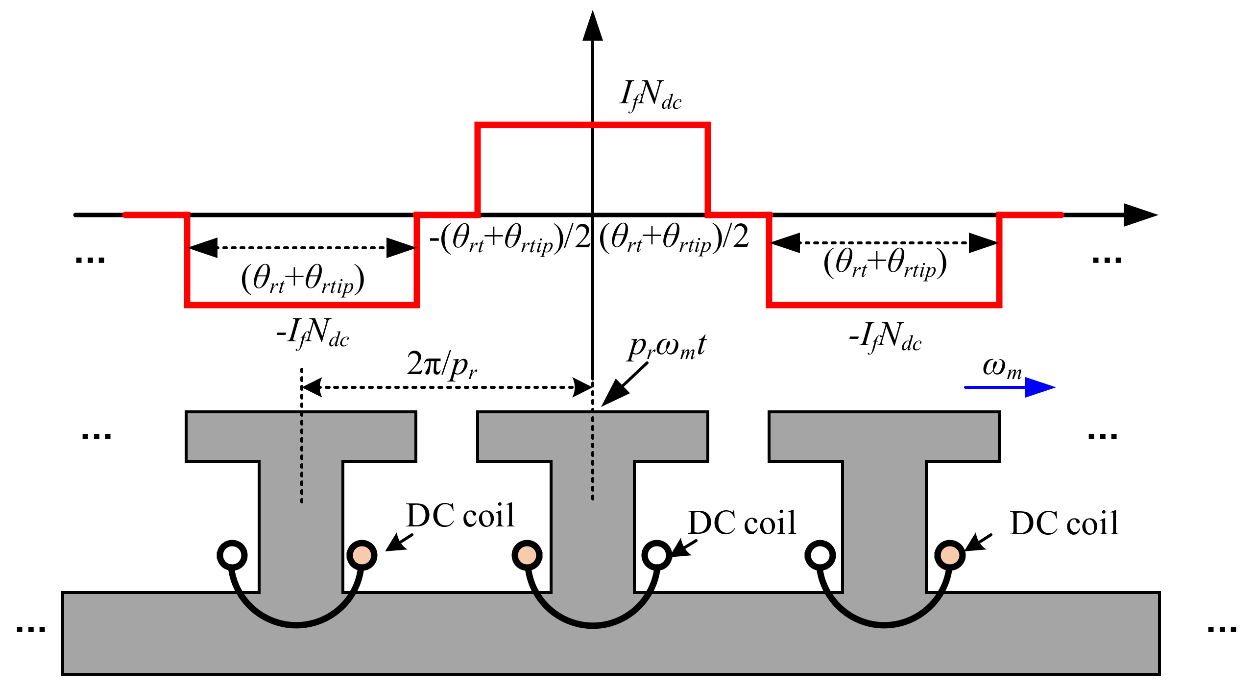
The DC winding MMF waveform of the WRSM can be found in Figure 3. By using the Fourier series transformation, the DC winding MMF can be expressed as
where Fdc(θm,t) is the MMF function of the DC winding, Wdc(θm,t) is the winding function of the DC winding, θm is the mechanical degree, ωm is the mechanical rotor angular speed and t is the time; If is the DC winding current.
Figure 3.
DC winding MMF waveform of the WRSM.
It can be observed from Equation (1) that DC winding MMF has only odd harmonics, which means the spatial order of the DC winding MMF function is the odd times of the rotor poles. The temporal order of the DC winding MMF function is 1, which is caused by the rotation.
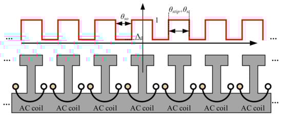
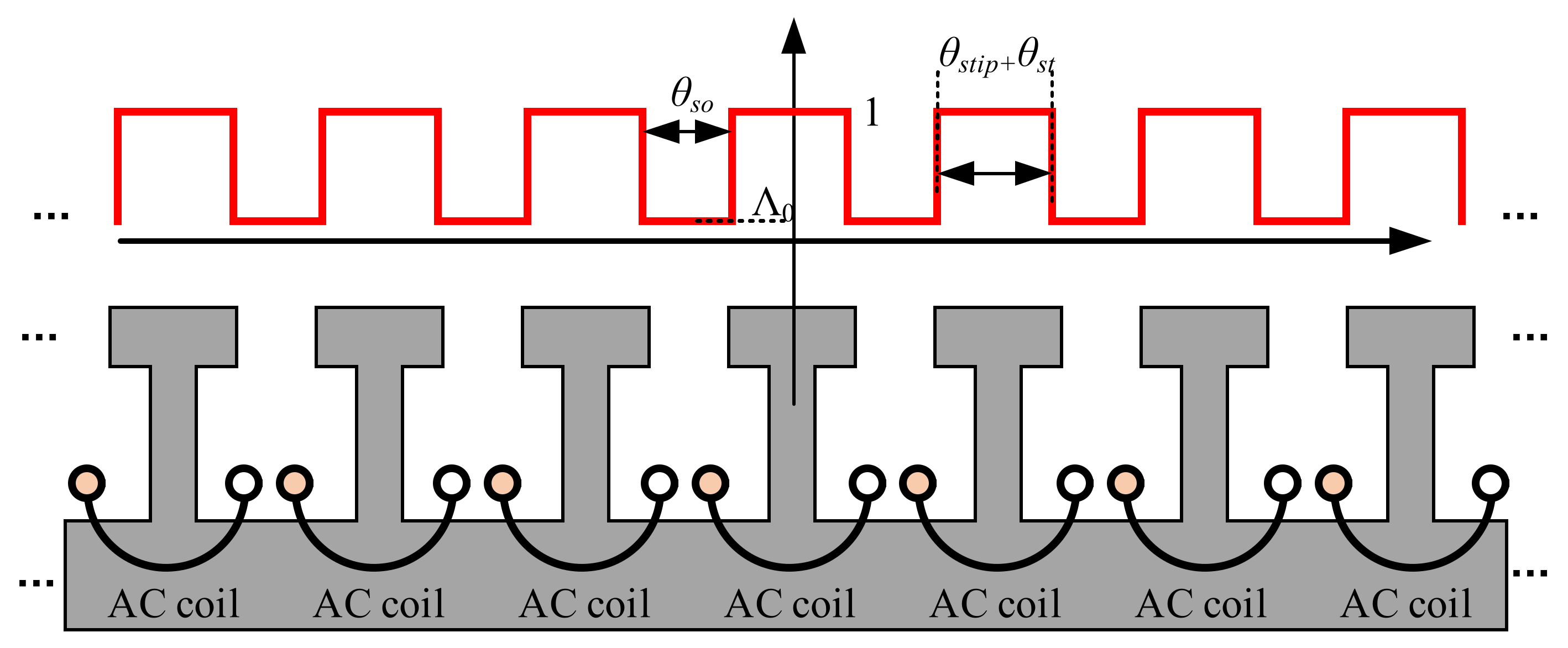
The stator relative permeance waveform of the WRSM can be found in Figure 4. By using the Fourier series transformation, the stator relative permeance function can be expressed as
where ans are Fourier transformation coefficient, Λs is the stator permeance function, Λ0 is the stator average permeance, θstip is the stator tooth-tip angle.
Figure 4.
Stator relative permeance waveform of the WRSM.
It can be observed from Equation (2) that the stator permeance function has a spatial order of Ns, 2Ns, 3Ns…. It should be noted that rotor permeance is not modeled in this paper since the DC winding MMF function contained the information on the rotor permeance.
According to [28], the open-circuit air-gap flux density Bgoc can be expressed as
where Bg is the air-gap flux density, μ0 is the vacuum permeability.
The open-circuit DC winding flux-linkage can be expressed as
where ψdcoc is the open-circuit DC winding flux-linkage.
It can be observed in Equation (4) that under the open-circuit condition, the DC winding MMF and the stator permeance function are critical factors for the open-circuit DC winding flux-linkage. Equation (4) is an integration equation with 0~2π integration range, therefore the flux density spatial order should satisfy the following equation to contribute to the open-circuit DC winding flux-linkage:
In addition, the open-circuit DC winding induced voltage cycle per electrical period Npeopen can be expressed as
For WRSM with a 12- or 24-stator slot and 4-rotor pole pair, Npeopen can be calculated based on Equation (6), and the results are listed in Table 2.
Table 2.
Predicted Npeopen for the Analyzed WRSMs.
2.2.2. Armature Reaction Condition
The effect of the armature reaction on DC winding induced voltage is related with the winding configuration [27]. In this paper, the analyzed 12/4 WRSM and 24/4 WRSM have double layer concentrated winding and single layer distributed winding, respectively.
The following analysis is based on the assumption that the armature windings are fed with three-phase symmetrical currents. Therefore, the three-phase currents can be expressed as,
where θi is the current angle, IA is the phase current amplitude.
The armature winding function can be expressed as
where WaA, WaB, and WaC are armature winding functions, WaA0 are the average values of the armature winding function, and anw are the Fourier transformations for the armature winding. WaA0 and anw for the analyzed 12/4 WRSM and 24/4 WRSM can be expressed as
It should be noted that Equation (8) can be easily extended for other winding configurations by calculating the WaA0 and anw for specific windings.
The armature winding MMF can be expressed as
where FA, FB, and FC are armature winding MMF for phase A, phase B and phase C.
The total armature winding MMF can be expressed as
Equation (11) can be rewritten as
The armature reaction air-gap flux density Bgar can be expressed as
where Λr is the rotor permeance function, it will be reflected by the DC winding function in the following. Since the armature MMF function contained the information on stator permeance, Equation (13) does not include the stator permeance function. The DC winding flux-linkage ψdcar caused by the armature reaction can be expressed as
And it can be rewritten as
It can be observed that in Equation (15) that the armature winding MMF (stator permeance is also included) and the DC winding function are the critical factors for the DC winding flux linkage, and the flux density spatial order should satisfy the following equation to contribute to the open-circuit DC winding flux-linkage:
where (2i − 1)pr is the spatial order introduced by the DC winding function, and npr is the spatial order introduced by armature winding MMF. By solving Equation (16), only when n = 6k − 1 or 6k + 1, k = 1,2,3… can the corresponding flux density contribute to the DC winding flux-linkage.
The DC winding induced voltage per cycle under armature reaction condition Npear can be expressed as
By using Equation (17), Npear can be predicted, which is listed in Table 3.
Table 3.
Predicted Npear for the Analyzed WRSMs.
2.2.3. On-Load Condition
According to superposition principle, the on-load air-gap flux density is the sum of the open-circuit condition and armature reaction condition, and so is the DC winding flux linkage. Therefore, the on-load DC winding flux linkage is the sum of open-circuit flux linkage and armature reaction flux linkage. The on-load DC winding induced voltage cycle per electrical period Npeol can be expressed as the least common multiple of Npeopen and Npear. For the analyzed WRSM, the prediction results of Npeol are listed in Table 4,
Table 4.
Predicted Npeol for the Analyzed WRSMs.
3. FEA Verification
In order to verify the correctness of the operating mechanism analysis on DC winding induced voltage in WRSM, both 12/4 WRSM and 24/4 WRSM were analyzed by FEA. Both open-circuit and on-load performance, including cogging torque, on-load torque, DC winding flux linkage and DC winding induced voltage are included in the analysis. It should be noted that analysis results between electrical steel material with nonlinear B–H curve characteristic and constant relative permeability characteristic are also compared to analyze the influence of saturation on the DC winding induced voltage.
3.1. Open-Circuit Condition
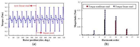
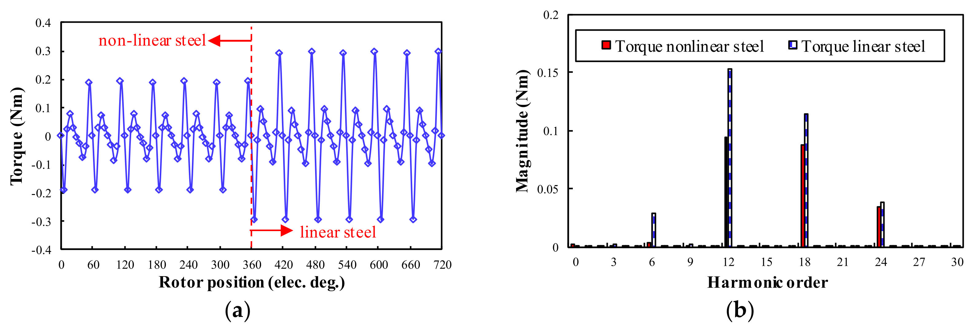
The cogging torque waveform and spectra for 12/4 WRSM and 24/4 WRSM are shown in Figure 5 and Figure 6. The cogging torque of both 12/4 WRSM and 24/4 WRSM suffers from 6kth (k = 1,2,3…) harmonics. It can be observed from the spectra that the saturation will influence the magnitude of cogging torque harmonics. However, the steel saturation has a different effect on 12/4 and 24/4 WRSM.
Figure 5.
Cogging torque waveforms and spectra for 12/4 WRSM: (a) Waveforms; (b) Spectra.
Figure 6.
Cogging torque waveforms and Spectra for 24/4 WRSM, (a) Waveforms; (b) Spectra.
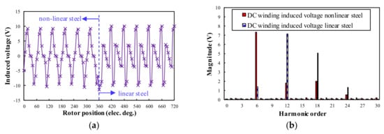
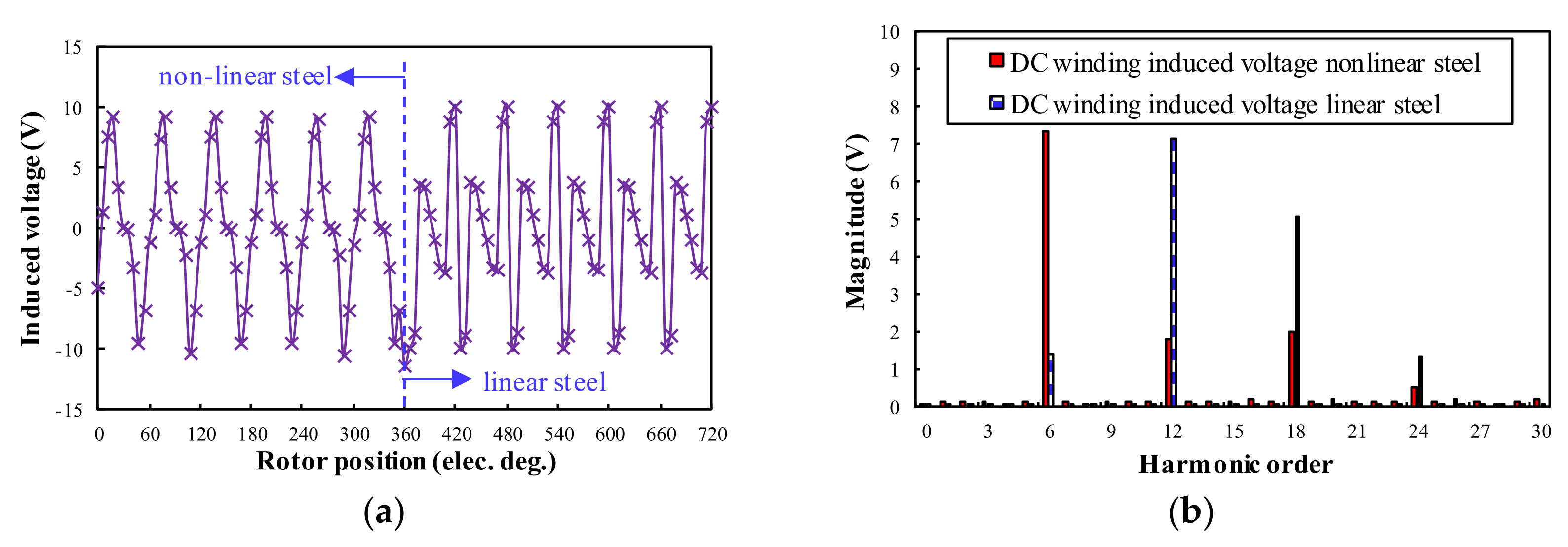
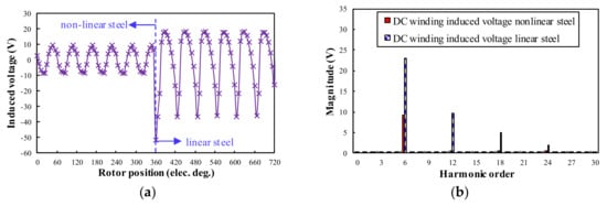
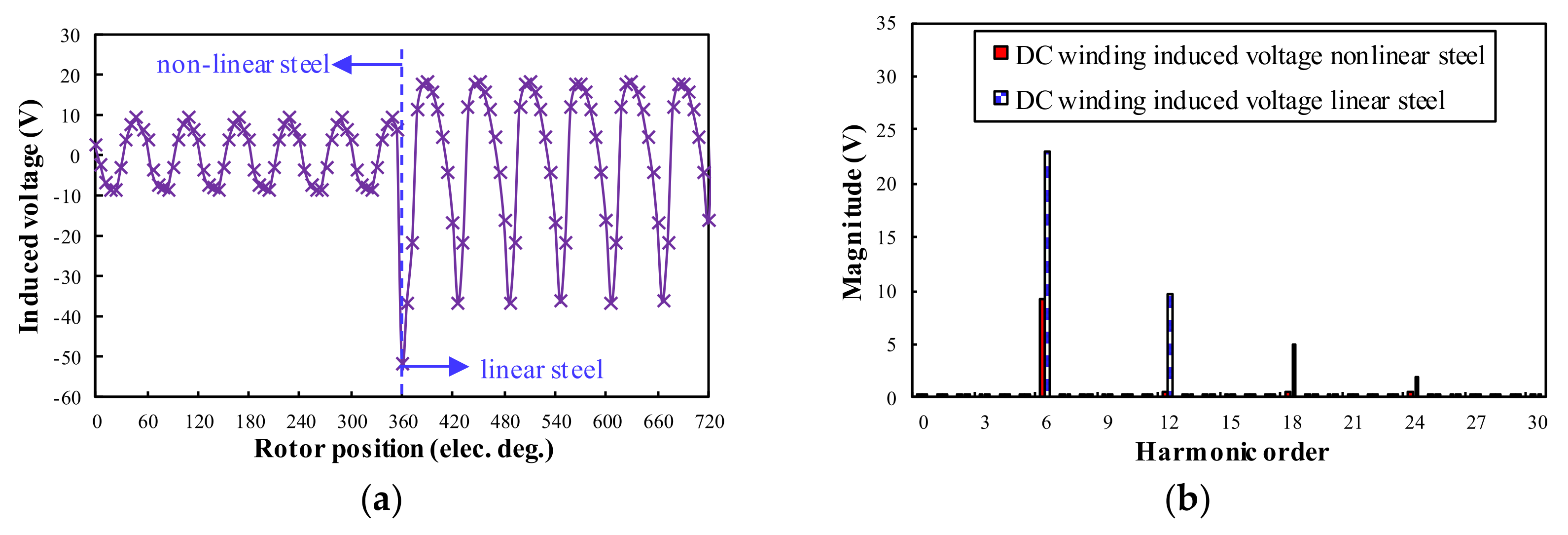
As for the open-circuit DC winding induced voltage, it can be seen in Figure 7 and Figure 8 that both 12/4 and 24/4 WRSM have Npeopen = 6, which is the same as the prediction result in Table 2. The influence of steel saturation will not influence the harmonic order of the open-circuit DC winding induced voltage. However, the steel saturation will influence the magnitude of the open-circuit DC winding induced voltage. This is evident for the 24/4 WRSM, which has higher amplitude open-circuit DC winding induced voltage. As for the 12/4 WRSM, the saturation will result in a higher magnitude of the 12th harmonic DC winding induced voltage.
Figure 7.
Open-circuit DC winding induced voltage waveforms and spectra for 12/4 WRSM, (a) Waveforms; (b) Spectra.
Figure 8.
Open-circuit DC winding induced voltage waveforms and spectra for 24/4 WRSM, (a) Waveforms; (b) Spectra.
3.2. On-Load Condition
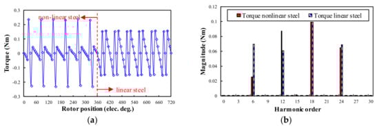
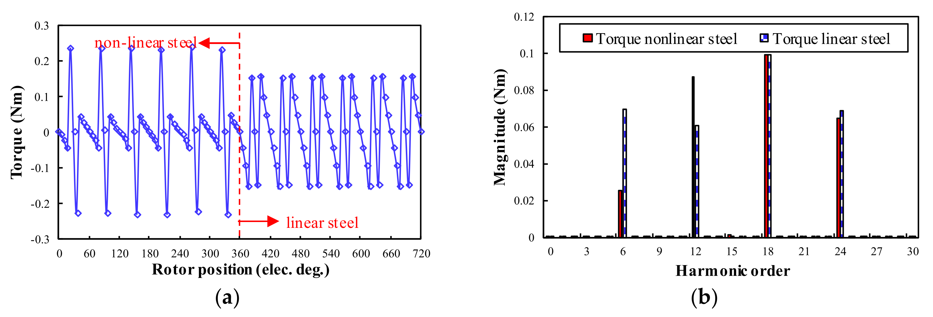
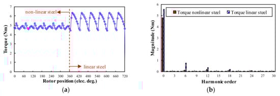
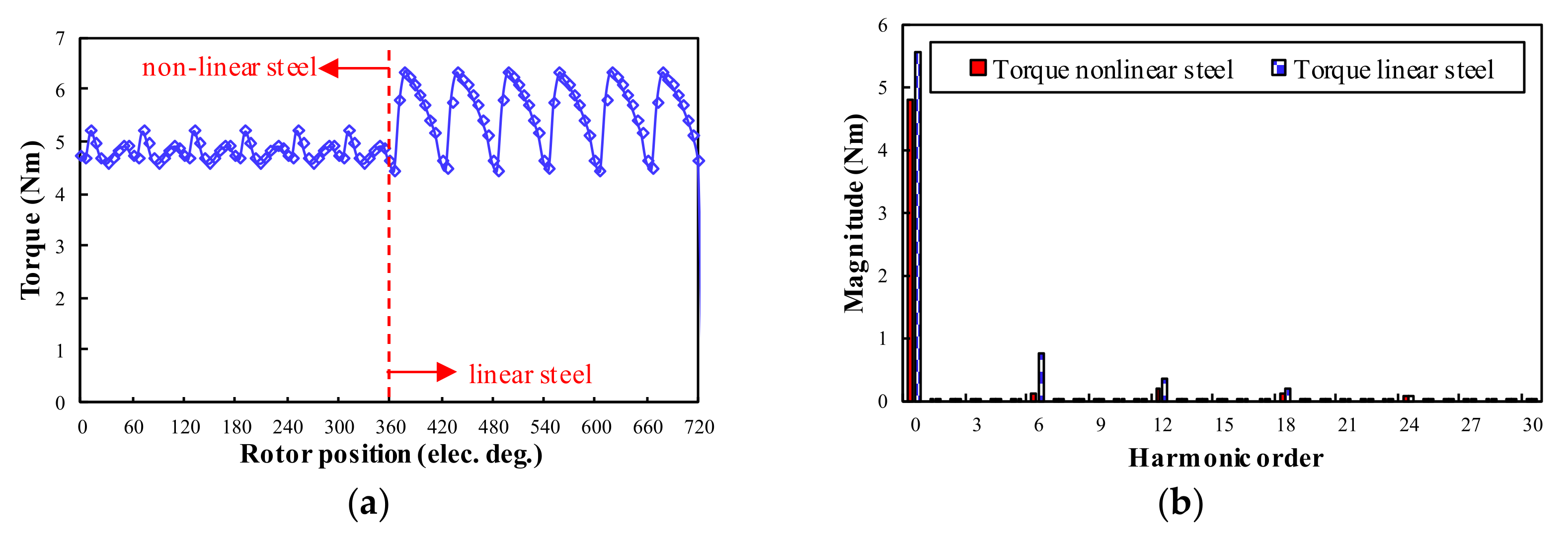
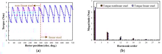
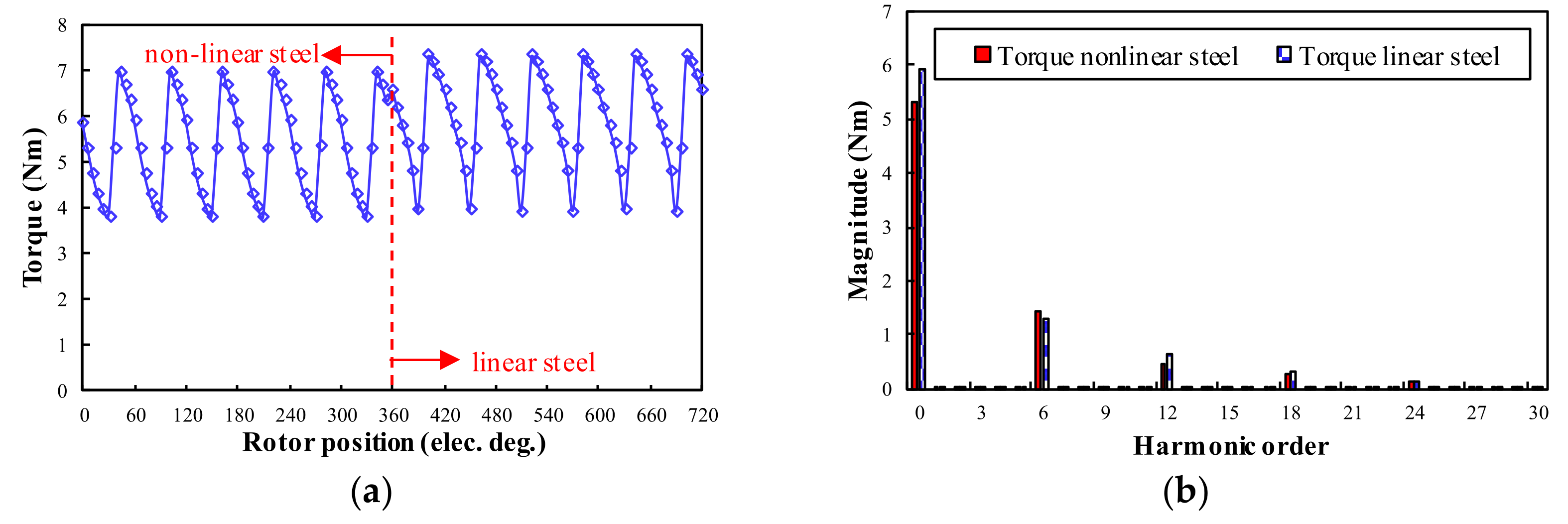
The on-load torque waveforms and spectra for 12/4 WRSM and 24/4 WRSM can be seen in Figure 9 and Figure 10, respectively. The on-load torque suffers from 6kth (k = 1,2,3…) harmonics. The average on-load torque under the linear steel condition is much higher than that under the non-linear steel condition.
Figure 9.
On-load torque waveforms and spectra for 12/4 WRSM: (a) Waveforms; (b) Spectra.
Figure 10.
On-load torque waveforms and spectra for 24/4 WRSM: (a) Waveforms; (b) Spectra.
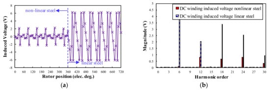
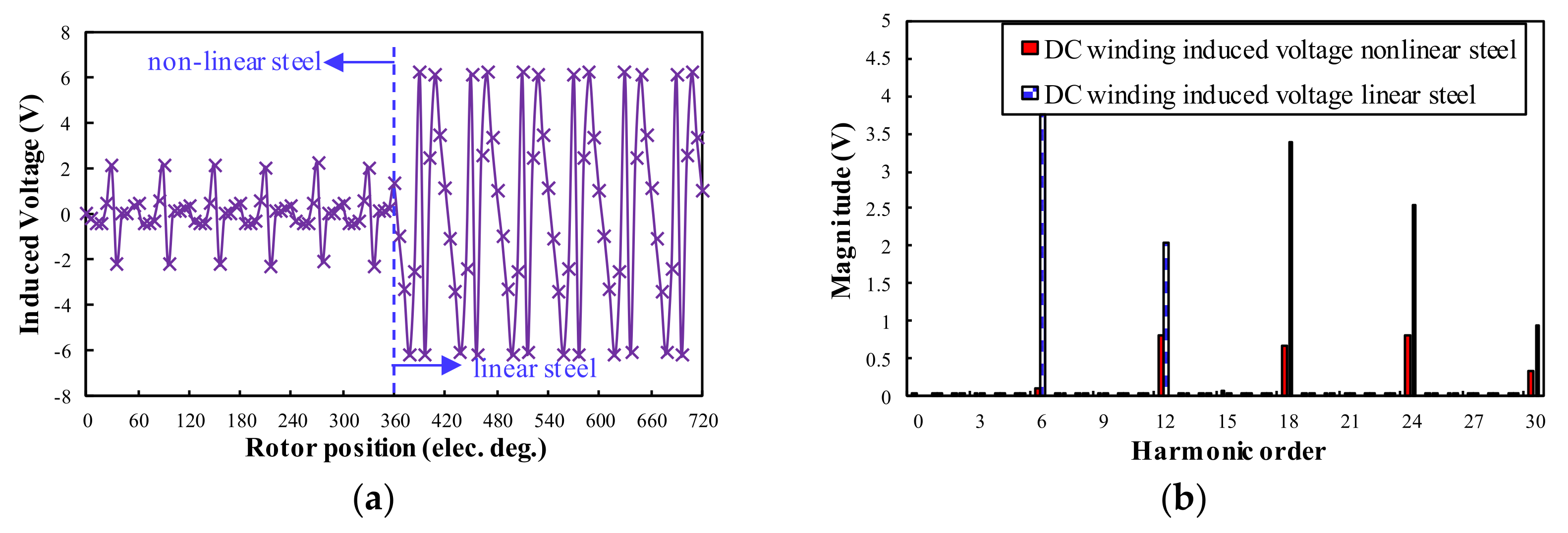
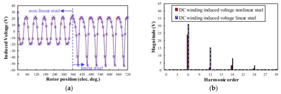
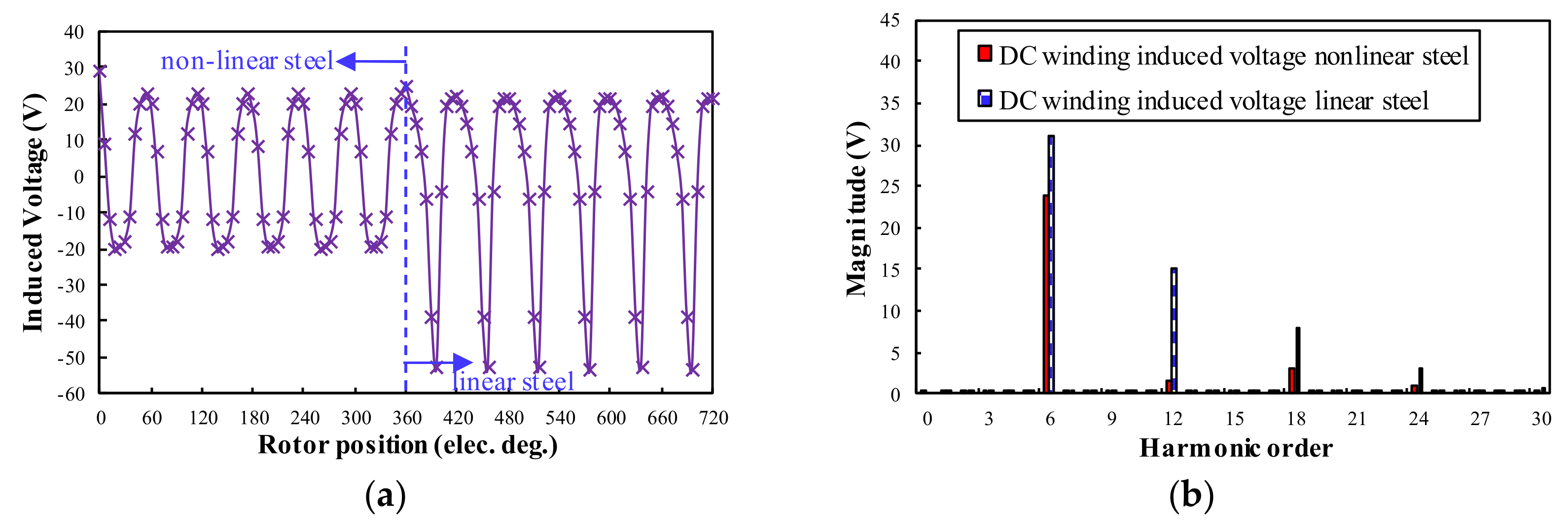
As shown in Figure 11 and Figure 12, the on-load DC winding induced voltage in both 12/4 and 24/4 WRSM has Npeol = 6, which is the same as the prediction result in Table 4. As for the influence of the steel saturation, the on-load DC winding induced voltage has a much higher amplitude for both WRSM machines. However, the steel saturation will not influence the harmonic order of the DC winding induced voltage. The 24/4 WRSM with distributed armature winding has a higher amplitude of DC winding induced voltage than that of 12/4 WRSM with the concentrated armature winding.
Figure 11.
On-load DC winding induced voltage waveforms and spectra for 12/4 WRSM: (a) Waveforms; (b) Spectra.
Figure 12.
On-load DC winding induced voltage waveforms and spectra for 24/4 WRSM: (a) Waveforms; (b) Spectra.
Finally, the FEA prediction results of both Npeopen and Npeol are listed in Table 5, which agree well with the analysis result of the MMF-permeance model in Table 2 and Table 4.
Table 5.
FEA Predicted DC Winding Induced Voltage Cycles per Electrical Period.
4. Conclusions
This paper analyzes the operating mechanism of the DC winding induced voltage in both 12/4 WRSM and 24/4 WRSM with concentrated armature winding and distributed armature winding, respectively. By using the air-gap field modulation principle, the MMF-permeance model of the WRSM is established. DC winding MMF, armature reaction MMF and permeance function are modeled analytically in the MMF-permeance model. Then, based on the spatial–temporal characteristics of the effective air-gap flux density for the DC winding, the induced voltage cycle per electrical period Npeopen, Npear and Npeal are deduced analytically. The deduced results are verified by the FEA with linear steel and non-linear steel, which shows that the analytical prediction results agree well with the FEA analysis results. The analytical model in this paper can give a straightforward insight into the physical nature of the DC winding-induced voltage in WRSM. However, the analytical model cannot predict the magnitude and phase angle of the DC winding induced voltage, since the main purpose of this paper is to analyze the operating mechanism of the DC winding-induced voltage in WRSM. It is different from that in the wound field switched flux machine, which was analyzed in [20,27]. Based on the analysis presented in this paper, reduction methods investigation of the DC winding induced voltage for WRSM is the next stage of work for this paper.
Author Contributions
Conceptualization, methodology, software and writing—original draft preparation, W.Z.; validation, Y.F.; formal analysis, Z.W.; supervision, Y.F., Z.Q.Z., Z.W., W.H. and M.C. All authors have read and agreed to the published version of the manuscript.
Funding
This research was supported in part by the Natural Science Foundation of Jiangsu Province under Project BK20210242, and in part by the National Natural Science Foundation of China under Project 52107037.
Data Availability Statement
Not applicable.
Conflicts of Interest
The authors declare no conflict of interest.
References
- Raghuraman, B.; Nategh, S.; Sidiropoulos, N.; Petersson, L.; Boglietti, A. Sustainability aspects of electrical machines for E-mobility applications part I: A design with reduced rare-earth elements. In Proceedings of the 47th Annual Conference of the IEEE Industrial Electronics Society, Toronto, ON, Canada, 13–16 October 2021. [Google Scholar]
- Boldea, I.; Tutelea, L.N.; Parsa, L.; Dorrell, D. Automotive Electric Propulsion Systems With Reduced or No Permanent Magnets: An Overview. IEEE Trans. Ind. Electron. 2014, 61, 5696–5711. [Google Scholar] [CrossRef] [Scilit]
- Widmer, J.D.; Martin, R.; Kimiabeigi, M. Electric vehicle traction motors without rare earth magnets. Sustain. Mater. Technol. 2015, 3, 7–13. [Google Scholar] [CrossRef] [Scilit]
- Lipo, T.A.; Du, Z.S. Synchronous motor drives-a forgotten option. In Proceedings of the 2015 Intl Aegean Conference on Electrical Machines & Power Electronics, 2015 Intl Conference on Optimization of Electrical & Electronic Equipment & 2015 Intl Symposium on Advanced Electromechanical Motion Systems, Side, Turkey, 2–4 September 2015; pp. 1–5. [Google Scholar]
- The BMW iX3 between Design and Art. Available online: https://www.bmw.com/en/design/aerodynamic-rims-BMW-iX3-design-meets-art.html (accessed on 9 October 2021).
- Specifications of the Renault ZOE Motor. Available online: https://www.renaultgroup.com/en/news-on-air/news/the-renault-zoe-motor-energy-efficiency-and-power/ (accessed on 9 October 2021).
- MAHLE Develops Highly Efficient Magnet-Free Electric Motor. Available online: https://www.mahle.com/en/news-and-press/press-releases/mahle-develops-highly-efficient-magnet-free-electric-motor--82368 (accessed on 9 October 2021).
- Nie, Y.; Brown, I.P.; Ludois, D.C. Deadbeat-Direct Torque and Flux Control for Wound Field Synchronous Machines. IEEE Trans. Ind. Electron. 2017, 65, 2069–2079. [Google Scholar] [CrossRef] [Scilit]
- Tang, J.; Liu, Y.; Lundberg, S. Estimation Algorithm for Current and Temperature of Field Winding in Electrically Excited Synchronous Machines With High-Frequency Brushless Exciters. IEEE Trans. Power Electron. 2020, 36, 3512–3523. [Google Scholar] [CrossRef] [Scilit]
- Chu, W.Q.; Zhu, Z.Q.; Chen, J.T. Simplified Analytical Optimization and Comparison of Torque Densities Between Electrically Excited and Permanent-Magnet Machines. IEEE Trans. Ind. Electron. 2013, 61, 5000–5011. [Google Scholar] [CrossRef] [Scilit]
- Ma, Y.; Wang, J.; Xiao, Y.; Zhou, L.; Zhu, Z.Q. Two-Level Surrogate-Assisted Transient Parameters Design Optimization of a Wound-Field Synchronous Machine. IEEE Trans. Energy Convers. 2021, 37, 737–747. [Google Scholar] [CrossRef] [Scilit]
- Chai, W.; Kwon, B.-I. Design of an asymmetric rotor pole for wound field synchronous machines. CES Trans. Electr. Mach. Syst. 2021, 5, 321–327. [Google Scholar] [CrossRef] [Scilit]
- Nuzzo, S.; Galea, M.; Bolognesi, P.; Vakil, G.; Fallows, D.; Gerada, C.; Brown, N.L. A Methodology to Remove Stator Skew in Small–Medium Size Synchronous Generators via Innovative Damper Cage Designs. IEEE Trans. Ind. Electron. 2018, 66, 4296–4307. [Google Scholar] [CrossRef] [Scilit]
- Quadri, Q.H.; Nuzzo, S.; Rashed, M.; Gerada, C.; Galea, M. Modeling of Classical Synchronous Generators Using Size-Efficient Lookup Tables With Skewing Effect. IEEE Access 2019, 7, 174551–174561. [Google Scholar] [CrossRef] [Scilit]
- Wang, Y.; Nuzzo, S.; Gerada, C.; Zhang, H.; Zhao, W.; Galea, M. Integrated Damper Cage for THD Improvements of Variable Speed Salient-Pole Synchronous Generators for the More Electric Aircraft. IEEE Trans. Transp. Electrif. 2021, 8, 3618–3629. [Google Scholar] [CrossRef] [Scilit]
- Wang, Y.; Nuzzo, S.; Zhang, H.; Zhao, W.; Gerada, C.; Galea, M. Challenges and Opportunities for Wound Field Synchronous Generators in Future More Electric Aircraft. IEEE Trans. Transp. Electrif. 2020, 6, 1466–1477. [Google Scholar] [CrossRef] [Scilit]
- Fu, X.; Qi, Q.; Tan, L. Design and Analysis of Brushless Wound Field Synchronous Machine With Electro-Magnetic Coupling Resonators. IEEE Access 2019, 7, 173636–173645. [Google Scholar] [CrossRef] [Scilit]
- Ludois, D.C.; Reed, J.K.; Hanson, K. Capacitive Power Transfer for Rotor Field Current in Synchronous Machines. IEEE Trans. Power Electron. 2012, 27, 4638–4645. [Google Scholar] [CrossRef] [Scilit]
- Fallows, D.; Nuzzo, S.; Galea, M. Exciterless Wound-Field Medium-Power Synchronous Machines: Their History and Future. IEEE Ind. Electron. Mag. 2021. [Google Scholar] [CrossRef] [Scilit]
- Wu, Z.Z.; Zhu, Z.Q.; Wang, C.; Mipo, J.C.; Personnaz, S.; Farah, P. Reduction of Open-Circuit DC-Winding-Induced Voltage in Wound Field Switched Flux Machines by Skewing. IEEE Trans. Ind. Electron. 2018, 66, 1715–1726. [Google Scholar] [CrossRef] [Scilit]
- Zulu, A.; Mecrow, B.C.; Armstrong, M. A Wound-Field Three-Phase Flux-Switching Synchronous Motor With All Excitation Sources on the Stator. IEEE Trans. Ind. Appl. 2010, 46, 2363–2371. [Google Scholar] [CrossRef] [Scilit]
- Wu, Z.; Zhu, Z.-Q.; Wang, C.; Mipo, J.-C.; Personnaz, S.; Farah, P. Analysis and Reduction of On-Load DC Winding Induced Voltage in Wound Field Switched Flux Machines. IEEE Trans. Ind. Electron. 2019, 67, 2655–2666. [Google Scholar] [CrossRef] [Scilit]
- Wu, Z.; Zhu, Z.Q.; Hua, W.; Akehurst, S.; Zhu, X.; Zhang, W.; Hu, J.; Li, H.; Zhu, J. Analysis and Suppression of Induced Voltage Pulsation in DC Winding of Five-Phase Wound-Field Switched Flux Machines. IEEE Trans. Energy Convers. 2019, 34, 1890–1905. [Google Scholar] [CrossRef] [Scilit]
- Yu, L.; Zhang, M.; Zhang, Z.; Jiang, B. Reduction of Field-Winding-Induced Voltage in a Doubly Salient Brushless DC Generator With Stator-Damper Winding. IEEE Trans. Ind. Electron. 2021, 69, 7767–7775. [Google Scholar] [CrossRef] [Scilit]
- Sun, X.; Zhu, Z.Q. Investigation of DC Winding Induced Voltage in Hybrid-Excited Switched-Flux Permanent Magnet Machine. IEEE Trans. Ind. Appl. 2020, 56, 3594–3603. [Google Scholar] [CrossRef] [Scilit]
- Sun, X.; Zhu, Z.Q.; Wei, F.R. Voltage Pulsation Induced in DC Field Winding of Different Hybrid Excitation Switched Flux Machines. IEEE Trans. Ind. Appl. 2021, 57, 4815–4830. [Google Scholar] [CrossRef] [Scilit]
- Zhang, W.; Hua, W.; Wu, Z.; Zhao, G.; Wang, Y.; Xia, W. Analysis of DC Winding Induced Voltage in Wound-Field Flux-Switching Machine With Air-Gap Field Modulation Principle. IEEE Trans. Ind. Electron. 2021, 69, 2300–2311. [Google Scholar] [CrossRef] [Scilit]
- Cheng, M.; Han, P.; Hua, W. General Airgap Field Modulation Theory for Electrical Machines. IEEE Trans. Ind. Electron. 2017, 64, 6063–6074. [Google Scholar] [CrossRef] [Scilit]
- Wu, Z.Z.; Zhu, Z.Q. Analysis of Air-Gap Field Modulation and Magnetic Gearing Effects in Switched Flux Permanent Magnet Machines. IEEE Trans. Magn. 2015, 51, 8105012. [Google Scholar] [CrossRef] [Scilit]
- Li, D.; Qu, R.; Li, J.; Xiao, L.; Wu, L.; Xu, W. Analysis of Torque Capability and Quality in Vernier Permanent-Magnet Machines. IEEE Trans. Ind. Appl. 2015, 52, 125–135. [Google Scholar] [CrossRef] [Scilit]
- Zhu, X.; Hua, W.; Wu, Z.; Huang, W.; Zhang, H.; Cheng, M. Analytical Approach for Cogging Torque Reduction in Flux-Switching Permanent Magnet Machines Based on Magnetomotive Force-Permeance Model. IEEE Trans. Ind. Electron. 2017, 65, 1965–1979. [Google Scholar] [CrossRef] [Scilit]

Publisher’s Note: MDPI stays neutral with regard to jurisdictional claims in published maps and institutional affiliations. |
© 2022 by the authors. Licensee MDPI, Basel, Switzerland. This article is an open access article distributed under the terms and conditions of the Creative Commons Attribution (CC BY) license (https://creativecommons.org/licenses/by/4.0/).