Abstract
In the commercialization process of wireless electric vehicle charging (WEVC), it is essential to ensure the interoperability between diverse WEVC systems due to the wide application of various coil configurations and compensation topologies. This paper proposes a novel electrical interoperability evaluation method based on impedance indices and corresponding feasible space in the complex plane. Firstly, the electromagnetic description of the coil system is introduced to reveal the energy flow process of WEVC system. Further, two key impedance indices and their feasible space are derived and verified. Interoperability evaluation results show that the reference devices in Chinese WEVC standard GB/T 38775.6 and GB/T 38775.7 are able to achieve the requirements of power capability. Moreover, it is necessary to reduce the duty cycle of rectifier when the battery voltage rises so as to narrow down the variation of load resistance and avoid dangerous working conditions. The proposed method can effectively evaluate the electrical interoperability of WEVC systems from different manufacturers under different power or distance levels before conducting experiments.
1. Introduction
Wireless electric vehicle charging (WEVC) is stepping onto the stage of commercialization. However, in order to promote the progress of WEVC technology, it is necessary to maintain the diversity of product designs. Currently, there are many well-established coil configurations and compensation topologies for WEVC system [1].
Interoperability of WEVC means that ground assemblies (GA) and vehicle assemblies (VA) produced by different WEVC manufacturers can transmit power and meet the performance and functional requirements. It also implies that systems under different power and ground clearance levels should operate with each other in accordance with certain rules. Table 1 and Table 2 show the definition and interoperability requirements of power levels and ground clearance levels in exposure drafts of Chinese GB/T standard [2,3,4,5].

Table 1.
Interoperability requirements for different power levels.

Table 2.
Interoperability requirements for different ground clearance levels.
The magnetic coupling system (i.e., coil system) and compensation circuit are two key components of WEVC systems. As a result, magnetic interoperability and electrical interoperability are proposed in international standards such as SAE J2954 [6]. This paper focuses on electrical interoperability, which means that the compensation networks of GA and VA should work well with each other and meet the power and efficiency requirement.
Figure 1 summarizes the interoperability for different compensation topologies in literatures [7,8,9,10,11,12,13]. As a topology with remarkable performance, the interoperability between LCC topology and other topologies receives extensive attention. Ali Ramezani et al. analyzed the LCC-S topology in the time domain and pointed out that the topology has the characteristics of output constant voltage and can realize zero voltage switching [10]. Ruikun Mai et al. analyzed the S-LCC topology and proved that it can realize weak communication control and input zero phase angle [11]. In addition, interoperation experiments on LCC compensation and Parallel compensation are carried out and the results show that all combinations of LCC and Parallel can achieve power and efficiency requirements [12,13]. However, these studies apply different evaluation methods and criteria, and even different circuit structures, which makes it difficult to get a general conclusion.
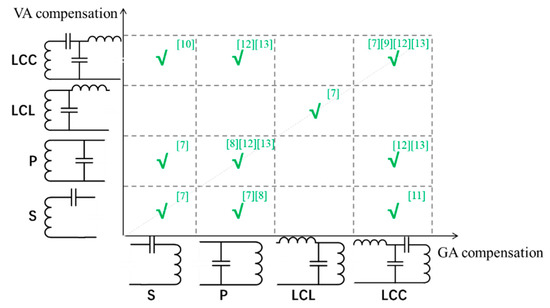
Figure 1.
Interoperability for different GA and VA compensation.
To describe the electrical interoperability, the VA side impedance ZVA and the GA side impedance ZGA are defined in SAE J2954, as presented in Figure 2. Several recommended parameters for GA side impedance are derived based on the performance of reference devices. The analysis in the SAE standard is of great value for the evaluation and optimization of interoperability. Nevertheless, it cannot reflect the influence of circuit constraints (such as coil current, DC input voltage) on electrical interoperability.

Figure 2.
Definition of ZGA and ZVA in SAE J2954.
This paper proposes a novel electrical interoperability evaluation method based on impedance analysis. Current and voltage limits of key components are transformed into constraints of circuit impedance parameters, and consequently, the power capability of the system can be evaluated by inclusion relationship between the feasible impedance space and operating impedance points. The method is based on a general circuit model for WEVC system so it can be applied to various circuit topologies with a very small amount of calculation.
The paper is organized as follows. Section 2 introduces the electromagnetic description of a coil system and derives the power equation of WEVC system. In Section 3, key impedance indices and their feasible space are proposed to describe electrical interoperability. The method is applied and validated based on a set of interoperability experiments in Section 4. Finally, some conclusions and discussions are summarized in Section 5.
2. Electromagnetic Description of Coil System
This section discusses the essence of a coil system from the perspective of electromagnetism. No matter what coil configuration and compensation topology are used in a wireless charging circuit, the coil system can be regarded as a storage and transmission system of electromagnetic energy, as shown in Figure 3. This is a two-port system, and energy can flow into or out of the system via the two ports. When neglecting the coil loss, the power flow of the system at arbitrary time is described as below.
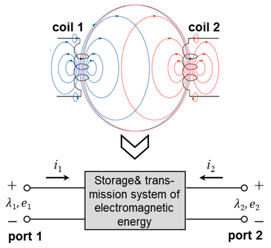
Figure 3.
The essence of coil system from the perspective of electromagnetism.
P1 and P2 mean the power flow at port 1 and port 2. If the power flows into the system from port 1, P1 is positive, otherwise it is negative. The same rule applies to port 2. Wmag refers to the magnetic energy stored in the system, and dWmag/dt shows the change rate of magnetic energy.
Regarding the coil currents i1, i2 as state variables, the state equations of the system can be derived according to the electromagnetism.
Firstly, flux linkage equations are
where λ1, λ2 are the magnetic fluxes of coil 1 and coil 2, L1, L2 are self-inductances, and M is mutual inductance between the two coils.
Secondly, electricity and magnetism are connected by Faraday’s law:
where e1, e2 are the voltages at port 1 and port 2.
The last state equation is a variant of Equation (1):
Combining Equations (2)–(4), we can obtain the following expression:
Integrating the above equation, we can get magnetic energy stored in the coil system:
In Wmag, and are the energy of the self-induced flux in coil 1 and coil 2, respectively. These two parts of energy only flow back and forth on one side, but not to the other side. Mi1i2 is the energy of a mutual induced flux, which can flow from one side to the other, as shown in Figure 4. In a current cycle, when port 1 inputs energy to the coil system, port 2 outputs energy from the coil system (or vice versa).
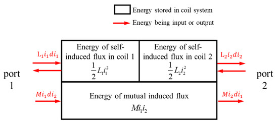
Figure 4.
Composition of energy stored in coil system and energy flow.
Suppose that i1 and i2 are alternating currents with a phase difference φ12:
where I1, I2 are the effective values of i1, i2 and ω is the angular frequency. In one current cycle, the energy transferred from port 1 to port 2 is:
Therefore, the transmission power of any coil system can be expressed as:
According to Equation (9), the determinants of transmission power are summarized as follows. (a) Coil current angular frequency ω, higher frequency can help achieve higher power density. (b) Mutual inductance M, which reflects the magnetic coupling characteristics between the coils. (c) Effective values of coil currents I1, I2, which reflect the power capacity of coils, compensation network and other power electronics on both sides. (d) Phase difference φ12 of coil currents, which reflects the degree of mutual induced energy transformed into effective transmission energy. When φ12 = ±90°, all the energy input from one port can output into the other port (the direction of energy flow depends on the sign of φ12). Otherwise, there will be some energy backflow, which means that the power transmission capacity declines, as shown in Figure 5. Compared with an ideal situation φ12 = 90°, the power capacity is reduced by 13%, 29%, in the case of φ12 = 60°, 45°, and 30°, respectively.
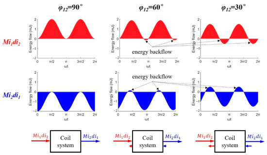
Figure 5.
Energy flow at different φ12 in a current cycle (M = 10 μH, I1 = 10 A, I2 = 10 A).
3. Evaluation Indices of Electrical Interoperability
3.1. Definition of Key Impedance
With the help of circuit theory, the interoperability of WEVC system can be further evaluated. Figure 6 sketches a universal WEVC circuit model, including voltage source, coil system, compensation networks, and battery load. LP, LS, and M are self-inductance of GA coil, self-inductance of VA coil, and their mutual inductance. The model adopts the T-type equivalent circuit of mutual inductance to realize a decoupled connection of GA and VA circuits. In addition to the design of coils on both sides, coil inductance parameters {LP, LS, M} are also affected by the relative position between the coils. As a result, compensation networks are introduced into both sides of charging system so as to compensate the reactive power generated by coil system.
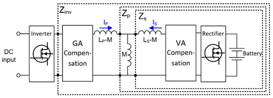
Figure 6.
Circuit model and impedance definition of WEVC system.
Therefore, impedance is the key to analysing the power flow in WEVC circuit, and it is also an important indicator for judging the interoperability between GA and VA. A GA-VA pair which achieves interoperability means that the circuit impedance is controlled within a reasonable range under all possible charging conditions and possible coil inductance parameters {LP, LS, M}, so that power electronics will not exceed their safe operating area.
As indicated in Figure 6, ZS, ZP, and Zinv are the three key impedances. ZS includes the load, VA compensation network, and decoupled VA coil (i.e., LS-M). On the basis of ZS range, ZP includes mutual inductance branch additionally. Zinv is the input impedance of the inverter, including GA compensation network, coil system and the whole VA circuit.
3.2. Interoperability Evaluation Index I: Zinv
The role of Zinv is to convert a safe operating area of the inverter into a safe impedance area of the circuit. Assume that the maximum voltage and current of the inverter are Uinv_max and Iinv_max, respectively.
According to Ohm’s law of AC circuit,
The input power can be expressed as
where |Zinv| and φ(Zinv) are the amplitude and phase of the impedance Zinv.
From Equations (10) and (12), the amplitude constraints of Zinv are derived:
In addition, in order to ensure the soft switching operation of the inverter, the phase of Uinv is generally required to be ahead of Iinv, which is essentially a constraint of φ(Zinv).
With the help of the Zinv amplitude constraints (13) and Zinv phase constraint (14), feasible impedance space of Zinv can be determined, and it can be transformed into a complex plane, as shown in Figure 7.
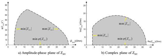
Figure 7.
An example of feasible Zinv space.
Figure 8 explains the steps of interoperability evaluation using the impedance index Zinv. Note that Zinv is merely one of the evaluation indices, and it mainly evaluates the power capability of the inverter.
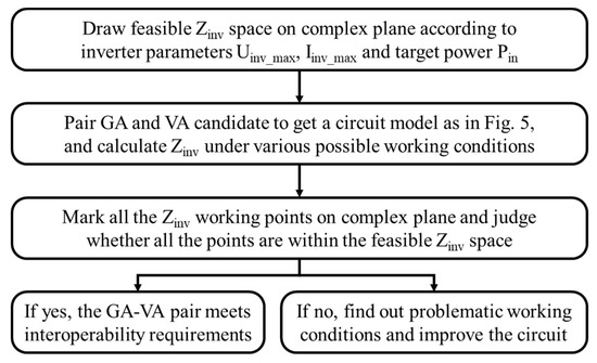
Figure 8.
Interoperability evaluation for GA and VA candidate using Zinv.
3.3. Interoperability Evaluation Index II: ZS/ZP
The power Equation (9) indicates that when diverse GAs and VAs are paired, the coil currents could change due to variation in circuit topology and parameters, even if the target power does not change. As a result, GA and VA coil currents may exceed their limit. Based on this fact, the role of ZS/ZP is to convert current limitations of GA and VA coils into safe impedance area of the circuit. An important difference between the two evaluation indices is that the feasible space of Zinv is completely determined by GA, whereas the feasible space of ZS/ZP is determined by GA and VA together.
Assume that the maximum currents of GA and VA coils are IP_max and IS_max, respectively.
According to Kirchhoff’s voltage law,
Hence,
where |ZS/ZP| and φ(ZS/ZP) are the amplitude and phase of ZS/ZP.
The transmission power can be expressed as
From Equations (15) and (18), the amplitude constraints of ZS/ZP are derived:
From Equation (19), the feasible impedance space of ZS/ZP is determined, and it can also be transformed into the complex plane, as shown in Figure 9.
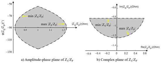
Figure 9.
An example of feasible ZS/ZP space.
Figure 10 shows the steps of interoperability evaluation using ZS/ZP, which is similar to Figure 8. The main difference is that ZS/ZP evaluates the power capability of the GA-VA coil pair. In addition, it is recommended that the evaluation process should be carried out twice, i.e., Mmax case and Mmin case.
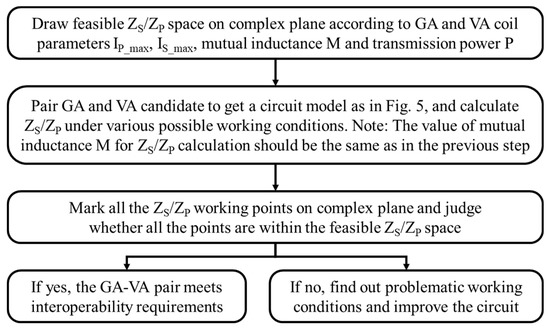
Figure 10.
Interoperability evaluation for the GA and VA candidate using ZS/ZP.
4. Interoperability Evaluation Based on Chinese WEVC Standard
In the Chinese standard for WEVC, a set of reference devices is developed with the aim to test the interoperability of market-developed devices. The reference devices include one reference GA applied to all power and ground clearance levels (WPT1~WPT3, Z1~Z3), and nine reference VAs for WPT1~WPT3, Z1~Z3, respectively [3,4]. If the market-developed device can pair up with reference devices and achieve safe charging at expected power and relative positions, it will pass the interoperability test and get market access.
However, the interoperability test between reference devices and market-developed devices requires a large cost, so it is generally carried out after the design stage. As a result, the interoperability test can hardly help improve the design of market-developed devices. This section will apply the interoperability evaluation method to reference devices, so that R&D engineers of WEVC could use it to evaluate the interoperability between their devices and reference devices, and improve their design at the early stage.
4.1. Feasible Impedance Space of Reference Devices
The double-sided LCC compensation topology is adopted in the reference devices of Chinese standard due to its good performance. The circuit diagram is shown in Figure 11, and the current and voltage limits are listed in Table 3.

Figure 11.
Reference GA-VA circuit.

Table 3.
Current and voltage limits of reference devices.
By using the method introduced in Section 3.2. and substituting the data in Table 3 into the equations, the feasible Zinv space can be obtained, as displayed in Figure 12. The feasible Zinv space of WPT1~WPT3 appears as a similar shape, which is a part of a circle. As the power level increases, the feasible space shrinks significantly.
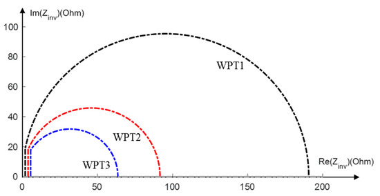
Figure 12.
Feasible impedance space of Zinv under different power levels.
Similarly, the feasible ZS/ZP space can also be obtained based on Equation (19). Note that different mutual inductances result in different feasible ZS/ZP space, so the feasible ZS/ZP spaces at Z1(Mmax, Mmin), Z2(Mmax, Mmin), Z3(Mmax, Mmin) are displayed separately. In addition, transmission power is also involved in Equation (19). The feasible ZS/ZP spaces are displayed in Figure 13. They all appear a shape of circular segment. The increase of power and the decrease of mutual inductance lead to a decrease in the area of the feasible space.
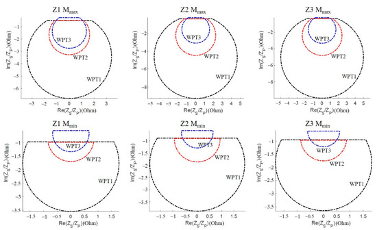
Figure 13.
Feasible impedance space of ZS/ZP under different power and ground clearance levels.
4.2. An Application Example: Evaluate Interoperability between Reference GA and VA
As a reference device for interoperability test, the reference GA-VA pair is supposed to be interoperable. Therefore, the Zinv and ZS/ZP points of the reference GA-VA pair should be within their corresponding regions. In the following part, the impedance points will be calculated according to the circuit parameters and test conditions published in the standard.
Since the parameters of the compensation network have been listed in the standard documents, it will not be repeated here. It is worth mentioning that the battery load and rectifier can be regarded as a load resistance, and its value depends on the operating condition of battery and rectifier. As stated in the standard document, the battery voltage range is set to 320~450 V. Assuming that the duty cycle of the rectifier D = 100% regardless of whether the battery voltage is at the maximum or minimum, and the load resistances are:
Accordingly, the impedance points of reference GA-VA pair are scattered over the impedance space, as shown in Figure 14, Figure 15, Figure 16 and Figure 17.
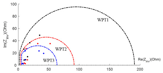
Figure 14.
Zinv operating points of reference GA-VA system (Ubat_min, D = 100%).
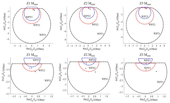
Figure 15.
ZS/ZP operating points of reference GA-VA system (Ubat_min, D = 100%).
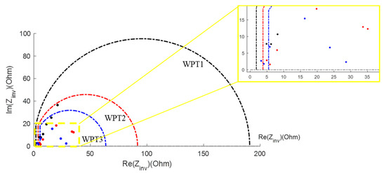
Figure 16.
Zinv operating points of reference GA-VA system (Ubat_max, D = 100%).
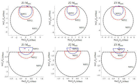
Figure 17.
ZS/ZP operating points of reference GA-VA system (Ubat_max, D = 100%).
Figure 14 and Figure 15 are Zinv and ZS/ZP points at minimum battery voltage. It can be found that all Zinv and ZS/ZP points are within their feasible range at corresponding power levels, except that a ZS/ZP point at WPT3/Z1 (Mmin) is out of the range slightly. The out-of-range point means when the reference GA-VA pair (WPT3/Z1) operates at minimum battery voltage and minimum coupling position, the GA coil current IP can exceed its limit slightly (3% estimated). Fortunately, the current margin of coil will ensure the normal operation of the system.
Figure 16 and Figure 17 are Zinv and ZS/ZP points at maximum Ubat and 100% rectifier duty cycle. There are 2/18 Zinv points and 16/18 ZS/ZP points out of range. This result indicates that as the battery voltage rises, if the controller does not regulate down the duty cycle of rectifier, Zinv and ZS/ZP will deviate from the ideal operating state, and cause voltages and currents to exceed the safe range.
As the battery voltage rises, reducing the duty cycle can narrow down the variation of load resistance, so that the Zinv and ZS/ZP points can get closer to minimum Ubat situation. Figure 18 and Figure 19 are Zinv and ZS/ZP points at maximum Ubat and 56% rectifier duty cycle. Under such conditions the load resistance is
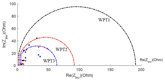
Figure 18.
Zinv operating points of reference GA-VA system (Ubat_max, D = 56%).
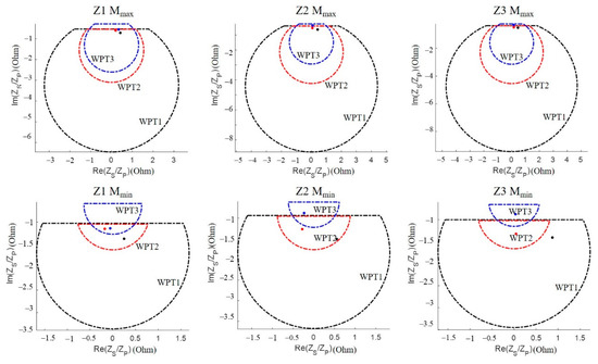
Figure 19.
ZS/ZP operating points of reference GA-VA system (Ubat_max, D = 56%).
The figures show that all points return to their feasible range.
This analysis proves the significance of introducing a controlled rectifier into the WEVC system. It also proves that the reference devices provided by Chinese standard are able to achieve the requirements of power capability.
Full power tests are conducted to demonstrate the interoperability of the reference GA and VA devices. Table 4 lists the output power achieved in the lab, including all power and ground clearance levels. The tests cover the extremum of coupling conditions and battery voltages, and all results show sufficient power capability.

Table 4.
Full power interoperability test data.
5. Conclusions and Discussions
A wireless electric vehicle charging system includes coils, compensation networks, and converters. No matter what coil configurations and compensation topologies are adopted, the coil system can be regarded as a storage and transmission system of electromagnetic energy. Two types of energy are stored dynamically in the system, including the energy of self-induced flux and energy of mutual induced flux. The former flows in to one side of the coil, whereas the latter flows through both sides and transfer power from one to the other. Accordingly, frequency, amplitudes, and phase difference of coil currents, as well as the mutual inductance of coils are determinants of transmission power.
Various coil configurations and compensation topologies bring about the problem of interoperability, which means ground assemblies (GA) and vehicle assemblies (VA) can achieve a wireless power transmission that meets the performance and functional requirements, especially the power requirement. This paper proposes an electrical interoperability evaluation method based on two impedance indices. Zinv is adopted to ensure the safety of the inverter, and ZS/ZP is adopted to make sure the coil currents are within their limits. Feasible ranges of Zinv and ZS/ZP are obtained based on a set of reference devices in Chinese standard. The results of interoperability evaluation and experiments show that the reference devices are able to achieve the requirements of power capability. Moreover, it is necessary to reduce the duty cycle of the rectifier when the battery voltage rises so as to narrow down the variation of load resistance and avoid dangerous working conditions.
Supplementary Materials
The following are available online at https://www.mdpi.com/article/10.3390/wevj12040245/s1, experimental data of interoperability test.
Author Contributions
Conceptualization, B.S. and F.Y.; methodology, B.S. and F.Y.; software, B.S.; validation, B.W. and F.Y.; formal analysis, B.S.; investigation, B.S.; resources, B.W. and F.Y.; data curation, B.S.; writing—original draft preparation, B.S.; writing—review and editing, F.Y. and M.O.; visualization, B.S.; supervision, F.Y. and M.O.; project administration, F.Y.; funding acquisition, M.O. All authors have read and agreed to the published version of the manuscript.
Funding
This research was funded by the International Science and Technology Cooperation of China, grant number 2019YFE0100200.
Institutional Review Board Statement
Not applicable.
Informed Consent Statement
Not applicable.
Data Availability Statement
The data presented in this study are available in the supplementary material.
Conflicts of Interest
The authors declare no conflict of interest.
References
- Bi, Z.; Kan, T.; Mi, C.; Zhang, Y.; Zhao, Z.; Keoleian, G.A. A review of wireless power transfer for electric vehicles: Prospects to enhance sustainable mobility. Appl. Energy 2016, 179, 413–425. [Google Scholar] [CrossRef] [Green Version]
- National Technical Committee of Auto Standardization. Electric Vehicle Wireless Power Transfer—Part 1: General Requirements; GB/T 38775.1-2020; Standards Press of China: Beijing, China, 2020. [Google Scholar]
- China Electricity Council. Electric Vehicle Wireless Power Transfer—Part 3: Specific Requirements; GB/T 38775.3-2020; Standards Press of China: Beijing, China, 2020. [Google Scholar]
- China Electricity Council. Electric Vehicle Wireless Power Transfer—Part 6: Interoperability Requirements and Testing—Ground Side; GB/T 38775.6-2021; Standards Press of China: Beijing, China, 2021. [Google Scholar]
- National Technical Committee of Auto Standardization. Electric Vehicle Wireless Power Transfer—Part 7: Interoperability Requirements and Testing—Vehicle Side; GB/T 38775.7-2021; Standards Press of China: Beijing, China, 2021. [Google Scholar]
- Hybrid-EV Committee. Wireless Power Transfer for Light-Duty Plug-In/Electric Vehicles and Alignment Methodology; SAE TIR J2954_202010; SAE International: New York, NY, USA, 2020. [Google Scholar]
- Shevchenko, V.; Husev, O.; Strzelecki, R.; Pakhaliuk, B.; Poliakov, N.; Strzelecka, N. Compensation Topologies in IPT Systems: Standards, Requirements, Classification, Analysis, Comparison and Application. IEEE Access 2019, 7, 120559–120580. [Google Scholar] [CrossRef]
- Rim, C.T.; Mi, C. Wireless Power Transfer for Electric Vehicles and Mobile Devices; John Wiley & Sons: Hoboken, NJ, USA, 2017. [Google Scholar]
- Chen, K.; Zhao, Z.; Liu, F.; Yuan, L. Analysis of Resonant Topology for Bi-directional Wireless Charging of Electric Vehicle. Autom. Electr. Power Syst. 2017, 41, 66–72. [Google Scholar]
- Ramezani, A.; Farhangi, S.; Iman-Eini, H.; Farhangi, B.; Rahimi, R.; Moradi, G.R. Optimized LCC-Series Compensated Resonant Network for Stationary Wireless EV Chargers. IEEE Trans. Ind. Electron. 2019, 66, 2756–2765. [Google Scholar] [CrossRef]
- Mai, R.; Chen, Y.; Zhang, Y.; Yang, N.; Cao, G.-Z.; He, Z. Optimization of the Passive Components for an S-LCC Topology-Based WPT System for Charging Massive Electric Bicycles. IEEE Trans. Ind. Electron. 2018, 65, 5497–5508. [Google Scholar] [CrossRef]
- Schneider, J.; Kamichi, K.; Mikat, D.; Sutton, R.; Abdul-Hak, M.; Minagawa, Y.; Abeta, H.; Taha, E.; Boyer, R.; Sirota, J.; et al. Bench Testing Validation of Wireless Power Transfer up to 7.7 kW Based on SAE J2954. SAE Int. J. Passeng. Cars-Electron. Electr. Syst. 2018, 11, 89–108. [Google Scholar] [CrossRef]
- Schneider, J.; Carlson, R.; Sirota, J.; Sutton, R.; Taha, E.; Kesler, M.; Kamichi, K.; Teerlinck, I.; Abeta, H.; Minagawa, Y.; et al. Validation of Wireless Power Transfer up to 11 kW Based on SAE J2954 with Bench and Vehicle Testing; SAE Technical Paper; SAE International: New York, NY, USA, 2019. [Google Scholar]
Publisher’s Note: MDPI stays neutral with regard to jurisdictional claims in published maps and institutional affiliations. |
© 2021 by the authors. Licensee MDPI, Basel, Switzerland. This article is an open access article distributed under the terms and conditions of the Creative Commons Attribution (CC BY) license (https://creativecommons.org/licenses/by/4.0/).