Article

Parity–Time Symmetric Model and Analysis for Stable Multi-Load Wireless Power Transfer

State Key Laboratory of Electrical Insulation and Power Equipment, Xi’an Jiaotong University, Xi’an 710049, China
*
Author to whom correspondence should be addressed.
World Electr. Veh. J. 2021, 12(4), 226; https://doi.org/10.3390/wevj12040226
Submission received: 25 September 2021 / Revised: 19 October 2021 / Accepted: 29 October 2021 / Published: 9 November 2021

Abstract

:
A noticeable challenge for a multi-load wireless power transfer system is to achieve stable power transfer under a dynamic change in coupling conditions. It was proposed that the parity–time symmetric wireless power transfer (PT-WPT) system can achieve stable output efficiency for a single receiver when tuned at the purely real eigenfrequency. However, in the case of higher order, PT symmetric systems usually cannot maintain the real eigenfrequency. To address the issue, a high-order PT-WPT model was established using coupled mode theory (CMT) theory in this paper, and the eigenfrequency of the multi-load PT-WPT system was analyzed. Here, we propose that, theoretically, the system can work at the purely real eigenfrequency by impedance matching. The transfer efficiency of the multi-load PT-WPT system when the system works at the real eigenfrequency was analyzed. The results of the numerical simulation show that the multi load PT-WPT system can maintain stable output efficiency under a dynamic change in coupling conditions. In the long run, our work provides a new possibility for the stable transmission of the multi-load wireless power transfer system.

1. Introduction

Wireless power transfer technology can provide energy for electronic devices without a power cord, which is conducive to improving charging flexibility. Presently, wireless power transfer is widely used in consumer electronics, electric vehicles, and implantable sensors [1,2,3,4,5,6]. However, current studies mainly focus on single load scenarios. With the increasing number of wireless power transfer scenarios, how to provide energy for multiple loads at the same time has become a research hotspot in the field of wireless power transfer.
In order to meet the wireless power supply demand for the multi-load scenario, a few studies have been conducted. Firstly, increasing the area of transmitting coils is a simple method to provide power to multiple loads, but a single transmitting coil limits the spatial freedom of the receiving coils [7,8]. In [9], the energy is transmitted to multiple receivers by constructing a transmitting coil array to increase the spatial freedom of the receiving coils, while the mutual inductance between transmitting coils will reduce the efficiency of the system. To solve this problem, an omnidirectional WPT system using three orthogonal coils as transmitters was proposed [10,11]. Orthogonal coils could avoid mutual inductance between transmitting coils. However, the efficiency of the system will be affected significantly by the position of the receiving coils. Similar works have been conducted in [12,13,14]. However, such problems have not been resolved. Furthermore, for the commonly used power transfer scheme, complex topology and control strategy are necessary under a dynamic change in coupling conditions.
Parity–time symmetry is a theory from quantum mechanics, which has a very wide range of applications in nonlinear optics. A PT-symmetric system usually has two phases. In the exact phase, the eigenfrequency of the system is a real number, and the energy can flow uniformly and repeatedly between the gain region and the attenuation region. In the broken phase, the energy of the gain region and attenuation region will change exponentially [15]. Assawaworrarit et al. first applied it to wireless power transfer and proposed a classical second-order PT-WPT model, which realized the stability of transmission efficiency in the range of 1 m through the frequency-tracking method using the characteristics of the PT symmetric system in the exact phase [16]. Then, Zhou et al. used a self-excited controlled inverter to increase the output power of the PT-WPT system to hundreds of watts [17]. However, their studies only considered the case of one load. Zeng et al. extended the parity–time symmetry to a higher-order domain, and proposed a PT-WPT system with relay coil [18]. Luo et al. established the model of the multiload PT-WPT system using the circuit theory [19], but they only analyzed the transfer characteristics and power distribution of the system under the second-order condition, and the characteristics of the PT-WPT system under greater load conditions were not analyzed. Therefore, it is of great significance to study the output characteristics of the PT-WPT system in the high-order case to build a stable multi-load wireless power transfer system.
The main contribution of this paper is the proposal of a high-order PT-symmetric scheme for the WPT system with any receivers. In this paper, a CMT model of the multi-load PT-WPT system was established and the eigenfrequency of the system was solved. Notably, the eigenfrequency cannot spontaneously remain real in the multi-load PT-WPT system. To make the system work at the real eigenfrequency, a practical and simple impedance matching strategy was proposed. In addition, the efficiency of the multi-load PT-WPT system with a different number of loads was analyzed in detail. In this research, the multi-load PT-WPT system can work at the real eigenfrequency stably and efficiently, especially in the weak coupling region, which means a wider range of axial transfer distances and lateral misalignment for multiple loads.
This paper is organized as follows. In Section 2, a high-order PT-WPT model is established using coupled mode theory (CMT) theory. In Section 3, the eigenfrequency of the multi-load PT-WPT system is analyzed and a specific impedance matching strategy is described. In Section 4, the efficiency of the multi-load PT-WPT system with different numbers of loads is analyzed by numerical simulation. In Section 5, a conclusion is drawn, and a future application of the proposed method is suggested.

2. Materials and Methods

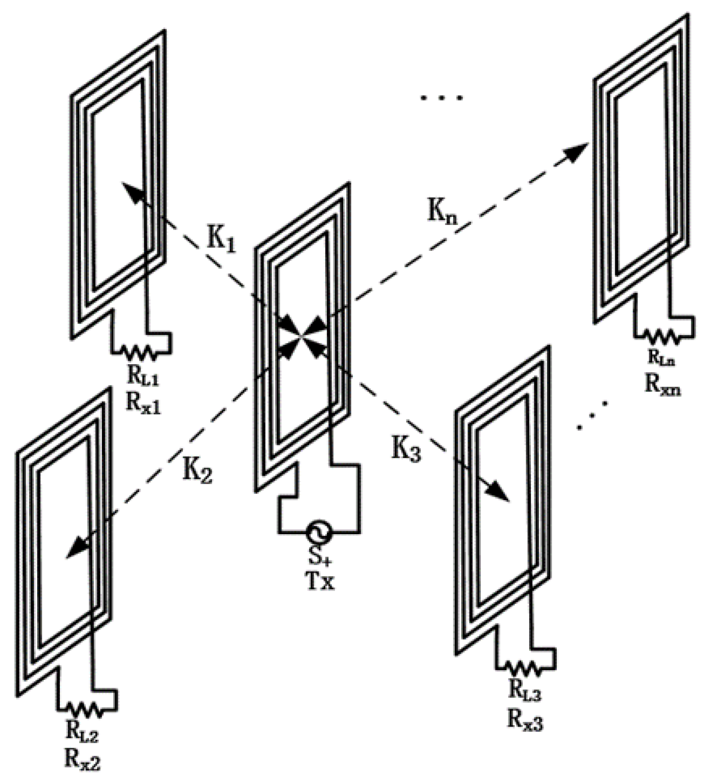
2.1. Coupled Mode Equation of the Multi-Load WPT System

The schematic diagram of the multi load WPT system is shown in Figure 1. The system consists of a transmitting coil TX and n receiving coils Rx. The coupled mode theory is a powerful tool to study the power and efficiency of the system in the strong coupling state [20,21]. The input of the system is S+, and the coupled mode equation of the system can be expressed as follows [22]:
d a 0 d t = ( j ω 0 + Γ 0 + Γ L 0 ) a 0 + 1 n j k i a i + S + d a i d t = ( j ω 0 + Γ i + Γ L i ) a i + i m j k i m a m + j k i a 0
where |a0|2 and |ai|2 correspond to the energy in the transmitting coil and the i-th receiving coil, respectively; ω0 is the resonant frequency of the resonant coil; ki is the coupling rate of the transmitting coil and the i-th receiving coil; and kim is the coupling rate between the i-th receiving coil and the m-th receiving coil. It is assumed that the coupling rate between the receiving coils can be negligible. Γi is the load loss of the i-th coil and ΓLi is the loss of the i-th coil itself.
They have the following relationships:
Γ L 0 = R L 0 2 L i , Γ 0 = R 0 2 L i , Γ L i = R L i 2 L i , Γ i = R i 2 L i , k i = ω 0 K i 2
where Ki is the coupling coefficient between transmitting coil and the i-th receiving coil, Ri is the load resistance, Li is the inductance of receiving coil, and −R0 is the equivalent negative resistance of transmitter.

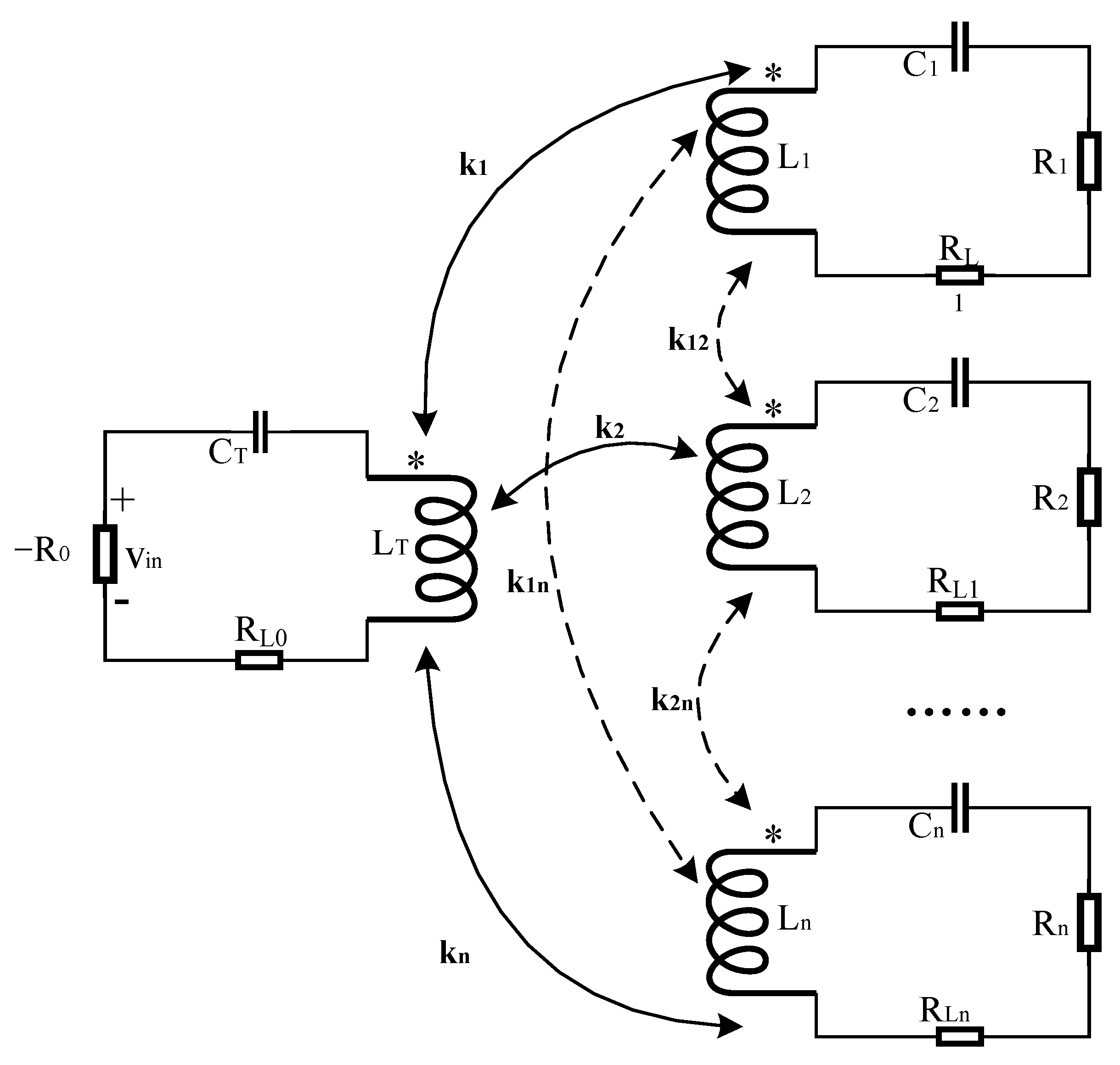
2.2. High-Order Multi-Load PT-WPT System

The characteristic equation of the PT symmetric system can remain unchanged when parity and time are reversed. The single load nonlinear PT-WPT symmetric model can be realized using an operational amplifier to construct negative resistance. Figure 2a shows the structural diagram of negative resistance, which is realized by an operational amplifier and three resistors. Figure 2b shows the equivalent circuit diagram of the PT-WPT system.
Owing to the saturation voltage of the operational amplifier, the structure in Figure 2a is equivalent to a nonlinear negative resistance R0, which is
R 0 = R f 1 R f 3 R f 2
The equivalent negative resistance −R0 will act as a power supply, input the power to the resonant circuit at the transmitter, and then complete the power transmission through the magnetic coupling between the transmitter and the receiver.
In order for the system to be in PT symmetrical state, the parameters at both transmitter and receivers need to remain unchanged when time and parity are reversed at the same time, which means that the gain rate of the equivalent circuit should be equal to the loss rate. Thus, the equivalent circuit needs to meet the following constraints [18]:
{ ω T = ω R = ω 0 R 0 + R L 0 L T = R L 1 + R 1 L R
where ωT is the resonant frequency of transmitting coil and ωR is the resonant frequency of the receiving coil. On this basis, we proposed a model for the multi-load PT-WPT system. The circuit structure diagram of the series PT-WPT system with n-loads is shown in Figure 3.
According to the theory in [21], in order to obtain a PT symmetric wireless power transfer system, the parameters of the transmitting coil and the receiving coils should be symmetrical, and the following conditions should be met:
Γ 0 + Γ L 0 = Γ i Γ L i , Γ L 0 = Γ L i

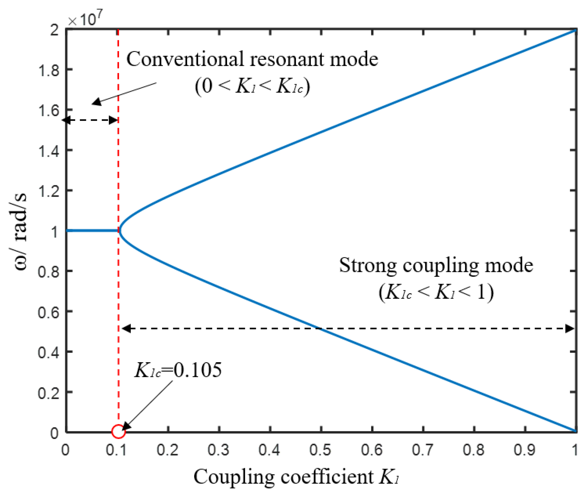
3. Analysis of the Eigenfrequency of the Multi-Load PT-WPT System

Using the methods in [20], we set a zero return wave to achieve the zero reflection states. In this case, the equivalent eigenfrequency can be obtained:
H ( a 0 a 1 a n ) = j ω ( a 0 a 1 a n )
where the Hamiltonian is
H = ( j ω 0 + Γ 0 + Γ L 0 j k 1 j k 2 j k n j k 1 j ω 0 + Γ 1 + Γ L 1 0 0 j k 2 0 j ω 0 + Γ 2 + Γ L 2 0 j k n 0 0 j ω 0 + Γ n + Γ L n )
To find the eigenfrequency, we solve the equation |HjωI| = 0 (where I is an identical matrix). Assuming Γ0 + ΓL0 = Γ′0, the Hamiltonian can be written as follows:
H = ( j ω 0 + Γ 0 j k 1 j k 2 j k n j k 1 j ω 0 Γ 0 0 0 j k 2 0 j ω 0 Γ 0 0 j k n 0 0 j ω 0 Γ 0 )
To find the eigenfrequency, the equation |HjωI| = 0 (where I is an identical matrix) should be solved.
After matrix transformation, we can write the HjωI as follows:
H j ω I = ( j Δ ω + Γ 0 + i = 1 n k i 2 [ j Δ ω Γ 0 ] n j k 1 j k 2 j k n 0 j Δ ω Γ 0 0 0 0 0 j Δ ω Γ 0 0 0 0 0 j Δ ω Γ 0 )
where Δω = ω0ω, then the characteristic equation can be obtained:
[ j ( ω 0 ω ) + Γ 0 ] [ j ( ω 0 ω ) Γ 0 ] n + i = 1 n k i 2 = 0
Ignoring the loss of the coil itself (ΓL0), when n = 1, the characteristic equation can be written as follows:
[ j ( ω 0 ω ) + Γ 0 ] [ j ( ω 0 ω ) Γ 0 ] + k 1 2 = 0
The eigenfrequencies of PT-WPT system are as follows:
ω = ω 0 ± k 1 2 Γ 0 2
When n = 1, the system is a one-load WPT system. At this time, it does not need to meet the phase condition and impedance matching operation to make the system run at the eigenfrequency. The system can run stably at the exact phase only with a nonlinear initial gain [23]. According to Formula (12), when the resonant angular frequency = 1 × 10⁷ rad/s, Ri = 50 Ω, Li = 50 μH, RLi = 2.5 Ω, and the coupling coefficient K of the three receiving coils varies from 0 to 1. The eigenfrequencies of the PT-WPT system are shown in Figure 4 (Using Matlab 2020b).
From Figure 4, it can be observed that there are two states in the system: the strong coupling mode and conventional resonant mode. The strong coupling mode is called the PT symmetric region (k1 ≥ Γ’0), which means the system is run at the exact phase. In this region, the gain coefficient and loss coefficient are equal, while the other region is the conventional resonant mode (k1 < Γ’0).
When n > 1, in order to obtain the solutions of the characteristic equation, both the phase condition and the amplitude condition must be satisfied. The first step is to determine the real solutions of the eigenfrequency, and Equation (8) can be written as follows:
[ ( ω 0 ω ) 2 + Γ 0 2 ] [ j ( ω 0 ω ) Γ 0 ] n 1 = i = 1 n k i 2
After transformation, it can be changed into the following:
( ( ω 0 ω ) 2 + Γ 0 2 ) n 1 [ j ( ω 0 ω ) Γ 0 ( ω 0 ω ) 2 + Γ 0 2 ] n 1 = i = 1 n k i 2 ( ω 0 ω ) 2 + Γ 0 2
Therefore, the real solutions of the eigenfrequency should satisfy the following requirements:
( ( ω 0 ω ) 2 + Γ 0 2 ) n 1 [ ( ω 0 ω ) 2 + Γ 0 2 ] = i = 1 n k i 2
On this basis, the eigenfrequency of the system can be obtained as follows:
ω = ω 0 ± i = 1 n k i 2 n + 1 Γ 0 2
The stable eigenfrequency can be obtained only when the following specific conditions are satisfied:
( ω 0 ω ) Γ 0 = sin ( k π n 1 ) , k is   an   integer
In other words, when the coupling coefficient changes, the resistance parameters of the circuit need to be adjusted to ensure that the PT-WPT system always works at the intrinsic frequency. Combining Equations (16) and (17), we can get the rules of impedance matching as follows:
Γ 0 = i = 1 n k i 2 n + 1 1 + sin 2 ( k π n 1 ) , k is   an   integer
The critical condition for the circuit in strong coupling state is Γ’0 > ΓLi.
Substituting Formulas (2) and (5) into Formula (18), the resistance value that makes the PT symmetrical wireless power transfer system stable can be deduced as follows:
R 0 = 2 L i Γ 0 + R L 0 , R i = 2 L i Γ 0 R L 0
Only when the impedance of the system meets the condition of Formula (19) does the multi-load PT-WPT system have real solutions. At this point, the real solutions of eigenfrequency can be rewritten as follows:
ω = ω 0 ± sin 2 ( k π n 1 ) i = 1 n k i 2 n + 1 1 + sin 2 ( k π n 1 ) , k is   an   integer
Taking n = 3 as an example, the resonant frequency of the coil is set to 100 kHz, and the coupling rate K of the three receiving coils varies from 0 to 0.2. The change in eigenfrequency of the three-load PT-WPT system under this control method is shown in Figure 5.
As shown in Figure 5, the multi-load PT-WPT system has two eigenfrequencies, both being purely real when using the impedance matching strategy according to Formula (19). This means the system satisfies the PT symmetry condition and energy can flow efficiently between the gain region and the loss region without frequency tracking. From this point of view, such a PT-WPT system can be regard as a highly practical WPT strategy.

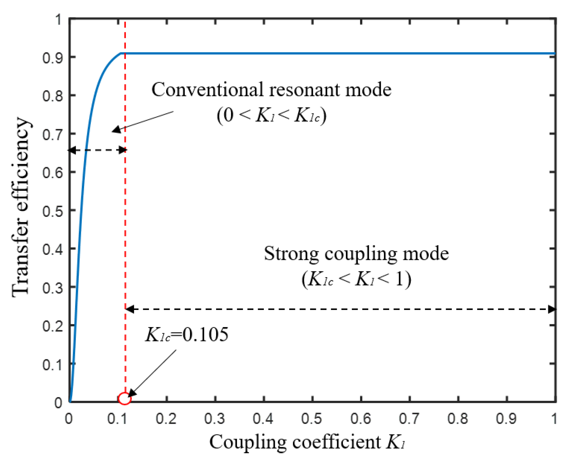
4. The Efficiency of the PT-WPT System

According to the above analysis of the single-load PT-WPT system, when the frequency is ω = ω0 and the gain coefficient is Γ10 + k2 / Γ’0, the efficiency expression of the single-load PT-WPT system in the conventional resonant mode and the strong coupling mode can be obtained as follows:
η = Γ 1 | a 1 | 2 Γ L 0 | a 0 | 2 + ( Γ 1 + Γ L 1 ) | a 1 | 2 = { Γ 1 Γ L 0 + Γ 1 + Γ L 1 k 1 Γ 0 k 2 Γ 1 [ Γ L 0 ( Γ 1 + Γ L 1 ) + k 2 ] ( Γ 1 + Γ L 1 ) k 1 < Γ 0
When the resonant angular frequency = 1 × 10⁷ rad/s, Ri = 50 Ω, Li = 50 μH, RLi = 2.5 Ω, and the coupling coefficient K of the three receiving coils varies from 0 to 1. The transfer characteristics of the PT-WPT system when n = 1 are shown in Figure 6.
According to Figure 6, when k1 < 0.105, the system is in the conventional resonant mode, and the system efficiency changes with the value of k1. After the coupling coefficient reaches 0.105, the system can maintain stable operation efficiency, which is only related to the inherent parameters.
When n > 1, because of the phase angle requirement in the eigenfrequency characteristic equation, the impedance should be matched both at the transmitting and the receiving ends to make the circuit work at the eigenfrequency required by PT symmetry. When Γ’0 > ΓLi, the system is in strong coupling mode and its efficiency can be expressed as follows:
η = i = 1 n Γ i Γ L 0 + i = 1 n ( Γ i + Γ L i )
According to Formulas (2) and (18), we can find that the condition for the stable existence of strong coupling region is as follows:
i = 1 n k i 2 n + 1 > Γ 0 2
Taking n = 3 as an example, the resonant frequency of the coil is set to 10 MHz, and Li is 100 mH and RLi is 0.5 Ω. At this time, Γ’0 > 2.5, when ΣKi2 > 1.525 × 10³, the system can be maintained in strong coupling mode. In order to analyze the transfer efficiency of the system when one of the receivers changes, we assume the coupling coefficient K2 and K3 = 0.2, and the coupling coefficient K1 of the first receiving coils varies from 0 to 1. We compare the efficiency of the system with that of the wireless power transfer system working at the resonant frequency, of which the value of load resistance is 10 Ω, and the results are shown in Figure 7.
From Figure 7, compared with the wireless power transfer system working at the resonant frequency, one sees that the transfer efficiency of the multi load PT-WPT system is significantly higher than that of the traditional WPT system when the coupling coefficient is low. When the coupling coefficient is high, both the PT-WPT system and traditional WPT system can achieve more than 90% efficiency. Another very important advantage of the multi-load PT-WPT system is that it can achieve stable transmission efficiency in a large range without frequency tracking, which cannot be achieved by traditional methods. From this point of view, this high-order system can be regarded as an efficient and practical new WPT strategy.

5. Conclusions

In this paper, a stable and highly efficient PT-WPT system for multi-load was proposed. By employing a series-series topology and a negative resistance structure, a multi-load PT-WPT system with high reliability and low complexity was established. The corresponding CMT (coupled mode theory) model was derived and solved by introducing complex variables and by setting a zero return wave. Thus, closed-form expressions for eigenfrequencies, transfer efficiency, and critical condition were provided. By a special impedance matching strategy, the multi-load PT-WPT system can work at the purely real eigenfrequency, which means energy can flow stably among transmitters and receivers. The numerical simulation results show that this PT-WPT system can work stably in the exact phase and the stability of transfer efficiency with the multi-load PT-WPT system is significantly superior to that of traditional methods, especially when the coupling coefficient is low. This means that the multi-load PT-WPT system can have a wide range of axial transfer distances and lateral misalignment.

Author Contributions

Conceptualization, M.R. and H.Y.; methodology, X.W. and A.Y.; software, R.Z.; validation, Z.Z., and R.Z.; formal analysis, Z.Z.; investigation, H.Y.; resources, H.Y.; data curation, Z.Z.; writing—original draft preparation, Z.Z.; writing—review and editing, H.Y.; visualization and supervision, Z.Z. and R.Z. All authors have read and agreed to the published version of the manuscript.

Funding

This research was funded by Shaanxi Natural Science Basic Research Program (2021JQ-041), State Key Laboratory of Electrical insulation and Power Equipment (EIEP21306).

Institutional Review Board Statement

Not applicable.

Informed Consent Statement

Not applicable.

Data Availability Statement

The data presented in this study are available on request from the corresponding author.

Conflicts of Interest

The authors declare no conflict of interest.

References

  1. Du, S.; Chan, E.K.; Wen, B.; Hong, J.; Widmer, H.; Wheatley, C.E. Wireless power transfer using oscillating magnets. IEEE Trans. Ind. Electron. 2017, 65, 6259–6269. [Google Scholar] [CrossRef]
  2. Li, Z.; Zhu, C.; Jiang, J.; Song, K.; Wei, G. A 3-kw wireless power transfer system for sightseeing car supercapacitor charge. IEEE Trans. Power Electron. 2017, 32, 3301–3316. [Google Scholar] [CrossRef]
  3. Hasaba, R.; Okamoto, K.; Kawata, S.; Eguchi, K.; Koyanagi, Y. Magnetic Resonance Wireless Power Transfer Over 10 m With Multiple Coils Immersed in Seawater. IEEE Trans. Microw. Theory Tech. 2019, 67, 4505–4513. [Google Scholar] [CrossRef]
  4. Li, K.; Ni, W.; Duan, L.; Abolhasan, M.; Niu, J. Wireless power transfer and data collection in wireless sensor networks. IEEE Trans. Veh. Technol. 2017, 67, 2686–2697. [Google Scholar] [CrossRef] [Green Version]
  5. Elkhatiri, A.; Oumidou, N.; Labbadi, M.; Lhayani, M.; Cherkaoui, M. Magnetic Chargers in Electrical Models: Operating Principle and Efficiency Analysis of an Inductively Coupled Power Transfer System. In Proceedings of the Digital Technologies and Applications. ICDTA 2021, Fez, Morocco, 29–30 January 2021; Volume 211, pp. 1561–1572. [Google Scholar]
  6. Oumidou, N.; Elkhatiri, A.; Khalil, S.; Labbadi, M.; Cherkaoui, M. Comparison Study of the Resonant Inductive Power Transfer for Recharging Electric Vehicles. In Proceedings of the Digital Technologies and Applications. ICDTA 2021, Fez, Morocco, 29–30 January 2021; Volume 211, pp. 1549–1559. [Google Scholar]
  7. Ahn, D.; Kim, S.M.; Kim, S.W.; Moon, J.I.; Cho, I.K. Wireless power transfer receiver with adjustable coil output voltage for multiple receivers application. IEEE Trans. Power Electron. 2019, 66, 4003–4012. [Google Scholar] [CrossRef]
  8. Fu, M.; Yin, H.; Ma, C. Megahertz Multiple-Receiver Wireless Power Transfer Systems with Power Flow Management and Maximum Efficiency Point Tracking. IEEE Trans. Microw. Theory Tech. 2017, 65, 4285–4293. [Google Scholar] [CrossRef]
  9. Kim, S.; Lee, B. Control of magnetic field distribution by excitation phases of transmitters in MIMO WPT system. In Proceedings of the URSI Asia-Pacific Radio Science Conference (URSI AP-RASC), Seoul, Korea, 21–25 August 2016; pp. 861–863. [Google Scholar]
  10. Lin, D.; Zhang, C.; Hui, S.Y.R. Mathematic analysis of omnidirectional wireless power transfer—Part-I: Two-Dimensional Systems. IEEE Trans. Power Electron. 2017, 32, 625–633. [Google Scholar] [CrossRef]
  11. Lin, D.; Zhang, C.; Hui, S.Y.R. Mathematic analysis of omnidirectional wireless power transfer—part-II three-dimensional systems. IEEE Trans. Power Electron. 2017, 32, 613–624. [Google Scholar] [CrossRef]
  12. Zhu, Q.; Su, M.; Sun, Y.; Tang, W.; Hu, A.P. Field Orientation Based on Current Amplitude and Phase Angle Control for Wireless Power Transfer. IEEE Trans. Ind. Electron. 2018, 65, 4758–4770. [Google Scholar] [CrossRef]
  13. Han, H.; Mao, Z.; Zhu, Q.; Su, M.; Hu, A.P. A 3D Wireless Charging Cylinder With Stable Rotating Magnetic Field for Multi-Load Application. IEEE Access 2019, 7, 35981–35997. [Google Scholar] [CrossRef]
  14. Feng, J.; Li, Q.; Lee, F.C. Coil and Circuit Design of Omnidirectional Wireless Power Transfer System for Portable Device Application. In Proceedings of the 2018 IEEE Energy Conversion Congress and Exposition (ECCE), Portland, OR, USA, 23–27 September 2018; pp. 914–920. [Google Scholar]
  15. Kawabata, K.; Shiozaki, K.; Ueda, M.; Sato, M. Symmetry and Topology in Non-Hermitian Physics. Phys. Rev. X 2018, 9, 041015. [Google Scholar] [CrossRef] [Green Version]
  16. Assawaworrarit, S.; Yu, X.; Fan, S. Robust wireless power transfer using a nonlinear parity-time-symmetric circuit. Nature 2017, 546, 387–390. [Google Scholar] [CrossRef]
  17. Zhou, J.; Zhang, B.; Xiao, W.; Qiu, D.; Chen, Y. Nonlinear Parity-Time-Symmetric Model for Constant Efficiency Wireless Power Transfer: Application to a Drone-in-Flight Wireless Charging Platform. IEEE Trans. Ind. Electron. 2018, 66, 4097–4107. [Google Scholar] [CrossRef]
  18. Zeng, C.; Sun, Y.; Li, G.; Li, Y.; Jiang, H.; Yang, Y.; Chen, H. High-Order Parity-Time Symmetric Model for Stable Three-Coil Wireless Power Transfer. Phys. Rev. Appl. 2020, 13, 034054. [Google Scholar] [CrossRef]
  19. Luo, C.; Qiu, D.; Lin, M.; Zhang, B. Circuit Model and Analysis of Multi-Load Wireless Power Transfer System Based on Parity-Time Symmetry. Energies 2020, 13, 3260. [Google Scholar] [CrossRef]
  20. Bou-Balust, E.; Hu, A.P.; Alarcon, E. Scalability Analysis of SIMO Non-Radiative Resonant Wireless Power Transfer Systems Based on Circuit Models. IEEE Trans. Circuits Syst. I Regul. Pap. 2015, 62, 2574–2583. [Google Scholar] [CrossRef]
  21. Vinko, D.; Pavlović, I.; Runac, K. Application of DC-DC converters in loosely coupled wireless power transmission systems. In Proceedings of the 2017 International Conference on Smart Systems and Technologies (SST), Osijek, Croatia, 18–20 October 2017; pp. 51–54. [Google Scholar]
  22. Lee, K.; Cho, D.H. Analysis of Wireless Power Transfer for Adjustable Power Distribution among Multiple Receivers. IEEE Antennas Wirel. Propag. Lett. 2015, 14, 950–953. [Google Scholar] [CrossRef]
  23. Zeng, C.; Sun, Y.; Li, G.; Li, Y.; Jiang, H.; Yang, Y.; Chen, H. Enhanced sensitivity at high-order exceptional points in a passive wireless sensing system. J. Opt. Express 2019, 27, 27562–27572. [Google Scholar] [CrossRef] [PubMed]
Figure 1. Configuration of the multi-load WPT system.
Wevj 12 00226 g001
Figure 2. Single load PT-WPT system with series-series topology: (a) the negative resistance structure and (b) the equivalent circuit diagram.
Wevj 12 00226 g002
Figure 3. Multi load PT-WPT system with series-series topology.
Wevj 12 00226 g003
Figure 4. Operating frequency of the one-load PT-WPT system (the system parameters are as follows: the resonant angular frequency of the coil is set to 1 × 10⁷ rad/s, Ri is 50 Ω, Li is 50 μH, RLi is 2.5 Ω, and the coupling coefficient K of the three receiving coils varies from 0 to 1).
Wevj 12 00226 g004
Figure 5. The eigenfrequency of the three-load PT-WPT system. (a) The eigenfrequency is higher than ω0 and (b) the eigenfrequency is lower than ω0 (the system parameters are as follows: the resonant frequency of the coil is set to 100 kHz and the coupling coefficient K of the three receiving coils varies from 0 to 0.2).
Wevj 12 00226 g005
Figure 6. The transfer characteristics of the single-load PT-WPT system (the system parameters are as follows: the resonant angular frequency of the coil is set to 1 × 10⁷ rad/s, Ri is 50 Ω, Li is 50 μH, RLi is 2.5 Ω, and the coupling coefficient K of the three receiving coils varies from 0 to 1).
Wevj 12 00226 g006
Figure 7. The transfer characteristics of the multi-load PT-WPT system: (a) the impedance matching in the multi-load PT-WPT system; (b) transfer efficiency of the multi-load PT-WPT system and of the constant load WPT system (the system parameters are as follows: the resonant frequency of the coil is 10 MHz, Ri of constant load WPT system is 10 Ω, Li is 100 mH, and RLi is 0.5 Ω.
Wevj 12 00226 g007
Publisher’s Note: MDPI stays neutral with regard to jurisdictional claims in published maps and institutional affiliations.

