Abstract
Vehicle yaw stability control is an important part of the active safety of electric vehicles. In order to realize the yaw stability control of vehicles, this paper takes 4-WID electric vehicles as the research object, studies the nonlinear estimation of the state parameters of the lateral stability dynamic system and the yaw stability control strategy. The vehicle state parameter estimation strategy, based on the unscented Kalman filter (UKF) algorithm and the model predictive control algorithm, are designed to control the vehicle yaw stability, which realizes the safe and stable driving of the vehicle. Through CarSim–Simulink joint simulation and hardware-in-the-loop (HIL) experiments based on MicroAutoBox, the effectiveness and real-time performance of the designed control strategy are fully verified, which accelerate the development process of the vehicle controller, and realizes the safe and stable driving of the vehicle.
1. Introduction
With the rapid development of the automobile industry, problems such as energy crisis and environmental pollution have become increasingly apparent, and the research and development of electric vehicles has received extensive attention. The observation of vehicle state parameters [1,2] is the research basis of the vehicle dynamics control, and the accuracy of observation can determine the effectiveness of the vehicle dynamics control. Direct yaw moment control [3,4,5] can actively control the driving force of each wheel, so that the vehicle applies an additional yaw moment to control the lateral movement of the vehicle, ensuring driving safety.
Representative teams have conducted in-depth research on direct yaw moment control. Goodarzi et al. [6] introduced the optimal control theory to improve the lateral stability of the vehicle, and designed a direct yaw moment controller for a four-wheel independent hybrid electric vehicle. According to the loss of lateral stability of the vehicle in an emergency, M. Mirzaei et al. [7] designed an ideal model based on linear two degrees of freedom, and tracked the tire/road conditions through the direct yaw moment control system. Professor Zong Changfu of Jilin University [8], and others, proposed a single neuron direct yaw moment control method for the steering stability of the car under extreme conditions, and verified that this method effectively improves the car’s lateral and longitudinal stability. Professor Guo Konghui and Li Shaosong [9] proposed an improved linear time-varying model predictive control strategy for the active front-wheel steering system. At the same time, the Pacejka tire model was introduced to expand the stability range of the vehicle and improve the yaw stability of the vehicle [10]. Generally speaking, the basic research on the lateral stability control of electric vehicles has achieved good results, but the research on improving the lateral stability control system of distributed driven electric vehicles based on the direct yaw moment control is not comprehensive enough.
This paper takes the 4-WID electric vehicle as the research object, and studies the nonlinear estimation of the state parameters of the lateral stability dynamic system and the yaw stability control strategy. In the aspect of state parameter estimation, an unscented Kalman filter [11,12,13] algorithm is proposed, to jointly observe the yaw rate and the side slip angle of the center of mass; in the aspect of yaw stability control, a model predictive control method is used to improve the lateral stability of the vehicle. The real-time and accuracy of the control strategy designed in this paper, are verified by the simulation of complex conditions and the experiments of hardware-in-the-loop.
2. System Modeling
2.1. Dynamic Model Establishment
For the yaw stability control of distributed driving vehicles, a single-track model is selected for control research. The bicycle model is shown in Figure 1.
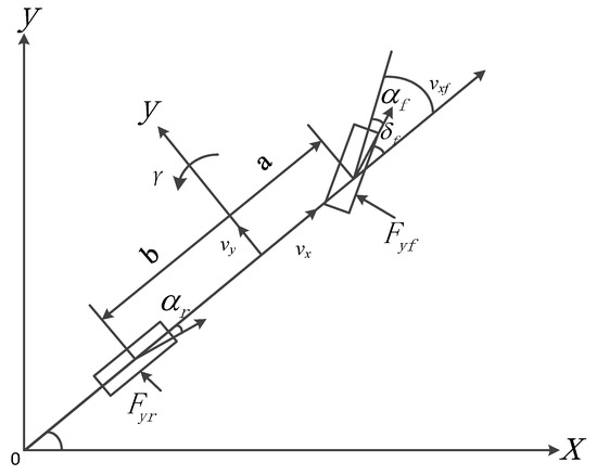
Figure 1.
Bicycle model.
Derive the kinematics equation of the car by Newton’s second law, the two-degree-of-freedom vehicle model equation is as follows:
where m is the quality of the vehicle, v is the speed, γ is the yaw rate, β is the center of mass deflection angle, a is the distance from the center of mass to the front axle, b is the distance from the rear axis to the center of mass, δ is the angle of rotation of the front wheel; Cr and Cf are the lateral rigidity of the rear axle and the front axle. When the car performs a steady-state circular motion, the tangential acceleration of the car around the circle is zero, which is .
2.2. Design of Unscented Kalman Filtering Algorithm
Unscented Kalman filtering (UKF) overcomes the shortcomings of traditional Kalman filtering and extended Kalman filtering [14]. The sampling points are used to approximate the state distribution without calculating the Jacobian matrix, and the calculation accuracy is higher. The algorithm flow is shown in Figure 2, as follows:

Figure 2.
The estimation process of UKF.
For vehicle state parameter estimation, a nonlinear discrete system is established, as follows:
where x(k)—system state matrix, z(k)—observation matrix, w(k), v(k)—system noise and measurement noise, supposing the two are uncorrelated zero-mean white noise; the specific steps of the UKF are as follows:
To construct Sigma sample points, there are the following:
where —the mean of the system state quantity; P—the variance of the state quantity. The weights of sigma points are as follows:
n is the dimension of the state vector to be estimated and λ is the scaling factor.
Calculate the predicted value, mean and variance of sigma sample points as follows:
Calculate the mean and variance of the predicted sample points as follows:
Use the unscented transform (UT) transformation to get new predicted values, as follows:
Update the mean and variance of the predicted value as follows:
Calculate the Kalman gain of UKF as follows:
State the mean and variance are updated, as follows:
The state parameter estimation system optimizes the state parameter estimation value through each iteration update, thereby reducing the system error.
2.3. Design of Yaw Stability Control
The state parameter observation method of the 4-WID electric vehicle provides support for vehicle yaw control, and takes tracking the target side slip angle and the target yaw rate as the yaw stability control target, and comprehensively optimizes the yaw stability of the vehicle.
2.3.1. Model Control Prediction Algorithm Design
The model predictive control method [15,16] is a feedback control algorithm. It is mainly composed of the following three parts: model, forecast and control. The model predictive control process is shown in Figure 3.

Figure 3.
Model predictive control algorithm flow chart.
2.3.2. The Main Steps of Model Predictive Controller Design
- (1)
- The establishment of the model.
According to the relationship between the speeds in the bicycle model, we can get the following:
The vertical load of the tire is as follows:
Conversion solution can be obtained by the following:
- (2)
- Linearize the dynamic model.
The reference value of the control system, the expression is as follows:
Linearize the control system, expand the control system model using Taylor series at the reference point, ignoring higher-order terms, as follows:
Use approximate discretization for this equation, as follows:
where T is the sampling time.
- (3)
- Set the system objective function.
Set the objective function of the system as the following:
Among them, Q and R are the weight matrix.
Improve the above formula, as follows:
In the formula, Np is the time domain of the prediction; Nc is the time domain of the control; ε is the relaxation factor; ρ is the weighting coefficient.
Convert the discretized error model into vector form, as follows:
Combine construction to get a new state space expression, as follows:
where , , n represents the dimension of the state quantity, and m represents the dimension of the control quantity. On this basis, the following assumptions are made:
- (4)
- Predict, solve, and feedback control of the system.
The output prediction of the system is as follows:
Therefore, (26) and (30), together, constitute the objective function of the system.
In the control system, the final solution to the control increment is to convert the control quantity and control increment in the control time domain. The matrix form conversion process is as follows:
The control quantity, at this moment, is the control quantity at the previous moment plus the control increment at this moment.
Transform the control quantity constraint into the following:
where Umin is the minimum set of control quantities in the control time domain, and Umax is the maximum set of control quantities in the control time domain.
- (5)
- Quadratic programming solution
The goal is to find an optimal solution that minimizes the cost function according to the constraints, and solve the following optimization problems:
where , , et is the tracking error in the prediction time domain, yhc is the hard constraint, ysG is the soft constraint, and ε is the relaxation factor.
The optimal solution that satisfies the constraints is output to the controlled object, and the next cycle is optimized through the measured value to obtain a rolling optimization solution. In each control process, Equation (16) is solved, and the solution obtained is the control input increment, as follows:
Set the first element in the control input increment to the actual value of the system control input increment.
The constraints in the control system are as follows:
In the formula, vd represents the desired vehicle speed, and ∆v represents the vehicle speed increment.
- (6)
- Lateral following ability test
First, keep the steering wheel at the extreme right position, then turn the steering wheel to the extreme left position at a constant speed to obtain the steering time and steering angle. The experimental results are shown in Table 1.

Table 1.
Steering test.
It can be seen from Table 1 that in the whole test, the left limit position of the steering wheel is 497°, the corresponding front wheel angle is 35°, the right limit position is 501°, and the corresponding front wheel angle is 35°.
Through calculation, set the front wheel angle and the front wheel angle increment as follows:
According to Equation (37), the constraints of the vehicle yaw stability control system are as follows:
System control quantity constraints:
System control incremental constraints:
3. Design of Yaw Moment Controller
Based on CarSim and Simulink, a 4-WID electric vehicle state parameter observation and yaw stability control simulation platform is developed in this paper. CarSim was used to build a 4-WID electric vehicle model. Simulink was used to state the parameter observation and yaw stability control algorithm [17,18]. The main parameters of the vehicle are shown in Table 2.

Table 2.
Experimental vehicle parameters.
3.1. Overall Structure Design of Simulation Platform
The 4-WID electric vehicle state parameter estimation and yaw stability simulation platform is jointly built by CarSim–Simulink. The vehicle dynamics model is built by CarSim, and the vehicle state parameter observation and yaw stability control algorithm are built by Simulink. The overall structure of the simulation platform is shown in Figure 4.
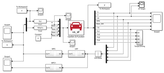
Figure 4.
Overall structure of the simulation platform.
3.2. Simulation Verification of Yaw Stability
In order to verify the effectiveness of the yaw stability control strategy for 4-WID electric vehicles, the model predictive control module and the state parameter estimation module need to be co-simulated. The algorithm is verified by using two commonly used working conditions in automobile handling stability tests, double-lane change and serpentine working conditions.
- (1)
- Simulation of double-lane change test
In order to evaluate the effect of the model predictive control strategy on the yaw stability control of electric vehicles, the ISO3888-2-2002_BS double-lane change international standard test conditions are used. The road condition is a highly adhered road. The model predictive controller predicts time domain Np = 60, control time domain NC = 30, and control period T = 0.05s. The car first accelerates to 60km/h, and then begins the double-lane change performance test. The steering wheel double-lane change input signal is shown in Figure 5a. Simultaneously observe the vehicle’s yaw rate, side slip angle, and the driving torque of each wheel.
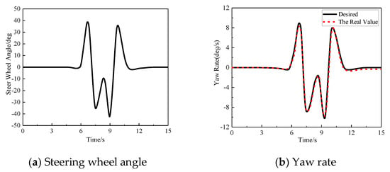
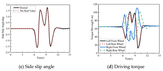
Figure 5.
Simulation of double-lane change test. (a) Steering wheel angle; (b) Yaw rate; (c) Side slip angle; (d) Driving torque.
The simulation result shows that the steering wheel angle is basically zero at the linear acceleration part from the beginning of the simulation, the yaw rate and the side slip angle of the center of mass are unchanged, and the error of the test result can be ignored. When the target speed is reached, the car starts a double-lane change motion test. In the straight driving stage, the driving torque of each wheel is the same. After entering the double-lane change surface, the left and right wheel hub motors provide different driving forces, so that there is a significant torque difference between the left and right wheels. As the steering angle increases, the left and right wheels are distributed. The torque difference obtained is also correspondingly increased to realize the smooth driving of the car during the turning process, thereby ensuring the yaw stability of the car during the course of driving under the double-lane change.
- (2)
- Simulation of snake test
In the serpentine test, the test conditions are GB/T 6323-2014 vehicle handling and stability test conditions, and the steering wheel input is shown in Figure 6a. The target vehicle speed is set to 60 km/h, the initial value of the longitudinal vehicle speed is set to be consistent with the test vehicle speed, and the lateral vehicle speed and yaw rate are set to a small arbitrary value. The road attachment conditions are good.
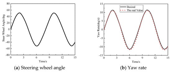
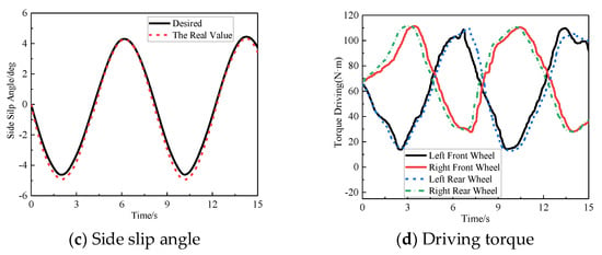
Figure 6.
Simulation of snake test. (a) Steering wheel angle; (b) Yaw rate; (c) Side slip angle; (d) Driving torque.
The simulation results show that the proposed control strategy enables the yaw rate to track the target yaw rate well. Figure 6b shows that the maximum error of the yaw rate is 1.3647°/s and the average error is 0.5041°/s. In Figure 6c, the center of mass slip angle is far below the limit range, the maximum error of the center of the mass slip angle is 0.7334°, and the average error is 0.2966°, indicating that the vehicle driving process is very stable. At the same time, the left and right wheel hub motors provide different driving forces, so that there is a significant torque difference between the left and right wheels, which effectively ensures the steering stability of the vehicle.
3.3. HIL Experiment
In order to verify the accuracy and real-time performance of the state observation algorithm, a hardware-in-the-loop (HIL) platform, based on MicroAutobox, DSP28335, CarSim and Simulink, is used to verify the control strategy. Figure 7 shows the workflow diagram of the HIL platform. The on-board controller (VCU) uses DSP28335. The control strategy built in Simulink is to automatically generate a real-time code to the corresponding VCU, through the RTW real-time code generation environment. Download the real-time code of the vehicle dynamic simulation model set in CarSim to MicroAutobox, and connect it to the VCU I/O port by using the real-time interface (RTI) provided by dSPACE. The experimental platform adopt CAN communication, and the baud rate is set at 500 Kbit/s.
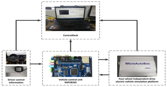
Figure 7.
Schematic diagram of the working process of the HIL platform.
In order to verify the accurate performance of the UKF algorithm, we carry out the steering wheel step input response analysis under the road adhesion coefficient μ = 0.8. The simulation conditions are as follows: the speed is 18 km/h; starting from 1s, the steering wheel rotates 100 at a constant speed and keeps the simulation results as shown in Figure 8.
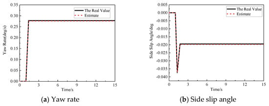
Figure 8.
HIL experiment. (a) Yaw rate; (b) Side slip angle.
According to Figure 8a,b, there is a certain error between the estimated value and the actual value in the initial stage, but, within a short time, the estimated value of the state parameter tends to the true value through the action of the state estimation controller. The estimation error of yaw angular velocity is 0.5 × 10⁻³ °/s, and the standard deviation is 0.47 × 10⁻² °/s. The estimation error of the side slip angle of the centroid is 0.3 × 10⁻³ °/s, and the standard deviation is 0.3 × 10⁻² °/s. The deviation between the estimated value and the true value of both are small and can be ignored.
4. Conclusions
In order to verify the proposed state parameter observation method and yaw stability control method for four-wheel independently driven electric vehicles, a simulation platform was developed, by combining the vehicle model built by CarSim, and the motor model and control strategy built by Matlab/Simulink, and the state parameter estimation strategy and yaw stability control strategy were verified in turn.
- (1)
- Based on the HIL simulation platform of the vehicle state parameter, the estimation algorithm is verified, and the simulation results show that the Kalman estimation algorithm under the steering wheel angle step input yawing angular velocity of the average estimated error was 0.5 × 10⁻³ °/s, the average estimated error of side slip angle was 0.3 × 10⁻³ °, and the simulation result shows that the algorithm can effectively estimate the vehicle state parameter, high estimation precision, and meet the demand of the vehicle online estimate;
- (2)
- With the double-lane change condition and snake conditions for electric vehicles, the yawing motion simulation layer is used to verify. The simulation results show that the maximum errors of yaw velocity are 0.4335 °/s and 1.3647 °/s, respectively, in double-lane change and snaking conditions, which can better track the target value of the yaw rate. The maximum errors of the side slip angle of the center of mass are 0.34°and 0.7334°, respectively. The side slip angle of the center of mass is far below the limit range, which ensures that the vehicle has a sufficient yaw stability margin in the course of steering;
- (3)
- In this paper, the four-wheel-independent-drive electric vehicle state parameter observation and yawing stability study comprehensively improve the real-time stability of the vehicle safety. However, this paper still has some shortcomings. The proposed method can only focus on the influence of the stability of the horizontal pendulum on the state parameters, but ignores the multi-parameter state observation to improve the effect of the yaw stability controller. In addition, in the case of drive skid and drive failure, how to maintain the driving capacity of each wheel to ensure the lateral stability of the vehicle, still needs further research.
Author Contributions
Conceptualization, C.Z. and B.C.; investigation, B.C.; methodology, C.Z. and B.C.; project administration, J.W.; resources, J.W.; software, R.Z., R.W. and J.W.; supervision, C.Z.; validation, C.Z.; writing—original draft, B.C. and R.Z.; writing—review and editing, B.C. and J.W. All authors have read and agreed to the published version of the manuscript.
Funding
This research was funded by the National Natural Science Foundation of China: Research on the Integrated Control Method of the Lateral Stability of Distributed Drive Mining Electric Vehicles (51974229) and the 2021 Youth Innovation Team Construction Scientific Research Program of Shaanxi Provincial Education Department (21JP071).
Institutional Review Board Statement
Not applicable.
Informed Consent Statement
Not applicable.
Data Availability Statement
Not applicable.
Conflicts of Interest
The authors declare no conflict of interest.
References
- Zhou, Y.; Li, S. ABS control algorithm for 4-WID Electric Vehicles. Automot. Eng. 2007, 29, 1046–1050. [Google Scholar]
- BP. BP Statistical Review of World Energy [EB/OL]. Available online: https://www.bp.com/content/dam/bp/business-sites/en/global/corporatepdfs/energy-economics/statistical-review/ (accessed on 6 November 2019).
- Xie, X.; Jin, L.; Jiang, Y.; Guo, B. Research on Integrated Control Method for Handling and Stability of Distributed Electric Vehicle; Jilin University: Changchun, China, 2018. [Google Scholar]
- Chen, Y.; Chen, S.; Zhao, Y.; Gao, Z.; Li, C. Optimized handling stability control strategy for a four in-wheel motor independent-drive electric vehicle. IEEE Access 2019, 7, 17017–17032. [Google Scholar] [CrossRef]
- Ye, G. Research on Direct Yaw Torque Control Strategy of Electric Wheeled Vehicle; Wuhan University of Science and Technology: Wuhan, China, 2018. [Google Scholar]
- Goodarzi, A.; Mohammadi, M. Stability enhancement and fuel economy of the 4-wheel-drive hybrid electric vehicles by optimal tyre force distribution. Veh. Syst. Dyn. 2014, 52, 539–561. [Google Scholar] [CrossRef]
- Eslamian, M.; Alizadeh, G.; Mirzaei, M. Optimization-based non-linear yaw moment control law for stabilizing vehicle lateral dynamics. Proc. Inst. Mech. Eng. Part D J. Automob. Eng. 2007, 221, 1513–1523. [Google Scholar] [CrossRef]
- Zong, C.; Zheng, H.; Tian, C.; Pan, Z.; Dong, Y.; Yuan, D. Vehicle stability based on direct yaw moment control qualitative control strategy. J. Jilin Univ. 2008, 38, 1010–1014. [Google Scholar]
- Li, S.; Guo, K.; Qiu, T.; Wang, G.; Cui, G. Active front wheel steering is stable under extreme. Cond. Automot. Eng. 2020, 42, 191–198. (In Chinese) [Google Scholar]
- Hu, Z. Research on AFS/DYC Cooperative Control Strategy of Distributed Drive Electric Vehicle; Chongqing University: Chongqing, China, 2018. [Google Scholar]
- Wang, Z.; Xue, X.; Wang, Y. Vehicle state parameter estimation based on adaptive untracked kalman filter for distributed drive electric vehicle. J. Beijing Inst. Technol. 2018, 38, 698–702. [Google Scholar]
- Zhao, W.; Zhang, H.; Wang, C. Vehicle state parameter estimation based on untraceless kalman filter. J. South China Univ. Technol. 2016, 4, 76–88. [Google Scholar]
- Bingbing, G.; Gaoge, H.; Shesheng, G.; Yongmin, Z.; Ghengfan, G. Multi–sensor optimal data fusion for INS/GNSS/CNS integration based on unscented Kalman filter. Int. J. Control. Autom. Syst. 2018, 16, 129–140. [Google Scholar]
- Bersani, M.; Vignati, S.; Mentasti, S.; Arrigoni, F.; Cheli, F. Vehicle state estimation based on Kalman filters. In Proceedings of the 2019 AEIT. International Conference of Electrical and Electronic Technologies for Automotive (AEIT AUTOMOTIVE), Turin, Italy, 2–4 July 2019; p. 16. [Google Scholar]
- Mingyang, W.; Jie, J. Laguerre function model predictive control of yaw moment of electric vehicle. J. Chongqing Univ. 2018, 41, 61–69. [Google Scholar]
- Chen, Q. Research on Multi-Model Predictive Control Method for Four-Wheel Independent Drive Electric Vehicle System; Southeast University: Nanjing, China, 2015. [Google Scholar]
- Yu, Z.; Feng, Y.; Xiong, L. Overview of the development status of distributed drive Electric Vehicle dynamics control. J. Mech. Eng. 2013, 49, 105–114. [Google Scholar] [CrossRef]
- Electric Vehicle Resource Network. “1 + 7” Interpretation of the Main Content of “Energy Saving and New Energy Vehicle Technology Roadmap” [EB/OL]. Available online: http://www.evpartner.com/news/8/detail-23214.html (accessed on 26 October 2016).
Publisher’s Note: MDPI stays neutral with regard to jurisdictional claims in published maps and institutional affiliations. |
© 2021 by the authors. Licensee MDPI, Basel, Switzerland. This article is an open access article distributed under the terms and conditions of the Creative Commons Attribution (CC BY) license (https://creativecommons.org/licenses/by/4.0/).