Abstract
The increase in electric vehicles needs to be supported by the existence of reliable energy storage devices. The battery, as an energy storage system, has its advantages and disadvantages. The combination of different battery types is chosen since the battery is one of the energy storage systems with mature technology and low life cycle cost. A solution that can be proposed to cover the weakness of each battery is the use of the Dual Battery System (DBS). In this project, a dual battery control system with a combination of Valve Regulated Lead Acid (VRLA) and Lithium Ferro Phosphate (LFP) batteries was developed using the switching method. Battery selection switching is determined by the specification and operational set point of the battery used. The experimental testing was carried out. The result of the research conducted showed that the current sensor accuracy was 83.75% and the voltage sensor accuracy was 94.25% while the current sensor precision value was 64.91% and the voltage sensor precision was 99.74%. The use of a dual battery system can save energy in a VLRA battery compare with a single VLRA battery by up to 68.62%, whereas in LFP battery by up to 29.48%. This means it gives the advantages of longer distances of traveling in electric vehicles.
1. Introduction
The increase in electric vehicles needs to be supported by the existence of reliable energy storage devices. An example of an energy storage device developed around the world is the battery. The battery is an energy storage device that has functions to convert chemical energy into electrical energy. Many types of batteries are used for electric vehicle applications, such as Lead-acid, NiMH (Nickel-Metal Hydride), Lithium-ion, and Lithium Polymer [1]. In battery usage, many specifications are considered, such as voltage capacity, current capability, battery cycle, mass, specific energy, and temperature sensitivity [2].
Battery, as the energy storage system, has advantages and disadvantages. For example, Valve Regulated Lead Acid (VRLA) batteries can withstand the starting current conditions and are resistant to overcharging [2]. VRLA batteries have limited capabilities in carrying out functions such as large internal resistance of the battery, which affects the rapid voltage drop or self-discharge and the possibility of damage to high loads. Meanwhile, Lithium Ferro Phosphate (LFP) batteries are the most popular type of rechargeable battery because they have a very good energy density, without memory effect, and experience slow self-discharge when not used [3]. The LFP battery has a maximum and minimum voltage limit which if it exceeds the voltage limit it can cause damage to the battery [4].
Hybrid Energy Storage Systems (HESS) is developed in the utilization of two or more different storage devices. According to [5] combining multiple energy storage systems can provide improvements in performance, cost, mass, volume, and efficiency. The goal of using battery hybridization is to combine the advantages and eliminate the disadvantages of each other’s [6]. There are many energy storage hybridizations, for example, battery and supercapacitor [7,8], battery and fuel cell [9], etc. The combination of different battery types is chosen since the battery is one of the energy storage systems with mature technology and low life cycle cost [10]. A solution that can be proposed to cover the weakness of each battery is the use of the Dual Battery System (DBS) [11].
There is some researcher that combines two types of batteries in electric vehicles. Rizzo, D., et al. [5] propose the combination between lithium-ion (Li-ion) and lithium-silicon (Li-Si) in the simulation environment. They propose two topologies that are using two DC-DC converters for each battery and the other topology is using only one DC-DC converter for Li-Si. They conclude that Li-Si cells are advantageous since it has a lower mass per unity. Besides that, the use of two DC-DC converters gives more flexibility in battery voltage which can reduce total HESS cost. Ahmadkhanlou, et al. [12] propose DBS in plug-in hybrid electric vehicles. They compare single battery and dual battery using a DC-DC converter in the simulation environment. They use two types of batteries namely high energy and ultra-high power. The result is two battery systems can increase efficiency by up to 18%. Chung and Trescases [13] propose HESS by combining lithium-ion (Li-ion) and lead-acid (PbA) batteries for Light Electric Vehicles. The proposed system using multiple converters to actively manage power flow between the two batteries. They conclude that compared to a single lead-acid battery, the HESS system can achieve a 23% efficiency improvement and 17% range improvement, whereas Vishnu and Ajaykrish [14] proposed a combination of dual batteries to optimize energy utilization. The NiMH battery used for steady speed driving and lead-acid used for vehicle starting. They conclude that the proposed system reduces CO2 emission by about 40–50%.
In this project, a VRLA and LFP dual battery system is proposed, including switching between the two batteries and monitoring. In this case, the technique used is the soft switching technique between the two batteries in providing power to the load without a DC-DC converter. The soft-switching technique aims to provide a smooth transition when used in electric vehicles. The battery switching system that supplies the load is adjusted to variations in the load and battery operation. The monitoring feature functions to see the condition of the battery capacity, battery pack temperature, current, voltage, and power supplied by the battery to the load. The design of the switching system with a dual battery platform is expected to be able to distribute the load requirements according to the appropriate battery operation.
2. Materials and Methods
2.1. Valve Regulated Lead Acid (VRLA) Battery
VRLA batteries are one type of battery that uses lead-acid as its chemical. VLRA batteries become popular for powering Electric Vehicle (EV) because of its high specific power, low initial cost, and quick charge capability, and no maintenance requirement [15]. VRLA batteries can cope with load variations quickly but are susceptible to high loads for long periods. The type of lead-acid battery used in this project is the Panasonic LC-R127R2PG1 with a nominal voltage of 12 V and a current capacity of 7.2 Ah. Figure 1a shows an example of a VLRA battery.
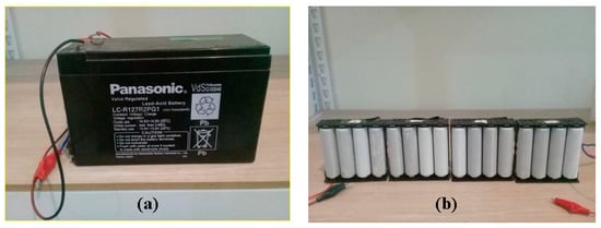
Figure 1.
(a) VRLA battery; (b) LFP battery.
2.2. Lithium Ferro Phosphate (LFP) Battery
Batteries with lithium-based technology include batteries that have a high specific energy and cycle life among other batteries and are widely applied in electric vehicles [3]. Lithium batteries are generally applied to electric vehicles as either a primary energy source or a secondary energy source. However, in its application, the use of lithium-ion batteries requires protection according to their operational characteristics which are sensitive to charging, discharging, and temperature changes [16,17]. The following are the types of cathode materials in lithium batteries, such as Lithium Cobalt Oxide (LiCoO2), Lithium Manganese Oxide (LiMn2O4), Lithium Iron Phosphate (LiFePO4), Lithium Nickel-Manganese Cobalt Oxide (LiNiMnCoO2), Lithium Nickel Cobalt Aluminum Oxide (LiNiCoAlO2), and Lithium Titanate (Li4Ti5O12) [18]. In this project, the type of Lithium Ferro Phosphate (LFP) battery produced by UNS Business Development Center (PUSBANGNIS UNS) is used. LFP batteries are made of nano-scale phosphate material so that they have low resistance, long battery life, high load handling ability, safety when the temperature is high compared to other types of lithium, have no toxic/toxic effects, and lower costs. LFP has a sensitivity to a temperature where there are some operational decreases due to the influence of temperature. An example of an LFP Cell battery is depicted in Figure 1b.
2.3. Specifications and Operational of VRLA and LFP Batteries
The collection of specification data was carried out to determine the product operation of the batteries used. In this study, the collection of specifications of the VRLA battery type LC-R127R2PG1 and LFP pack batteries are listed in Table 1. Known some critical limits of a battery used is important in determining battery switching. Parameters from the sensor readings and load variations will be adjusted to the operation of the battery product used.

Table 1.
Critical limits of Dual Battery Valve Regulated Lead Acid (VRLA) and Lithium Ferro Phosphate (LFP) [19,20,21].
2.4. Battery Sensor
2.4.1. Voltage Sensor
The voltage sensor is made with a voltage divider to find the value of the battery voltage. The reading of the battery voltage is known to be linear to the SOC (State of Charge) value so that the voltage value of a battery can be written and modeled in an equation function of the SOC [22]. This sensor reading is used as feedback in the dual battery switching system. The voltage sensor circuit of each battery is depicted in Figure 2.
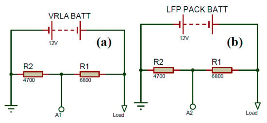
Figure 2.
Voltage sensor at each battery (a) VRLA battery; (b) LFP battery.
2.4.2. Current Sensor
The current sensor used is an ACS712 current sensor module with a sensitivity of 66 mV/A. The ACS712 current sensor is capable of measuring currents from −30 A to 30 A. Any current that passes through the sensor will affect its output operating voltage. The current reading is used to monitor current consumption and to detect which battery is connected to the load. This sensor is only used in simulation mode. The current sensor circuit is depicted in Figure 3.
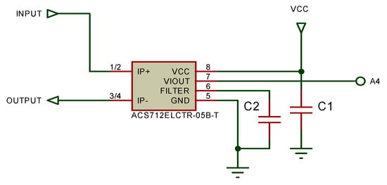
Figure 3.
Current sensor circuit.
2.4.3. Temperature Sensor
The temperature sensor used is a DS18b20 temperature sensor module. Sensor readings are used as feedback in the dual battery switching system. The temperature value that the sensor reads will be compared with the battery temperature limit and the result will affect the battery selection. The temperature sensor circuit is depicted in Figure 4.
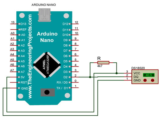
Figure 4.
Temperature sensor circuit.
2.5. Load Sensor
The voltage and current sensor used to monitor the power consumed by the load. The voltage sensor used is a voltage divider circuit. This voltage sensor aims to read the value of the voltage consumption at the load based on operational variations. The load voltage sensor circuit is shown in Figure 5, whereas the current sensor is the same as shown in Figure 3.
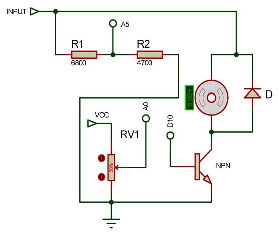
Figure 5.
Voltage sensor circuit at load.
2.6. Switching System
The switching system includes the power MOSFET as a switching component and IR2101 as the MOSFET driver. The use of MOSFET because it is a power switch controlled by voltage [23]. The arrangement of the MOSFET uses a PWM signal to provide a smooth opening and closing transition of the MOSFET. The MOSFET circuit and its gate driver is depicted in Figure 6. There is a MOSFETs connected to each battery. When the VLRA battery is selected, the MOSFET connected to it is ON and MOSFET to the LFP is switched OFF, and vice versa.
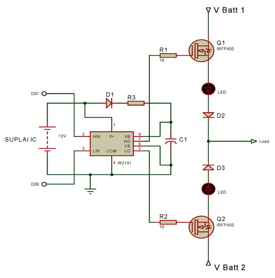
Figure 6.
Switching circuit.
2.7. Whole System Design
The result of this research is a prototype, so it is necessary to model the system according to a simple electric vehicle system. Figure 7 is a block diagram of a simple electric vehicle system including a power supply, control system, and drive system. In this project, the power supply used is a dual battery that is a VRLA battery and an LFP battery. The control system used is the Arduino and the L298n motor driver to replace the electric vehicle control system. In the drive system using a DC motor with a rated voltage and current of 12 V and 0.18 A, respectively. There is a sensor on the battery side and the load. The data from the sensor are used in the switching algorithm to determine which battery will be used.
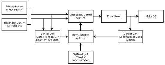
Figure 7.
Block diagram of a simple electric vehicle with dual battery system.
The flow process of switching between two batteries can be seen in Figure 8. Starting when the system is turned on, the primary battery (VLRA) is connected to the system. Then, the potentiometer, as a throttle, is varied to control the load. Sensor data are sent to the Arduino to determine the switching between two batteries. There are three conditions that determine to switch, which are battery temperature, battery voltage, and potentiometer position, with battery temperature as the first priority and potentiometer as last priority. If the potentiometer is greater than the reference, then the switching system activates the LFP battery. The voltage sensor senses battery voltage when the battery voltage over the battery minimum references the switch change to the other battery. The reference values for a potentiometer, battery voltage and battery temperature can be seen in Table 2.
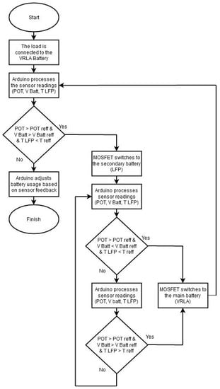
Figure 8.
Flowchart of switching algorithm between two batteries.

Table 2.
Critical limits of Dual Battery VRLA and LFP.
3. Results and Discussion
This chapter describes the results of the testing as a whole project, both the simulation and experiment will be presented.
3.1. Simulation Testing
In this test, the simulation is run by changing the potentiometer value to see whether the results match the algorithm that has been designed. Switching scenario based on the potentiometer value, if the potentiometer value is <50%, the battery is connected to VRLA, and if the potentiometer value is >50%, the battery is connected to LFP. In this simulation, the potentiometer value is 60% and the LFP battery is connected to the load as depicted in Figure 9.
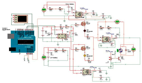
Figure 9.
Simulation circuit run with potentiometer value of 60%.
Switching wave testing is carried out to test whether the circuit is working or not. Testing of the switching wave on MOSFET is taken from the virtual oscilloscope. When switching occurs, the PWM value of the high output connected to the MOSFET gate will change from 255 to 0, produce in a soft-switching wave. The result of the switching wave on MOSFET connected to the LFP battery when the PWM value is 60% is depicted in Figure 10.
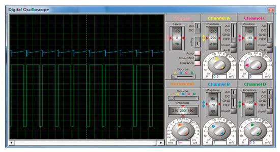
Figure 10.
Switching wave of simulation from virtual oscilloscope.
3.2. Hardware Testing
In hardware testing, several tests were carried out, namely testing the sensor accuracy and sensor precision, testing single VRLA and LFP batteries, and testing multiple batteries. A circuit board after assembly and packaging is shown in Figure 11. The whole hardware system simulation includes a dual battery control system, motor driver, potentiometer, and the motor are depicted in Figure 12.
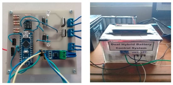
Figure 11.
Dual battery control system.
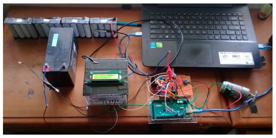
Figure 12.
Overall system hardware.
3.2.1. Sensor Accuracy and Precision
Accuracy testing is carried out to determine the amount of error value and the accuracy of the current and voltage sensor. Accuracy testing is done by varying the potentiometer opening from 10% to 100% (there are 10 variations of the experiment) by comparing the sensor value with the measurement value of the measuring instrument. Comparison of the current measurement value and the current reading value is depicted in Figure 13a and the error change value is shown in Figure 13b. The accuracy of the current sensor is 83.75%.
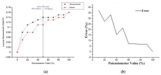
Figure 13.
Graph of current sensor: (a) Current value reading; (b) Error value.
As seen in Figure 13a, a high spike occurs when the potentiometer opening is from 0–10%. The current sensor reading value has an unstable increase which is influenced by the sensitivity of the sensor and the small value of the current consumed by the load. Whereas in Figure 14, the value of the voltage change has increased regularly, where the greater the value of the potentiometer, the load consumption voltage is getting bigger. The accuracy of this voltage sensor is 94.25%.
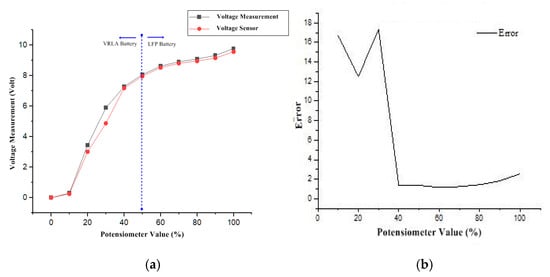
Figure 14.
Graph of voltage sensor: (a) Voltage value reading; (b) Error value.
Precision testing aims to find out how close the reading value is when testing several times. Precision testing is carried out by making repeated sensor readings 25 times under the same conditions (same load). The current sensor testing precision value is depicted in Figure 15a and the voltage sensor testing precision value is depicted in Figure 15b. The precision of the current sensor and voltage sensor is 64.91% and 99.74%, respectively.
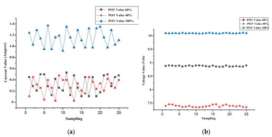
Figure 15.
Precision Testing of hardware: (a) Current sensor precision testing; (b) Voltage sensor precision testing.
3.2.2. Single Battery
A single battery testing is performed to determine the amount of voltage, current, power, and energy consumption when using only one battery. This test will be compared with the use of dual batteries so that the optimization can be determined. Single battery testing is done by varying the load, from the potentiometer value 0% to 60%, then to 40%, then to 100%, and back to 0%.
Figure 16 shows the current reading, the maximum current (Imax) consumed by the load at 100% potentiometer opening is 0.86 A and 0.82 A for VRLA and LFP battery, respectively. The voltage result of this test is shown in Figure 17. It clearly is seen that the voltage variation is linear with a potentiometer opening. The reading of the VRLA battery voltage consumption has a Vmax of 10.34 V when the potentiometer is 100% open, while the reading of the LFP battery voltage consumption has a Vmax of 10.18 V when the potentiometer is 100% open. The power value is depicted in Figure 18. The maximum power of the VLRA dan LFP battery is 8.868 W and 8.682 W, respectively.
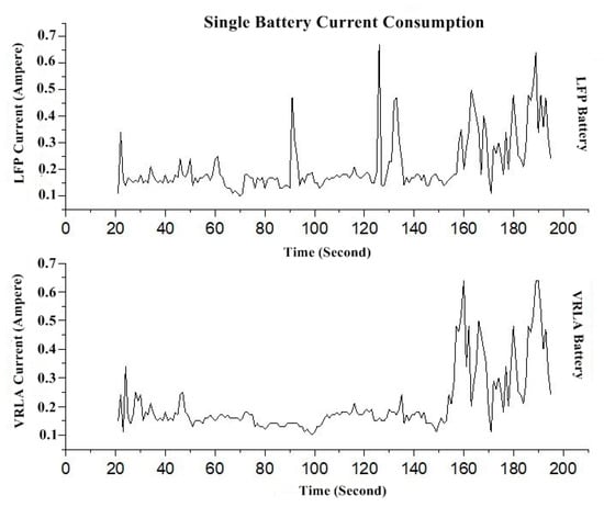
Figure 16.
Single battery current consumption of VRLA and LFP graph.
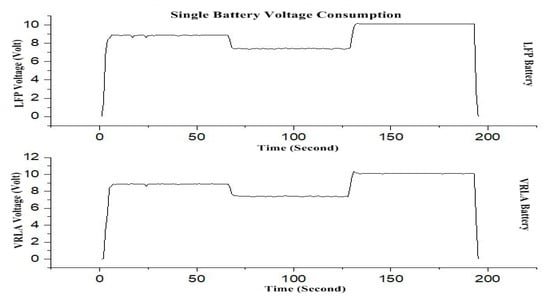
Figure 17.
Single battery voltage consumption of VRLA and LFP graph.
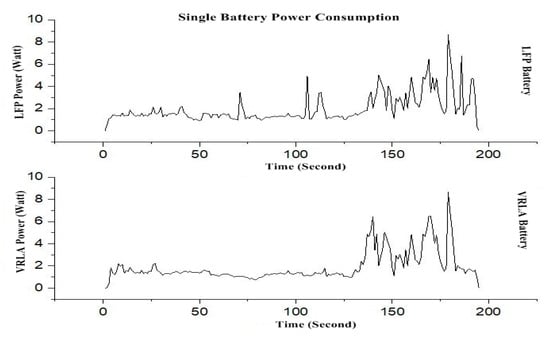
Figure 18.
Single battery power consumption of VRLA and LFP graph.
3.2.3. Dual Battery
The dual hybrid battery test is carried out by observing the current, voltage and power consumption of the battery usage. The dual battery control system has a role in determining the battery selection according to load variations and load conditions. In this test, the load variation from the potentiometer opening is the same as single battery testing. In the switching scenario where the potentiometer opening 0% to 50%, the load will be connected to the VRLA battery and when 51% to 100%, the load connected to the LFP battery.
Figure 19 shows the current consumption of dual battery system testing. It can be seen in the graph that the Imax value of 0.68 A is charged to the LFP battery and for system average of 0.225 A is charged to the VRLA battery. Figure 20 shows the value of voltage consumption on dual batteries. As can be seen in the graph, the voltage consumed is adjusted by the battery switching scenario so that the battery is still used only in certain circumstances. The system Vmax of 10.18 V is charged to the LFP battery and the average of 8.61 V is charged to the VRLA battery.
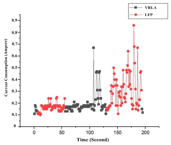
Figure 19.
Dual battery current consumption of VRLA and LFP graph.
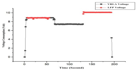
Figure 20.
Dual battery voltage consumption of VRLA and LFP graph.
Figure 21 shows the power value of the dual battery system. It can be seen that the distribution of power absorption is carried out on dual batteries according to the switching scenario, if the potentiometer value is <50%, the load charged to the VRLA battery, and if the potentiometer value is >50% load charged to the LFP battery with details of Pmax is 6.681 W on the LFP battery and 2.003 W on the VRLA battery.
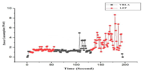
Figure 21.
Dual battery power consumption of VRLA and LFP graph.
Testing of switching waves was carried out using Oscilloscope Hantek 6022BE Version 1.0.6 through the Hantek software on a laptop by looking at the PWM waves from Arduino’s high output and switching on the MOSFET pin source. As seen in Figure 22, a wave is formed when the PWM input value is 80% on the high output side. The wave has a time/div of 2 ms and 5 V volt/div. The period value of the PWM wave is 6 ms and the amplitude value is 20 V.
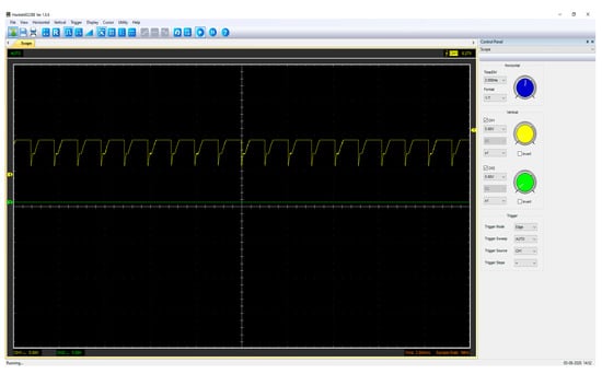
Figure 22.
Switching wave on MOSFET Source when transitioning.
Optimization testing is carried out by comparing the use of load on a single battery and dual batteries as well as current consumption, power, and voltage on battery operations. Table 3 shown the energy usage for a dual battery and a single battery. The value of the power is calculated based on the value that the sensor reads every second based on (1). The result of the energy value is obtained from the power value multiplied by time, as in (2). From the results of the energy calculation for each second of the sensor readings, all the energy values for each second of the sensor readings are added up until the total value of energy consumption is obtained.
P = v × i
E = P × t

Table 3.
Energy consumption of battery.
Figure 23 shows the distribution of energy use in dual batteries. It can be seen that after testing the load variation, the VRLA battery energy consumption value is 117, 20 Joule, and the LFP energy consumption value is 273.48 Joule with the percentage of use when testing is 30% VRLA battery and 70% LFP battery. In the use of dual batteries, the load on one battery can be divided based on the switching scenario that is carried out.
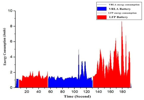
Figure 23.
Percentage of energy used of dual battery.
Figure 24 is the energy consumed by each battery. It can be seen that the distribution of energy use is adjusted to the switching scenario. From the results of using dual battery system, the saving value of each battery can be calculated by comparing the value of a single battery and a dual battery. Table 4 shows the percentage value of a dual battery energy saving when compared to single battery model. The use of VRLA batteries can save up to 68.62% of energy consumption compared to full use of a single VRLA battery and the use of LFP batteries can save up to 29.48% energy consumption compared to full use of a single LFP battery.
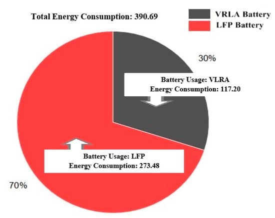
Figure 24.
Energy consumption graph in dual hybrid battery testing.

Table 4.
Comparison of battery energy use and energy savings.
4. Conclusions
A dual battery control system of valve-regulated lead-acid (VRLA) and lithium ferro phosphate (LFP) has been designed using a switching technique. The switching method is determined based on the operation of the battery used. The two batteries are working independently based on the activation from the switching algorithm. The experimental testing was carried out. The result shows that a dual battery system can work well. In the experimental test, it is shown that the proposed system consumed more energy. This means, if used in hybrid vehicles it will save more fuel. The use of a dual battery system can save energy in a VLRA battery compare with a single VLRA battery by up to 68.62%, whereas in LFP battery by up to 29.48%. This means it gives the advantages of longer distances of traveling in the electric vehicle. The proposed dual battery system also gives another advantage in vehicle mass and battery price, since VLRA has high mass with low price, while LFP is vice versa. Therefore, combining it will give lower mass and battery prices compare with the use of a single battery system.
Author Contributions
Conceptualization, M.N. and H.M.; methodology, M.N.; validation and analysis, H.M. and F.N.K.; investigation and data collection, F.N.K.; writing—original draft preparation, H.M. and F.N.K.; writing—review and editing, F.A. All authors have read and agreed to the published version of the manuscript.
Funding
This research activity is supported through funding from the Ministry of Research and Technology/the National Research and Innovation Agency through RISPRO Funding with contract number 86/E1/PRN/2020.
Conflicts of Interest
The authors declare no conflict of interest.
References
- Un-noor, F.; Padmanaban, S.; Mihet-popa, L. A comprehensive study of key electric vehicle (EV) components, technologies, challenges, impacts, and future direction of development. Energies 2017, 10, 1217. [Google Scholar] [CrossRef]
- Afif, M.T.; Ayu, I.; Pratiwi, P. Comparative analysis of lithium-ion, lithium-polymer, lead acid and nickel-metal hydride batteries in electric car use-review (in Bahasa). J. Rekayasa Mesin 2015, 6, 95–99. [Google Scholar] [CrossRef]
- Tie, S.F.; Wei, C. A review of energy sources and energy management system in electric vehicles. Renew. Sustain. Energy Rev. 2013, 20, 82–102. [Google Scholar] [CrossRef]
- Venkatasetty, H.V.; Jeong, Y. Recent advances in lithium-ion and lithium-polymer batteries. In Proceedings of the Seventeenth Annual Battery Conference on Applications and Advances, Long Beach, CA, USA, 18 January 2002; pp. 173–178. [Google Scholar]
- Riczu, C.; Habibi, S.; Bauman, J. Design and optimization of an electric vehicle with two battery cell chemistries. In Proceedings of the 2018 IEEE Transportation Electrification Conference and Expo (ITEC), Long Beach, CA, USA, 13–15 June 2018; pp. 506–512. [Google Scholar]
- Jamahori, H.F.; Rahman, H.A. Hybrid energy storage system for life cycle improvement. In Proceedings of the 2017 IEEE Conference on Energy Conversion (CENCON), Kuala Lumpur, Malaysia, 30–31 October 2017; pp. 196–200. [Google Scholar]
- Vidhya, S.D.; Balaji, M. Modelling, design and control of a light electric vehicle with hybrid energy storage system for Indian driving cycle. Meas. Control 2019, 52, 1420–1433. [Google Scholar] [CrossRef]
- Trovão, J.P.F.; Santos, V.D.N.; Pereirinha, P.G.; Jorge, H.M.; Antunes, C.H. A simulated annealing approach for optimal power source management in a small EV. IEEE Trans. Sustain. Energy 2013, 4, 867–876. [Google Scholar] [CrossRef]
- Thounthong, P.; Chunkag, V.; Sethakul, P.; Davat, B.; Hinaje, M. Comparative study of fuel-cell vehicle hybridization with battery or supercapacitor storage device. IEEE Trans. Veh. Technol. 2009, 58, 3892–3904. [Google Scholar] [CrossRef]
- Ronanki, D.; Member, S.; Singh, S.A.; Member, S.; Williamson, S.S.; Member, S. Comprehensive topological overview of rolling stock architectures and recent trends in electric. IEEE Trans. Transp. Electrif. 2017, 7782, 1–15. [Google Scholar]
- Renner, D.; Dietz, M.; Jansen, P.; Vergossen, D.; John, W.; Frei, S. Predictive power estimation of dual battery systems in mild-hybrid vehicles. In Proceedings of the IEEE Vehicle Power and Propulsion Conference (VPPC), Hangzhou, China, 17–20 October 2016. [Google Scholar]
- Ahmadkhanlou, F.; Goodarzi, A.; Kang, D. Plug-In hybrid electric vehicle with dual battery system. In Proceedings of the 25th World Battery, Hybrid, and Fuel Cell Electric Vehicle Symposium dan Excibiton, Shenzhen, China, 5–9 November 2010; pp. 7–10. [Google Scholar]
- Chung, S.; Trescases, O.; Member, S. Hybrid energy storage system with active power-mix control in a dual-chemistry battery pack for light electric vehicles. IEEE Trans. Transp. Electrif. 2017, 3, 600–617. [Google Scholar] [CrossRef]
- Vishnu, P.; Ajaykrishna, R.; Thirumalini, S. Cost effective energy solution with dual battery for plug-in hybrid electric vehicle (phev) in a public transportation system. In Proceedings of the 7th IEEE Conference on Industrial Electronics and Applications (ICIEA), Singapore, Singapore, 18–20 July 2012; pp. 1555–1560. [Google Scholar]
- Hannan, M.A.; Hoque, M.M.; Mohamed, A.; Ayob, A. Review of energy storage systems for electric vehicle applications: Issues and challenges. Renew. Sustain. Energy Rev. 2017, 69, 771–789. [Google Scholar] [CrossRef]
- Vazquez, S.; Lukic, S.M.; Galvan, E.; Franquelo, L.G.; Carrasco, J.M. Energy storage systems for transport and grid applications. IEEE Trans. Ind. Electron. 2010, 57, 3881–3895. [Google Scholar] [CrossRef]
- Hoque, M.M.; Hannan, M.A.; Mohamed, A. Voltage equalization control algorithm for monitoring and balancing of series connected lithium-ion battery. J. Renew. Sustain. Energy 2016, 8. [Google Scholar] [CrossRef]
- Chau, K.T.; Wong, Y.S.; Chan, C.C. An overview of energy sources for electric vehicles. Energy Convert. Manag. 1999, 40, 1021–1039. [Google Scholar] [CrossRef]
- VRLA. Technical Handbook Industrial Batteries for Professionals; Panasonic: Hamburg, Germany, 2017. [Google Scholar]
- liFePo4 18650 Cylindrical Battery Specification; AA Portable Power Corp: Richmond, VA, USA, 2006.
- Hua, Y.; Xu, M.; Li, M.; Ma, C.; Zhao, C. Estimation of state of charge for two types of lithium-ion batteries by nonlinear predictive filter for electric vehicles. Energies 2015, 8, 3556–3577. [Google Scholar] [CrossRef]
- Udin, M.; Sri Kaloko, B.; Hardianto, T. Prediction capacity of lead acid battery on electric vehicle based neural network levenberg (in Bahasa). Berk. Sainstek 2017, 5, 112. [Google Scholar] [CrossRef][Green Version]
- Nizam, M.; Maghfiroh, H.; Rosadi, R.A.; Kusumaputri, K.D.U. Design of battery management system (BMS) for lithium iron phosphate (LFP) Battery. In Proceedings of the 6th International Conference on Electric Vehicular Technology (ICEVT), Bali, Indonesia, 18–21 November 2019; pp. 170–174. [Google Scholar]
Publisher’s Note: MDPI stays neutral with regard to jurisdictional claims in published maps and institutional affiliations. |
© 2021 by the authors. Licensee MDPI, Basel, Switzerland. This article is an open access article distributed under the terms and conditions of the Creative Commons Attribution (CC BY) license (http://creativecommons.org/licenses/by/4.0/).