Article

Multi-Phase Fractional-Slot PM Synchronous Machines with Enhanced Open-Circuit Fault-Tolerance: Viable Candidates for Automotive Applications

Research Laboratory on Renewable Energies and Electric Vehicles, University of Sfax, ENIS, P.O. Box 1173, Sfax 3038, Tunisia
*
Author to whom correspondence should be addressed.
World Electr. Veh. J. 2021, 12(1), 32; https://doi.org/10.3390/wevj12010032
Submission received: 1 January 2021 / Revised: 21 January 2021 / Accepted: 12 February 2021 / Published: 20 February 2021
(This article belongs to the Special Issue Novel Permanent Magnet Machines and Drives for Electric Vehicles)

Abstract

:
This paper deals with the winding arrangement of multi-phase fractional-slot permanent magnet (PM) synchronous machines (FSPMSMs), with emphasis on the enhancement of their open-circuit fault-tolerance capability. FSPMSMs are reputed by their attractive intrinsic fault-tolerance capability, which increases with the number of phases. Of particular interest is the open-circuit fault-tolerance capability, which could be significantly enhanced through the parallel connection of the coils or suitable combinations of the coils of each phase. Nevertheless, such an arrangement of the armature winding is applicable to a limited set of slot-pole combinations. The present work proposes a design approach that extends the slot-pole combinations to candidates that are characterized by a star of slots including three phasors per phase and per winding period. It has the merit of improving the tolerance against open-circuit faults along with an increase in the winding factor of multi-phase machines. Special attention is paid to characterization of the coil asymmetry required for the phase parallel arrangement. A case study, aimed at a finite element analysis (FEA)-based investigation of the open-circuit fault-tolerance of a five-phase FSPMSM, is treated in order to validate the analytical prediction.

1. Introduction

Much attention is currently given to multi-phase ac machines to equip several applications covering a variety of drives and generators. Among the major motivations behind this trend, one can distinguish the high fault-tolerance capability, which is a vital requirement in mobility applications starting from aerospace to automotive systems. Permanent magnet synchronous machines (PMSMs) are viable candidates to equip multi-phase drives integrated in automotive applications. Of particular interest are fractional-slot PMSMs (FSPMSMs), which are reputed by their intrinsic high fault-tolerance capability. Basically, these machines are characterized by a very weak magnetic coupling between the armature phases [1]. Consequently, a faulty phase does not affect the operation of the healthy ones.
Thanks to their modularity, FSPMSMs are suitably adapted to multi-phase designs that have a direct impact on the improvement of their fault-tolerance capability. An approach to improve the fault-tolerance of FSPMSMs was proposed in [2]. It consists of connecting in parallel the coils or suitable combinations of coils of each phase, such that, in case of an open-circuit fault, only the concerned branch rather than the total phase in the case of series-connected coils becomes passive. Furthermore, with their phases arranged in parallel branches, the FSPMSMs become suitably adapted for low-voltage power supplies that make them viable candidates for possible integration in 42 V automotive technology. This potentiality is by far vital in battery electric vehicles, where passenger safety is significantly improved in the case of accidents, with the risk of electrocution completely discarded thanks to the reduction in DC bus voltage.
The design of multi-phase FSPMSMs has been widely reported in the literature. The most recent works are reviewed hereunder. In [3], Gu et al. developed an approach to analytically predict optimal and critical ratios for the third harmonic current injection in five-phase FSPMSMs in so far as it leads to an improvement in the torque production capability. It has been found that the optimal and critical injection ratios along with the torque improvement are dependent on the ratio of the third harmonic back electromotive force to the fundamental one. In order to improve the third harmonic contribution to the torque production, unequal tooth was considered with its optimal value, as been demonstrated by FEA. In [4], Zhang et al. considered the design of two fault-tolerant FSPMSMs with interior PMs in the rotor and open-end winding in the stator equipped with three and five phases. It has been found that the five-phase machine exhibits less processing cost, smaller torque ripples, higher power density, better flux-weakening capability, better fault-tolerance, and more design degrees of freedom, making it a viable candidate for automotive and aerospace applications. In [5], Gong et al. considered the design of double polarity five-phase FSPMSMs, developing the same torque either by first or third current harmonic. Beyond their intrinsic fault-tolerance capability, the designed bi-harmonic FSPMSMs offer further degrees of freedom to optimize their voltage supply and to consequently improve their flux-weakening control performance. The features of the proposed concepts have been compared with those of three-phase machines. In [6], Wu et al. proposed an SiC-based integrated modular motor drive built around a five-phase FSPMSM. The converter directly connected to the end-turn of the motor armature phases to reduce the wiring cable losses. The motor and converter were cooled by a water jacket, which significantly reduced the weight of the drive and improved the power density. A thermal analysis of the motor was achieved in order to improve the reliability of the system at high-temperature operation. In [7], Scuiller et al. considered the design and control of a seven-phase FSPMSM characterized by two fundamental harmonics. The so-called bi-harmonic design specificity was considered in order to achieve a high torque production capability. The magnet layer was segmented into two identical radially magnetized tiles that covered about three-quarters of the pole arc. Regarding the control aspect, the maximum torque per Ampere strategy was implemented considering a third harmonic current component greater than the fundamental one.
Beyond the design of multi-phase FSPMSMs, several dedicated control strategies were proposed for post-fault operations in an attempt to recover the torque production capability and to reduce losses and noise. In [8], Zhou et al. proposed a control strategy based on a voltage feed-forward compensation approach dedicated to five-phase external rotor FSPMSMs under short-circuit fault. This was performed to minimize pulsating torque and to improve dynamic performance. The effect of the short-circuit fault on the FSPMSM model expressed in the rotating synchronous frame was discussed. It has been found that the proposed strategy enables a reduction in the torque ripple with an improvement in the drive dynamic under faulty operation. In [9], Zhang et al. introduced a fault-tolerant direct torque control strategy dedicated to five phase FSPMSMs with interior PMs. The proposed strategy was based on the emulation of the operation of three-phase space vector pulse width modulation. The reliability of the drive was proven under an open-circuit fault. It has been demonstrated that, under the control of the proposed strategy, the drive exhibited appreciable dynamic performance under faulty scenarios. In [10], Wang et al. treated the injection of the third harmonic into the phase current waveforms in an attempt to improve the torque production capability of five-phase interior permanent magnet (PM) machines. The third harmonic current was optimally derived under the constraints of similar peak and rms values as in the case of a pure sinusoidal current supply. A design approach based on unequal tooth/PM segmentation was considered in order to improve the third harmonic back-EMFs. In [11], Cui et al. synthesized an unequal zero-voltage vector modulation strategy for a five-phase open-winding fault-tolerant FSPMSM with interior PMs. The proposed strategy enabled the suppression of the zero sequence current caused by the dead-time. A zero-axis controller was designed, yielding the reference common-mode voltage. In [12], Fan et al. proposed a torque ripple minimization control strategy for inter-turn short-circuit fault dedicated to five-phase fractional slot-concentrated winding interior permanent magnet motor drive. An approach to eliminate the influence of the short-circuit loop current was developed considering a feed-forward compensator. It has been shown that this latter can be estimated in real-time using the zero-sequence voltage and zero-sequence current. In [13], Chen et al. proposed a unified decoupling vector control strategy intended to minimize the torque ripple and to improve the dynamic performance for a five-phase PM motor under a double-phase open-circuit or short-circuit faulty scenario. The five-phase FSPMSM under study has an inverted topology (inner stator and outer rotor) equipped with 20 single-layer slots and 22 V-shaped poles.
Muli-phase FSPMSMs with aneven number of phases were also reported in the literature. In [14], Liu and Zhu introduced the magnetic gearing effect and the gear ratio in FSMPSMs, considering different number of phases and slot-pole combinations. It has been found that the gear ratio can provide a unified reference for FSMPSMs of different numbers of phases to evaluate performance and to select suitable slot–pole combinations. The influence of the gear ratio on the winding factor, the output and cogging torques, the inductance, and the rotor loss of 3- and 6-phase FSPMSMs was analyzed and validated by experiments. In [15], Zhang et al. considered the selection of the pole–slot combination and winding arrangement of a twelve-phase fractional-slot concentrated winding permanent magnet (PM) motor dedicated to ship propulsion. The constraint conditions of the pole–slot combination with different winding combination modes were analyzed. The effects of different slot–pole combinations and winding arrangements on the winding factor and the vibration caused by radial magnetic forces and torque ripple were investigated. In [16], Harke treated in detail the arrangement of six-phase FSPMSMs. The possible slot–pole combinations were discussed. Based on the star of slots approach, two winding arrangement techniques were compared. The fault tolerance capability enabled highlighting the superiority of the design with two six phase belts. In [17], Liang et al. treated the post-fault decoupling modeling and field-oriented control strategy dedicated to a dual three-phase surface-mounted permanent magnet synchronous machine with isolated neutrals under single-phase open-circuit fault. Post-fault current references were reconfigured along with a loss minimization and torque maximization. Furthermore, the third harmonic flux linkage/back-EMF were taken into account as far as the resulting third harmonic currents causing significant torque ripple under single-phase open-circuit fault.
The present work extends the approach proposed in [
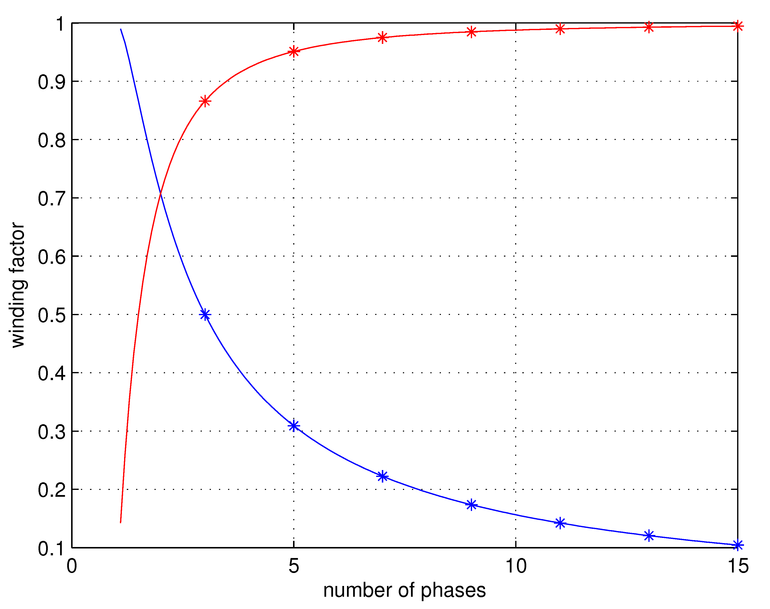
2] to a class of FSPMSMs with their armature winding characterized by a star of slots including three phasors per phase and per winding period. These make parallel arrangement of their phases considering asymmetric coils possible. This enables an improvement in their open-circuit fault-tolerance as well as their winding factor. It is shown that these performance increase with the number of phases.

2. Arranging FSPMSM Phases According to Parallel Branches

The approach proposed in [2] is suitably adopted to improve the open-circuit fault-tolerance of FSPMSMs, especially when the phase parallel branches include only one coil each. Considering an odd number of phases wound in double-layer slots, these machines are characterized by a star of slots where the back-EMF phasors of a given phase are colinear:
  • completely located in one sector, as illustrated in Figure 1, and
  • equally distributed in the two opposite sectors assigned to the phase, as shown in Figure 2.
The connection of the coils of a phase in both cases is depicted in Figure 3.
The case where the phasors of the back-EMFs induced in the coils of a given phase are colinearly equally distributed in the two opposite sectors is useless for multi-phase machines as far as it leads to a winding factor that decreases with an increase in the number of phases q, such that
K w = sin π 2 q
While in the case where the phasors of the back-EMFs induced in the coils of a given phase are colinearly aligned in one sector, the winding factor increases with an increase in q, as follows:
K w = cos π 2 q
Figure 4 gives the variation of the winding factor with respect to the number of phases in both cases.

2.1. Case of Three Slots Per Phase and Per Winding Period

2.1.1. Principle of Arranging the Phases in Parallel Branches

This section considers a combination of the two classes of FSPMSMs identified previously. It has the merit of improving tolerance against open-circuit faults along with an increase in the winding factor. The targeted candidates are characterized by a star of slots where the phasors corresponding to the back-EMFs induced in the coils of a given phase are asymmetrically distributed in the two opposite sectors assigned to the phase. More specifically, they are considered the candidates characterized by a star of slots including three phasors per phase and per winding period, as illustrated in Figure 5.
The proposed approach consists of connecting in parallel the coils for which the back-EMF phasors are completely aligned in a sector assigned to a phase along with the branches made up of the series connection of the coils with their back-EMF phasors shifted in the opposite sector according to the scheme shown in Figure 6.
In order to achieve the coil connection of Figure 6, the number of turns for the coils in which the back-EMF phasors are located in sector q + 1 has to be reduced such that the resultant back-EMF per branch has the same magnitude as the ones located in sector 1. Fulfilling the previous condition leads to a winding factor K w depending of the number of phases q, as follows:
K w = cos π 6 q
Referring to Equations (2) and (3), it is clear that the proposed approach exhibits a higher winding factor than the best arrangement corresponding to single-coil parallel branches.

2.1.2. Coil Asymmetry Characterization

Let us call N the number of turns per coil in the conventional case, where the machine phases are made up of the series of connections from their coils. The FSPMSMs under investigation are characterized by
  • N H turns per coil, corresponding to a back-EMF phasor located in sector 1 of the star of slots of Figure 5, and
  • N L turns per coil, corresponding to a back-EMF phasor located in sector q + 1 of the star of slots of Figure 5.
A relation linking N, N H , and N L is expressed as follows:
N H + 2 N L = 3 N
where:
N L = 1 1 + cos π 2 q cos π 6 q N H
Equations (4) and (5) give
N H = 3 1 + cos π 2 q cos π 6 q 3 + cos π 2 q cos π 6 q N N L = 3 3 + cos π 2 q cos π 6 q N
Considering the armature arrangement provided by the star of slots of Figure 5 and the asymmetry of the coils, one can notice that the slot filling is not uniform, with
  • 2 3 N s slots containing N H + N L conductors and
  • 1 3 N s slots containing 2 N L conductors.
These are arranged according to the following sequence: two slots of N H + N L conductors followed by a slot of 2 N L conductors. The winding arrangement is achieved following repetition of the previous sequence 1 3 N s times.
Figure 7 shows the variation in the number of turns per coil ratios N H N and N L N with respect to the number of phases.
Figure 8 shows variation in the number of conductors per slot ratios N H + N L 2 N and 2 N L 2 N with respect to the number of phases.
Figure 9 shows variation in the big to small slot number of conductor ratio N H + N L 2 N L with respect to the number of phases.
Referring to Figure 7, Figure 8 and Figure 9, it is to be noted that
  • the ratios N H N and N L N tend toward 3 2 and 3 4 , respectively,
  • the big to small slot number of conductors ratio N H + N L 2 N L tends toward 3 2 ,
with an increase in the number of phases q.

3. Case Study

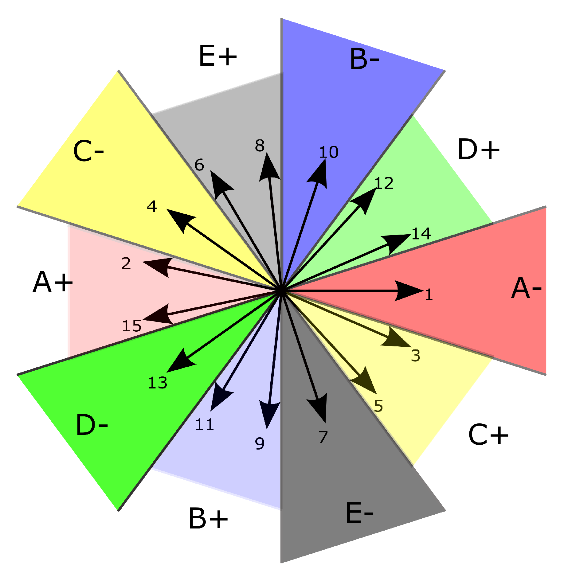
The FSPMSM was equipped with five phases ( q = 5 ) inserted in fifteen double-layer slots ( N s = 15 ) in the stator and fourteen poles ( p = 7 ) made up of surface-mounted rare earth PMs in the rotor. The corresponding star of slots is shown in Figure 10.
The conventional armature winding arrangement with a series connection of the three coils of each phase was treated in [18]. The winding factor was found equal to 0.9800. Considering the proposed armature winding arrangement based on the parallel connection of asymmetrical coils, the winding factor reached up to 0.9945 , with an improvement of almost 1.5% with respect to the conventional armature winding arrangement.
The machine under study has the parameters listed in Table 1.
For the sake of comparison, the machine magnetic circuit, considering both conventional and proposed armature winding arrangements, remained the same. The only difference between the two designs was the slot fill factor, which was constant in the conventional case and variable in the proposed one, with N = 54 , N H = 80 , and N L = 41 . In what follows, a 2D FEA was carried out in order to investigate the no- and on-load operations of the FSPMSM under study, considering both conventional and proposed armature winding arrangements.

3.1. No-Load Operation

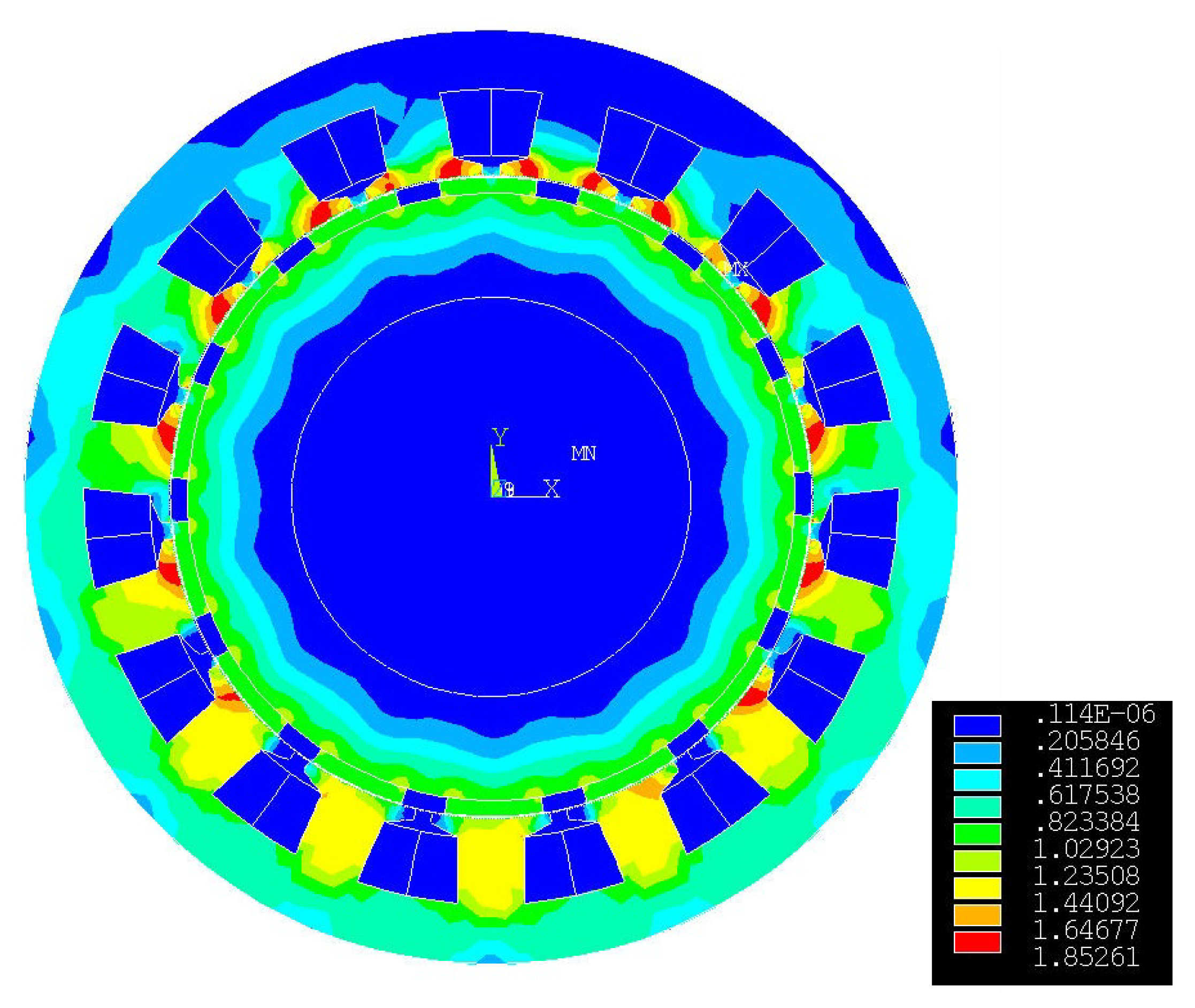
Figure 11 shows the flux density mapping across the total magnetic circuit under no-load operation, which is obviously the same for both conventional and proposed armature winding arrangements. One can notice that the stator magnetic circuit is locally saturated within the tooth tips, which is due to the reduced coil pitch ratio of 9.3%. Such a value has been selected in [18] in order to maximize the torque production.
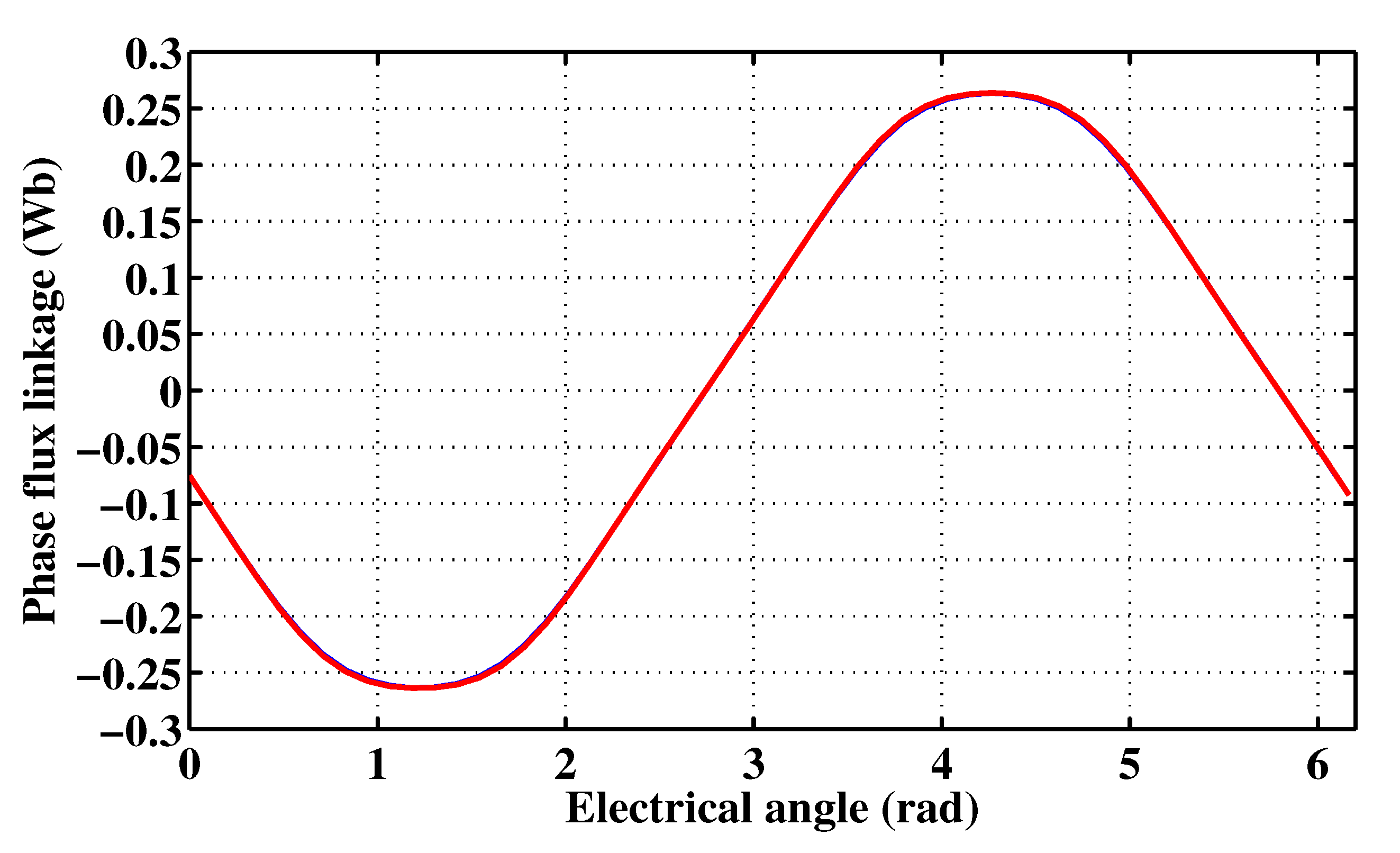
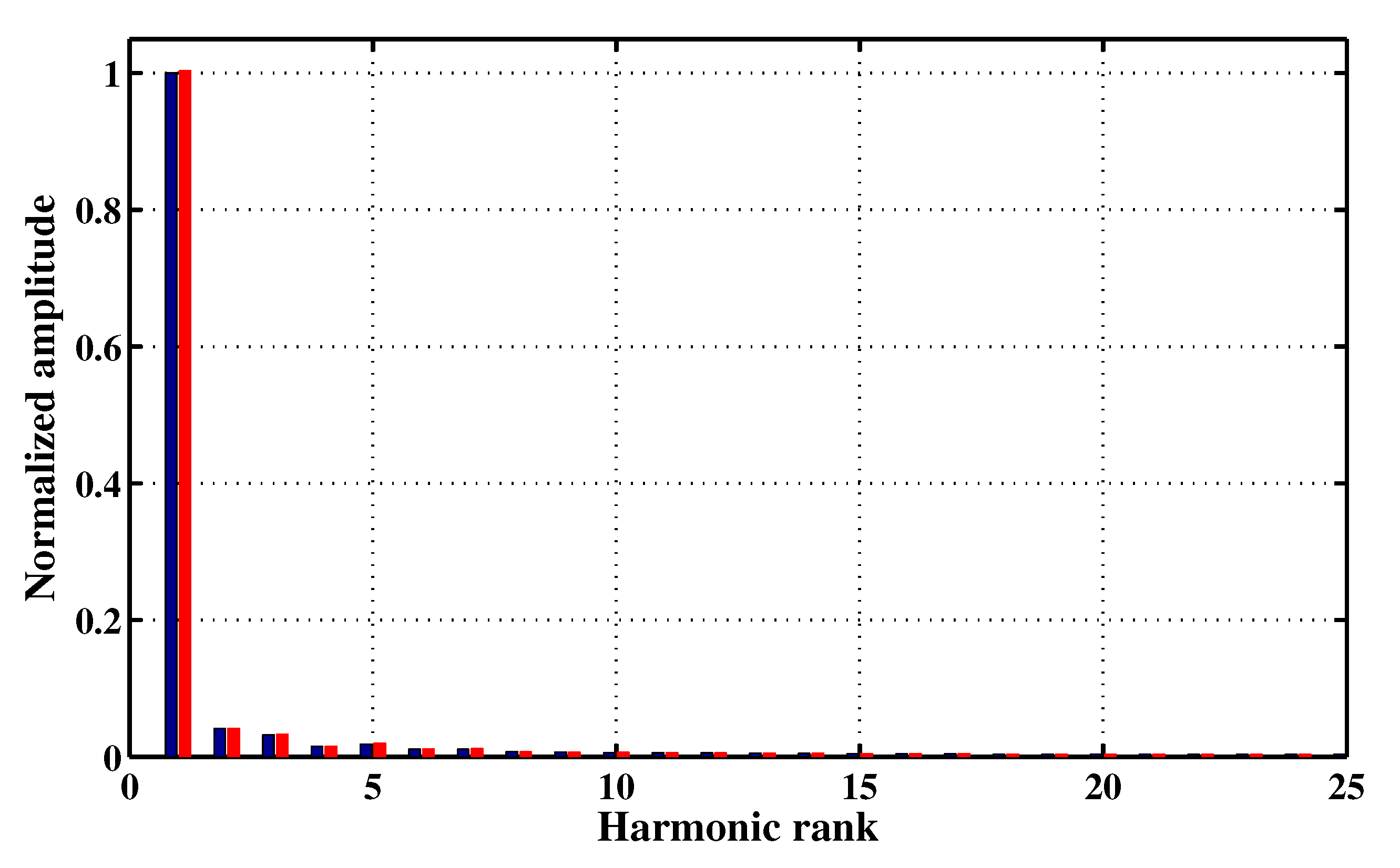
Figure 12 shows the phase flux linkages of both conventional and proposed armature winding arrangements. It clearly appears that these waveforms are almost the same. This statement is confirmed by the fast Fourier transforms (FFT) illustrated in Figure 13, in which one can notice a slight increase in the amplitude of the fundamentals as well as harmonics of ranks three and five when moving from the conventional to the proposed armature winding arrangement. For the sake of a deeper characterization of the tiny disparity between the phase flux linkages of Figure 12, a prediction of their total harmonic distortions (THDs) led to 6.26% and 6.33% for the conventional and proposed armature winding arrangements, respectively.

3.2. On-Load Operation

3.2.1. Healthy Operation

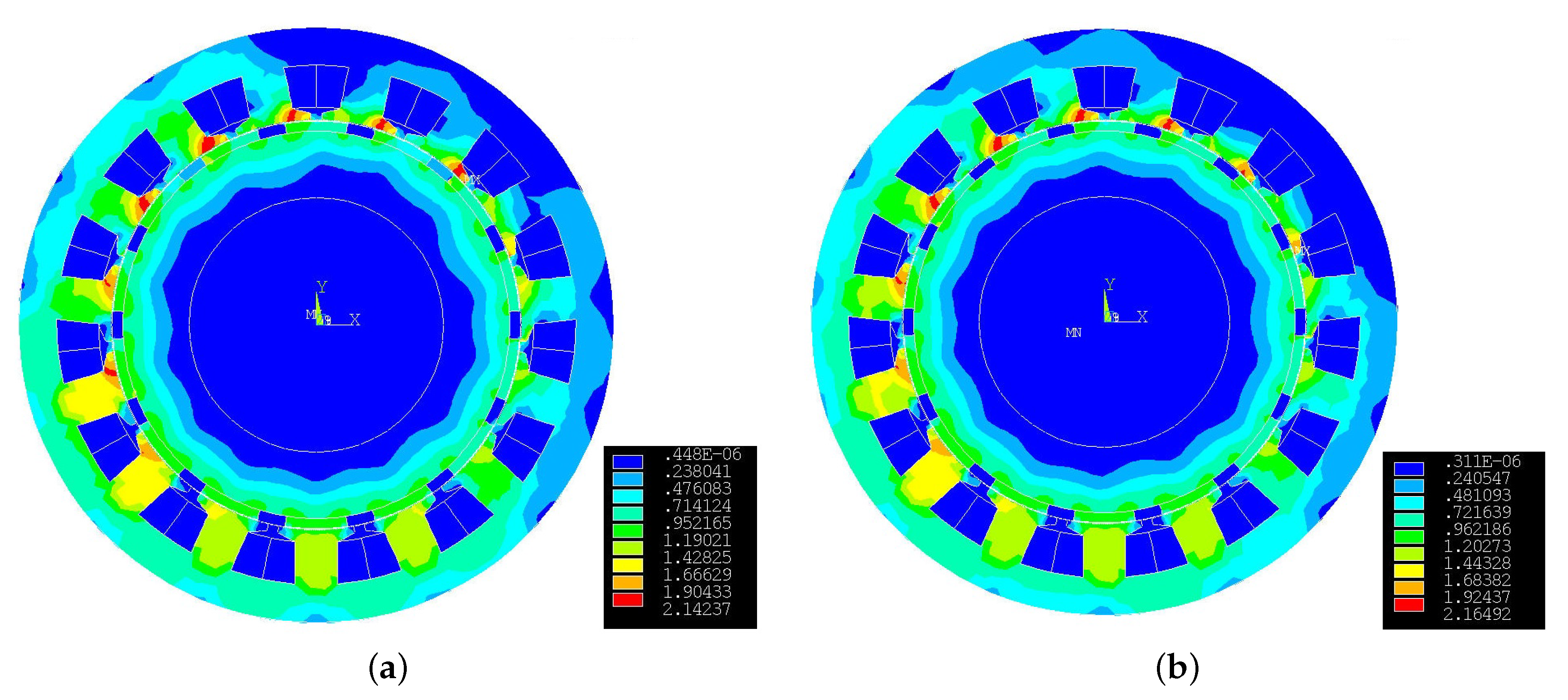
Figure 14 illustrates the flux density mappings across the total magnetic circuit under on-load operation for the coil-rated current rms value of 14 A and for the same rotor position considering the proposed armature winding arrangement (Figure 14a) and the conventional one (Figure 14b). Referring to the scales of these flux density mappings, one can notice that the saturation level is slightly lower in the case of the FSPMSM in which the armature winding is arranged according to the proposed approach.
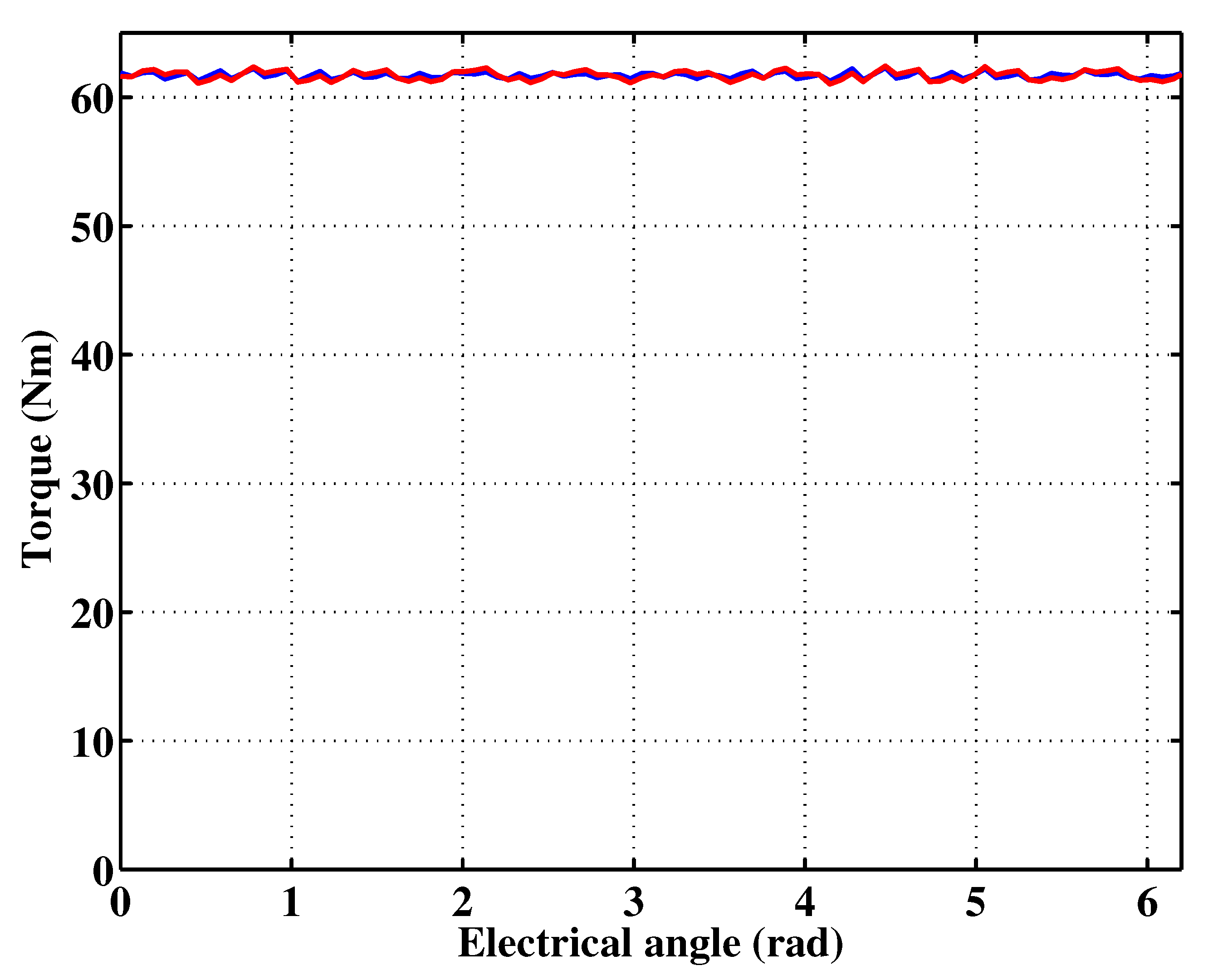
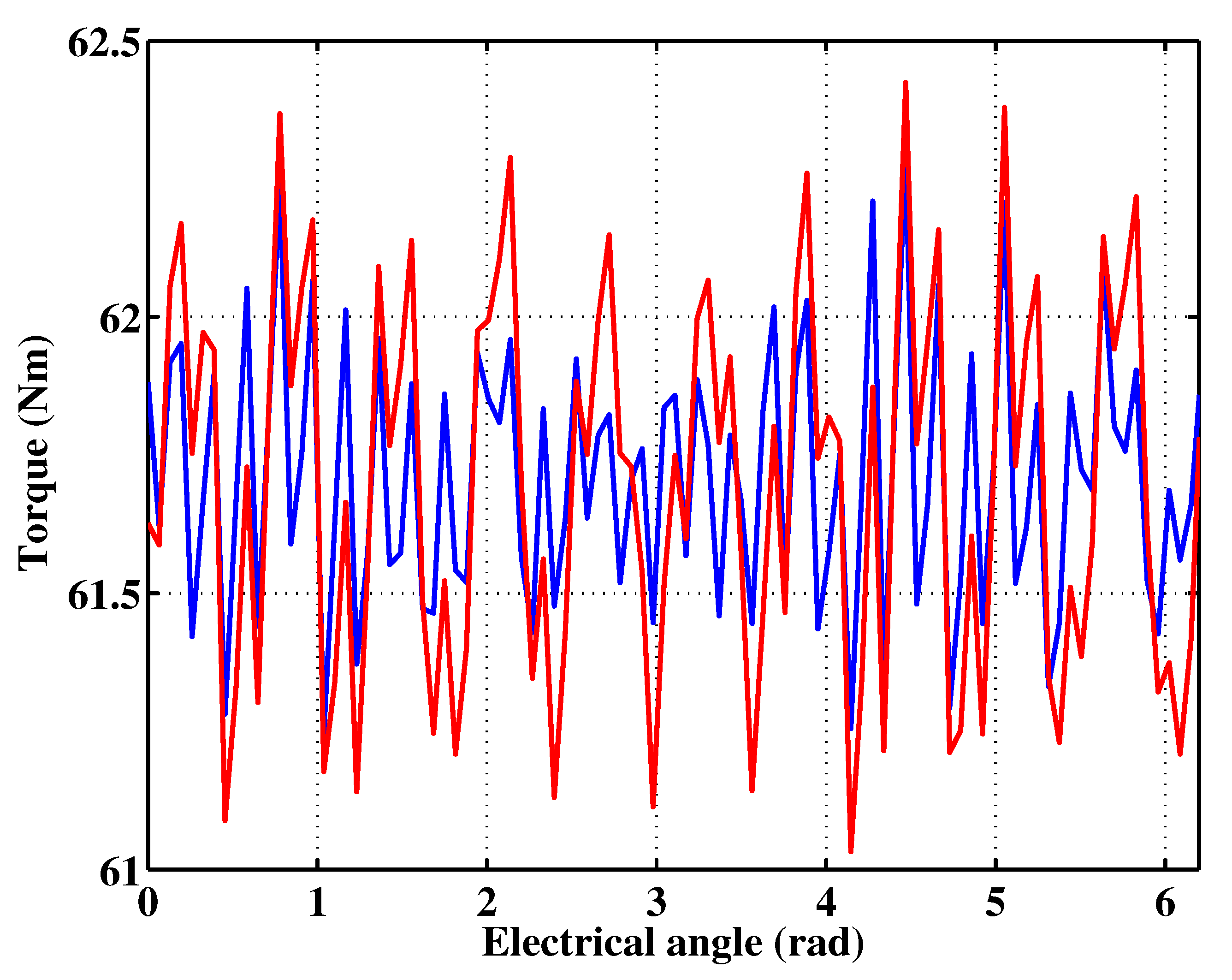
Figure 15 shows the torque-angle characteristics for both cases of conventional and proposed armature winding arrangements and for the coil-rated current rms value of 14 A. Their zoomed view is illustrated in Figure 16. It is to be noted that, while the torque mean values are almost the same, equal to 61.7 Nm, the proposed armature winding arrangement exhibits slightly higher torque ripple.
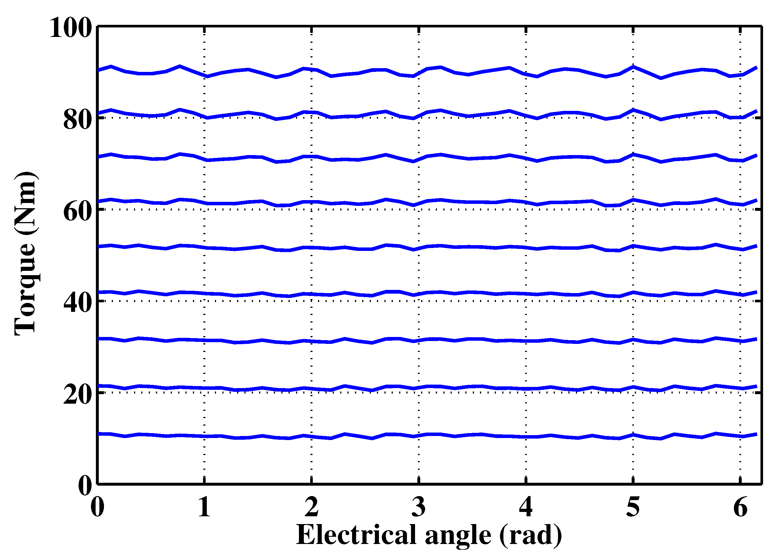
For the sake of a deeper investigation of the saturation on the torque production of the FSPMSM equipped with the proposed armature winding arrangement, the torque angle was investigated by FEA by varying the current density J from 1 to 9 A/mm2, with step 1 A/mm2 (the current density of 6 A/mm2 corresponds to a coil-rated current rms value of 14 A) (Figure 17).

3.2.2. Faulty Operation

This section considers an open-circuit fault affecting a single coil, such that
  • the totality of a phase becomes passive in the case of the conventional armature winding arrangement and
  • two possible faulty scenarios could take place in the case of the proposed armature winding arrangement, as follows:
    -
    a branch of a single coil of N H becomes passive and
    -
    a branch of two series connected coils of N L makes each passive.
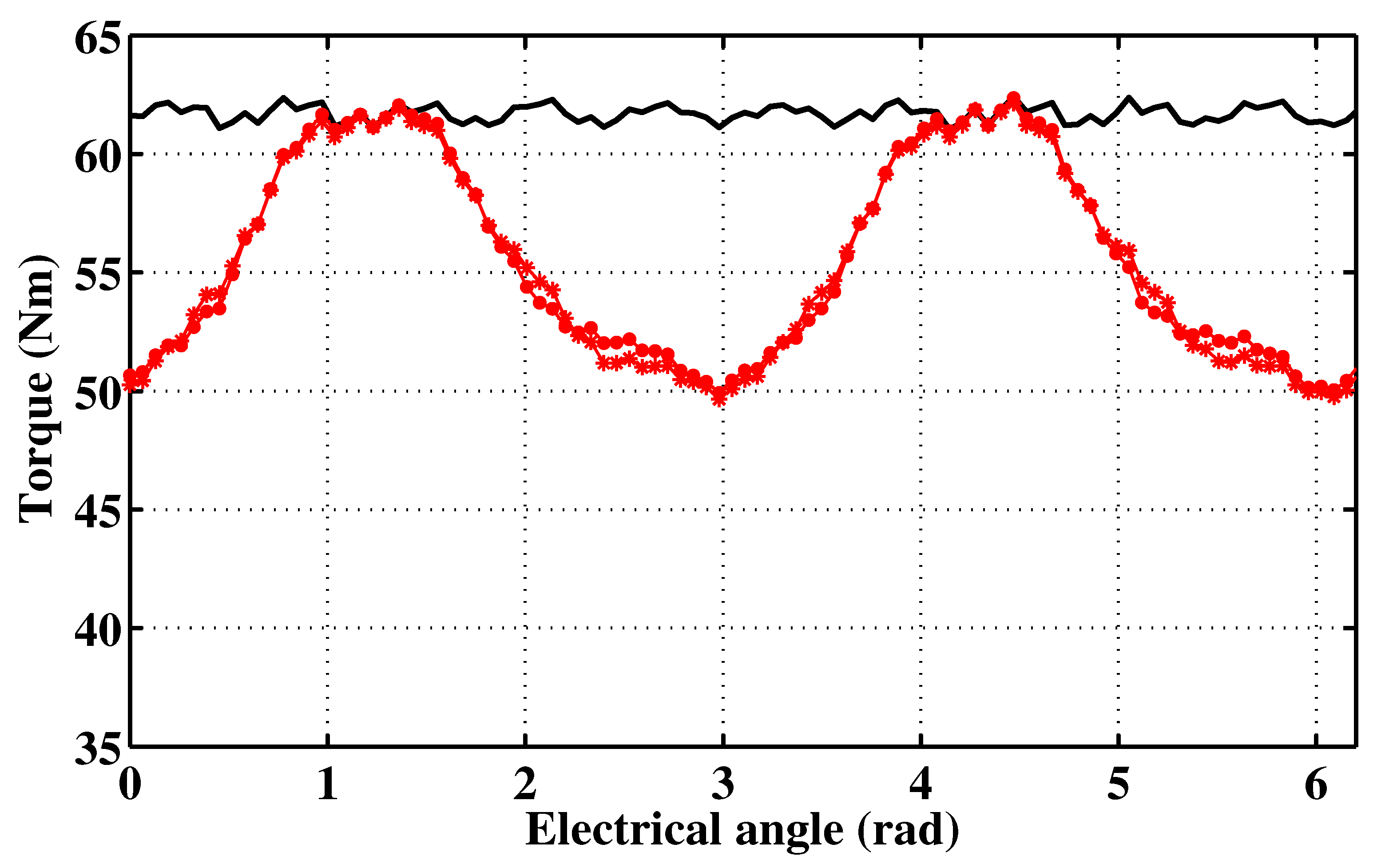
Figure 18 shows the torque-angle characteristics exhibited by the FSPMSM under study considering the above-described faulty scenarios in the case of the proposed armature winding arrangement. The torque-angle characteristic corresponding to the healthy operation of Figure 15 is also recalled in Figure 18. One can notice that the torque-angle characteristics resulting from both faulty scenarios are quite similar to the torque mean value of 55.5 Nm, which corresponds to a loss of torque by 6.2 Nm (10% of the rated torque). The torque ripple to the mean torque ratio does not exceed 22.5%.
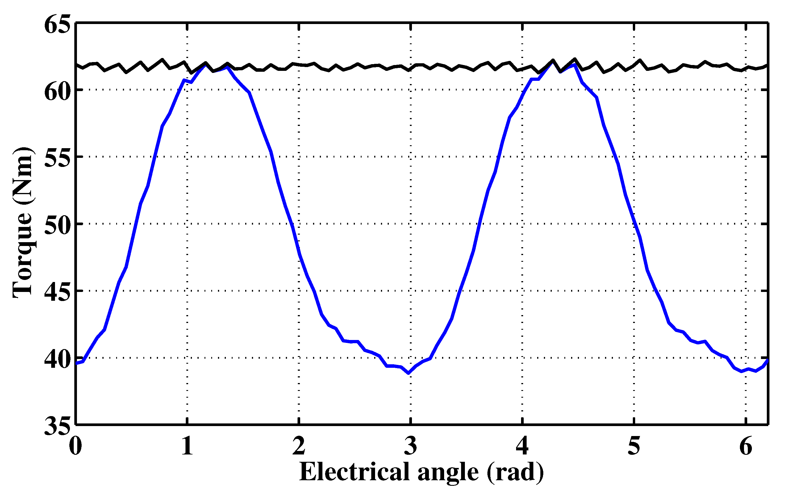
For the sake of comparison, the phase open-circuit fault corresponding to the case of the conventional armature winding was treated. The corresponding the torque-angle characteristic is illustrated in Figure 19, along with the one obtained under healthy operation in Figure 15. As expected, the loss of torque is higher than the one corresponding to the proposed armature winding arrangement. Indeed, the resulting torque mean value does not exceed 49.2 Nm, which corresponds to a loss of torque of 12.5 Nm (20% of the rated torque). The torque ripple to the mean torque ratio reaches up to 47%.

3.2.3. Discussion

To sum up, it has been found that the proposed armature winding arrangement exhibits higher performance over the conventional one, especially under open-circuit faulty operation. The features of the FSPMSM when equipped with the proposed armature winding and when equipped with the conventional one are enumerated in Table 2. The superiority of the proposed winding arrangement over the conventional one could be enhanced considering a simple post-fault recovery of the torque such as the one proposed in the next section.

3.3. Torque Recovery under Open-Circuit Fault

Inspired from the approach presented in [2], a simple torque recovery based on the readjustment of the phase currents was applied to the FSPMSM equipped with the proposed armature winding arrangement. Following an open-circuit fault affecting a coil among three of the a-phase, the FSPMSM is fed by the following currents:
i a = 2 I r m s 2 cos ω t faulty phase i b = 2 I r m s cos ω t 2 π 5 + β healthy phase i c = 2 I r m s cos ω t 4 π 5 + γ healthy phase i d = 2 I r m s cos ω t 6 π 5 γ healthy phase i e = 2 I r m s cos ω t 8 π 5 β healthy phase
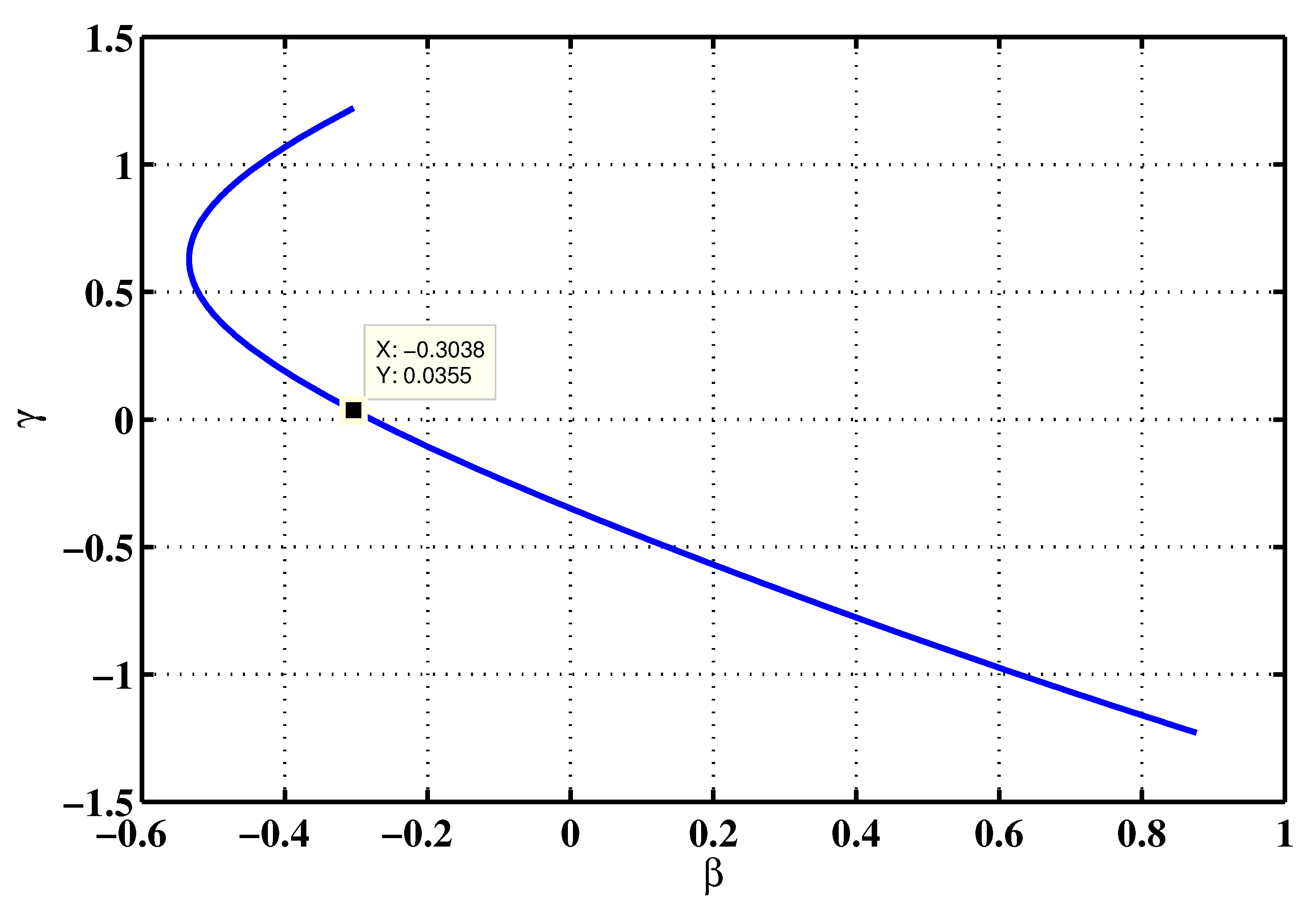
Considering the initial time, the sum of the phase currents is null for a set of angles ( β , γ ) fulfilling the following equation:
cos β + 2 π 5 + cos γ + 4 π 5 = 1 4
A numerical resolution of Equation (8) has led to the locus depicted in Figure 20. Feeding the FSPMSM with the phase currents considering the couple ( β = 0.3038 rad, γ 
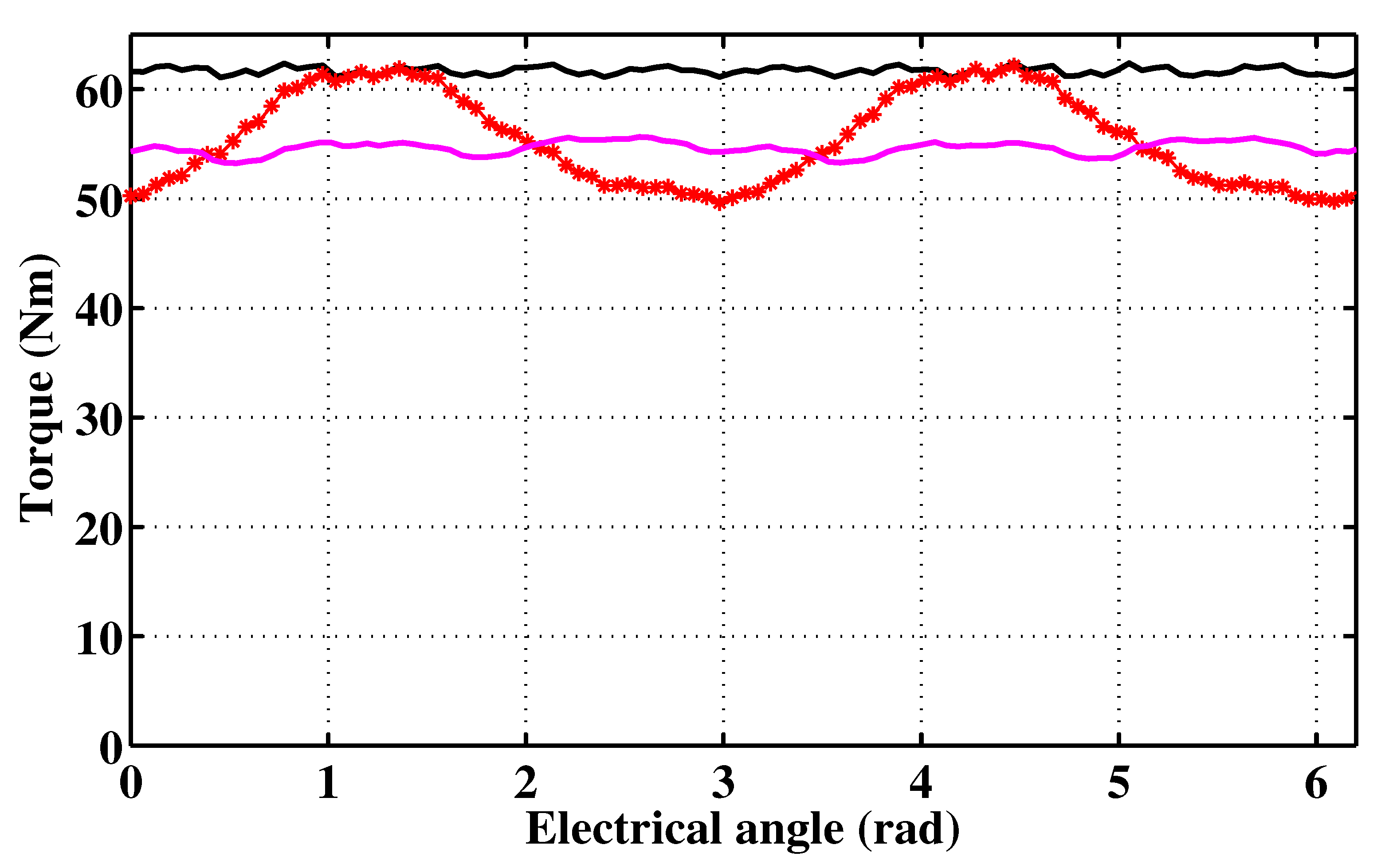
= 0.0355 rad) led to the torque-angle characteristic illustrated in Figure 21, for which one can remark the following:
  • The mean value of the torque is almost the same as that in the case under faulty operation without the phase currents readjustment.
  • A significant decrease in the torque ripple is observed, which is characterized by a torque ripple to the mean torque ratio of 4.4%.

4. Conclusions

This paper dealt with an approach arranging the armature winding of multi-phase FSPMSMs aimed at enhancing open-circuit fault-tolerance capability. The proposed approach considers parallel connection of the coils or suitable combinations of the coils, with emphasis on the candidates which are characterized by a star of slots including three phasors per phase and per winding period.
Special attention has been paid to characterization of the coil asymmetry that makes an asymmetrical phase parallel arrangement possible was compared to that of the conventional arrangement, where the machine phases are made up of series connections of identical coils. It has been found that the proposed armature winding arrangement leads to a remarkably high winding factor that increases with the number of phases.
A case study devoted to a five-phase FSPMSM was treated considering both proposed and conventional armature winding arrangements. An FEA-based investigation of the torque production capability under an open-circuit fault affecting a single coil clearly highlighted the gained open-circuit fault-tolerance thanks to the proposed armature winding arrangement. A torque recovery approach based on readjustment of the phase currents under a one-coil open-circuit fault affecting the FSPMSM equipped with the proposed and conventional armature winding arrangement led to a significant reduction in the torque ripple to the mean torque ratio.
However, there is still some distance to go before the proposed concept becomes a mature technology for automotive applications. Several outlooks, especially (i) optimization of the stator magnetic circuit accounting for the asymmetrical slot filling and (ii) investigation of the possible circulation of harmonic currents in the loops created by the the phase parallel arrangement, will be treated in the future.

Author Contributions

Conceptualization, I.A. and A.M.; methodology, I.A. and A.M.; software, E.H. and I.A.; validation, E.H., I.A., and A.M.; formal analysis, E.H., I.A., and A.M.; investigation, E.H., I.A., and A.M.; writing—original draft preparation, A.M.; writing—review and editing, I.A. and A.M. All authors have read and agreed to the published version of the manuscript.

Funding

This research received no external funding.

Conflicts of Interest

The authors declare no conflict of interest.

References

  1. L-Refaie, A.M.E.; Jahns, T.M. Optimal flux weakening in surface PM machines using fractional-slot concentrated windings. IEEE Trans. Ind. Appl. 2005, 41, 790–800. [Google Scholar] [CrossRef] [Green Version]
  2. Abdennadher, I.; Masmoudi, A. Armature design of low-voltage FSPMSMs: An attempt to enhance the open-circuit fault-tolerance capabilities. IEEE Trans. IEEE Trans. Ind. Appl. 2015, 50, 4392–4403. [Google Scholar] [CrossRef]
  3. Gu, Z.Y.; Wang, K.; Zhu, Z.Q.; Wu, Z.Z.; Liu, C.; Cao, R.W. Torque improvement in five-phase unequal tooth spm machine by injecting third harmonic current. IEEE Trans. IEEE Trans. Veh. Technol. 2018, 67, 206–215. [Google Scholar] [CrossRef]
  4. Zhang, L.; Fan, Y.; Lorenz, R.D.; Nied, A.; Cheng, M. Design and comparison of three-phase and five-phase FTFSCW-IPM motor open-end winding drive systems for electric vehicles applications. IEEE Trans. IEEE Trans. Veh. Technol. 2018, 67, 385–396. [Google Scholar] [CrossRef]
  5. Gong, J.; Zahr, H.; Semail, E.; Trabelsi, M.; Aslan, B.; Scuiller, F. Design considerations of five-phase machine with double p/3p polarity. IEEE Trans. Energy Convers. 2019, 34, 12–24. [Google Scholar] [CrossRef]
  6. Wu, S.; Tian, C.; Zhao, W.; Zhou, J.; Zhang, X. Design and analysis of an integrated modular motor drive for more electric aircraft. IEEE Trans. Transp. Electrif. 2020, 6, 1412–1420. [Google Scholar] [CrossRef]
  7. Scuiller, F.; Becker, F.; Zahr, H.; Semail, E. Design of a bi-harmonic 7-phase pm machine with tooth-concentrated winding. IEEE Trans. Energy Convers. 2020, 35, 1567–1576. [Google Scholar] [CrossRef] [Green Version]
  8. Zhou, H.; Liu, G.; Zhao, W.; Yu, X.; Gao, M. Dynamic performance improvement of five-phase permanent-magnet motor with short-circuit fault. IEEE Trans. Ind. Electron. 2018, 65, 145–155. [Google Scholar] [CrossRef]
  9. Zhang, L.; Fan, Y.; Cui, R.; Lorenz, R.D.; Cheng, M. Fault-tolerant direct torque control of five-phase FTFSCW-IPM motor based on analogous three-phase SVPMW for electric vehicle applications. IEEE Trans. Veh. Technol. 2018, 67, 910–919. [Google Scholar] [CrossRef]
  10. Wang, K.; Gu, Z.Y.; Liu, C.; Zhu, Z.Q. Design and analysis of a five-phase SPM machine considering third harmonic current injection. IEEE Trans. Energy Convers. 2018, 33, 1108–1117. [Google Scholar] [CrossRef]
  11. Cui, R.; Fan, Y.; Cheng, M. A new zero-sequence current suppression control strategy for five-phase open-winding fault-tolerant fractional-slot concentrated winding IPM motor driving system. IEEE Trans. Ind. Appl. 2019, 55, 2731–2740. [Google Scholar] [CrossRef]
  12. Fan, Y.; Cui, R.; Zhang, A. Torque ripple minimization for inter-turn short-circuit fault based on open-winding five phase FTFSCW-IPM motor for electric vehicle application. IEEE Trans. Veh. Technol. 2020, 69, 282–292. [Google Scholar] [CrossRef]
  13. Chen, C.; Zhou, H.; Wang, G.; Liu, G. Unified decoupling vector control of five-phase permanent-magnet motor with double-phase faults. IEEE Access 2020, 8, 152646–152658. [Google Scholar] [CrossRef]
  14. Liu, Y.; Zhu, Z.Q. Influence of gear ratio on the performance of fractional slot concentrated winding permanent magnet machines. IEEE Trans. Ind. Electron. 2019, 66, 7593–7602. [Google Scholar] [CrossRef] [Green Version]
  15. Zhang, B.; Du, B.; Zhao, T.; Cui, S. Research on the combinations of pole and slot for twelve-phase fractional-slot concentrated-winding permanent magnet motor. In Proceedings of the 2019 Twenty Second International Conference on Electrical Machines and Systems (ICEMS), Harbin, China, 11–14 August 2019. [Google Scholar]
  16. Harke, M. Design of fractional slot windings with coil span of two slots for use in six-phase synchronous machines. J. Eng. 2019, 2019, 4391–4395. [Google Scholar] [CrossRef]
  17. Liang, Z.; Liang, D.; Kou, P.; Jia, S. Postfault control and harmonic current suppression for a symmetrical dual three-phase SPMSM drive under single-phase open-circuit fault. IEEE Access 2020, 8, 67674–67686. [Google Scholar] [CrossRef]
  18. Haouas, E.; Abdennadher, I.; Masmoudi, A. An approach to optimize the stator circumferential geometry of a five phase FSPMSM. In Proceedings of the 2015 Tenth International Conference on Ecological Vehicles and Renewable Energies (EVER), Monte Carlo, Monaco, 31 March–2 April 2015. [Google Scholar]
Figure 1. Star of slots of the fractional-slot permanent magnet (PM) synchronous machines (FSPMSMs) with an odd number of phases arranged in double-layer slots in the case where the phasors of the back-EMFs induced in the coils of a given phase are colinearly aligned in one sector among the two assigned to the phase.
Wevj 12 00032 g001
Figure 2. Star of slots of FSPMSMs with an odd number of phases arranged in double-layer slots in the case where the phasors of the back-EMFs induced in the coils of a given phase are colinearly equally distributed in the two opposite sectors assigned to the phase.
Wevj 12 00032 g002
Figure 3. Connection of the coils of a phase: (a) the case of Figure 1, (b) the case of Figure 2.
Wevj 12 00032 g003
Figure 4. Winding factor of FSPMSMs having an odd number of phases made up of the parallel connection of their coils. Legend: (red) case of Figure 1, (blue) case of Figure 2.
Wevj 12 00032 g004
Figure 5. Star of slots of the FSPMSMs with an odd number of phases arranged in double-layer slots under investigation.
Wevj 12 00032 g005
Figure 6. Connection of the coils of a phase according to the proposed approach.
Wevj 12 00032 g006
Figure 7. Number of turns per coil ratio versus the number of phases q. Legend: (red) N H N , (blue) N L N .
Wevj 12 00032 g007
Figure 8. Number of conductors per slot ratio versus the number of phases q. Legend: (red) N H + N L 2 N , (blue) 2 N L 2 N .
Wevj 12 00032 g008
Figure 9. Big to small slot number of conductors ratio N H + N L 2 N L versus the number of phases q.
Wevj 12 00032 g009
Figure 10. Star of slots of the five phase FSPMSM under study.
Wevj 12 00032 g010
Figure 11. Flux density mapping under no-load operation.
Wevj 12 00032 g011
Figure 12. Phase flux linkages versus electrical angle. Legend: (red) proposed armature winding arrangement, (blue) conventional armature winding arrangement.
Wevj 12 00032 g012
Figure 13. Phase flux linkage fast Fourier transform (FFT), where the amplitudes have been normalized to the one of the fundamental components in the case of the conventional armature winding arrangement. Legend: same as in Figure 12.
Wevj 12 00032 g013
Figure 14. Flux density mappings for a current of 14 A rms corresponding to the coil-rated one. Legend: (a) proposed winding arrangement, (b) conventional winding arrangement.
Wevj 12 00032 g014
Figure 15. Torque-angle characteristics for the coil-rated current rms value of 14 A. Legend: same as in Figure 12.
Wevj 12 00032 g015
Figure 16. Zoom view of the torque-angle characteristics of Figure 15.
Wevj 12 00032 g016
Figure 17. Torque-angle characteristics of the FSPMSM equipped with the proposed winding arrangement vs. the current density. Legend: (bottom) J = 1 A/mm2, (top) J = 9 A/mm2.
Wevj 12 00032 g017
Figure 18. Torque-angle characteristics for the coil rated current rms value of 14 A in the case of the proposed armature winding arrangement. Legend: (red dots) faulty scenario corresponding to the case where a branch of a single coil of N H is passive, (red stars) faulty scenario corresponding to the case where a branch of two series connected coils of N L turns each is passive, (black) healthy operation.
Wevj 12 00032 g018
Figure 19. Torque-angle characteristics for the coil rated current rms value of 14 A in the case of the conventional armature winding arrangement. Legend: (blue) faulty scenario corresponding to the case of a passive phase, (black) healthy operation.
Wevj 12 00032 g019
Figure 20. Locus of the solutions of Equation (8) in the ( β , γ ) plane.
Wevj 12 00032 g020
Figure 21. Torque-angle characteristics for the coil rated current rms value of 14 A in the case of the proposed armature winding arrangement. Legend: (pink) one-coil open-circuit fault with readjustment of the phase currents, (red stars) one-coil open-circuit fault without readjustment of the phase currents, (black) healthy operation.
Wevj 12 00032 g021
Table 1. FSPMSM parameters.
ParameterValue
Stator outer radius R m 117 mm
Stator inner radius R s 80.5 mm
air gap thickness e1 mm
Rotor outer radius R m 80 mm
PM height H p m 4 mm
Active length L a 90 mm
PM relative permeability μ r 1.05
PM residual flux density B r 1.1 T
Table 2. Comparison of the features of the FSPMSM under study when equipped with the proposed armature winding and when equipped with the conventional one.
Proposed ArmatureConventional Armature
winding arrangementwinding arrangement
Winding factor0.99450.9800
THD of the no-load phase flux linkage6.33%6.26%
Saturation level for J = 6 A/mm22.14237 T2.16492 T
Torque loss ratio under one-coil
open-circuit fault for J = 6 A/mm210%20%
Torque ripple to mean torque ratio under
one-coil open-circuit fault for J = 6 A/mm222.5%47%
Publisher’s Note: MDPI stays neutral with regard to jurisdictional claims in published maps and institutional affiliations.

