Abstract
This paper deals with the complete design procedure, implementation and control software realization for a multi-converter charging station with reduced grid impact due to local electromechanical energy storage. In particular, energy storage is accomplished by a dedicated flywheel designed and built for this purpose. The proposed charging station was designed for ultra-fast charging procedures presenting a strongly reduced impact on the electrical grid. Modes of operations are described with reference to pure electric buses in public transportation applications.
1. Introduction
1.1. General Context and Motivation
Today, despite the progress made in the transport sector in the reduction of the dependency on fossil fuels and air pollution, most vehicles use petroleum as the energy source [1]. Although more and more countries have begun the integration of Electric Vehicles (EVs) and charging stations into their power grids, these efforts are still not enough [2]. It is clear that the charging infrastructures must keep up with the growing number of EVs. In this scenario, the electricity grid plays a major role. In fact, the stability of the power distribution grid becomes critical during rush hours of the day due to the high energy demand, which could lead to serious grid management problems. One solution to overcome this problem is to reinforce the existing grid infrastructures and/or create new networks in such a way that they can fully handle the EVs integration. Obviously, this solution is rather expensive and requires high-value investments in network infrastructures. A very simple, cheap, and quick solution to solve the aforementioned problem is the development and the implementation of charging stations using renewable energy sources and/or energy storage systems that help the electric grid [3,4,5]. Another aspect to consider is the time required to charge the EVs. For instance, charging twenty EVs in twenty minutes would require the use of equipment capable of supplying a large amount of electricity. Thus, as the number of EVs increases, the need to install efficient fast-charging stations grows. Fast charging architectures equipped with powerful energy storage systems are an attractive choice because they allow much faster charging than the standard AC [6]. For this purpose, chemical accumulators similar to those in EV batteries can be used in the fast-charging architecture, but their disadvantage is that frequent charging and discharging shortens their lifetime [4,7]. Thus, the problem of recycling the batteries in an environmentally friendly way remains to be addressed, which is a tricky and energy-expensive process.
1.2. State of the Art
Although the development of Li-ion batteries is still ongoing, there are already energy storage devices that have much longer lifetimes than those belonging to previous generations [7,8]. Besides the chemical accumulators, another promising and emerging way to accumulate energy is to exploit kinetic energy using flywheels [9,10]. In fact, flywheel energy storage offers many advantages over the alternatives [11]. The use of energy storage systems that help the electrical grid requires, of course, efficient power conversion systems. Power electronics are a fundamental part of the fast-charging station. The right choice of the power converters’ topologies and the selection of the power semiconductors are the key factors in improving the efficiency and the power density of the charging units [12,13]. In [14] the electric bus was equipped with a pantograph in order to test the Flash Charge (at the bus stop), as illustrated in Figure 1.
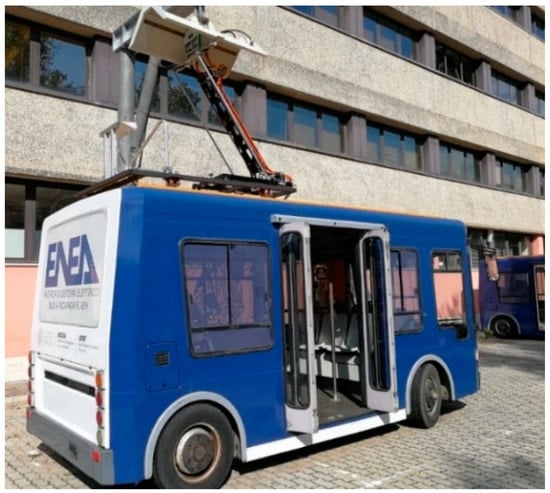
Figure 1.
Electric bus, part of the experimental test rig at ENEA Casaccia Research Center.
In this paper, to properly design a new onboard storage system, the information about the route of the electric bus including its energy consumption is absolutely needed [15,16,17]. Thus, the results obtained from the previous work are used and illustrated in Figure 2. Battery energy is the total amount required for the mission profile. Traction indicates the amount of energy required by the electrical drive according to the specific driving cycle. Finally, charging shows the amount of energy needed before a new driving cycle can be performed.
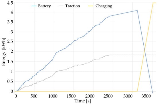
Figure 2.
Energy consumption and charged during line 117 and recalculated for the “modified fast charge line” with high specific energy storage and a fast charge at the terminal with a flywheel as ground storage.
In this paper, the electric bus used for the experimental campaign covers line 117 in the city of Rome, as illustrated in Figure 3a.
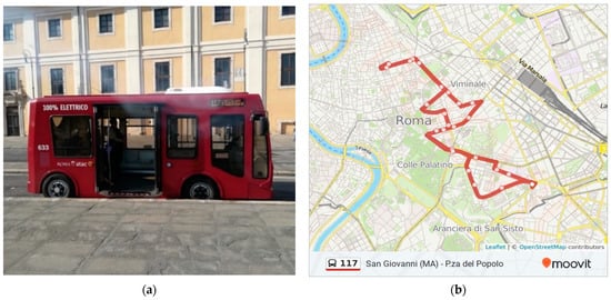
Figure 3.
Electric bus line 117 in Rome (Italy): (a) picture of the bus, (b) daily route of the bus.
The main information to properly design the onboard storage system are the minimum energy required and the maximum discharge and charge power; the needed energy for line 117 is about 4 kWh, while the discharge power can be set to the maximum motor power (about 24 kW) and the charge power is the value of the charging station (about 40 kW, minimum). The limiting parameter for this application is the energy request for the LTO battery; in fact, with 3C of maximum continuous current value, a capacity of about 15 kWh must be used [18,19]. This type of high-power recharging process has the advantage of reducing the accumulation onboard the vehicles with great advantages in terms of its cost and maintenance of the same. However, high charging powers can also cause problems:
- from the point of view of the electricity network operator, who has to manage very high loads for short and intermittent times, as well as the impossibility of supplying the high powers due to an inadequate electricity network. A storage unit on the ground can reduce the demand for power to the network by contributing to the fast recharge of the bus and subsequently being recharged at lower power;
- for the charging mode, high energy and low charging times need automated systems that do not require the presence of an operator;
- for onboard storage units, due to the involved high energy, batteries with higher specific energy than most of the batteries available on the market are required, with a high number of life cycles at high currents and with a carefully sized cooling system.
1.3. Contribution
This paper focuses on the design, implementation and control of a particular fast-charging station composed of different power converters. Particularly, the proposed power architecture aims to increase efficiency and power density. Furthermore, the energy storage system is realized using a specially designed flywheel. The benefits of the proposed fast-charging station were evaluated, designed, and experimentally verified on a minibus operating on a real mission profile. A daily route of a minibus was fixed and all the kinematic parameters were recorded, while all the electric parameters were calculated using the simulator in [20]. Figure 3b shows the daily route and the electric bus manufactured by the Tecnobus model Gulliver and it operates in the center of the city [20]. Three routes were measured with a GPS tracker to collect the driving cycle to be used for the offline simulations in order to calculate several parameters such as the time to run the mission, the available time for the charging process, the energy consumption, etc... The route is made with four buses (four bus/hour) and each bus starts its mission one time per hour, but the time needed to start and return to the terminal is about 45 min, so that 15 min is available to charge the onboard battery with a newly conceived charging system, able to reduce the grid impact for such a short charging time. According to the experimental measurements, an average load of eight passengers was assumed.
The complete characteristics of the bus line are reported in Table 1. With a distance covered of 8.34 km at an average speed of 12.4 km/h, the electric bus has an energy consumption of about 3.98 kWh (0.481 kWh/km). A modified electric bus was designed to test the fast-changing technology with ground storage based on a flywheel electromechanical system [21,22]. The new electric bus has the following characteristics: (1) a pantograph to allow automatic charge when the bus reaches the terminal; (2) a new onboard storage system, consisting of low capacity, high specific power which can be charged at high power. The technology chosen for this application is the LTO battery (Lithium-Titanate Oxide) [23,24,25]; (3) a fast charger with a flywheel energy storage.

Table 1.
Characteristics of the electric bus line 117 in Rome accomplished with a Tecnobus Gulliver.
1.4. Paper Organization
This paper is organized as follows: the proposed power conversion system including the designed energy storage system is discussed in Section 2. The control strategies for the different power electronic converters belonging to the fast-charging architecture are presented in Section 3. The experimental results for the subsystems charging station are discussed in Section 4 and finally, the conclusions of the paper are given in Section 5.
2. Charging Station
The proposed charging station block scheme is illustrated in Figure 4, where different power conversion systems are connected to the DC-bus. Particularly, the 3-phase 5-Level E-Type Rectifier, called 3Φ5L E-Type Rectifier (proposed, investigated and designed by Roma Tre University, Rome, Italy and manufactured by “Sky Research doo” company, Belgrade, Serbia), is used as a front and between the electrical grid and the DC-bus, and the bidirectional Dual Active Bridge (DAB) DC–DC Converter is employed as a charging architecture. Another the 3-phase 5-Level E-Type Inverter, called 3Φ5L E-Type Inverter (proposed, investigated and designed by Roma Tre University, Rome, Italy and manufactured by “Sky Research doo” company, Belgrade, Serbia) is used to control the flywheel. Figure 5 shows the charging station cabinet which integrates both the power conversion systems and the control architecture.
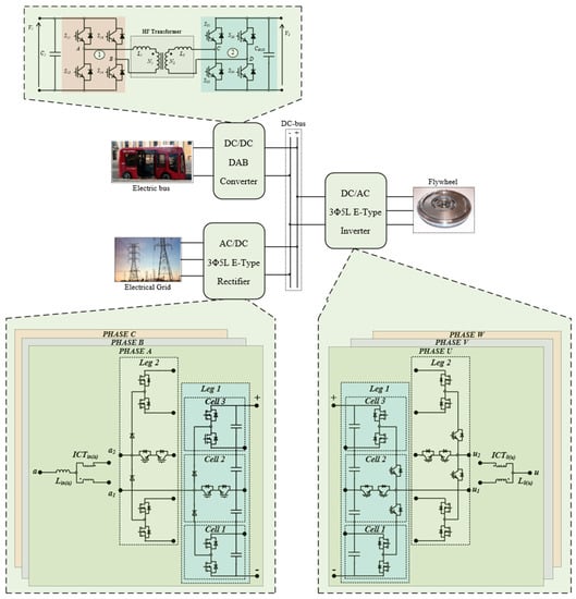
Figure 4.
Block scheme of the proposed ultra-fast charging station.
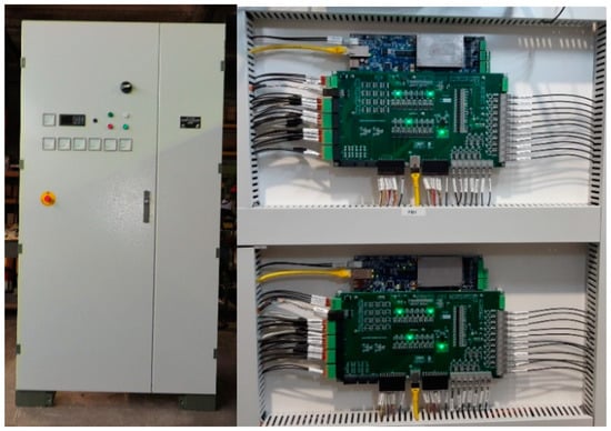
Figure 5.
Charging station with integrated power electronics converters and control platforms.
2.1. Multilevel Converters
Each phase of both 3Φ5L E-Type Rectifier and Inverter have two interleaving legs: leg 1 and leg 2, as shown in Figure 4. Additionally, each leg is composed of two I-Type cells (cell 1 and cell 3) connected to the T-Type cell (cell 3) [26]. Furthermore, the power flows in one direction in the 3Φ5L E-Type Rectifier due to the presence of the diode into the T-Type cell. The two legs are connected in interleaving using the Intercell Transformer (ICT) [27]. The advantages of paralleling the legs using the ICT lies in the fact that the phase current is equally shared between the legs, the amplitude of the total current ripple is reduced and the harmonic contents of the voltage at high frequency are shifted at twice the switching frequency. The main idea of using the five-level converter is to improve the equality of the voltage and current waveforms without giving up the benefit of high efficiency and high-power density [28,29,30]. In fact, keeping constant the switching frequency and the other passive parameters, increasing the number of voltage levels means reducing the current ripple, which leads to a low Total Harmonic Distortion (THD). Furthermore, by working with only a fraction of the DC-bus, it is possible to select the power semiconductors with a low voltage rating.
The use of high-speed power semiconductors allows the reduction of the switching losses or, alternatively, keeping the power losses constant, it is possible to play with the switching frequency fsw to reduce the volume of the passive components. As can be deducted, the voltage stress across the power semiconductors was reduced by using the multilevel topology, whereas the current stress flowing through the power semiconductors was reduced by using the interleaving topology. Obviously, no meal is free! As the number of levels increases, the number of power devices in the converter also increases, which is not at all advantageous from the reliability point of view. However, in the last few years, power semiconductors have become more and more reliable [31,32] and their cost has drastically reduced compared to the cost of copper and iron, which are the main elements for making inductors or transformers. The other disadvantage of having a large number of devices could lie in the control circuits to ensure the best input and output characteristics. In fact, it is difficult to find an analytical model to predict their dynamic characteristics due to the non-linear nature of the power semiconductors. Thus, the linearization of the power converter behavior is on the basis of a more predictable tuning procedure of the related control loops [33,34]. Nevertheless, apart from the analytical effort required to find the control law, the continuous trend of increasing controller performance and memory size along with the reduction of cost has now reached a point where the increase in the number of power semiconductors is not such a disadvantageous problem. Figure 6 shows the realized DC–AC converter used for both grid-tied converter and flywheel controller. The AC filter board that was accurately designed to comply with the grid connection standard is also shown.

Figure 6.
Prototype of the DC–AC converter and its output power filter.
2.2. Dual Active Bridge Converter
The charging and/or discharging power transfer from the battery onboard the Electric Buses (EB) to the DC-side is controlled by a bidirectional DC–DC DAB Converter [35,36,37]. The DAB converter is an isolated bidirectional converter that can transfer energy in two directions. It consists of two active full bridges, which are symmetrical from both sides, connected to a High-Frequency Transformer (HFT), as illustrated in Figure 4. The transformer leakage inductances L1 and L2 work as a power link between the input side and output side, in other words, they can be used as the main component for transferring energy. In fact, the leakage inductance determines the maximum transferable power for a given switching frequency. The operating principle of the DAB is based on phase shift control: the outputs of two voltage bridges are phase-shifted from each other by the phase shift angle ϕ [38,39]. Then, by changing the angle, the amount of power transferred between two bridges can be controlled. In this configuration, the key factor of the fast charging is the galvanic isolation obtained by using the HFT, which is very advantageous from the weight and size point of view [35,36,37,38,39]. Consequently, the main advantages of this fast-charging architecture are wide Zero Voltage Switching (ZVS) range for all the power switches over wide load variation, which means efficiency improvement, naturally bidirectional power flow control and galvanic isolation at high frequency.
2.3. Flywheel Energy Storage System
According to the mission profile, a suitable flywheel energy storage system (FESS) was designed including the electrical machine used as a motor/generator unit and the dedicated power converter to be connected to a common DC-bus. FESS was made of steel and fully encapsulated in a vacuum chamber, as shown in Figure 7. In the same chamber, the permanent magnet’s electrical machine was placed, equipped with liquid cooling. Magnetic bearings were used for mechanical support of the rotating assembly. The characteristics of the flywheel total assembly are listed in Table 2. Minimum speed can be reached thanks to the high efficiency low losses AC–DC converter that will be able to boost the machine phase voltages considering a constant DC-bus shared among the power converters being part of the charging station. Flywheel will be installed according to underground installation standards. This will also reduce the land occupation on the surface.
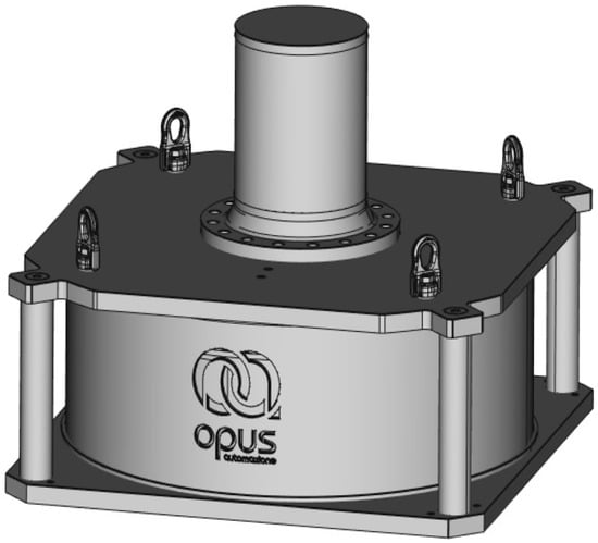
Figure 7.
Totally encapsulated Flywheel and its Permanent Magnet -electrical machine.
Table 2.
Characteristics of the flywheel total assembly.
3. Control System and Implementation
The charging station control scheme was accomplished by three control boards, each one devoted to a specific system as a flywheel, grid-tied AC–DC and charging regulator DC–DC converter. Communication between each apparatus was developed by using TCP/IP standard which allows also remotely monitoring the complete station. The control board is based on the National Instruments sbRIO-9651 System on Module (SoM) which is integrated into the PED-Board® controller (manufacturied by ED-Elettronica Dedicata SRL, Rome, Italy) shown in Figure 8. For the SoM equipped with a dual-core μP and an FPGA, code splitting between targets was accomplished as follows. Control loop for currents, voltage, and speed (when needed) are closed on the FPGA using 32-bit floating-point arithmetic, whereas system managements, state machine and communication infrastructure are totally managed by the ARM μP.
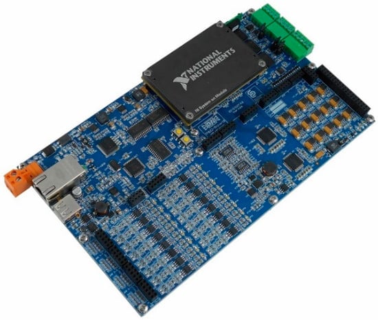
Figure 8.
μP-Field Programmable Gate Array (FPGA) combined control platform for the proposed charging station.
The grid-connected boost rectifier control scheme is shown in Figure 9. This power converter is responsible to keep the common DC-bus voltage regulated to a suitable value that is equal to VBUS. This task is performed by an external voltage loop which provides the current reference to the inner current controllers working on each phase separately. In fact, the current control strategy was selected to be able to perform a wave shaping of the current profile, reducing the total THD. Because the grid frequency cannot be considered as constant, a frequency adaptive multi-resonant control (MRC) structure was selected to fulfill this task. The flywheel energy storage system is composed mainly of an electrical drive with a huge inertial load, and the most suitable control scheme is represented by the Field-Oriented structure as shown in Figure 10.
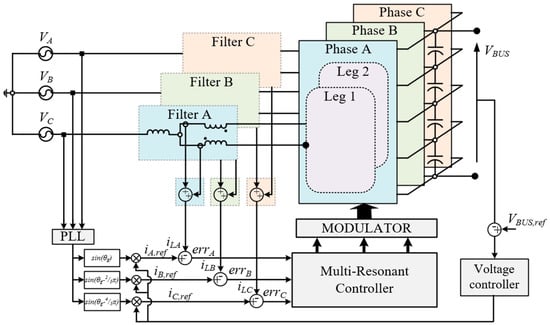
Figure 9.
Block scheme of the 3Φ5L E-Type control algorithm for the grid-tied rectifier.
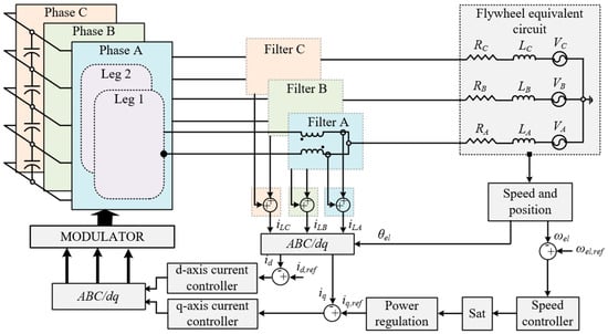
Figure 10.
Block scheme of the 3Φ5L E-Type Inverter control algorithm for the flywheel energy storage system.
This system is controlled by regulating the inner quantities such as machine flux and torque, by an external speed loop. However, that is not enough to keep the system working properly. Because the FESS must follow the charging power on the battery side, an additional power controller is mandatory for this application. The power controller acts in order to modify the torque (i.e., q-axis current) demanded by the speed loop. Expressions used to cut the torque requests are reported as in Equation (1), where P is the machine pole-pairs, and λf is the machine flux. Statements in Equation (1) were integrated into the speed loop anti-windup algorithm changing its maximum and minimum limits. Pcharge and Pdischarge are received by the FESS control board from the DAB controller which regulates the charging process. In this manner, the grid-connected AC–DC is able to keep the DC-bus voltage constant acting as balance and providing extra power when needed.
A Dual-Active-Bridge (DAB) converter topology was selected and designed to manage the batteries charging process. As previously illustrated in Figure 1, when the bus approaches the charging point, its pantograph is activated, and the secondary side of the DAB is energized. After that, the power transfer begins.
As illustrated in Figure 11, two cascaded control loop s can be identified, an inner current loop and an outer voltage loop. This is because the charging process requires separated action, starting with constant current charging, and moving to constant voltage in order to avoid any damage to the battery pack. During the charging phase, power is provided mainly by the flywheel system, taking to the grid only a small part of the whole charging power; hence, reducing the grid impact. The presence of a high-frequency transformer can also be observed, which provides galvanic isolation between the battery on-board the vehicle and the charging station DC and AC sides. It was designed and built to operate at 20 kHz to reduce its weight and size. It is important to add some specific info about the designed charging station. Each component is design id it is inherently bidirectional with respect to the power flow. Flywheel and grid-tied inverters are bidirectional due to their structure. The DAB power converter, which represents a power link and charging regulator between the common DC-bus and the battery onboard vehicle, was designed with active rectification which will allow to reverse the power flow, introducing the so-called vehicle-to-grid [40,41].
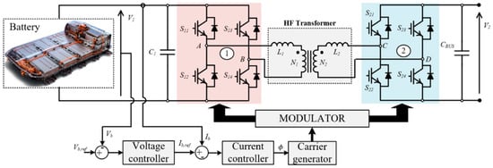
Figure 11.
Block scheme of the Dual Active Bridge (DAB) control algorithm devote to regulate the charging of onboard batteries.
3.1. Control Tuning of the 3Φ5L E-Type Rectifier System
The single-phase Phase-Locked loop (PLL) block shown in Figure 9 and used to obtain the grid phase θg was implemented according to the method presented in [42]. The amplitude of the reference current is given by the external voltage PI controller. The PI controller was discretized using the forward Euler technique and the parameters are tuned according to [43]. The resulting expression in the z-domain is given in Equation (2), where KP and KI are the proportional and the integral gains and Ts is the sampling period.
The amplitude of the obtained current is compared with the measured current and the error signal goes into the MRC block. The transfer function of the MRC GMRC(h)(s) is written in Equation (3), where h is the number of harmonics, kir(h), n is the maximum harmonic order that is included in the MRC and θ(h), ωcr(h), and ω0(h) are the gain, phase, width and resonance frequency of the controller, respectively.
As it can be seen, in each resonant controller it is possible to regulate the gain kir(h), the width ωcr(h) and the phase θ(h). In order to implement the MRC on the FPGA, Tustin’s discretization method with the prewarping term KT was used. The MRC transfer function GMRC(h)(s) in the z-domain is given in Equation (4), where the coefficients are listed in (5).
The control tuning is based on the procedure presented in [44]. Figure 12 shows the open loop of the control structure up to the 17th harmonic when the power is close to 10 kW. It can be seen that the phase at the resonant frequency is equal to zero, due to the phase compensation of the MRC.
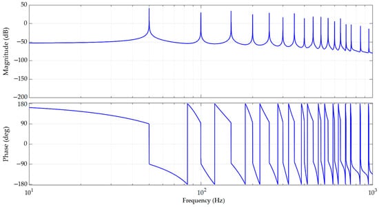
Figure 12.
Open-loop Bode plots of the control structure.
3.2. Control Tuning of the 3Φ5L E-Type Inverter System
The schematic of the 3Φ5L E-Type Inverter control loop is shown in Figure 13, where KE is the machine torque constant, J is the total inertia, B is the friction, TL the load torque applied to the shaft, Ls is the synchronous inductance and Rs is the synchronous resistor.
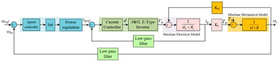
Figure 13.
Schematic of the control loop used to achieve the control tuning of the 3Φ5L E-Type Inverter.
The control tuning of the field-oriented structure is based on the procedure presented in [45]. Particularly, the current loop was tuned according to the transfer function (TF) in Equation (5), where it is possible to recognize four terms. The first term is the TF of the PI (Proportional-Integrator) controller Ri(s) where kpi and kii are respectively the proportional gain and the integral gain. The second term Ginv(s) is the TF of the inverter, which describes the converter behavior, where Kinv is the converter gain that depends on the modulation strategy, Td is the delay time of the converter equal to the switching period Tsw and Tdt is the delay time related to the dead-time of the converter. The third term GF(s) is the machine electrical model TF and the last term GLPi(s) is the TF of the low-pass filter, where ωfi is the filter cut-off frequency of the filter.
The speed loop was tuned considering that the bandwidth of the current loop is far enough from the desired speed loop crossover. In this way, the current control loop can be approximated with a unitary gain with no delay. The open-loop TF of the speed loop is written in Equation (6), where it is possible to recognize four terms: Rs(s) is the TF of the speed PI controller, Gi(s) is the current control TF, where ωc is the current loop bandwidth, GM(s) is the machine mechanical model TF and GLPs(s) is the low-pass filter TF, where ωfs is the cut-off frequency of the speed filter.
According to Equations (5) and (6), the current loop and the speed loop were tuned.
3.3. Control Tuning of DAB System
Figure 14 shows the block scheme of the control loop used to tune the DAB converter control structure. The tuning of the controller is based on the procedure presented in [46].
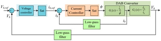
Figure 14.
Block scheme of the control loop used to achieve the control tuning of the DAB converter.
The open-loop TF of the current-loop GOLi(s) has three terms, as shown in Equation (7). GPIi(s) is the TF of the current controller and GLPi is the TF of the low-pass filter. Gi(s) is the TF from phase shift perturbation to the input current perturbation b, where VAB is the input voltage between the phase legs of the first full-bridge at a steady state, ϕ is the phase shift at a steady-state and LLK is the total leakage inductance of the transformer, LLK = L1 + (N1/N2)2L2.
Assuming that the crossover frequency of the current loop is greater than the crossover frequency of the voltage loop, the open-loop TF of the voltage loop is given in Equation (8).
Based on Equations (7) and (8) the current and voltage control loops of the DAB converter were tuned.
4. Experimental Results
Each sub-system, parts of the charging station, is accurately tested before any integration takes place. The switching frequency fsw of the 3Φ5L E-Type Inverter and Rectifier is set at 20 kHz, while the switching frequency fsw of the DAB is set at 40 kHz. The dead-time DT of the converters is set at 2 μs. Figure 15 and Figure 16 show the grid-tied converter waveforms when fully connected to the grid. The very low distortion related to the drawn current can be observed, which is due to an accurate control structure and properly designed power filter supported by the 5-level converter topology. The DC-bus voltage is set at 800 V in Figure 15 and the modulation depth M0 of the converter is equal to 0.8. As it can be seen from Figure 15, the fundamental component (yellow waveform) of the phase-to-neutral switching voltage ua(sw) (green waveform) is a pure sinusoidal waveform. The quality of the AC voltage waveforms is improving thanks to the nine voltage levels. Furthermore, given that the phase current ripple strongly depends on the number of voltage levels [47], having nine voltage levels helps to reduce the current ripple and improve the quality of the current. In fact, the grid current waveform (magenta track) is almost a pure sinusoidal waveform. The DC-bus voltage is kept constant at 600 V in Figure 16 and the modulation depth M0 of the converter is close to 1.
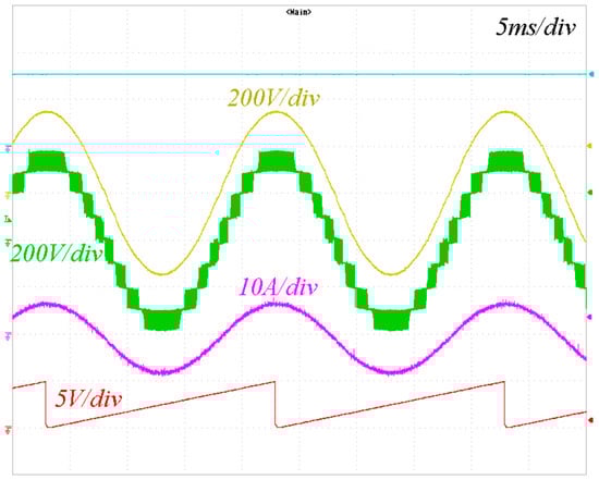
Figure 15.
Grid side converter waveforms: fundamental component (yellow track), phase-to-neutral switching voltage ua(sw) (green track), grid current ia (magenta track), estimated grid angle (red track).
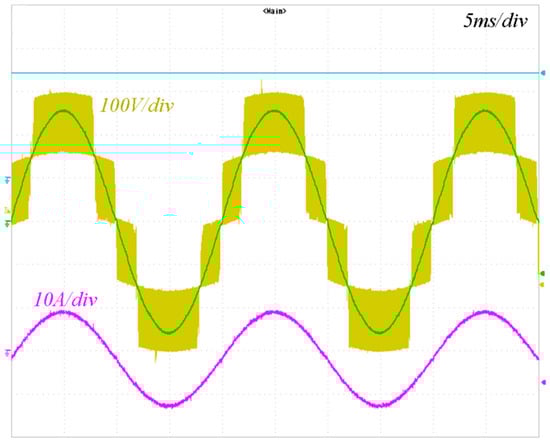
Figure 16.
Grid side converter waveforms: leg-to-neutral switching voltage ua1(sw) before the output power filter (yellow track), fundamental component (green track), injected phase current (magenta track).
The leg-to-neutral switching voltage ua1(sw) (see the label of Figure 4) shows five voltage levels as highlighted in yellow in Figure 16. Thus, the voltage waveform across the single-leg shows five voltage levels ua1(sw), while the voltage across the single-phase ua(sw) shows nine voltage levels thanks to the use of the interleaving technique [27,48]. Figure 17 illustrates the normalized harmonic spectrum of the AC phase current ia. The amplitude is normalized with respect to the fundamental. As can be seen, the harmonics 5, 7, 9, and 11 are relatively high due to dead-time DT equal to 2 μs. The THDi estimated up to the 50th order is close to 4.7%. Those tests were carried out by charging the battery on-board the vehicle directly from the electrical grid without the power boost provided by the flywheel. During the same test, waveforms related to the DC–DC DAB converter were collected and this is shown in Figure 18.
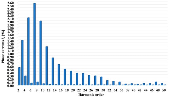
Figure 17.
Harmonic spectrum of the electrical machine phase currents ia.
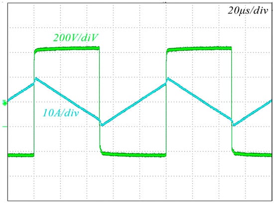
Figure 18.
DAB transformer current and applied voltage.
Flywheel energy storage system was tested and results are shown in Figure 19 for steady-state operation. In this condition, the DC-bus voltage is kept constant at 600 V and the modulation depth M0 of the converter is close to 1. Here too, the leg-to-neutral switching voltage uu1(sw) (magenta track) shows five voltage levels which helps to improve the quality voltage and current waveforms. Electrical machine phase currents and electrical flux position are clearly illustrating the correctness of the control system.
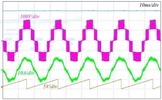
Figure 19.
Flywheel side converter waveforms during charging: leg-to-neutral switching voltage uu1(sw) (magenta track) before the ICT, fundamental component (extracted), electrical machine phase currents (green track) and angular flux position (red track).
5. Conclusions
This paper describes the main components of a multi-input charging station, which has a reduced impact on the public electrical grid due to local flywheel energy storage systems. High-efficiency power converter topologies were selected for both the grid-tied AC–DC converter and the flywheel inverter. As illustrated, the proposed multilevel converter configurations allowed us to strongly reduce the size and cost of the required AC filters to fulfill the grid connection standards. The results illustrate the effectiveness of the solution which could help the penetration of zero-emission vehicles especially for public transportation applications, where the mission profile is in general well known.
Author Contributions
Conceptualization, L.S.; methodology, A.L., F.O., M.d.B.; software, F.O. and M.d.B.; validation, F.O.; formal analysis, F.O., M.d.B. and A.L.; investigation, F.O.; resources, L.S., A.L.; data curation, F.O. and M.d.B.; writing—original draft preparation, F.O. and M.d.B.; writing—review and editing A.L., and L.S.; visualization, M.d.B.; supervision, L.S., and A.L.; project administration, L.S.; funding acquisition, L.S., and A.L. All authors have read and agreed to the published version of the manuscript.
Funding
This research activity was funded by “Ricerca di Sistema”, grant number PAR-2019. The prototype of DAB converter was supported by the Regione Lazio of Italy under Grant “Progetto di Gruppo di Ricerca finanziato ai sensi della L.R. Lazio 13/08”.
Acknowledgments
The Authors are thankful to “Sky Research doo” for building the prototype of the multilevel converters including the power filter used in the experimental campaign (miodrag@sky-research.com, dragan@sky-research.com).
Conflicts of Interest
The authors declare no conflict of interest. The funders had no role in the design of the study; in the collection, analyses, or interpretation of data; in the writing of the manuscript, or in the decision to publish the results.
References
- Halilcevic, S.S.; Georgilakis, P.S. How and Why the Batteries in the Sectors of Photovoltaics and Electric Vehicles Could Have Impact on the Society. IEEE Milan Power Tech. 2019, 1–6. [Google Scholar] [CrossRef]
- Said, D.; Mouftah, H.T. A Novel Electric Vehicles Charging/Discharging Management Protocol Based on Queuing Model. IEEE Trans. Intell. Veh. 2020, 5, 100–111. [Google Scholar] [CrossRef]
- Liu, X. Dynamic Response Characteristics of Fast Charging Station-EVs on Interaction of Multiple Vehicles. IEEE Access 2020, 8, 42404–42421. [Google Scholar] [CrossRef]
- Moradzadeh, M.; Abdelaziz, M.M.A. A New MILP Formulation for Renewables and Energy Storage Integration in Fast Charging Stations. IEEE Trans. Transp. Electrif. 2020, 6, 181–198. [Google Scholar] [CrossRef]
- Jayakumar, A.; Chalmers, A.; Lie, T. Review of prospects for adoption of fuel cell electric vehicles in New Zealand. IET Electr. Syst. Transp. 2017, 7, 259–266. [Google Scholar] [CrossRef]
- Shakeel, F.M.; Malik, O.P. Vehicle-To-Grid Technology in a Micro-grid Using DC Fast Charging Architecture. In Proceedings of the 2019 IEEE Canadian Conference of Electrical and Computer Engineering (CCECE), Edmonton, AB, Canada, 5–8 May 2019; IEEE: New York, NY, USA, 2019; pp. 1–4. [Google Scholar]
- Amanor-Boadu, J.M.; Abouzied, M.A.; Sanchez-Sinencio, E. An Efficient and Fast Li-Ion Battery Charging System Using Energy Harvesting or Conventional Sources. IEEE Trans. Ind. Electron. 2018, 65, 7383–7394. [Google Scholar] [CrossRef]
- Yao, L.W.; Aziz, J.A.; Kong, P.Y.; Idris, N.R.N.; Alsofyani, I.M. Modeling of lithium titanate battery for charger design. In Proceedings of the 2014 Australasian Universities Power Engineering Conference (AUPEC), Perth, Australia, 28 September–1 October 2014; IEEE: New York, NY, USA, 2014; pp. 1–5. [Google Scholar]
- Nadeem, F.; Hussain, S.M.S.; Tiwari, P.K.; Goswami, A.K.; Ustun, T.S. Comparative Review of Energy Storage Systems, Their Roles, and Impacts on Future Power Systems. IEEE Access 2019, 7, 4555–4585. [Google Scholar] [CrossRef]
- Pei Yulong, A.; Cavagnino, S.; Vaschetto, C.F.; Tenconi, A. Flywheel energy storage systems for power systems ap-plication. In Proceedings of the 2017 6th International Conference on Clean Electrical Power (ICCEP), Santa Margherita Ligure, Liguria, Italy, 27–29 June 2017; pp. 492–501. [Google Scholar]
- Krishna, K.S.; Vijayasree, G. Fast Charging Stations Supported By Flywheel Energy Storage Systems. In Proceedings of the 2020 IEEE 5th International Conference on Computing Communication and Automation (ICCCA), Galgotias University, Grater Noida, India, 30–31 October 2020; IEEE: New York, NY, USA, 2020; pp. 109–113. [Google Scholar]
- Iyer, V.M.; Gulur, S.; Gohil, G.; Bhattacharya, S. An Approach towards Extreme Fast Charging Station Power Delivery for Electric Vehicles with Partial Power Processing. IEEE Trans. Ind. Electron. 2020, 67, 8076–8087. [Google Scholar] [CrossRef]
- Tu, H.; Feng, H.; Srdic, S.; Lukic, S. Extreme Fast Charging of Electric Vehicles: A Technology Overview. IEEE Trans. Transp. Electrif. 2019, 5, 861–878. [Google Scholar] [CrossRef]
- Ortenzi, F.; Pasquali, M.; Prosini, P.P.; Lidozzi, A.; Di Benedetto, M. Design and Validation of Ultra-Fast Charging Infra-structures Based on Supercapacitors for Urban Public Transportation Applications. Energies 2019, 12, 2348. [Google Scholar] [CrossRef]
- Jiang, W.; Yu, F.; Lin, Z.; Wu, G.; Chen, H.; Hashimoto, S. Analysis and design of power management scheme for an on-board solar energy storage system. In Proceedings of the 2014 International Power Electronics Conference (IPEC-Hiroshima 2014–ECCE ASIA), Hiroshima, Japan, 18–21 May 2014; IEEE: New York, NY, USA, 2014; pp. 1471–1475. [Google Scholar]
- Obando, A.F.; Herrera, V.I.; Gaztanaga, H.; Gallardo, G.; Nieva, T.; Varela, M. Optimization Methodology of Infrastruc-ture and Onboard Energy Storage System for Cost-Reduction in Tramway Lines Design. In Proceedings of the 2017 IEEE Vehicle Power and Pro-pulsion Conference (VPPC), Belfort, France, 11–14 December 2017; pp. 1–7. [Google Scholar]
- Kampeerawar, W.; Koseki, T.; Zhou, F. Efficient Urban Railway Design integrating Train Scheduling, Onboard Energy Storage, and Traction Power Management. In Proceedings of the 2018 International Power Electronics Conference (IPEC-Niigata 2018–ECCE Asia), Niigata, Japan, 20–24 May 2018; IEEE: New York, NY, USA, 2018; pp. 3257–3264. [Google Scholar]
- Mei, J.; Cheng, E.K.W.; Fong, Y.C. Lithium-titanate battery (LTO): A better choice for high current equipment. In Proceedings of the 2016 International Symposium on Electrical Engineering (ISEE), Hong Kong, China, 14 December 2016; IEEE: New York, NY, USA, 2017; pp. 1–4. [Google Scholar]
- Cignini, F.; Genovese, A.; Ortenzi, F.; Alessandrini, A.; Berzi, L.; Pugi, L.; Barbieri, R. Experimental Data Comparison of an Electric Minibus Equipped with Different Energy Storage Systems. Batteries 2020, 6, 26. [Google Scholar] [CrossRef]
- Ortenzi, F.; Andrenacci, N.; Pasquali, M.; Villante, C. On the Hybridization of Microcars with Hybrid UltraCapacitors and Li-Ion Batteries Storage Systems. Energies 2020, 13, 3230. [Google Scholar] [CrossRef]
- Liu, Y.; Tang, Y.; Shi, J.; Shi, X.; Deng, J.; Gong, K. Application of Small-Sized SMES in an EV Charging Station With DC Bus and PV System. IEEE Trans. Appl. Supercond. 2014, 25, 1–6. [Google Scholar] [CrossRef]
- Sun, B.; Dragičević, T.; Freijedo, F.D.; Vasquez, J.C.; Guerrero, J.M. A Control Algorithm for Electric Vehicle Fast Charg-ing Stations Equipped with Flywheel Energy Storage Systems. IEEE Trans. Power Electron. 2016, 31, 6674–6685. [Google Scholar] [CrossRef]
- Stroe, A.; Stroe, D.; Knap, V.; Swierczynski, M.; Teodorescu, R. Accelerated Lifetime Testing of High-Power Lithium Titan-ate Oxide Batteries. In Proceedings of the 2018 IEEE Energy Conversion Congress and Exposition (ECCE), Portland, OR, USA, 23–27 September 2018; pp. 3857–3863. [Google Scholar]
- Lu, F.; Liu, D.; Liu, Y.; Li, Z.; Jiang, Q.; Chen, Y. A Study on Low-Temperature Model Parameter Identification of LTO Bat-tery by Cuckoo Search. In Proceedings of the 2020 15th IEEE Conference on Industrial Electronics and Applications (ICIEA), Kristiansand, Norway, 9–13 November 2020; pp. 490–494. [Google Scholar]
- Zhang, X.; Peng, H.; Wang, H.; Ouyang, M. Hybrid Lithium Iron Phosphate Battery and Lithium Titanate Battery Systems for Electric Buses. IEEE Trans. Veh. Technol. 2017, 67, 956–965. [Google Scholar] [CrossRef]
- Di Benedetto, M.; Solero, L.; Crescimbini, F.; Lidozzi, A.; Grbovic, P.J. 5-Level E-type back to back power converters—A new solution for extreme efficiency and power density. In Proceedings of the 2017 13th Conference on Ph.D. Research in Microelectronics and Electronics (PRIME), Taormina, Italy, 12–15 June 2017; IEEE: New York, NY, USA, 2017; pp. 341–344. [Google Scholar]
- Di Benedetto, M.; Lidozzi, A.; Solero, L.; Crescimbini, F.; Grbovic, P.J. Low Volume and Low Weight 3-Phase 5-Level Back to Back E-Type Converter. IEEE Trans. Ind. Appl. 2019, 55, 7377–7388. [Google Scholar] [CrossRef]
- Deng, F.; Lu, Y.; Liu, C.; Heng, Q.; Yu, Q.; Zhao, J. Overview on submodule topologies, modeling, modulation, control schemes, fault diagnosis, and tolerant control strategies of modular multilevel converters. Chin. J. Electr. Eng. 2020, 6, 1–21. [Google Scholar] [CrossRef]
- Di Benedetto, M.; Lidozzi, A.; Solero, L.; Crescimbini, F.; Grbovic, P.J. Five-level back to back E-Type converter for high speed gen-set applications. In Proceedings of the IECON 2016—42nd Annual Conference of the IEEE Industrial Electronics Society, Florence, Italy, 24–27 October 2016; IEEE: New York, NY, USA, 2016; pp. 3409–3414. [Google Scholar]
- Di Benedetto, M.; Lidozzi, A.; Solero, L.; Grbovic, P.J.; Bifaretti, S. ISOP DC-DC converters equipped 5-level unidirectional T-Rectifier for aerospace applications. In Proceedings of the 2015 IEEE Energy Conversion Congress and Exposition (ECCE), Montreal, Canada, 20–24 September 2015; IEEE: New York, NY, USA, 2015; pp. 1694–1700. [Google Scholar]
- Liu, G.; Li, K.; Wang, Y.; Luo, H.; Luo, H. Recent advances and trend of HEV/EV-oriented power semiconductors—An overview. IET Power Electron. 2020, 13, 394–404. [Google Scholar] [CrossRef]
- Kucka, J.; Karwatzki, D.; Mertens, A. Enhancing the Reliability of Modular Multilevel Converters Using Neutral Shift. IEEE Trans. Power Electron. 2017, 32, 8953–8957. [Google Scholar] [CrossRef]
- Di Benedetto, M.; Lidozzi, A.; Solero, L.; Crescimbini, F.; Grbovic, P.G. Low-Frequency State-Space Model for the Five-Level Unidirectional T-Rectifier. IEEE Trans. Ind. Appl. 2017, 53, 1127–1137. [Google Scholar] [CrossRef]
- Di Benedetto, M.; Lidozzi, A.; Solero, L.; Crescimbini, F.; Grbovic, P.J. Small-Signal Model of the Five-Level Unidirectional T-Rectifier. IEEE Trans. Power Electron. 2017, 32, 5741–5751. [Google Scholar] [CrossRef]
- Bal, S.; Yelaverthi, D.B.; Rathore, A.K.; Srinivasan, D. Improved Modulation Strategy Using Dual Phase Shift Modulation for Active Commutated Current-Fed Dual Active Bridge. IEEE Trans. Power Electron. 2018, 33, 7359–7375. [Google Scholar] [CrossRef]
- La Mendola, M.; Di Benedetto, M.; Lidozzi, A.; Solero, L.; Bifaretti, S. Four-Port Bidirectional Dual Active Bridge Converter for EVs Fast Charging. In Proceedings of the 2019 IEEE Energy Conversion Congress and Exposition (ECCE), Baltimore, MD, USA, 29 September–3 October 2019; IEEE: New York, NY, USA, 2019; pp. 1341–1347. [Google Scholar]
- Nguyen, D.-D.; Yukita, K.; Katou, A.; Yoshida, S. Design Optimization of a Three-Phase Dual-Active-Bridge Converter for Charging Stations. In Proceedings of the 2019 IEEE Vehicle Power and Propulsion Conference (VPPC), Hanoi, Vietnam, 14–17 October 2019; pp. 1–6. [Google Scholar]
- Di Benedetto, M.; Lidozzi, A.; Solero, L.; Crescimbini, F.; Bifaretti, S. Hardware design of SiC-based Four-Port DAB Con-verter for Fast Charging Station. In Proceedings of the 2020 IEEE Energy Conversion Congress and Exposition (ECCE), Detroit, MI, USA, 11–15 October 2020; pp. 1231–1238. [Google Scholar]
- Gill, L.; Ikari, T.; Kai, T.; Li, B.; Ngo, K.; Dong, D. Medium Voltage Dual Active Bridge Using 3.3 kV SiC MOSFETs for EV Charging Application. In Proceedings of the 2019 IEEE Energy Conversion Congress and Exposition (ECCE), Baltimore, MD, USA, 29 September–3 October 2019; IEEE: New York, NY, USA, 2019; pp. 1237–1244. [Google Scholar]
- Amamra, S.-A.; Marco, J. Vehicle-to-Grid Aggregator to Support Power Grid and Reduce Electric Vehicle Charging Cost. IEEE Access 2019, 7, 178528–178538. [Google Scholar] [CrossRef]
- Ghosh, A.; Aggarwal, V. Menu-Based Pricing for Charging of Electric Vehicles with Vehicle-to-Grid Service. IEEE Trans. Veh. Technol. 2018, 67, 10268–10280. [Google Scholar] [CrossRef]
- Bifaretti, S.; Lidozzi, A.; Solero, L.; Crescimbini, F. Anti-Islanding Detector Based on a Robust PLL. IEEE Trans. Ind. Appl. 2014, 51, 398–405. [Google Scholar] [CrossRef]
- Lidozzi, A.; Solero, L.; Crescimbini, F. Adaptive Direct-Tuning Control for Variable-Speed Diesel-Electric Generating Units. IEEE Trans. Ind. Electron. 2011, 59, 2126–2134. [Google Scholar] [CrossRef]
- Lidozzi, A.; Di Benedetto, M.; Bifaretti, S.; Solero, L.; Crescimbini, F. Resonant Controllers with Three Degrees of Freedom for AC Power Electronic Converters. IEEE Trans. Ind. Appl. 2015, 51, 4595–4604. [Google Scholar] [CrossRef]
- Lidozzi, A.; Serrão, V.; Solero, L.; Crescimbini, F.; Di Napoli, A. Direct Tuning Strategy for PMSM Drives. IEEE Ind. Appl. Soc. Annu. Meet. 2008, 1–7. [Google Scholar] [CrossRef]
- Solero, L.; Lidozzi, A.; Pomilio, J. Design of multiple-input power converter for hybrid vehicles. Ninet. Annu. IEEE Appl. Power Electron. Conf. Expo. APEC 2004, 20, 1007–1016. [Google Scholar] [CrossRef]
- Grbovic, P.G.; Lidozzi, A.; Solero, L.; Crescimbini, F. Five-Level Unidirectional T-Rectifier for High-Speed Gen-Set Appli-cations. IEEE Trans. Ind. Appl. 2016, 52, 1642–1651. [Google Scholar] [CrossRef]
- Di Benedetto, M.; Lidozzi, A.; Solero, L.; Crescimbini, F.; Grbovic, P.J. Design of High-Power Density Interleaved 3-Phase 5-Level E-Type Back-to-Back Converter. In Proceedings of the 2020 IEEE Energy Conversion Congress and Exposition (ECCE), Detroit, MI, USA, 11–15 October 2020; IEEE: New York, NY, USA, 2020; pp. 3957–3964. [Google Scholar]
Publisher’s Note: MDPI stays neutral with regard to jurisdictional claims in published maps and institutional affiliations. |
© 2021 by the authors. Licensee MDPI, Basel, Switzerland. This article is an open access article distributed under the terms and conditions of the Creative Commons Attribution (CC BY) license (http://creativecommons.org/licenses/by/4.0/).