Article

Innovative and Highly Integrated Modular Electric Drivetrain

1
Institute for Automotive Engineering (ika), RWTH Aachen University, 52056 Aachen, Germany
2
Department of Mechanics and Maritime Sciences, Chalmers University of Technology, 41296 Gothenburg, Sweden
3
Electromechanics and Power Electronics Group, Eindhoven University of Technology, 5612 AZ Eindhoven, The Netherlands
4
BRUSA Elektronik AG, 9466 Sennwald, Switzerland
5
Commissariat à l’énergie atomique et aux énergies alternatives–CEA, 38054 Grenoble Cedex, France
6
Punch Powertrain, 3800 Sint-Truiden, Belgium
7
MAHLE ZG Transmissions GmbH, 85386 Eching-Dietersheim, Germany
8
Simulations and Test Solutions – Siemens Industry Software, S.A.S, 69006 Lyon, France
*
Author to whom correspondence should be addressed.
World Electr. Veh. J. 2019, 10(4), 89; https://doi.org/10.3390/wevj10040089
Submission received: 11 October 2019 / Revised: 3 December 2019 / Accepted: 5 December 2019 / Published: 11 December 2019

Abstract

:
A highly integrated electric drivetrain module with 157 kW peak power is presented, which incorporates novel technologies in the field of electric machines, power electronics and transmissions: 1. High-speed electric machine with six phases and injection mould polymer-bonded magnets; 2. High-ratio dual-speed transmission with double planetary gear set (Ravigneaux gear set); 3. Gallium nitride (GaN) power electronics with winding reconfiguration feature.The combination of these components in one single housing makes the drive module flexible to integrate and to combine with conventional or alternative propulsion technologies, thus allowing various hybrid and electric drivetrain topologies. All technologies are selected in accordance with mass production potential and can therefore have a high impact on the automotive market in the future. Currently, the drive module is under development; the first models will be assembled in winter 2019. The integration into a demonstrator vehicle in 2020 will prove the potential of many new technologies and the suitability for the automotive market.

1. Introduction

The electrification of passenger cars and light-duty vehicles—which are still responsible for around 20% of Europe’s greenhouse gas emissions [1]—will have an enormous effect on the reduction of greenhouse gas emissions. Additionally, pollutant-free air in dense urban areas is possible with electrified propulsion [2,3]. However, the maturity of electric drives needs a final push for better performance and efficiency so that battery capacity can be saved and driving range can be increased. Combined with a cost reduction, a massive adoption of such transport in Europe and worldwide can be generated [4]. This paper presents a new generation of a modular electric drive module, which can be used for various configurations of Full and Hybrid Electric Vehicles. The focus is on cost reduction, low environmental impact, efficiency, and mass manufacturing readiness. The multiphase electric machine based on permanent magnets will be combined with the latest Gallium Nitride (GaN) power switches, advanced control with higher fault tolerance, and cooling features with reduced dimensions and a higher efficiency. It will be linked with a performant two-speed transmission, also adapting new regenerative braking strategies. The development takes industrial- and user requirements into account as well as environmental impacts through a life cycle analysis, to gear the activities towards a full vehicle design approach and the realization of each component and the complete powertrain. The project gathers nine cutting-edge partners from the fields of automotive, power electronics, transmissions and electric motors including three research centers, three Tier-1 suppliers and “Small and Medium Entrepreneurs”.

2. Results

2.1. Permanent Magnet Hybrid Synchronous Machine

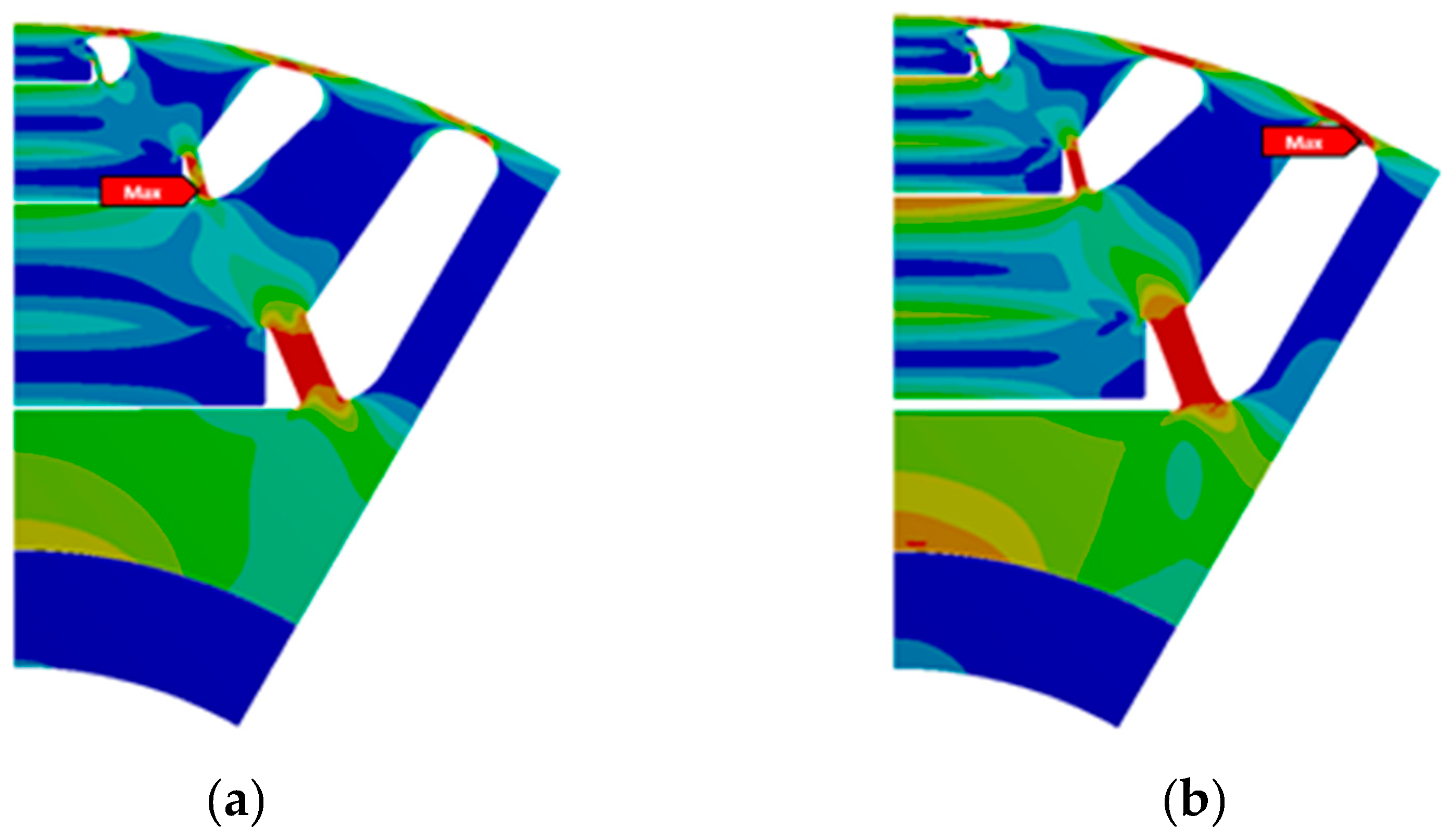
2.1.1. Machine Design

In order to achieve very high power densities even with low available current and voltage, sophisticated electromagnetic designs are required. Additionally, the automotive market has strong requirements, adding additional effort to the design of a motor which is safe and strong at the same time [5]. To meet these challenges, the Hybrid Synchronous Motor (HSM) was invented a few years ago, which is an evolution of the internal permanent magnet motor (IPM) [6]. It is called Hybrid, because it utilizes a combination of reluctance and electromagnetic torque; it is sometimes also referred to as a “permanent magnet assisted synchronous reluctance machine” (PMaSynRM). The torque production by these two effects is the reason why it is difficult to design this type of machine. Small changes in the geometry or materials influence both effects and therefore, can have a significant impact on performance, torque ripple, efficiency, power factor, controllability, demagnetisation and more.
The main goal for the EM development was to save more than 50% magnet mass compared to existing permanent magnet synchronous machine (PMSM) with similar power, to reduce the active weight and to improve the efficiency. As a reference, the electric motor of the BMWi3 is considered, since it is a state of the art motor which has proven its matureness on the road. Its specifications together with the developed motors are shown in Table 1.
Even though ferrite magnets have the lowest environmental impact among the available magnets, they were not selected, mainly due to the following reasons:
-
Since the current capability of the gallium nitride inverter is expected to be low, the missing torque through current must be compensated by highest power magnets.
-
Due to the high speeds of the rotor, the small rotor cross section does not provide sufficient space to design a mechanically stable rotor with a high mass of ferrite magnets (which would be needed in order to produce the same air gap flux as with NdFeB magnets).
-
Ferrite magnets of currently available grades are not sufficiently safe against demagnetization.
Many iterations were needed to satisfy all of the previously defined drive requirements. The resulting electric machine is a six-pole, six-phase HSM for high speeds up to 22,500 rpm. Since power is proportional to both speed and torque, the torque requirement for the motor is relatively low. For decent accelerations from 0 to 50 km/h of a C-class vehicle with the given gear ratio of 21.65, a max. torque of only 150 Nm is required. With this gear ratio and motor torque, the vehicle can accelerate from 0 to 50 km/h in around 3 s. As the required motor torque is comparatively low, the required phase current is also low, in this case only 225 A (rms) per phase. A challenge for high-speed motors is the centrifugal forces at the rotor which require mechanical stabilization and special rotor geometries to hold the permanent magnets in place [7]. The equivalent von-Mises stress of the rotor was tested at speeds higher than rated speeds. At an over-speed of 27,000 rpm (20% higher than rated speed), the stress does not exceed the material limit Figure 1b. Unfortunately, the injected magnet rotor cannot be shown here, since a patent for the design is pending.
The stator windings are made from a special wire type called “Formed Litz Wire” (FLW, Figure 2b). This wire type provides low DC resistance (similar to massive copper bars) and low AC resistance (similar to conventional Litz wires) at the same time [8]. FLW technology combined with the high-speed motor concept leads to a very low phase resistance and high continuous power, because a small motor also has short wires. Additionally, iron losses are reduced because of the low flux harmonic content, even if the motor speed is very high.
The project target torque of 150 Nm is surpassed from the simulations by 156 Nm at a current of 225 A (rms) and 320 VDC. Since the nominal speed will also be higher than expected (8650 rpm instead of 6600 rpm), the power at the new nominal speed rises to 141 kW. Above the nominal speed, the power does not drop, it rises again to more than 157 kW (213 hp) between 12,000 and 16,000 rpm. This is very impressive if we consider the low remanence flux density (Br) of only 0.75 T @ 25 °C, compared to sintered NdFeB magnets which are available with more than 1.4 T @ 25 °C. For this project, sintered magnets of the grade 45UH were chosen. These provide a good compromise between costs and energy density (BHmax of 374 kJ/m3) while at the same time being robust to demagnetization at high temperatures [9]. Due to the typically low temperature rating of Dy-free magnets, it is not possible to use them here with a sophisticated rotor design.
To achieve high levels of power with only 320 VDC and 225 A (rms), perfect magnetisation, optimal motor control and also very good mechanical design such as low friction bearings, a stiff shaft and many other intelligent features are needed. Furthermore, not only a strong and light motor is strived for; it is no less important to have a good efficiency. Simulations showed that with this high-speed drive, a peak efficiency of more than 97% can be realized (Figure 3). However, the key to saving energy and battery size is mainly not peak efficiency, but a high drive cycle efficiency. Since the majority of drive cycles demand only low power, the final HSM design was selected with a specific focus on low load efficiency. This helps to improve the overall energy consumption and to save battery capacity.

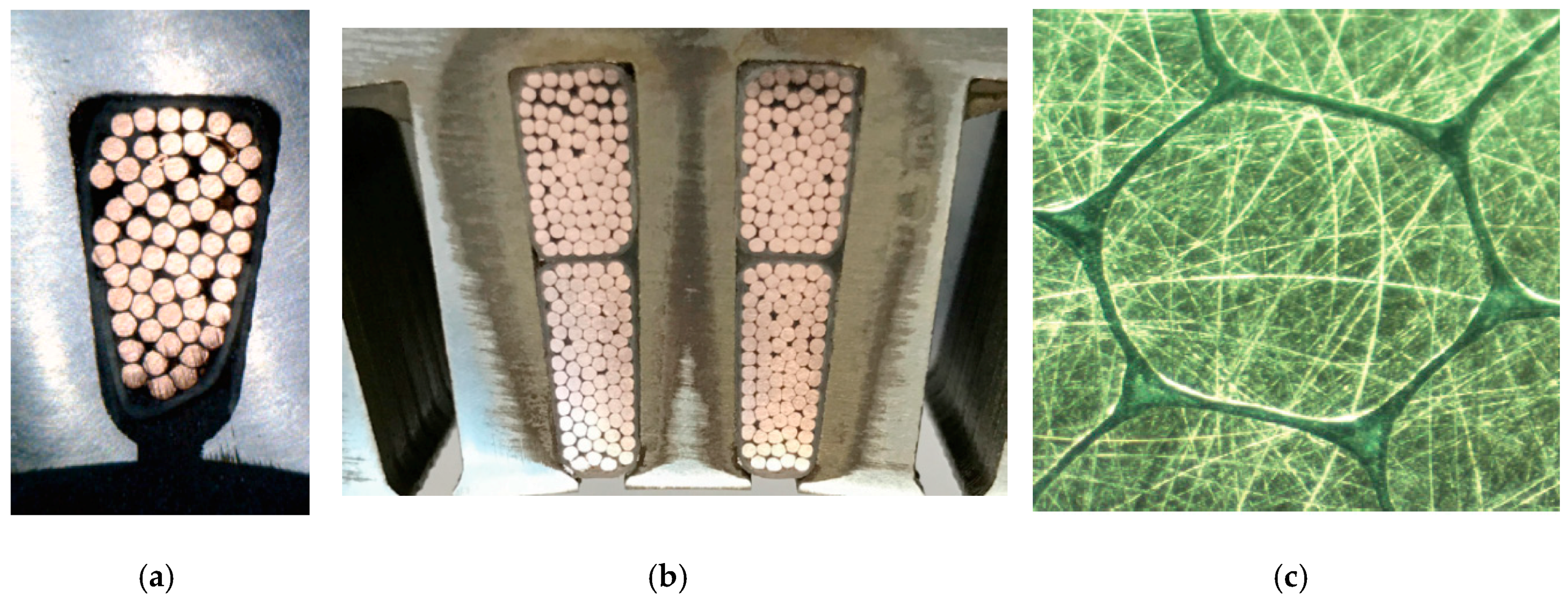
2.1.2. Magnet Injection Moulding

Injection moulding of polymer-bonded magnets in the rotor cavities instead of insertion of sintered magnets was identified as one of the possible ways to further reduce the content of critical raw materials in the motor. Unfortunately, bonded magnets have less remanence flux density (Br) than sintered magnets but they contain no heavy rare-earth (Dy and Tb which are more critical than Nd and whose price might raise more severely if a supply crisis were to occur) [10]. They also allow complete freedom in the shape of the magnets, yielding some magnetic optimization potential of the rotor. Furthermore, all 66 magnets of a rotor slice can be injected in one single step, which lowers the production effort.
As the mechanical strength of bonded magnets is lower than of sintered magnets (flexural strength 52 MPa vs. 285 MPa [9,10]), centrifugal forces are a serious issue. Hence, a mechanically stable rotor geometry was developed for which the calculated power and efficiency of this injected magnet rotor are comparable to the sintered magnet one. Magnetostatic finite-elements calculations were performed in order to design a magnetizer tool to produce the proper magnetic field in the rotor cavities during the injection process. The principle of magnetization of the permanent magnet material is illustrated in Figure 4a. A particular effort had to be made in order to comply magnetic requirements with mechanical constraints in the design of the mold: the magnetic field needs to be produced as homogeneously as possible in all the cavities simultaneously because injection must occur in all the magnetic poles at once in order to preserve the rotor integrity. The rotor also needs to be tightly maintained from all sides during the injection, but has to be released for extraction. A complete design of the mould has been issued (Figure 4b) and is now being realized. The main dimensions of the tool are 650 × 500 × 354 mm for a rotor segment with only 117 mm diameter and 30 mm height. First injection experiments in rotors are planned for the beginning of 2020.
With regards to materials, several grades of composites are available; the most suited one among about 10 available grades has been identified and injected to parallelepipedic samples (Figure 5) with an existing mold. Criteria for the choice of the 5SP-12ME grade were the following threefold: binder has to be stable at 150 °C (PPS better than PA), the remanence has to be high (mixture of SmFeN and NdFeB better than pure NdFeB), and the coercivity has to be sufficient (MF18P powder better than MF15P) [10]. This, combined with some rheological studies, gave some useful hints regarding injection parameters to achieve proper filling of the complex rotor cavities. The dependence of the magnet strength on the field intensity during injection was investigated experimentally in order to set to a proper field intensity target in the mold, allowing to set the dimensions of the magnetizing coils and in particular, the cooling system.

2.2. GaN Inverter

2.2.1. Advantages of Gallium Nitride Devices

The low-voltage Gallium Nitride (GaN) power device technology (650 V) provides a lot of advantages compared to its Silicon (Si) and Silicon Carbide (SiC) competitors [11,12]. In terms of performance, the Gallium Nitride devices have
  • an unrivalled switching performance with switching on/off in less than 10 ns,
  • a low package inductance,
  • a low on-resistance
  • and reduced switching losses: five times better than Si devices and two times better than SiC devices.
With these advantages, the switching frequency can be raised and hence, the size of passive components can be reduced: the inverter becomes smaller and more efficient at the same time.
The GaN technology is young and under ongoing development. As an example, the current capacity per die is still low: 60 A in 2017 and 120 A in 2019. In the framework of this research project, in order to fulfil power requirements, extensive work was done in developing a reliable parallelization of dies.

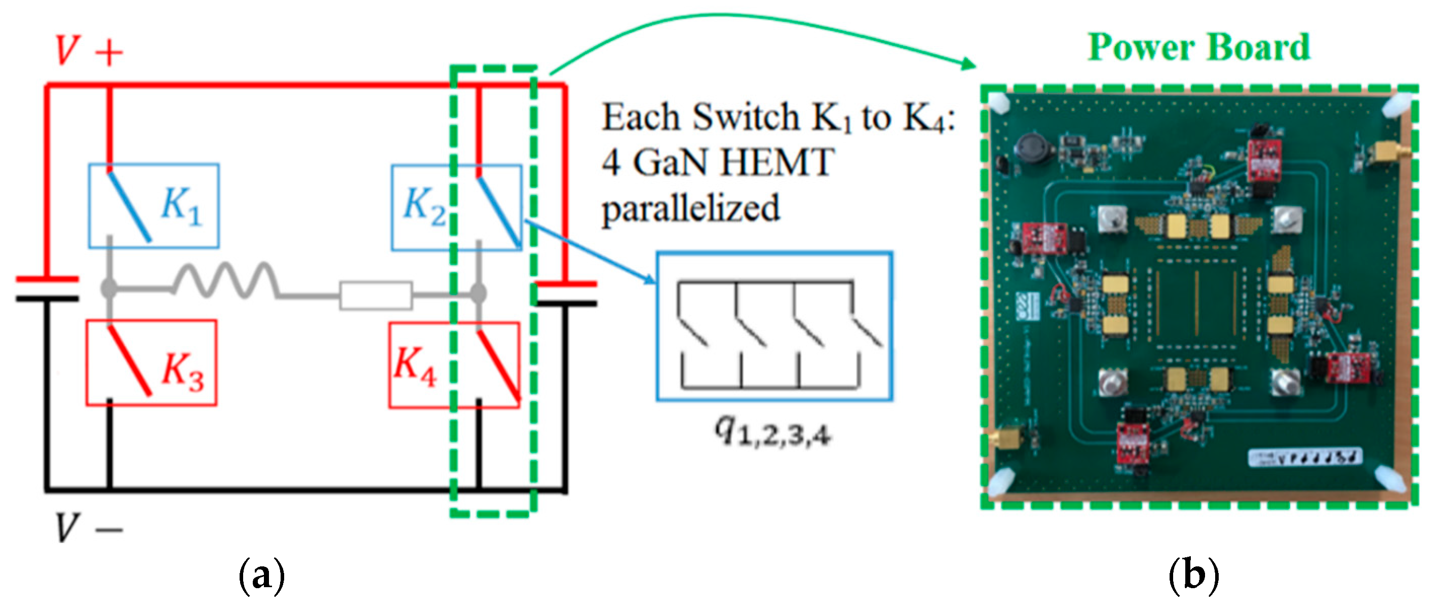
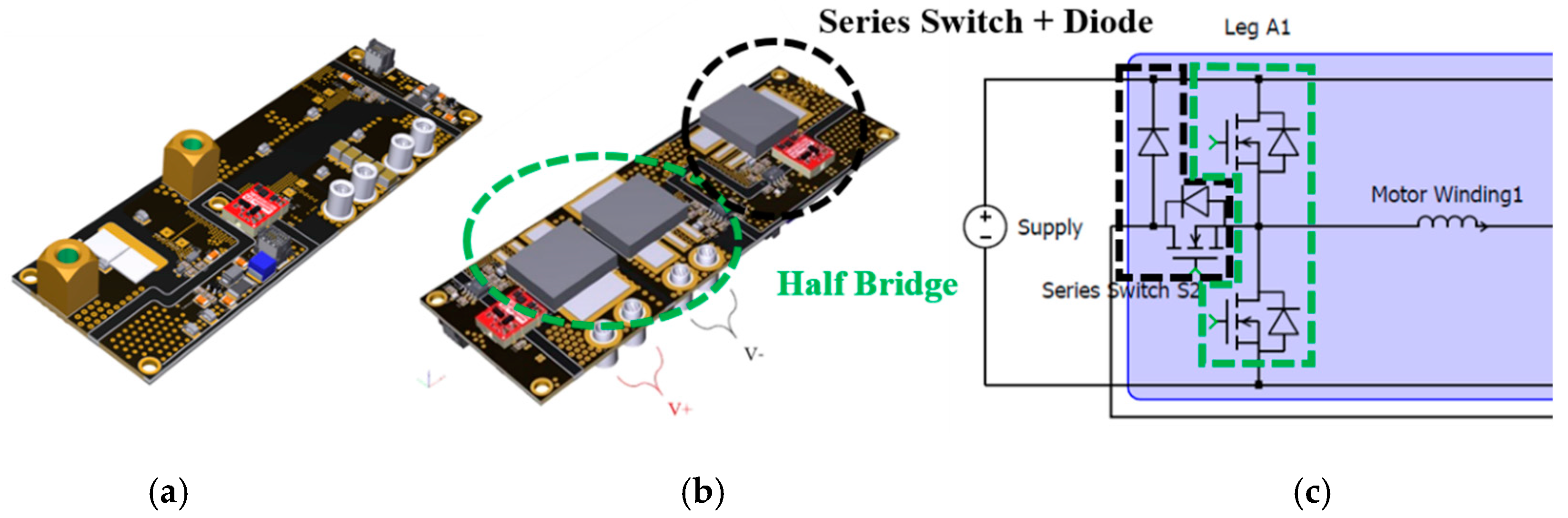
2.2.2. GaN Power Board Conception

In order to obtain the required torque of 150 Nm in the six-phase high-speed motor, a current of 225 A (rms) per phase is requested. Each phase is independently connected to a full bridge in which each of two switches is realized with four parallelized GaN devices, specified in [11]. The topology of the full bridge is depicted in Figure 6a with each switch (K1,2,3,4), realized by four GaN devices in parallel. A first power board prototype of one leg of the bridge is shown in Figure 6b.
Hardware development started with the parallelization of two devices. The experimental waveforms in Figure 7 show the results for two parallelized GaN devices with V DC = 300   V at a double pulse test with an inductive load ( L = 330   uH ,   i s a t = 200   A ). As shown, the switching of the two devices is synchronous, which is essential to maintain an equal current in the two of them. Moreover, oscillations on the DC bus at a frequency of approximately 1.2 MHz can be observed, which were induced by an exchange of reactive energy between the required decoupling capacitors.
The oscillations can be explained by the characterization of the circuit using a Bode plot shown in Figure 8. A resonance can be observed at 1.2 MHz, matching exactly the frequency of the oscillations. These oscillations were subsequently reduced by a better dimensioning of the decoupling and DC bus capacitors.
While the project progressed, higher power GaN devices became available and 650 V, 120 A GaN devices could be used for the second generation power boards. The power board was designed as shown in Figure 9a,b. The topology of the board is almost the same as on the prototype; only an extra power device was added, which acts as series switch (functionality explained in Section 2.2.3).

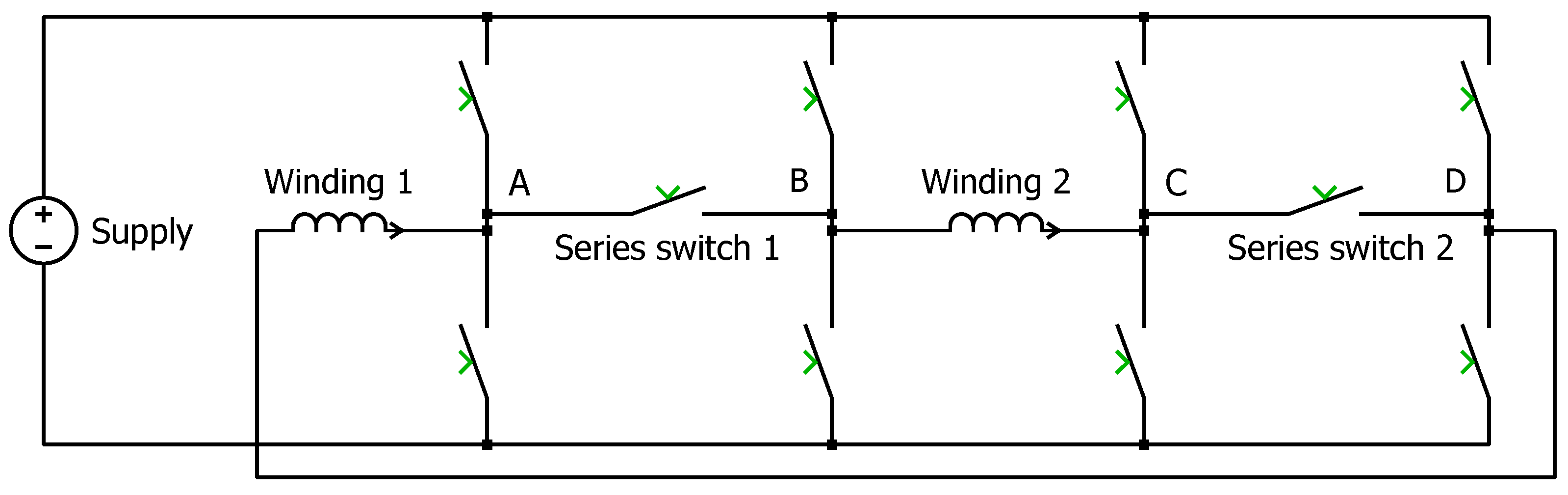
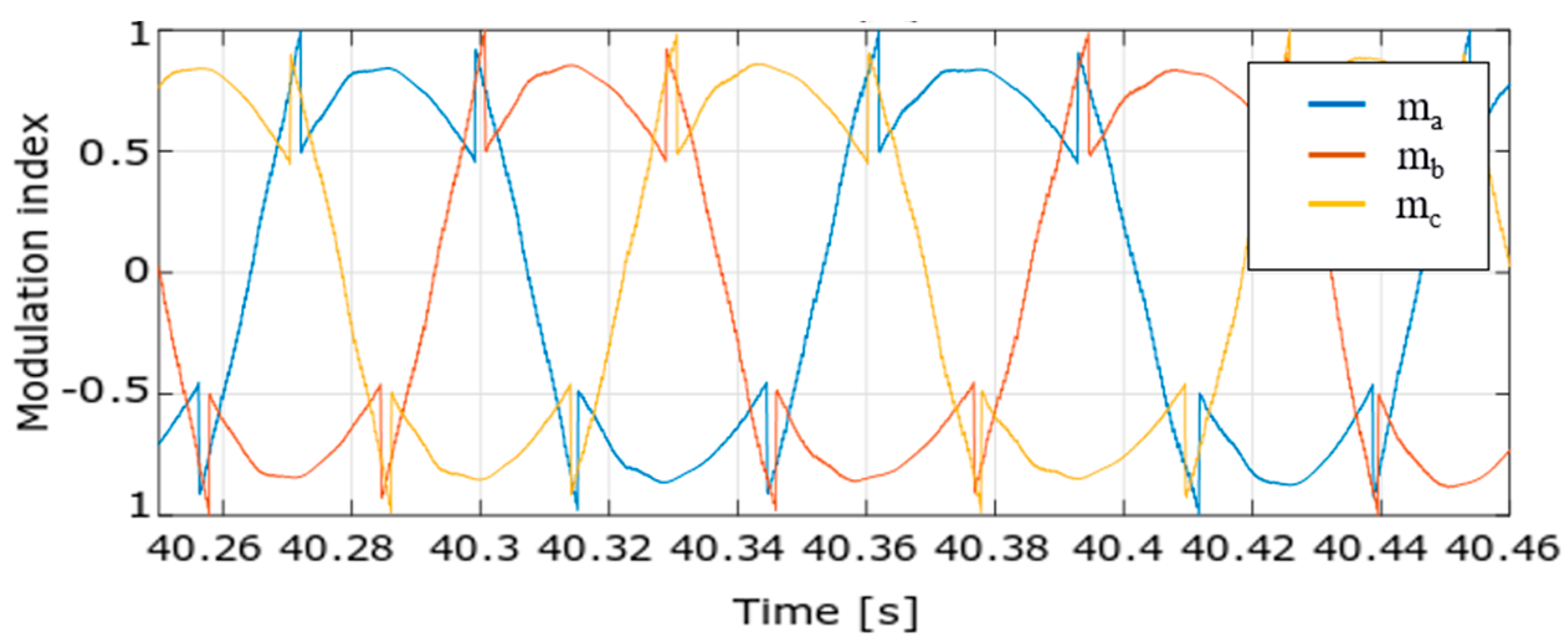
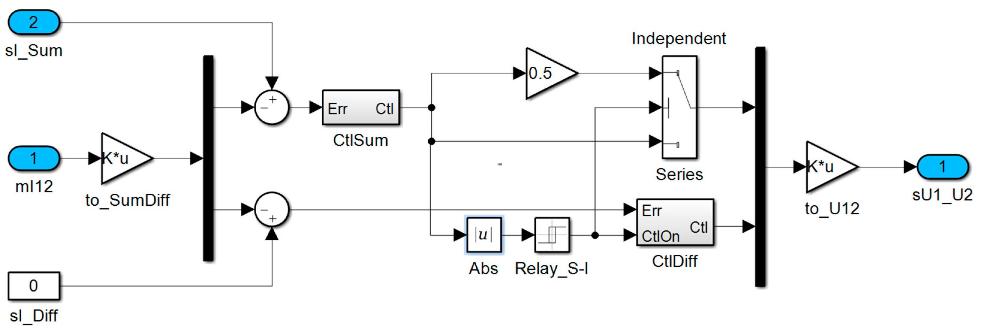
2.2.3. Series-independent Winding Reconfiguration

In this section, a six-winding EM is used to explain the winding reconfiguration principle. Its windings are independent of each other, meaning that there is no star point, which enables a free choice of the machine winding configuration. Furthermore, a fault tolerant operation (with reduced power) is possible [13]. Figure 10 shows the implementation for one of the three phases, i.e., for two windings.
The two windings are connected to the supply by means of a switch matrix, comprising two full bridges and two series switches, depicted as contactors, and each machine winding is represented by a single inductor. The matrix is able to interconnect the windings in series or to connect each winding independently to the supply. In the series configurations, either series switch 1 or 2 is closed. Hence, the current in the series-connected windings can be controlled by means of two phase legs only, which is advantageous with respect to switching losses in the phase legs.
In the independent configurations, the winding currents are controlled individually. Nevertheless, due to the symmetric construction of the motor, both currents will, in principle, be controlled to the same value.
In a first implementation of this concept [14], a single series switch was used, and the reconfiguration was applied depending on the actual speed of the motor. However, this way of operating has to include a certain margin for varying supply voltage, stator impedance, and magnetic field strength in the machine. Additionally, once the independent configuration is used, it applies during a complete cycle of the voltage wave of the machine phase, although in the sections close to a zero crossing, the series configuration could still be used. Finally, with only a single series switch available, the loading of the four phase legs is asymmetric; as always, the same two legs were disabled in the series operation. Thus, in order to spread the losses more evenly over the phase legs, a second series switch was introduced [15].
Therefore, in the present work, it was decided to extend the reconfiguration concept: when possible, a series configuration was used, and only where necessary (starting at the peak of the voltage wave applied to a machine phase), the windings were controlled independently. Moreover, in order to spread the losses more evenly over the phase legs, a second series switch was introduced, as shown in Figure 10. As an ultimate refinement, the PWM patterns in the independent configuration were shifted 180 degrees with respect to each other, thereby minimizing the net torque ripple in the machine.
Due to the reconfiguration, the system order changes during operation: in the series mode, only one current per phase needs to be controlled, but in the independent mode, two currents have to be regulated. The resulting control method for one phase is depicted in Figure 11. As shown, the switching on/off of the Difference Current controller (by definition zero in the series configuration) is governed by a binary signal derived from the output of the Sum Current controller (the desired winding current): once the demanded voltage for the series connection becomes too large in view of the DC link voltage, the configuration is changed to independent, the Difference Current controller is enabled, and the controller gain halved in order to avoid a transient in its output due to the changed load configuration.
To control all three phases, the sum currents were transformed to the d-q-0 frame by means of the Park transformation. For brevity, this approach, which is quite standard for the control of three-phase machines, is not detailed further in this paper.

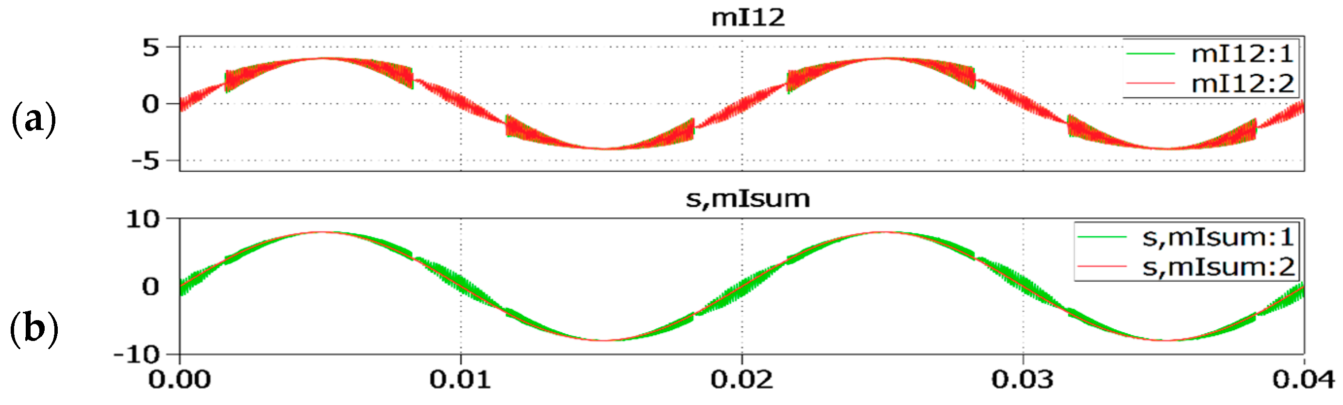
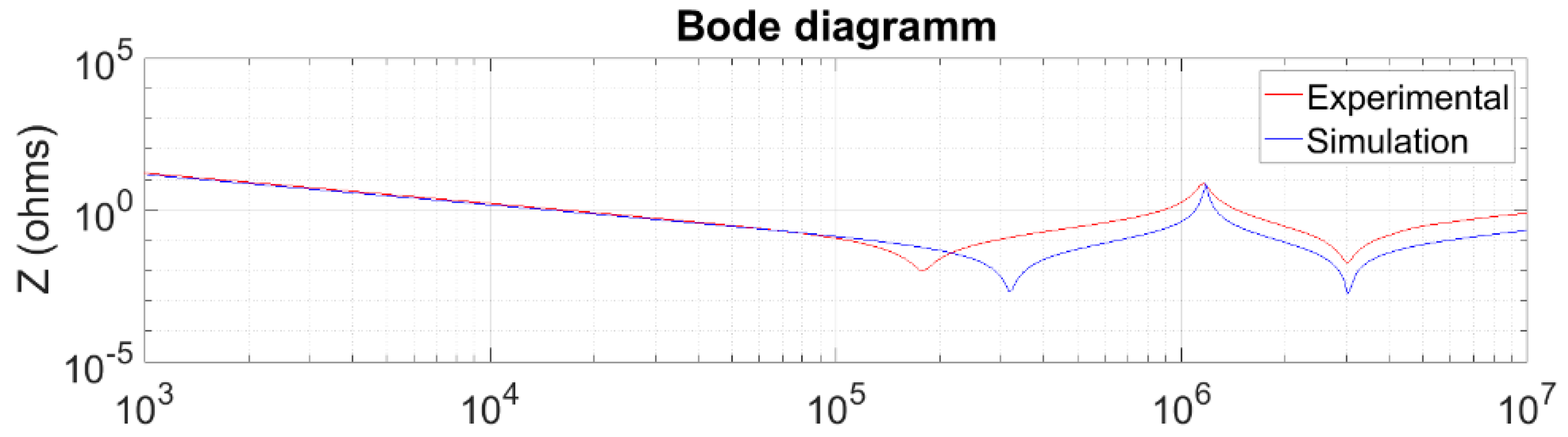
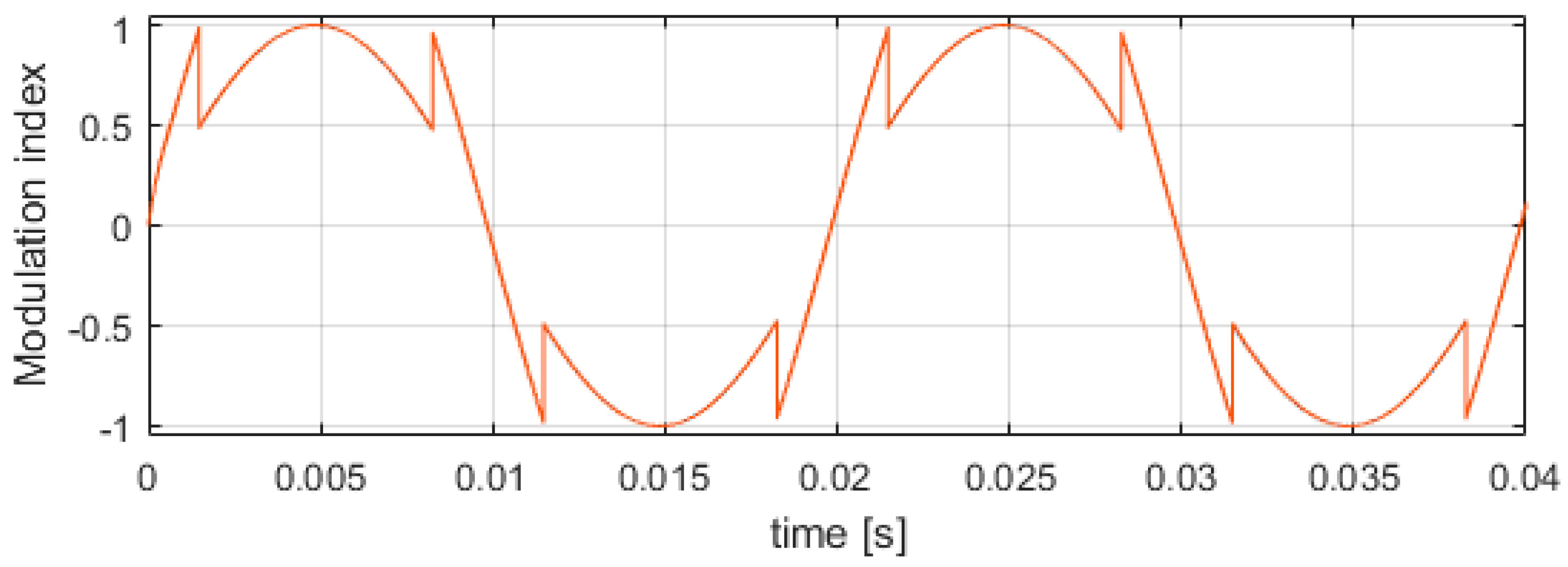
2.2.4. Simulation Results of Winding Reconfiguration

A first result of the control concept discussed above is shown in Figure 12.
Here, the circuit is generating a sine wave voltage across one winding pair. As shown, once the modulation index for the series connection reaches 1 or −1, the configuration is changed to independent and correspondingly, the modulation index used to generate the PWM signals is halved. Once the resulting index drops below 0.5, the series configuration is restored. In the implementation, a hysteresis between the value of the modulation index that triggers the series and independent operation can be applied to avoid ringing between series and independent operation command in the control system. The shape of the individual currents in a similar situation is shown in Figure 13. It can be seen that each current follows the set-point and the ripple of the sum current remains low in both the series and independent configurations.

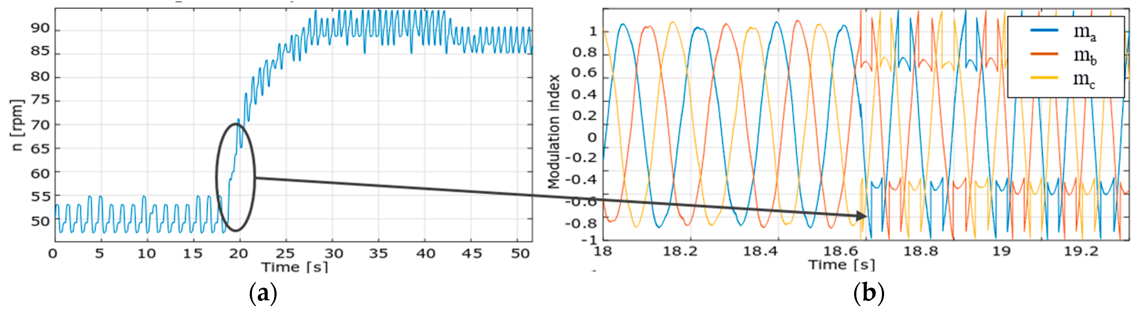
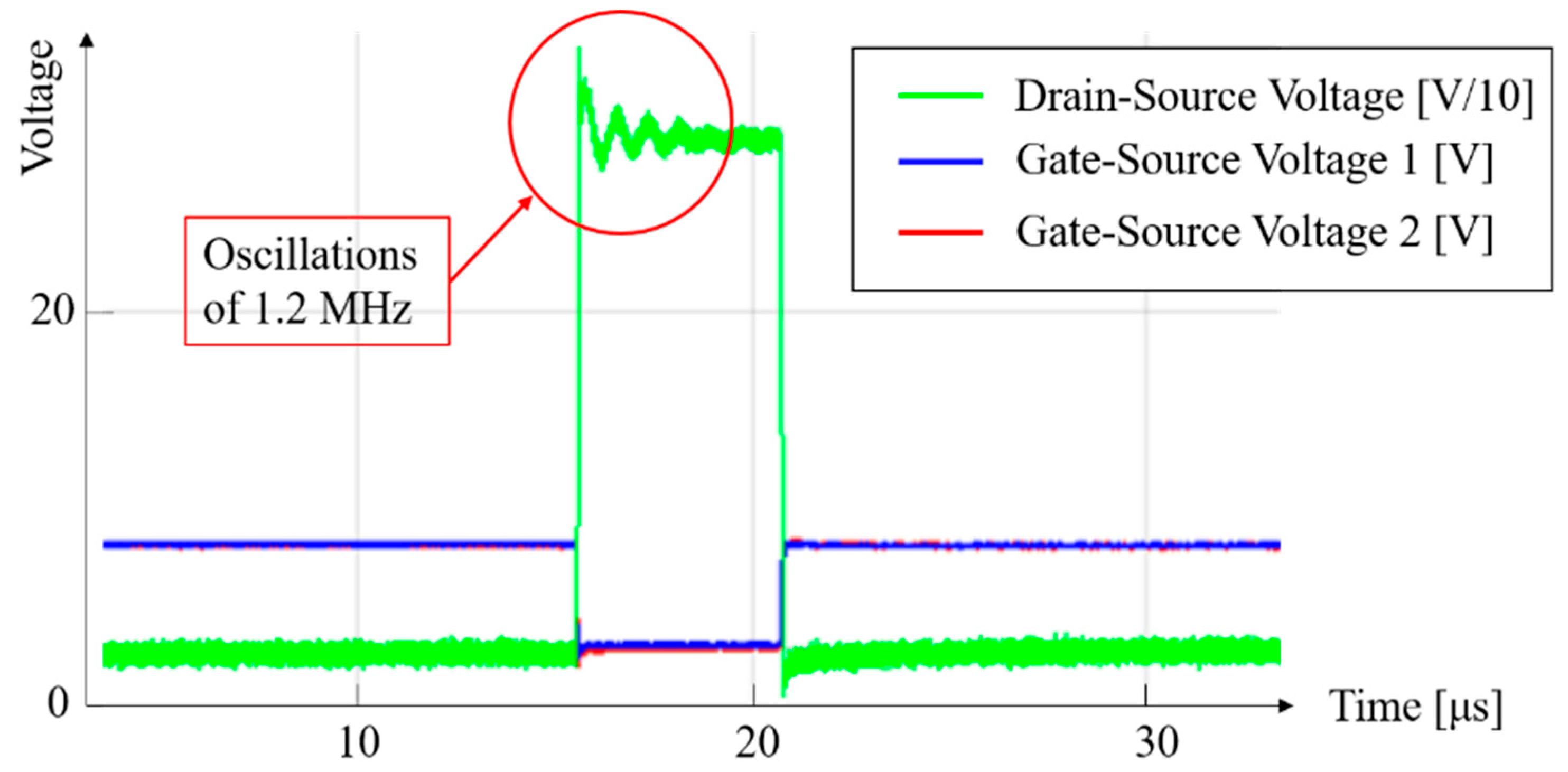
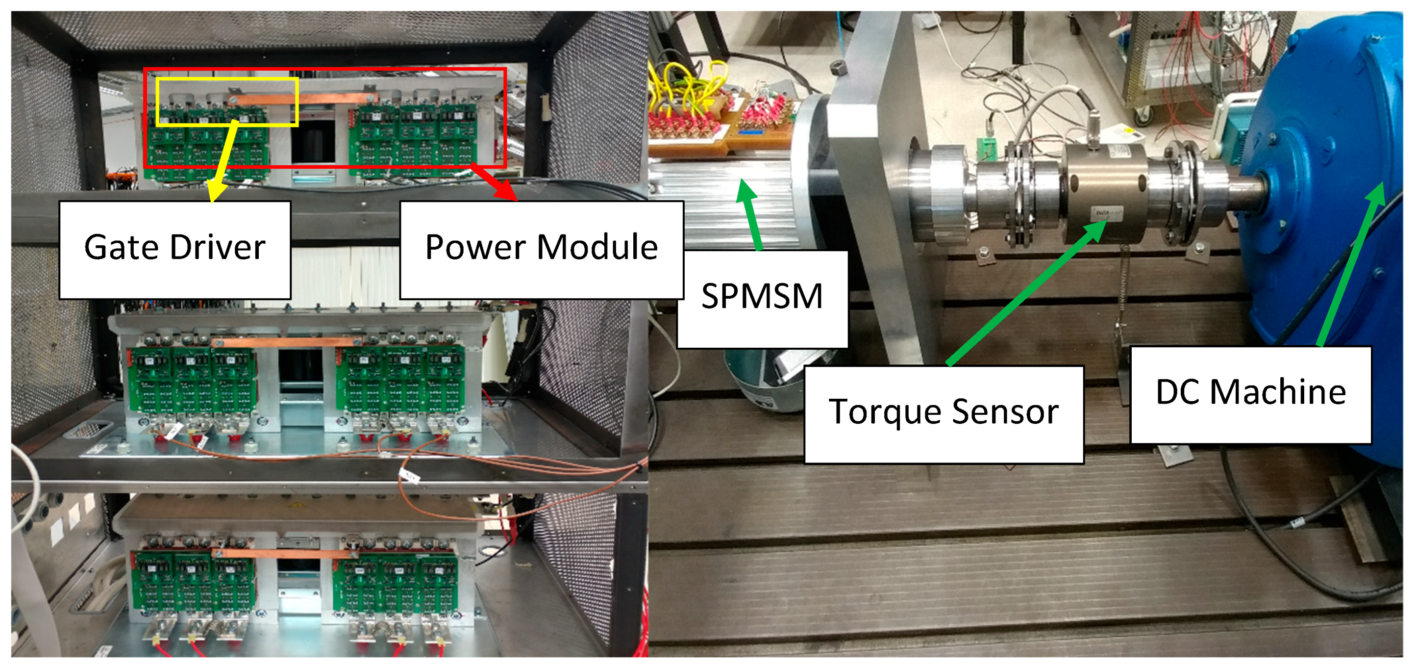
2.2.5. Experimental Results of Winding Reconfiguration.

To be able to already test the winding reconfiguration concept and the machine control in the absence of the final machine and power electronics hardware, an experimental setup, shown in Figure 14, was configured. In the setup, existing silicon IGBT power modules were re-used to supply an available six-phase open winding surface mounted permanent magnet synchronous machine (PMSM) loaded by a DC machine. The circuit configuration is similar to the one in Figure 10, but extended for a full double three-phase setup. However, due to limitations of the available hardware, only one series switch is present on each phase instead of two. The power rating of the available PMSM (4 kW), as in [16], is substantially lower than the final target, but this setup still allows for realistic testing of the developed algorithms, and as far as the electronic modules are concerned, full-power testing will be possible once the final SPMSM becomes available.
Figure 15a shows the SPMSM in the prototype setup being accelerated from 50 rpm to 90 rpm. As a result, the circuit that previously runs in all-time series operation enters the series-independent operation (see Figure 15b). The modulation index for each phase in the series-independent operation is further detailed in Figure 16. The initial experimental results verify the feasibility of the windings reconfiguration concept and thus open up the possibility of the final setup to be implemented with it. However, since in the planned final setup two series switches will be used, further investigation into the most optimal way to utilize the two series switches will be done in the future.

2.2.6. Industrialization Potential of GaN Devices
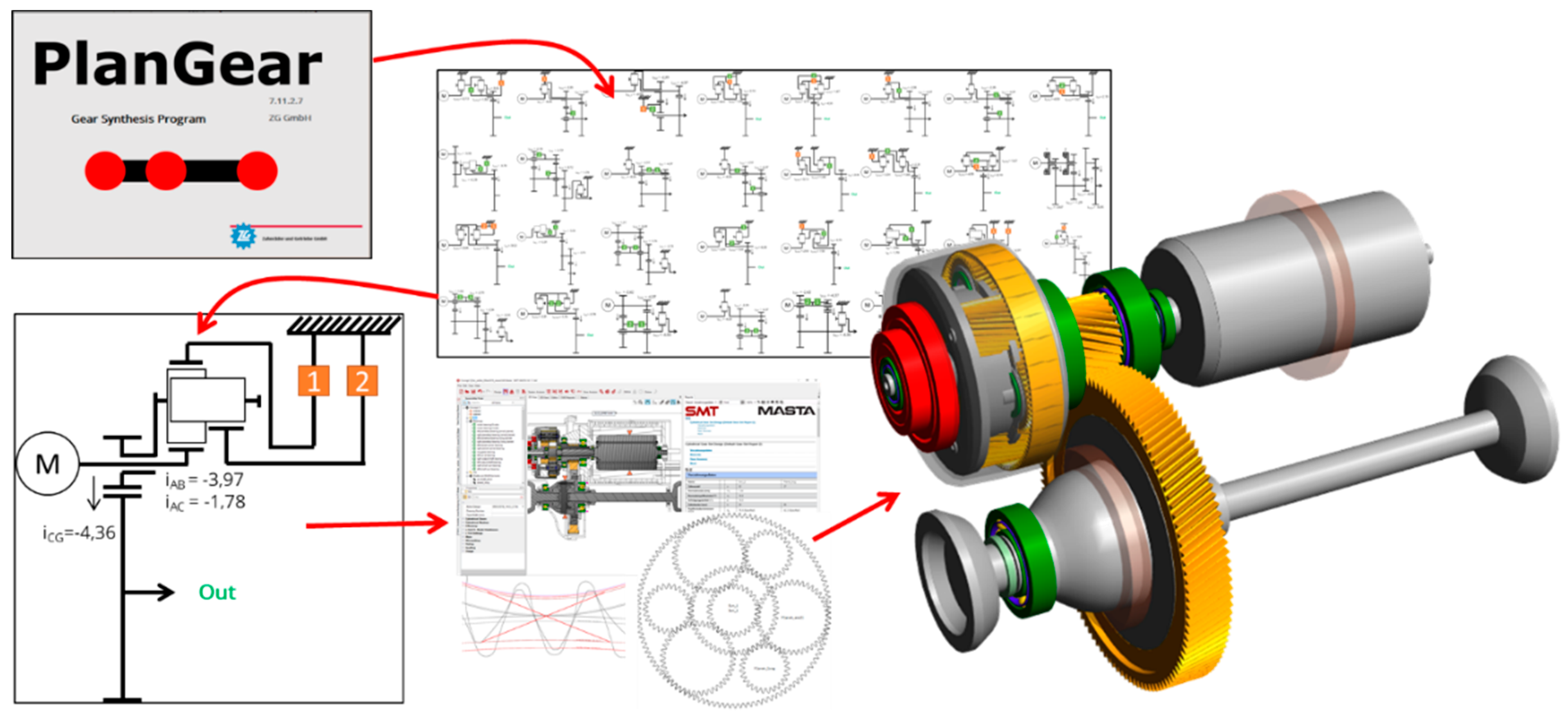
GaN is a young and emerging technology, which has a lot of advantages and great potential for automotive applications [12]. With increased switching frequency and low losses, it allows to build very efficient and compact power converters and inverters. Moreover, as it is a non-mature technology, technical improvements are to be expected, whether for the device performance itself (e.g., current capability and reliability) or the manufacturing process. As of today, the reliability of these devices cannot completely be assured, but the projects focus lies in the first application of this technology. Suppliers of GaN components foresee no problem in terms of reliability once the production ramps up and gets more mature. The prediction of CEA is that SiC devices will stay at the foreground for high voltage (>1 kV) applications. However, GaN technology will, in a few years, dethrone low voltage (<1 kV) technologies which have been installed for quite some time in power electronics, such as IGBTs and Cool-MOS [12].
Interestingly, it was noticed during the power board development that auxiliary components, such as passive components drivers and measurement probes, are not always adequate for use with GaN devices and progress has to be made also in those fields, without which the use and development of GaN-based inverters remains difficult.

2.3. Transmission

For the transmission, two options were considered in the project. The first option is a fixed-ratio single-speed transmission. The second option is a dual-ratio switchable transmission. Several aspects were considered to help make the decision:
  • Overall powertrain efficiency during type approval cycles: no clear winner between the two options
  • A dual ratio transmission with adapted ratios provides higher launch torque in first gear and higher top speed for the same motor speed in the second gear: this benefits the projects demonstrator that has limited motor torque due to the current limitations of the available GaN devices.
  • Market demand: some customers prefer a dual ratio transmission for EV powertrains for particular reasons (e.g., gradeability, large difference between empty vehicle mass and fully loaded vehicle mass).
As for the projects targets advantages of dual ratio transmission surpass disadvantages, it was decided to develop a dual-ratio switchable transmission. The ratios of the transmission are 21.65 for the first gear and 12.18 for the second gear, which leads to a ratio step of 1.78.
The development process is described as follows: With the help of the gear synthesis software PlanGear from ZG, different gear configurations could be elaborated on the level of stick diagrams. Out of 34 possible configurations which fulfil the drivetrain’s requirements, the four configurations with the highest efficiencies were depicted for further investigation. These configurations were then evaluated with respect to expected costs and overall size. Finally, the combination of a Ravigneaux planetary system and a pair of cylindrical gears was identified as the most promising solution. In a next step, gear and bearing dimensioning was elaborated with the use of the transmission calculation software MASTA by SMT. The shaft and bearing loads were based on highly demanding drive cycles. Figure 17 illustrates the design process of the gear and bearing configuration.
Several configurations were reviewed whilst taking the manufacturing methods for parts and the way of assembly of the powertrain into account. Subsequently, detailed gear and bearing lifetime calculations based on highly demanding drive cycles were performed. Load-capacity, efficiency, weight and costs of possible bearing arrangements were evaluated and compared. Where possible, ball bearings were applied to reduce transmission losses. Once the transmission layout was known, the oil routing was developed to ensure that all bearings and gears were lubricated sufficiently.
The specific challenge of finding a suitable high-speed motor bearing is eased by a smart motor shaft connection, which decouples the axial and radial forces of the transmission from the motor bearings. This makes it possible to choose very small, efficient and speed-resistant motor bearings. This can be seen in more detail in Figure 18: The motor shaft is connected with the sun gear of the planetary gear set through a hollow transmission shaft. By using a flexible spline connection, only torque is transmitted between motor and gear set and no axial or radial forces. The sun gear bearing is mounted in the planet carrier and thus, their relative speed is lower than the motor speed.

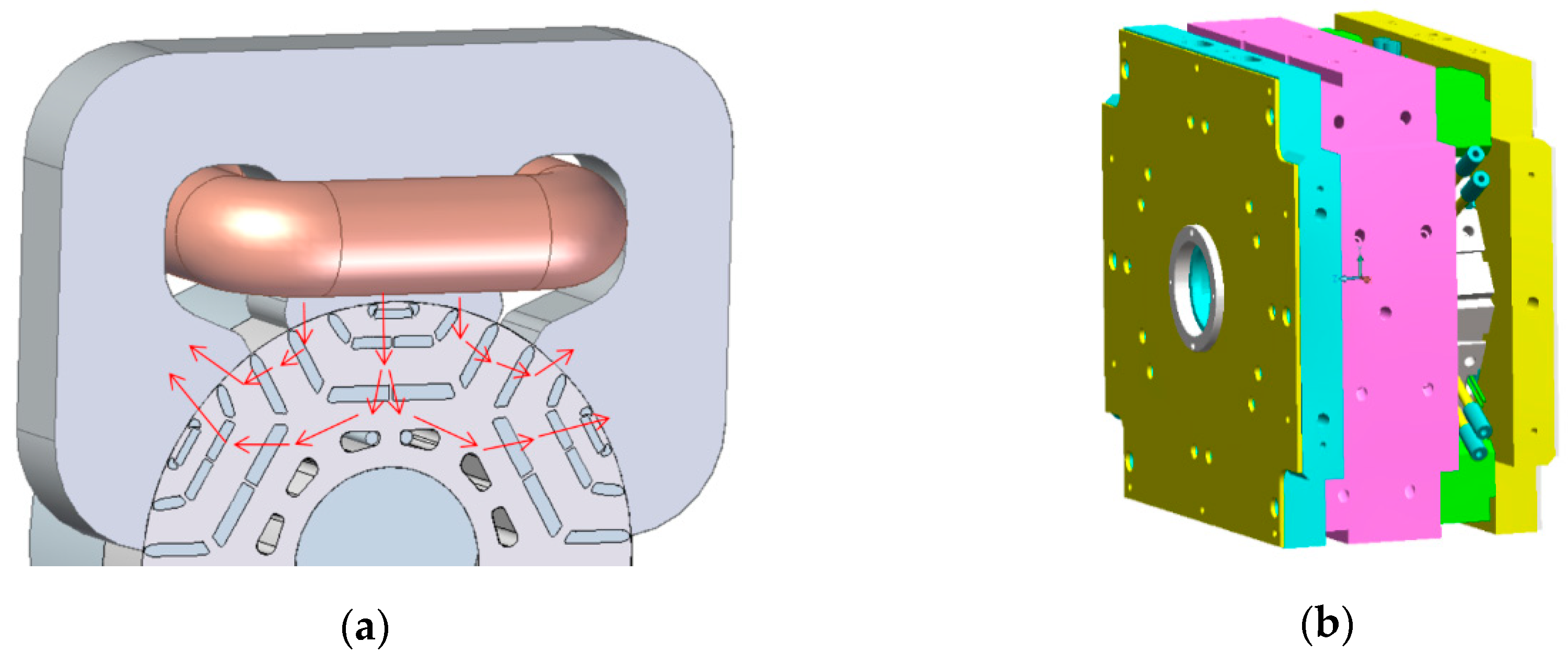
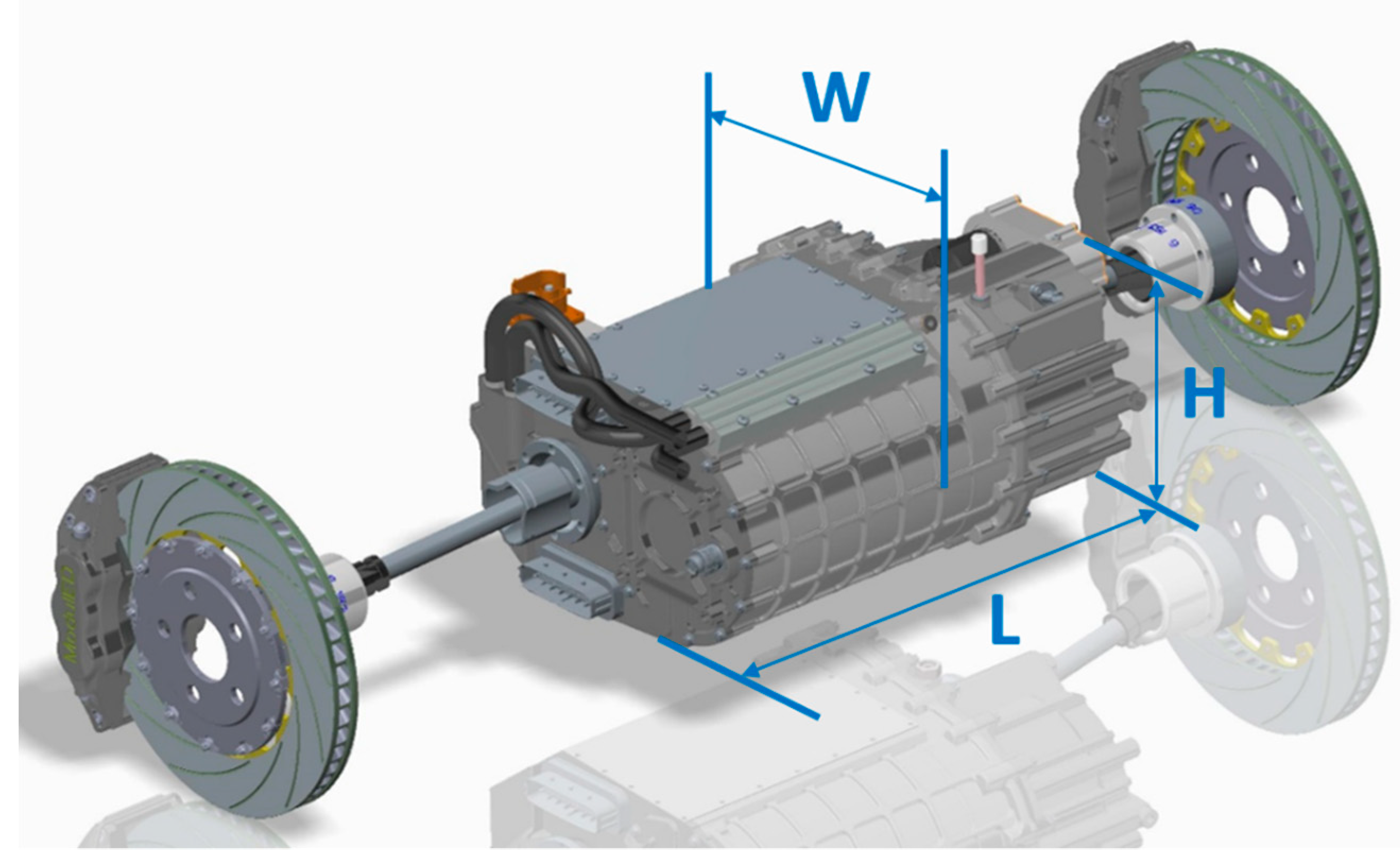
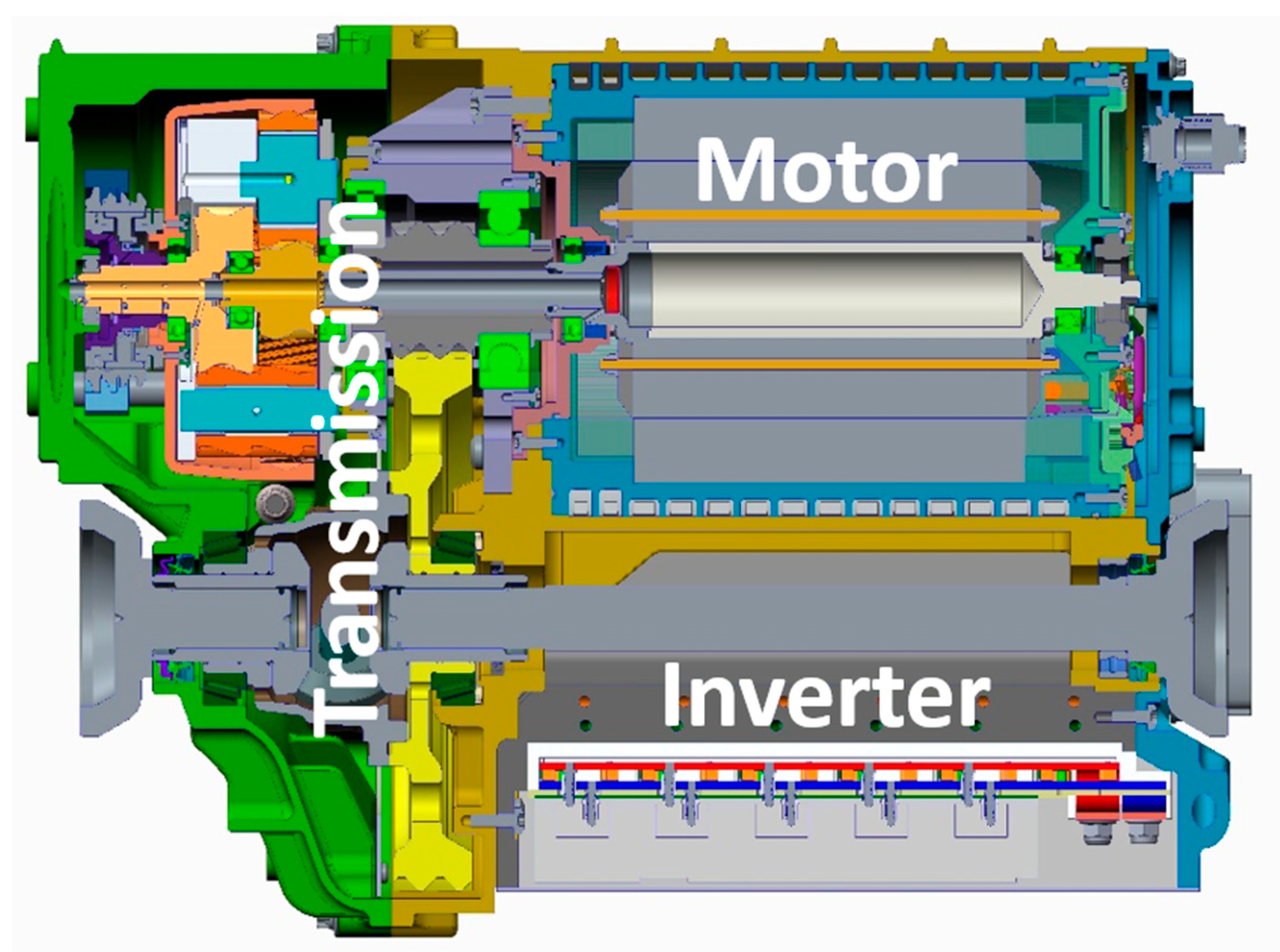
2.4. Module Assembly and Final Specifications

One of the ambitions of this project was to obtain a highly integrated, compact electric powertrain. The integration of motor, inverter and transmission into a single unit simplifies the powertrain assembly in the vehicle. Furthermore, the integration reduces the cost of interfacing by eliminating connectors, cables and covers. At the same time, a modular approach should allow exchanging (a part of) the motor, inverter or transmission for repair.
From different layouts, the consortium chose an arrangement in which the inverter boards are placed around the drive shaft, as can be seen in Figure 18.
This choice provides a compact unit with the best balance of length (L), width (W) and height (H) (Figure 19).
An important feature of the integrated housing is the cooling of both motor and inverter. Prior experience has shown that a too high back pressure in the cooling system requires a fairly high coolant pump power for the required flow. For this reason, the cooling subsystem puts the cooling of the motor and inverter in parallel. The motor cooling itself uses several parallel channels.
Having only one cooling circuit and all components integrated in one housing leads to a very compact overall design. Table 2 shows the resulting dimensions as well as peak power and torque.

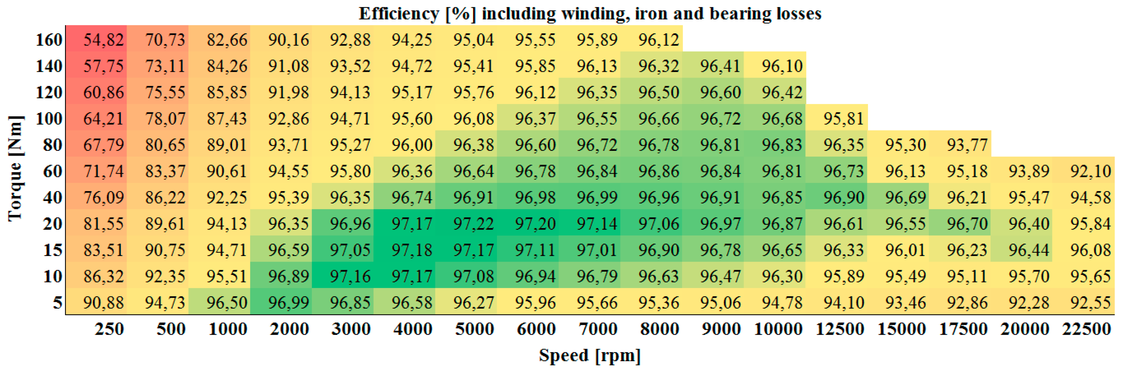
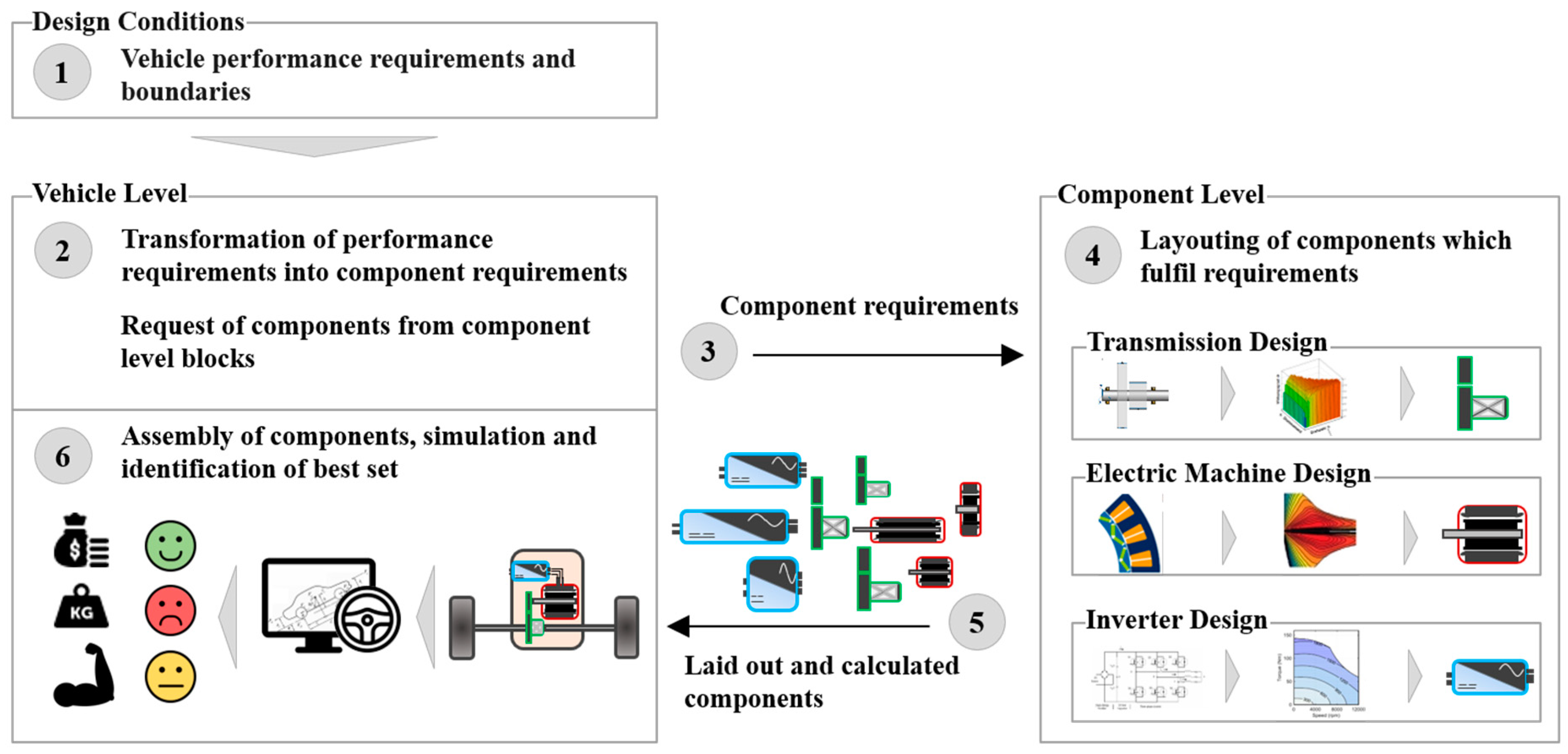
2.5. Holistic Design Approach

The best electric machine, the best inverter and the best transmission do not necessarily combine to the best drive module. This is because properties of fully electric drive modules result from multi-physical interaction of the powertrain components (electrical, mechanical and thermal). A design of the components with regard to the performance on vehicle level is necessary in order to find a global optimum for a specified vehicle and fixed driving requirements [17,18]. Furthermore, the control system design for the drive module is important to consider because it can increase the interaction between different subsystems but also be a remedy for unwanted interaction.
In parallel to the engineering of the drive module, a design process is being developed which aims to identify the best combination of components for the demonstrator vehicle [18]. “Best”, herein, means the ideal compromise between costs, efficiency, performance, weight, volume and complexity. The result is an iterative and computational intensive process, which involves detailed component modelling of transmission, electric machine and inverter, as well as vehicle longitudinal dynamics simulation in order to evaluate the components on system level (Figure 20).
In the first step, the requirements on vehicle level (e.g., acceleration from 0 to 60 km/h in 3.9 s) are broken down to component level (1 and 2). This results in a set of component requirements such as torque, power, gear ratio, etc. (3). The component level calculation blocks layout and design components to fulfil the requirements and return the results (4 and 5). The components are virtually assembled and the performance on system level is evaluated through numerical and analytical vehicle simulations. By weighting different design criteria, such as costs, performance, and weight, the best set of components for the specified target vehicle is found (6). As this study is ongoing and targeted to be completed in the beginning of 2020, no resulting drive module specification can be shown yet. However, the outcome of this design study is not only a suitable specification for drive modules for the Volvo C30e, but also to give insights into the component interaction between electric machine, inverter and transmission. The following findings have been gained to date during the development and usage of the presented design environment:
  • Electric Machine: High-speed EM generates power over high speeds and therefore, does need less winding current than low-speed EM. Ohmic losses in the windings are reduced while the iron losses slightly rise. However, the savings in winding losses surpass the additional iron losses and the machine is more efficient.
  • Inverter: Classical Si-based inverters are still a good choice for slow to medium switching frequencies. At high switching frequencies, GaN and SiC provide a suitable characteristic. The latter option leads to very compact inverters, as the size of the DC-link capacitor can be reduced with higher switching frequencies.
  • Transmission: With higher maximum EM speeds, higher reduction ratios are required and the transmission gets bigger and less efficient. For high reduction ratios, more complex topologies show advantages compared to simple spur gear designs.
  • Module Level: A module based on a high speed electric machine as presented above is more efficient and compact compared to conventional modules, even though the transmission itself is not. The drawbacks on the transmission side are overcompensated by the advantages on the machine and inverter side. However, due to high switching frequencies, conventional IGBTs produce high switching losses and thus, wide bandgap materials (GaN and SiC) should be used. Based on the current cost structures, the use of these materials results in a higher price on module level.

3. Conclusions

This project sets the stage for many innovations to prove its readiness for the automotive market. Many new technologies and the reason for their selection are presented here. Among these are Formed Litz wires, six-phase series-independent winding connection, injected magnets and a two-gear shiftable ravigneaux gear set.
The justification for the specific combination of these technologies comes from the striven high-speed concept, which makes the motor compact and efficient but introduces challenges for the transmission and inverter development. Furthermore, cost-effectiveness and environmental impact play an important role in technology selection.
The high rotational speed favors fast switching semiconductors, hence, a switch technology gallium nitride was chosen. It is specifically preferred over SiC due to its lower switching losses. In addition, high reduction ratios and two gears are required, and as the most compact and smart solution, a ravigneaux gear set was identified. The components were assembled in one housing with one cooling circuit and hence, a compact and flexible to use drive module was realized. Component tests are promising; the complete module assembly and the integration in a demonstrator vehicle will take place in the near future, in 2020.
As the overall conclusion, it can be said that the outcome of this project is a highly performant, compact and (potentially) cost effective drive module. It has the potential to increase attractiveness of electric drives over conventional vehicle and hence, to improve the adoption of them together with a reduction of worldwide CO2 and pollutant emissions.

Author Contributions

Conceptualization, J.H.; resources, L.E. and E.A.L.; writing—original draft preparation, J.H., H.H., J.A., D.O., C.L., O.T. and P.D.; writing—review and editing, J.H., M.R.L. and R.M.; supervision, D.K., L.E., E.A.L. and M.E.; project administration, C.L.

Funding

This research was funded by the European Comission under the Horizon 2020 programme, grant number 769953.

Acknowledgments

The authors want to express their gratitude for the opportunity of this research to the ModulED project (http://moduled-project.eu/), co-funded by the European Union under H2020 programme.

Conflicts of Interest

The authors declare no conflict of interest.

References

  1. Todts, W. CO2 Emissions from Cars: The Facts; European Federation for Transport and Environment AISBL: Brussels, Belgium, 2018. [Google Scholar]
  2. Auvinen, H.; Sampsa, R.; Juha, O.; Anu, T.; Toni, A. Process to Support Strategic Decision-Making: Transition to Electromobility. In Proceedings of the 2013 World Electric Vehicle Symposium and Exhibition, Barcelona, Spain, 17–20 November 2013; IEEE: Piscataway, NJ, USA, 2014. [Google Scholar]
  3. Damousis, Y.; Amditis, A.; Naberezhnykh, D. Electromobility: A Market Readiness Study—Preliminary Findings. In Proceedings of the IEEE IEVC’14, Florence, Italy, 16–19 December 2014. [Google Scholar]
  4. Lienkamp, M. Status Electromobility 2016: Or How Tesla Will not Win; Technische Universität München: Munich, Germany, 2016; p. 4. [Google Scholar]
  5. Boglietti, A.; El-Refaie, A.M.; Drubel, O.; Omekanda, A.M.; Bianchi, N.; Agamloh, E.B.; Popescu, M.; Gerlando, A.D.; Bartolo, J.B. Electrical Machine Topologies—Hottest Topics in the Electrical Machine Research Community; IEEE: Piscataway, NJ, USA, 2014; Volume 18, p. 24. [Google Scholar]
  6. Vagati, A.; Boazzo, B.; Guglielmi, P.; Pellegrino, G. Ferrite Assisted Synchronous Reluctance Machines: A General Approach. In Proceedings of the 2012 International Conference on Electrical Machines, Marseille, France, 2–5 September 2012; IEEE: Piscataway, NJ, USA, 2012. [Google Scholar]
  7. Tenconi, A.; Vaschetto, S.; Vigliani, A. Electrical Machines for High-Speed Applications: Design Considerations and Tradeoffs. IEEE Trans. Ind. Electron. 2014, 61, 3022–3029. [Google Scholar] [CrossRef]
  8. Benedikt Vogel (on behalf of: Swiss Federal Office of Energy SFOE, Bern, Switzerland). Electric Power Package with High Efficiency. Available online: https://www.researchgate.net/publication/ 332112701_Electric_Power_Package_with_high_Efficiency (accessed on 21 November 2019).
  9. Arnold Magnetic Technologies Co. N45UH Sintered Neodymium-Iron-Boron Magnets. Available online: https://www.arnoldmagnetics.com/wp-content/uploads/2017/11/N45UH-151021.pdf (accessed on 21 November 2019).
  10. Aichi Steel Corporation. MAGFINE® NdFeB Anisotropic Resin-Bonded Magnet—Technical Datasheet. Available online: https://www.aichi-steel.co.jp/ENGLISH/products/electromagnetic/bonded_magnet/ index.html (accessed on 21 November 2019).
  11. GaN Systems Inc. GS66516T Top-Side Cooled 650 V E-Mode GaN Transistor—Preliminary Datasheet. Available online: https://gansystems.com/gan-transistors/gs66516t/ (accessed on 13 March 2019).
  12. Kaminski, N.; Hilt, O. SiC and GaN Devices—Competition or Coexistence? In Proceedings of the 2012 7th International Conference on Integrated Power Electronics Systems (CIPS), Nuremberg, Germany, 6–8 March 2012; IEEE: Piscataway, NJ, USA, 2012. [Google Scholar]
  13. Gerrits, T.; Wijnands, C.G.E.; Paulides, J.J.H.; Duarte, J.L. Fault-Tolerant Operation of a Fully Electric Gearbox Equivalent. IEEE Trans. Ind. Appl. 2012, 48, 1855–1865. [Google Scholar] [CrossRef]
  14. Gerrits, T.; Wijnands, C.G.E.; Paulides, J.J.H.; Duarte, J.L. Electrical Gearbox Equivalent by Means of Dynamic Machine Operation. In Proceedings of the 14th European Conference on Power Electronics and Applications, Birmingham, UK, 30 August–1 September 2011. [Google Scholar]
  15. Gerrits, T.; Duarte, J.L.; Wijnands, C.G.E.; Lomonova, E.A.; Paulides, J.J.H.; Encica, L. Twelve-Phase Open-Winding SPMSM Development for Speed Dependent Reconfigurable Traction Drive. In Proceedings of the 2015 10th International Conference on Ecological Vehicles and Renewable Energies (EVER), Monte Carlo, Monaco, 31 March–2 April 2015; pp. 1–7. [Google Scholar]
  16. Daniels, B.; Gurung, J.; Huisman, H.; Lomonova, E.A. Feasibility Study of Multi-Phase Machine Winding Reconfiguration for Fully Electric Vehicles. In Proceedings of the 2019 9th International Conference on Ecological Vehicles and Renewable Energies (EVER), Monte-Carlo, Monaco, 8–10 May 2019; pp. 1–6. [Google Scholar]
  17. Albers, A.; Reichert, U.; Ott, S.; Radimersky, A. Software Supported Development Process of a Battery Electric Vehicle Powertrain Considering the Efficiency; VDI-Berichte: Düsseldorf, Germany, 2016; Volume 2276, pp. 321–337. [Google Scholar]
  18. Kieninger, D.; Hemsen, J.; Köller, S.; Uerlich, R. Automated Design and Optimization of Transmissions for Electric Vehicles. MTZ Worldwide 2019, 11, 94–98. [Google Scholar] [CrossRef]
Figure 1. Equivalent (von-Mises) stress at (a) rated speed of 22,500 rpm and (b) over-speed of 27,000 rpm for the sintered magnet rotor.
Wevj 10 00089 g001
Figure 2. (a) Classical Litz wire; (b) Formed Litz Wire (FLW) with increased fill factor in stator slot; (c) microscopic view of FLW [8].
Wevj 10 00089 g002
Figure 3. Simulated efficiency map of a Hybrid Synchronous Motor (HSM).
Wevj 10 00089 g003
Figure 4. (a) Principle of magnetization of permanent magnets; (b) Moulding tool for one rotor segment.
Wevj 10 00089 g004
Figure 5. Injected magnet samples.
Wevj 10 00089 g005
Figure 6. (a) Topology of the power board for one of six phases. (b) First prototype of one leg.
Wevj 10 00089 g006
Figure 7. Measured waveforms for two parallelized GaN devices.
Wevj 10 00089 g007
Figure 8. Bode diagram of the power circuit.
Wevj 10 00089 g008
Figure 9. (a) Top side of power PCB with GaN device; (b) bottom side; (c) electrical circuit of one leg.
Wevj 10 00089 g009
Figure 10. Switch matrix for one phase (winding pair).
Wevj 10 00089 g010
Figure 11. Control system for one phase (winding pair).
Wevj 10 00089 g011
Figure 12. Simulation result for one phase when generating a sine-wave voltage.
Wevj 10 00089 g012
Figure 13. Simulation result for one phase when generating a sine-wave voltage and current. Individual currents (a) and set point and actual sum current (b) Horizontal scale: (s), vertical: (A).
Wevj 10 00089 g013
Figure 14. Prototype setup for the windings reconfiguration concept verification. Three power converter modules, each for one phase, and the mechanical setup.
Wevj 10 00089 g014
Figure 15. (a) Acceleration of the permanent magnet synchronous machine (PMSM) from 50 rpm to 90 rpm; (b) the resulting modulation index during acceleration.
Wevj 10 00089 g015
Figure 16. Detailed measured modulation index for each phase in series-independent operation.
Wevj 10 00089 g016
Figure 17. From gear synthesis to simulation model.
Wevj 10 00089 g017
Figure 18. Cross section of chosen layout and arrangement of components in the housing.
Wevj 10 00089 g018
Figure 19. CAD drawing and main dimensions of developed powertrain module.
Wevj 10 00089 g019
Figure 20. Holistic design process of electric drive modules.
Wevj 10 00089 g020
Table 1. Motor specifications of developed motors and reference motor.
ParameterModulED Motor with Sintered MagnetsModulED Motor with Injected MagnetsReference Motor: BMW i3
Peak phase current (A rms)225225410
Winding typeFormed LitzFormed LitzClassical Litz
Number of phases663
Nominal speed (rpm)860086005000
Max speed (rpm)22,50022,50011,400
Peak torque (Nm)160156250
Peak power (kW)157158131
Battery voltage (VDC)320320360
Stator outer diameter (mm)176176242
Stator inner diameter (mm)118118180
Stack length (mm)179179130
Magnet Weight (kg)1.321.732.02
Peak power @360 VDC (kW)177178131
Magnet weight per kW (g)7.59.715.4
Magnet reduction compared to reference motor (%)52400
Table 2. Resulting module specifications.
ParameterValue
Width, length & height (W × L × H as in Figure 19)405 × 513 × 275 mm
Peak power at wheels157 kW
Peak torque at wheels3460 Nm
Required battery DC voltage320 V

