Article

Comparative Verification of Radiation Noise Reduction Effect Using Spread Spectrum for Inductive Power Transfer System

Department of Electrical, Electronics and Information Engineering, Nagaoka University of Technology, Niigata 940-2188, Japan
*
Author to whom correspondence should be addressed.
World Electr. Veh. J. 2019, 10(2), 40; https://doi.org/10.3390/wevj10020040
Submission received: 10 April 2019 / Revised: 23 May 2019 / Accepted: 6 June 2019 / Published: 10 June 2019

Abstract

:
This paper provides a comparative study on radiation noise reduction methods for inductive power transfer systems using spread spectrum. In the spread spectrum methods, the radiation noise is reduced by continuously changing an output frequency of the inverter according to pseudorandom numbers. The effects of the radiation noise reduction are evaluated with the inductive power transfer (IPT) system with series-parallel compensation and series-series compensation. The results show that the peak values of the radiation noise around the fundamental frequency are reduced by 7.8 and 8.1 dBμA in maximum with the series-series compensation method and the series-parallel compensation method, respectively in comparison with the constant frequency operation. From these results, the proposed methods are effective for both the series-series compensation and series-parallel compensation method. Moreover, the efficiency of the IPT system with spread spectrum method is evaluated. The maximum DC-to-DC efficiency with the spread spectrum is 94.1% and 92.0% with the series-series compensation and the series-parallel compensation, respectively.

1. Introduction

In recent years, inductive power transfer (IPT) systems for electric vehicles (EVs) have been actively studied and developed [1,2,3,4,5,6,7]. In particular, the practical realization of the IPT systems for EVs or plug-in hybrid EVs (PHEVs) is highly desired because the IPT systems will improve the usability of the EVs and the PHEVs. However, the IPT systems emit radiation noise. Therefore, in order to employ the IPT systems into practical applications, the radiation noise must be suppressed to satisfy existing standards, such as the well-known standard based on CISPR11, i.e., a standard regulated by the International special committee in radio interference. Otherwise, the IPT systems might affect other wireless communication systems or electronic equipment.
Figure 1 shows the maximum allowable radiation noise for the IPT systems of 7 kW or less for EVs in Japan. In Japan, the allowable radiation noise has been legislated. The regulations are currently under discussion for international standardization. An 85-kHz frequency band will be used as the transmission frequency in the international standard. This regulation is basically corresponding to CISPR 11 Group 2, Class B [8].
In previous studies, suppression methods using a magnetic material or metal shield have been proposed [9,10,11,12]. In order to suppress the radiation noise, transmission coils are surrounded by plates composed of magnetic material or metal plate. The radiation noise can be suppressed because these shields convert the magnetic flux from the radiation noise into eddy currents. However, the eddy current increases the power loss of the IPT systems. Moreover, the additional shields (magnetic or metal) lead to an increase in cost. So far, the authors have proposed two radiation noise reduction methods, in which the power is transmitted with changing switching frequency of the inverter continuously; it is also known as spread spectrum [13,14]. The proposed methods do not need additional components. Moreover, the effect on the efficiency by using the proposed method is small at the rated power [14]. In [14], the radiation noise reduction effect of these two proposed methods have been evaluated with the IPT system with a series-series (SS) compensation topology. The SS compensation topology is one of the dominant options for the standardization of International electrotechnical commission (IEC) because of their efficiency characteristic. However, the compensation topology should be discussed from a diversified standpoint including the radiation noise. Thus, this manuscript focuses on a comparison of the radiation noise between the SS compensation and series-parallel (SP) compensation. In [15], the radiation noise reduction technique is implemented for SP compensation. The performance of the radiation noise reduction between the SS compensation and the SP compensation is compared in [15]. However, the effect on transmission efficiency by employing the spread spectrum has not been evaluated.
In this paper, the proposed radiation noise reduction technique is employed for the SS compensation and the SP compensation. Then, the radiation noise reduction performance and the effect on the DC-to-DC efficiency are evaluated.

2. Radiation Noise Reduction Method

2.1. Generation Method of Pseudorandom Numbers

In the proposed method, the radiation noise is spread over the frequency domain from 80 kHz to 90 kHz by changing the switching frequency of the inverter in two different ways. The switching frequency is changed according to pseudorandom numbers, which are generated by using a maximum length sequence (M-sequence) shown as Figure 2. The M-sequence random number is generated as:
X z = X z p X z q
where Xz−p and Xz−q are the present values of Xz delayed by periods of p and q, respectively (p > q). In this paper, p = 7 and q = 1 are used. Note that the number of bits of the pseudorandom number is seven.

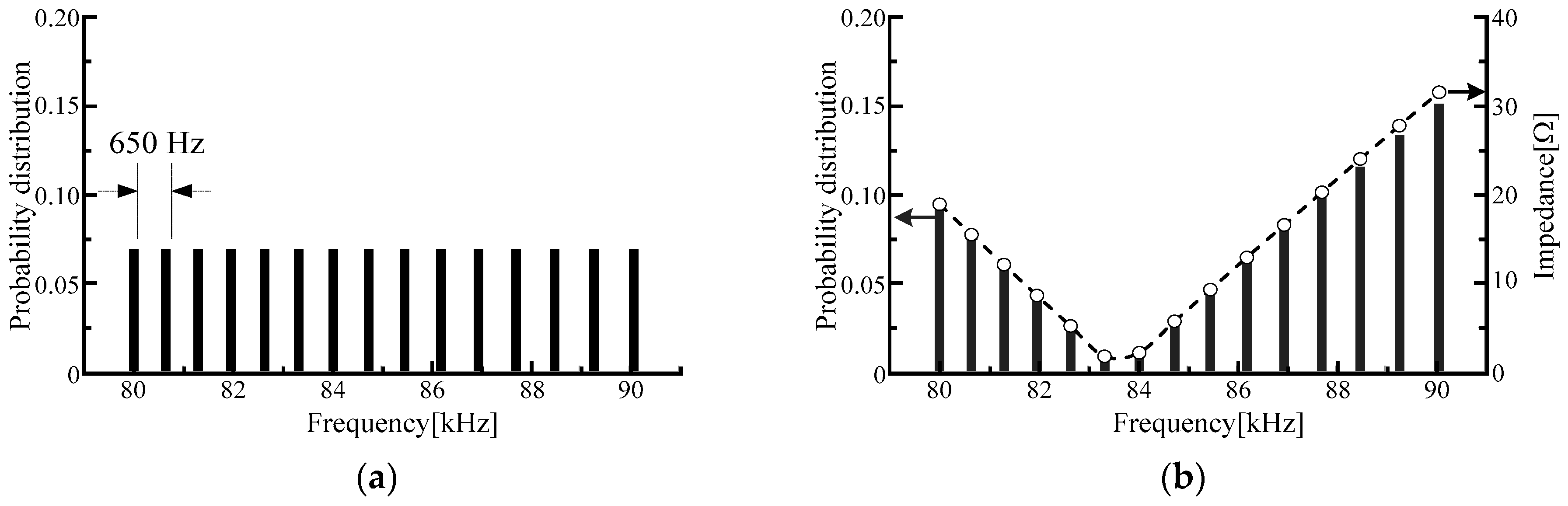
2.2. Probability Distributions for Reduction Method

Figure 3 shows the probability distribution of the switching frequency of the inverter in two proposed radiation noise reduction methods. Figure 3a shows the probability distribution of spread spectrum with a uniform distribution (SSUD) [2]. The probability distribution is a discrete uniform distribution from 80 kHz to 90 kHz. Therefore, the spectrum of the voltage applying to the transmission coil is uniformly spread. Figure 3b shows the probability distribution of spread spectrum with a biased distribution (SSBD) [3]. The input impedance depends on the switching frequency. Thus, the probability distribution is proportional to the impedance of the resonance circuit.

3. Design of Transmission Coil

Figure 4 shows the equivalent circuit for designing the IPT system. Figure 4a,b show the SS compensation topology and the SP compensation topology, respectively.

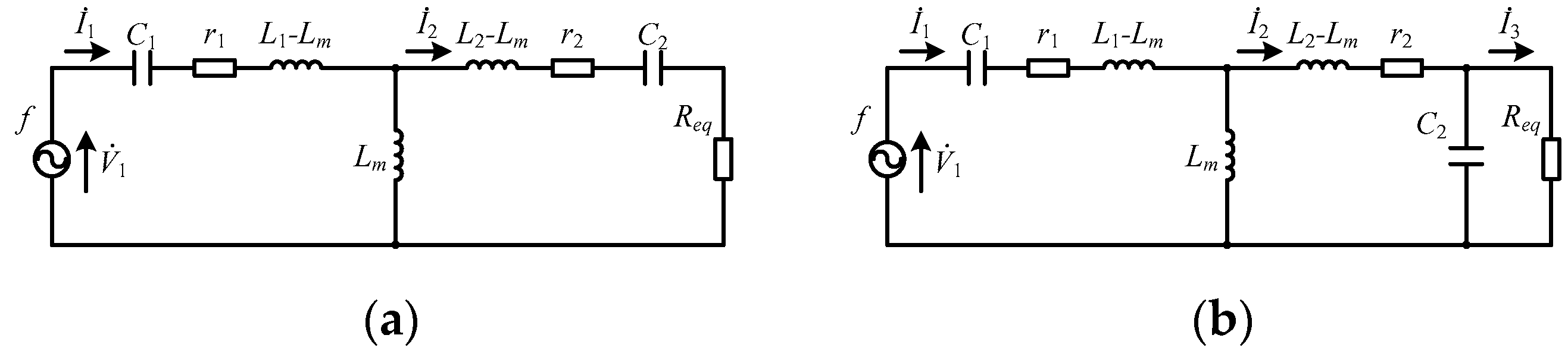
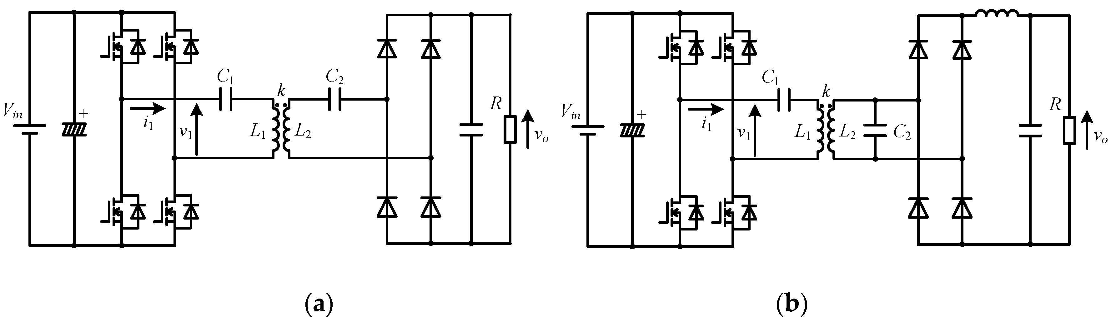
3.1. SS Compensation Method

From the circuit equations of the equivalent circuit, which are shown in Figure 4a, the primary current and the secondary current are calculated as:
I ˙ 1 = r 2 + R e q + j ( ω L 2 1 ω C 2 ) { r 1 + j ( ω L 1 1 ω C 1 ) } { r 2 + R e q + j ( ω L 2 1 ω C 2 ) } + ω 2 L m 2 V ˙ 1
I ˙ 2 = j ω L m { r 1 + j ( ω L 1 1 ω C 1 ) } { r 2 + R e q + j ( ω L 2 1 ω C 2 ) } + ω 2 L m 2 V ˙ 1
where V1 is the primary voltage, Req is the equivalent load resistance, r1 is the equivalent series resistance of the primary winding, r2 is the equivalent series resistance of the secondary winding, L1 is the primary inductance, L2 is the secondary inductance, C1 is the primary compensation capacitor, C2 is the compensation capacitor on the secondary side, Lm is the mutual inductance, and ω is the angular frequency of the power supply. Note that the voltage V1 is the fundamental component of the output voltage of the inverter.
The parameters of the transmission coil are designed with the equivalent circuit. The resistance Req indicates that equivalent load resistance considering the full-bridge rectifier. Then the equivalent load resistance is given by [16]:
R e q = 8 π 2 V D C , 2 2 P 2
where VDC,2 is the DC voltage on the secondary side and P2 is the output power.
The inductances of the primary and the secondary coils are designed according to the following equations:
L 1 = R e q ω k V D C , 1 2 V D C , 2 2
L 2 = R e q ω k
where VDC,1 is the DC voltage on the primary side and k is the coupling coefficient.
The compensation capacitors are selected in order to cancel out the reactive power at the input frequency. Thus, the value of the compensation capacitors is calculated as:
C 1 = 1 ω 2 L 1
C 2 = 1 ω 2 L 2

3.2. SP Compensation Method

The circuit equations of the equivalent circuit, which is shown Figure 4b are calculated as:
I ˙ 1 = { r 2 + j ( ω L 1 1 ω C 2 ) } ( R e q j 1 ω C 2 ) + 1 ω 2 C 2 2 Δ V ˙ 1
I ˙ 2 = j ω L m ( R e q j 1 ω C 2 ) Δ V ˙ 1
I ˙ 3 = 1 Δ L m C 2 V ˙ 1
Δ = | r 1 + j ω ( L 1 1 ω 2 C 1 ) j ω L m 0 j ω L m r 2 + j ω ( L 2 1 ω 2 C 2 ) j 1 ω C 2 0 j 1 ω C 2 R e q j 1 ω C 2 |
Note that the voltage V1 is the fundamental component of the output voltage of the inverter.
The parameters of the transmission coil are designed with the equivalent circuit. The resistance Req indicates the equivalent load resistance considering the full-bridge rectifier. Then the equivalent load resistance is given by [16]:
R e q = π 2 8 V D C , 2 2 P 2
The inductances of the primary and the secondary coils are designed according to the following equations:
L 1 = L 2 ( 8 π 2 k V D C , 1 V D C , 2 ) 2
L 2 = R e q ω k 1 + k 2
The compensation capacitors are selected in order to cancel out the reactive power at the input frequency. Thus, the values of the compensation capacitors are calculated as:
C 1 = 1 ω 2 L 1 ( 1 k 2 )
C 2 = 1 ω 2 L 2

4. Experimental Results

4.1. Experimental Setup

Figure 5 and Table 1 show the circuit configurations for the prototype and specifications, respectively. The self-inductance of the primary side and secondary side in Table 1 was measured from the prototype of the transmission coils. Silicon carbide MOSFETs were used as the switching devices in the inverter. Also, silicon carbide schottky barrier diodes were used in the rectifier.
Figure 6 shows the primary and secondary coils for the prototype. The common solenoid-type coils were used for both the compensation topologies. In order to obtain the common output power, the number of turns of the secondary coil was different between the SS compensation and SP compensation topology. In this paper, it is assumed that the transmission coils were well aligned. The effect on the spread spectrum performance by coil misalignment is reported in [17].

4.2. Operation Waveform

Figure 7 and Figure 8 show the operation waveform of the IPT system with SS and SP compensation, respectively. In all of the operation methods, the output power was fixed at 3.0 kW. Figure 7a shows the waveforms obtained using the conventional method with the output frequency fixed at 85.1 kHz. Figure 7b,c show the waveforms obtained using SSUD and SSBD, respectively. The output frequency of the voltage source inverter was randomly selected. When the spread spectrum methods were used, the amplitude of the primary current i1 varies. However, constant output voltages were obtained for all operation methods. In the waveforms with SP compensation, a similar characteristic was obtained as shown in Figure 8. Besides, when the operating frequency was higher than the resonant frequency due to the operation of spread spectrum, zero-voltage switching (ZVS) was achieved because the current flowed in the direction to discharge the parasitic capacitance of the MOSFETs, which would turn-on after the dead time, during the dead time. In contrast, ZVS was not achieved when the transmission frequency was lower than the resonant frequency.

4.3. Radiation Noise Measurement Conditions

Figure 9 shows the setup of the probe used for the measurement of the radiation noise. The radiation noise was measured at two points. Each distance from the edge of the transmission coils and to each measurement position was 500 mm.
Figure 10 shows the radiation noise with the SS compensation method. Figure 10a shows the result with a constant switching frequency operation, whereas Figure 10b,c show the results using the spread spectrum with SSUD and SSBD, respectively. As a result, by using the SSUD and SSBD, the radiation noise on the fundamental frequency was reduced by 4.8 dBμA and 7.8 dBμA in comparison with the conventional method. In addition, the effect of reduction was confirmed at low-order harmonics components, similarly.
Figure 11 shows the radiation noise with the SP compensation method. Figure 11a shows the result with a constant switching frequency operation, whereas Figure 11b,c show the results obtained using the SSUD and SSBD, respectively. As a result, by using the SSUD and SSBD, the fundamental frequency was reduced by 4.8 dBμA and 8.1 dBμA in comparison with the conventional method. In addition, the effect of reduction was confirmed at low-order harmonics components, similarly. As a result, the proposed radiation noise reduction methods were effective to reduce the fundamental and low-order harmonics components for both the SP and SS topology. However, the use of spread spectrum had a by-product. The continuous frequency change caused the increase of the sideband. The increase of the sideband could be adjusted to satisfy the standard by narrowing the frequency band for spread spectrum and decreasing number of frequency changes considered. These parameters should be adjusted with a 10m test range anechoic chamber. This adjustment should be done for each standard on the radiation noise. Therefore, this paper does not mention the adjustment of the effect of the sideband and only shows the comparison with and without the spread spectrum.

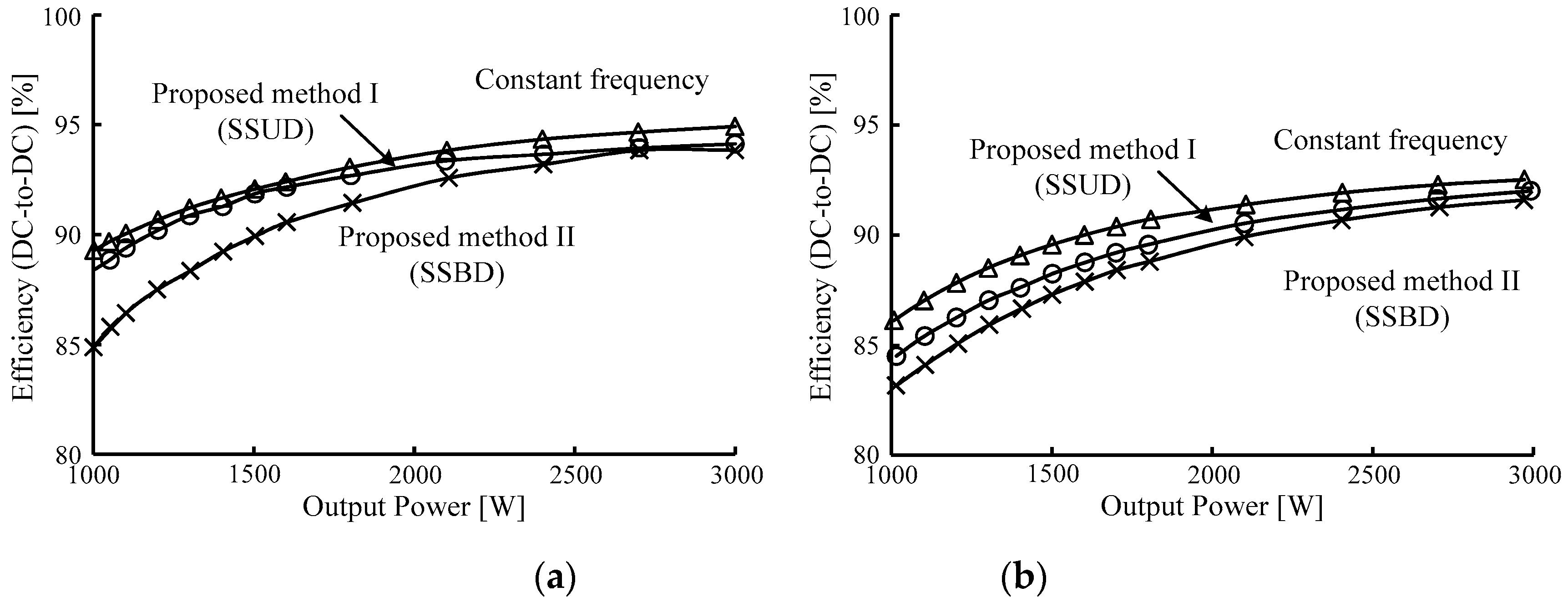
4.4. Efficiency Evaluation

The effect on the efficiency of the proposed spread spectrum was evaluated. Figure 12 shows the DC-to-DC efficiency characteristics of the IPT systems with or without the spread spectrum. The efficiency from the primary DC side to the secondary DC side was measured by the power analyzer (Yokogawa, WT1800). This means that the efficiency took into account the power loss of the inverter and the rectifier. The output power was changed by changing load resistance. In the SS compensation shown in Figure 12a, the maximum efficiency was 94.9%, 94.1%, and 93.8% without the spread spectrum, with SSUD, and with SSBD, respectively around an output power of 3 kW. Using the spread spectrum slightly reduced efficiency because the IPT system was operated at a slightly different frequency from the resonant frequency. Similarly, the maximum efficiency was 92.5%, 92.0%, and 91.6% without the spread spectrum, with SSUD, and with SSBD when the SP compensation was employed. Using the spread spectrum caused a difference between the operating frequency and the resonant frequency. The reactive current caused by the difference increased in copper loss of the transmission coils and the secondary coils. Moreover, it also increased the conduction loss of the inverter. Therefore the DC-to-DC efficiency dropped when the spread spectrum was implemented. Additionally, the SSBD selected the transmission frequency far from the resonant frequency with high probability. Thus, the efficiency drop of SSBD was higher than SSUD. The maximum efficiency was lower than the SS compensation because circulating current of the SP compensation on the secondary coil was larger than the SS compensation. It caused a larger copper loss on the secondary coil.
Note that the prototype was not optimized in terms of efficiency. Thus, the transmission efficiency will be improved by optimization.

5. Conclusions

The radiation noise reduction technique for IPT systems using the spread spectrum has been proposed by the authors. The radiation noise is reduced by continuously changing the output frequency of the inverter. In this paper, the radiation noise reduction effects of two proposed methods (the SSUD and the SSBD) were experimentally demonstrated with the IPT system of 3 kW prototype employing SS and SP compensation methods. In addition, the reduction effect is evaluated with the SS and SP compensation methods. As a result, the harmonics components around the fundamental frequency of the radiation noise with the SS compensation method were suppressed by 4.8 and 7.8 dBμA by applying the SSUD and the SSBD, respectively. On the other hand, in the SP compensation method, the harmonics components around the fundamental frequency of the radiation noise were suppressed by 4.8 and 8.1 dBμA by applying the SSUD and the SSBD, respectively. From the results, a radiation noise reduction effect is expected using the two proposed methods with IPT systems employing the SP compensation method as well as the SS compensation method.

Author Contributions

K.K. provided the concept of the proposed radiation noise reduction technique. J.I. supervised the work and contributed to the design of the prototype. K.I. performed the implementation and investigation. Then he mainly wrote the paper with input from all authors.

Funding

This research received no external funding.

Conflicts of Interest

The authors declare no conflict of interest.

References

  1. Hui, S.Y.R.; Zhong, W.; Lee, C.K. A Critical Review of Recent Progress in Mid-Range Wireless Power Transfer. IEEE Trans. Power Electron. 2014, 29, 4500–4511. [Google Scholar] [CrossRef]
  2. Shimode, D.; Mura, T.; Fujiwara, S. A Study of Structure of Inductive Power Transfer Coil for Railway Vehicles. IEE Jpn. J. Ind. Appl. 2015, 4, 550–558. [Google Scholar] [CrossRef] [Green Version]
  3. Hayashi, Y.; Chiku, Y. Contactless DC Connector Concept for High-Power—Density 380-V DC Distribution System. IEE Jpn. J. Ind. Appl. 2015, 4, 49–58. [Google Scholar] [CrossRef]
  4. Kusaka, K.; Orikawa, K.; Itoh, J.; Hasegawa, I.; Morita, K.; Kondo, T. Galvanic Isolation System with Wireless Power Transfer for Multiple Gate Driver Supplies of a Medium-voltage Inverter. IEEJ J. Ind. Appl. 2016, 5, 206–214. [Google Scholar] [CrossRef]
  5. Mizuno, T.; Ueda, T.; Yashi, S.; Ohtomo, R.; Goto, Y. Dependence of Efficiency on Wire Type and Number of strands of Litz Wire for Wireless Power Transfer of Magnetic Resonant Coupling. IEEJ J. Ind. Appl. 2014, 3, 35–40. [Google Scholar] [CrossRef]
  6. Trung, N.K.; Ogata, T.; Tanaka, S.; Akatsu, K. Analysis and PCB Design of Class D Inverter for Wireless Power Transfer Systems Operating a 13.5 MHz. IEEJ J. Ind. Appl. 2015, 4, 703–713. [Google Scholar]
  7. Boys, J.T.; Covic, G.A.; Xu, Y. DC Analysis Technique for Inductive Power Transfer Pick-Ups. IEEE Trans. Power Electron. 2003, 1, 51–53. [Google Scholar] [CrossRef]
  8. Ministry of Internal Affairs and Communications. Inquiry of Technical Requirements for Wireless Power Transfer System for EVs in Technical Requirements for Wireless Power Transfer System in Standards of International Special Committee on Radio Interference (CISPR); Ministry of Internal Affairs and Communications: Tokyo, Japan, 2015.
  9. Jo, M.; Sato, Y.; Kaneko, Y.; Abe, S. Methods for Reducing Leakage Electric Field of a Wireless Power Transfer System for Electric Vehicles. In Proceedings of the 2014 IEEE Energy Conversion Congress and Exposition (ECCE), Pittsburgh, PA, USA, 14–18 September 2014; pp. 1762–1769. [Google Scholar]
  10. Kim, H.; Cho, J.; Ahn, S.; Kim, J.; Kim, J. Suppression of Leakage Magnetic Field from a Wireless Power Transfer System using Ferrimagnetic Material and Metallic Shielding. In Proceedings of the 2012 IEEE International Symposium on Electromagnetic Compatibility, Pittsburgh, PA, USA, 6–10 August 2012; pp. 640–645. [Google Scholar]
  11. Campi, T.; Cruciani, S.; Feliziani, M. Magnetic Shielding of Wireless Power Transfer Systems. In Proceedings of the 2014 International Symposium on Electromagnetic Compatibility, Tokyo, Japan, 12–16 May 2014; pp. 422–425. [Google Scholar]
  12. Maikawa, K.; Imai, K.; Minagawa, Y.; Arimitsu, M.; Iwao, H. Magnetic Field Reduction Technology of Wireless Charging System. In JSAE Annual Congress Autumn 2013; JSAE: Tokyo, Japan, 2013. [Google Scholar]
  13. Kusaka, K.; Inoue, K.; Itoh, J. Reduction in Radiation Noise Level for Inductive Power Transfer System with Spread Spectrum. In Proceedings of the International Electric Vehicle Technology & Automotive Power Electronics Japan Conference, Yokohama, Japan, 25–30 May 2016. No. 20169063. [Google Scholar]
  14. Inoue, K.; Kusaka, K.; Itoh, J. Reduction in Radiation Noise Level for Inductive Power Transfer Systems using Spread Spectrum Techniques. IEEE Trans. Power Electron. 2018, 33, 3076–3085. [Google Scholar] [CrossRef]
  15. Kusaka, K.; Inoue, K.; Itoh, J. Comparative Verification of Radiation Noise Reduction Effect using Spread Spectrum for Inductive Power Transfer System. In Proceedings of the 31st International Electric Vehicles Symposium & Exhibition & International Electric Vehicle Technology Conference 2018 (EVS 31 & EVTeC), Kobe, Japan, 30 September–3 October 2018. No. 20189223. [Google Scholar]
  16. Bosshard, R.; Kolar, J.W.; Muhlethaler, J.; Stevanovic, I.; Wunsch, B.; Canales, F. Modeling and η-α-Pareto Optimization of Inductive Power Transfer Coils for Electric Vehicles. IEEE J. Power Electron. 2014, 3, 50–64. [Google Scholar]
  17. Kusaka, K.; Inoue, K.; Itoh, J. Radiation noise reduction using spread spectrum for inductive power transfer systems considering misalignment of coils. In Proceedings of the 2017 IEEE Energy Conversion Congress and Exposition (ECCE), Cincinnati, OH, USA, 1–5 October 2017; pp. 5507–5514. [Google Scholar]
Figure 1. Maximum allowable radiation noise for inductive power transfer (IPT) system of 7 kW or less for use in electric vehicles (EVs) in Japan (under discussion).
Wevj 10 00040 g001
Figure 2. Generation method of pseudorandom numbers based on maximal length sequence.
Wevj 10 00040 g002
Figure 3. Probability distributions for proposed methods. Changing range of switching frequency of inverter is from 80 kHz to 90 kHz: (a) is the proposed method I (SSUD), and (b) is the proposed method II (SSBD).
Wevj 10 00040 g003
Figure 4. Equivalent circuits for designing the IPT systems: (a) is the SS compensation method, and (b) is the SP compensation method.
Wevj 10 00040 g004
Figure 5. Circuit configuration of prototype: (a) is the series-series (SS) compensation method, and (b) is the series-parallel (SP) compensation method.
Wevj 10 00040 g005
Figure 6. Transmission coils with rated power of 3 kW. Lower side is transmitter coil, upper side is receiver coil. White winding on the secondary side is used as SS compensation method. Red winding on secondary side is used as SP compensation method.
Wevj 10 00040 g006
Figure 7. Operation waveforms with SS compensation: (a) is the constant frequency operation, (b) is the spread spectrum with a uniform distribution (SSUD), and (c) is the spread spectrum with a biased distribution (SSBD).
Wevj 10 00040 g007
Figure 8. Operation waveforms with SP compensation: (a) is the constant frequency operation, (b) is the SSUD, and (c) is the SSBD.
Wevj 10 00040 g008
Figure 9. Measurement environment of radiation noise: (a) is the measurement point A, (b) is the measurement point B. The distance from the edge of the transmission coils to each measurement position is 500 mm.
Wevj 10 00040 g009
Figure 10. Radiation noise at measurement point A in y-z plane with SS compensation: (a) is the conventional method with constant frequency, (b) is the proposed method I: SSUD, and (c) is the proposed method II: SSBD.
Wevj 10 00040 g010
Figure 11. Radiation noise at measurement point A in y-z plane with SP compensation: (a) is the conventional method with constant frequency, (b) is the proposed method I: SSUD, and (c) is the proposed method II: SSBD.
Wevj 10 00040 g011
Figure 12. Efficiency characteristic with (a) SS compensation, and (b) SP compensation.
Wevj 10 00040 g012
Table 1. Specifications of prototype.
SymbolValue
Input DC voltageVin420 V
Rated powerP3.0 kW
Coupling coefficientk0.20
Primary inductanceL1392 H
Secondary inductanceL2401 μH (SS)
24.2 μH (SP)
Primary capacitanceC18.96 nF
Secondary capacitanceC28.78 nF (SS)
145 nF (SP)
Transmission distancel150 mm

