Abstract
This research investigates the most modern approaches to water treatment and recovery in power plants because of the scarcity of water sources and the significance of those sources in enhancing the performance of power-generating cycles. Gas turbines, which use mixes of air and water as the working fluid, provide superior efficiency, high specific power outputs, and reduced investment costs compared to combined cycles. Several different cycles for humidified gas turbines, including cycles of direct water injection, cycles of steam injection, and evaporative cycles that include humidity control towers, have been proposed. Despite this, only a few of these cycles have been put into practice, and even fewer are available for purchase on the market. This work aims to analyze the research and development literature on humidification-based gas turbines and highlight the cycles that have the most significant promise for the long run. In addition, work on development that still has to be carried out in order to deploy humidification-based gas turbine cycles is advised. This article may also be used as an overview of the research and development work that has taken place on humidification-based gas turbines over the course of the last thirty years.
1. Introduction
The International Energy Agency (IEA) projects that the yearly growth rate of global energy consumption will be 1.7% between 2000 and 2030. This rise is comparable to two-thirds of the current primary energy demand, which was 9179 Mtoe in the year 2000, and fossil fuels will continue to account for the bulk of the market for energy in the year 2030. In addition, the International Energy Agency (IEA) projects that the annual growth rate of electricity demand would be 2.4%. Natural gas-fired combined cycles will account for the vast majority of new power generation capacity [1]. It is essential to develop improved power generating systems that have high levels of electrical efficiency with high levels of generated power (kilojoules of power per kilogram of air), low levels of emissions of pollutants, and minimal expenses of investment, operation, and upkeep in order to make sustainable use of the fuels that are currently available. Gas turbines are able to fulfill the requirements because they have high efficiency, cheap capital costs (USD/kWe), excellent power/weight ratio, and reduced air pollution. The energy markets of many countries have been deregulated, which has increased the competition for distributed generation and independent power providers; because of these modifications, power plants that have outputs ranging from low to medium need to be very efficient and adaptive. Consequently, it was expected that by the late 1980s, power stations would account for more than fifty percent of new orders for fossil-fueled power plants [2]. This was due to the fact that natural gas was readily available, relatively inexpensive, and free of contaminants; moreover, the need for gas turbines is still increasing [3]. Research and development efforts have focused on improving component designs, cooling, and combustors, as well as innovative materials, in order to increase the efficiency and specific power production of gas turbines. These improvements include increasing the firing temperature and the pressure ratio (4), the conversion of aviation gas turbines to power-generating applications and the transfer of technology from gas turbines used in airplanes to gas turbines used in stationary power plants (5), and cycle configuration (e.g., combined-cycle integration, inter-cooling, recuperation, reheat, chemical recuperation).
To improve the performance of gas turbines, it is common practice to combine a number of the available alternatives. Additionally, by humidifying the working fluid of a gas turbine, it is possible to boost the machine’s output and efficiency. There have been many different injection cycles that use water or steam, but only a few have been put into practical use. The potential for high electrical efficiency, specific power output, and reduced specific investment cost, decreased formation of nitrogen oxides (NOx) in the combustor, reduced power output degradation caused by high ambient temperatures or low ambient pressures (i.e., at high altitudes), and improved part-load performance compared with combined cycles are the driving forces behind gas turbine humidification.
The concept behind humidifying gas turbines is that increasing the amount of water/steam injected into the turbine increases the amount of mass it moves. This results in a rise in the specific power output because the effort exerted by the compressor remains the same (i.e., if water is introduced post the compressor), and it takes far less effort to raise the pressure of a liquid than it does of a gas. The efficiency of the cycle may be improved by recovering the energy contained in the gas turbine’s exhaust and either preheating the injection water, making injection steam, or the recuperator’s preheating of the combustion oxidizer. Additionally, the introduction of water prior to the combustor of a recuperated gas turbine lowers the compressed air’s temperature at the input of the recuperator. This results in an increase in the rate at which energy is recovered from the exhaust gas.
Additionally, in a dry-gas-based turbine, the supply rate of the combustion air is lower than that of the exhaust gas. This is due to the fact that a lot of air is utilized to cool the combustor and expander, and the air and exhaust gas have different specific heat capacities. These two elements lower the recuperator heat recovery system’s effectiveness. Humidification, on the other hand, increases both the amount of heat produced and the combustion air mass flow rate, ultimately improving the recuperator’s overall performance. The work required to compress the fuel is reduced whenever steam or water is introduced into the combustor, replacing some of the combustor’s cooling air. Because the combustion gases provide the heat necessary to evaporate water, the combustor is cooled more effectively by water than steam at the same injection mass flow rate. Adding humidity to the gas turbine’s working fluid has the advantage of lowering the amount of NOx produced during the combustion techniques.
This article reviews humidified gas turbines that have been proposed and implemented in the past. The goals of this review are to identify systems that promise reduced cost, and high-specific power production, to highlight the developments that are being achieved in this area, and to address the technical issues that need to be resolved.
This article references a significant number of previous studies on various cycles for humidified gas turbines. The selected papers were deemed the most fascinating, such as those that detailed a unique cycle arrangement or application. This research section first discusses the underlying notion that underpins humidified gas turbines. This article examines research on water-recovery methods, the thermo-physical characteristics of air/water mixtures, ignition with moist air separately, standardizing humidification-based power plant performance data, and the promise of carbon dioxide recovery at a lower cost than for dry cycles.
2. Concepts of Humidification-Based Gas Turbines
The humidification-based power plants that have been discussed in the past are organized into the following three groups according to this article:
- Gas turbines with water injection that results in complete evaporation of the water. Systems that have water injected at the compressor intake for the purpose of increasing power output on hot days; systems that have water injected in the compressor for the purpose of intercooling; and systems that have water injected after the compressor in conjunction with recuperation fall under this category. Injection of water or steam into the combustor is a mature strategy for minimizing the formation of nitrogen oxides (NOx), although deployment of the two types of systems that were just discussed has been minimal.
- Gas turbines that get steam injections. This category encompasses a wide variety of commercially available systems.
- The gas turbine that runs while water is injected into a humidification tower and recirculated through the system. The terms evaporation-based power plants (EvGT) and humid-air turbines (HAT) are often used to refer to these cycles. According to the study’s authors, the sole evaporative cycle currently operates at a pilot plant in Sweden [4].
The systems that fall into the first group are shown in a diagrammatic form in Figure 1. The fact that the power output of a basic cycle power plant reduces by 0.4–0.8% when the average temperature of the environment rises by one degree Celsius illustrates how strongly the ambient temperature influences the power output [4]. This indicates that power plants are highly dependent on ambient temperature. Due to the fact that the volume flow rate of the compressor does not change even when the shaft speed is held constant, the air density and the mass flow rate of the compressor are both reduced when the ambient temperature is high. Input air-cooling lowers the temperature at the compressor’s input, increasing the air’s density. In systems where water is utilized, water reduces the air’s temperature and raises the working fluid’s mass flow rate. Figure 1 also depicts a wet-compression technique, in which water is introduced between the compressor’s stages, as well as an evaporation-based or spray-based inter-cooling technique, in which water is introduced between the LP and HP compressors. Both systems are designed to reduce the heat generated by the compression process. Both of these approaches reduce the effort needed for compression by using air intercooling. Evaporatively aftercooled, and recuperated gas turbines have been the subject of study by a large number of scientists, as can be shown in a schematic representation in Figure 1. The authors of this work, however, were unable to find any articles that discussed the operation of such systems. When the cycle uses surface intercooling, the warm water from the intercooler is often pumped into the cycle. In most cases, it is presumed that water is pumped into a chamber in order to delay the flow of air and provide adequate time for the water to evaporate. In the absence of a saturation chamber, Rogers and Liese [5] investigated the effects of direct water injection by the use of a pressure-swirl nozzle into a high-pressure, fast-moving air stream. When hot water is sprayed, it atomizes, resulting in smaller droplet sizes, increased evaporation rates, and a closer approach to saturation than when cold water is sprayed. Although direct water injection in a gas turbine is not capable of completely saturating the air, the pressure loss induced by the water injection is low, and the device is affordable and condensed.
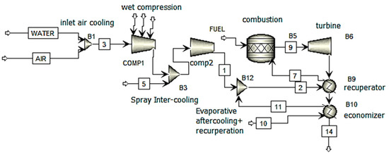
Figure 1.
A system with wet compression, spray intercooling, evaporative aftercooling, and recovery of the cooled intake air (the water is delivered as a fog of water droplets or as a media cooler).
In steam-injected gas turbines, the steam is created prior to, throughout, or following the combustor, as well as in between the stages of the turbine, and the exhaust gas is introduced into the gas turbine. This may be shown schematically in Figure 2. It is necessary for the steam to be super-heated and at a higher pressure than the compressor discharge pressure in order to prevent water droplets from forming in the combustor, causing rusting. The layout of a typical evaporative gas turbine cycle is shown in the schematic drawing shown in Figure 2. In this cycle, energy is reclaimed by the use of water in the economizer, intercooler (if present), and after-cooler, in addition to the usage of humid air in the recuperator. The humidification tower, an essential component of the evaporative cycle, takes the role of the cycle’s boiler in steam-injection-based cycles and the evaporation-based chamber in water-injection-based cycles. This change allows the evaporative cycle to function more efficiently. A part of the water evaporates as a direct consequence of the simultaneous mass and heat transfer process. As a result, in the majority of instances, hot and humid air is evacuated from the top of the tower. Instead of boiling at a temperature that would be related to the total pressure of the system, the water will evaporate at a temperature that is determined by the partial pressure of water in the air. As a result, water may evaporate at lower temperatures than is typically possible in a boiler, as evaporation happens at lower levels of temperature than what is feasible in a normal boiler.
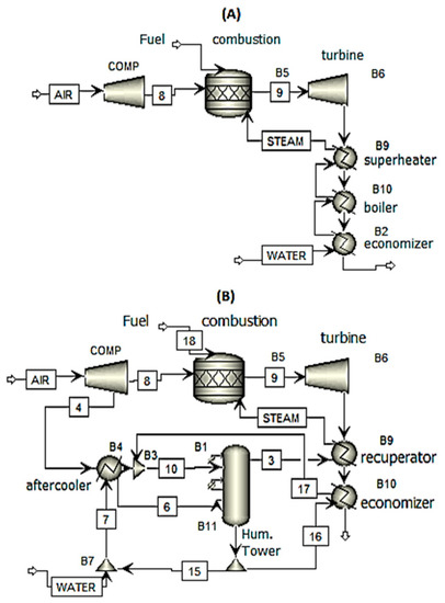
Figure 2.
Schematic steam-injection-based gas turbine (A) and one possible evaporation-based gas turbine cycle (B).
In contrast, the pinch point inhibits heat recovery in the boiler during the steam-injected cycle, and low-temperature energy cannot be used to vaporize water. This is because the pinch point is located at the point where the steam and water meet. As the air travels higher up the tower, it comes into contact with water that has a higher temperature. This is part of the evaporative cycle.
As one moves higher up the tower, the relative humidity of the air increases, which in turn causes the temperature of evaporation to climb. The boiler in a steam-injected cycle undergoes an isothermal boiling process, which causes a mismatch between the temperature profiles of the exhaust gas and the water. As a consequence of this, the evaporation process is non-isothermal, the temperature profiles of the air and the water are closely matched, and the exergy destruction in the humidification process is less than in the boiler.
3. Gas Turbines with Water Injection and Full Evaporation
3.1. Injection of Water to Cool the Intake Air
In recent years, there has been a growth in interest in intake air-cooling systems for gas turbines as a result of the growing demand for power at a low capital cost. This is particularly true during hot months when the average temperature of the surrounding environment is high. The following classifications apply to the many intake air cooling systems that are available:
- Evaporative coolers that use various media. In order to humidify the air, water is sprayed onto pads of fibers, which the air then passes through. 1—Cooling systems that use spray and foggers. Using nozzles to inject water into the air creates a fog with water droplets ranging in size from 5 to 20 mm in diameter. The systems may be broken down into two distinct categories: (1) saturable systems, in which the air is already saturated before the compressor, and (2) non-saturable systems. 2—Overspray systems. Systems that inject more water than is necessary for saturation. Evaporation of moisture drops in the compression results in the air being cooled.
- In order to cool the air that is being drawn in, a heat exchanger utilizes either a mechanical vapor compression or absorption chillers. The output of gas turbines may be increased by 15–20%, and their efficiency can be increased by 1–2% if chillers are used (i.e., if energy is retrieved from the exhaust gases of gas turbines). The incoming air may be cooled by a chiller regardless of the temperature of the surrounding environment; nevertheless, purchasing a chiller demands a larger initial expenditure than media and spray coolers do.
Although media coolers and spray systems have a relatively low starting cost, their operational costs are significantly raised by their high water consumption. In order to avoid deposits in the compressor, spray systems are required to use deionized water, while media coolers are allowed to make use of untreated municipal water [6]. Evaporative media coolers are the most common kind of inlet air cooling system; however, spray systems have seen a significant uptick in use since the 1990s. As a result, the performance of media coolers is restricted by conditions (humidity and temperature of the surrounding environment. Because of this, the power generation of a normal diffusion combustor may be increased by 5–10%, while the efficiency can be increased by 1.6–2.6%, and the nitrogen oxides emissions can be reduced by 10% if a media cooler is used to increase the level of humidity of the incoming air to about 90%. Overspray systems have the potential to improve the power output of a normal diffusion combustor by 11–21%, the efficiency by 1.6–4%, and the nitrogen oxide emissions by 21–41% [6]. The performance improvements provided by saturated spray systems are equivalent to those provided by media coolers. The increase in power output generation and efficiency that may result from a water-injection-based system depends on the relative humidity and temperature of the surrounding air; however, overspray systems are less susceptible to high humidity levels than saturated spray systems and media coolers. The mass flow rate of extra water in overspray systems generally corresponds to 0.5% to 2% of the mass flow rate of the compressor’s intake air [4]. When hot water is injected, an aerosol is produced that has a water droplet diameter of between 2 and 3 mm and poses a minor danger of erosion to the compressor blades [7]. Because the water flashes as it leaves the nozzle, hot water creates droplets that are far smaller than those produced by cold water. When compared to an intake air-cooling system that uses cold water, an over-spray hot water system may function at lower levels of temperature and is not as constrained by high levels of ambient humidity; however, it requires a greater initial investment. Additionally, an overspray hot water system may be able to function at higher ambient temperatures. The temperature of the air and its specific heat capacity are altered when water is injected at the compressor intake for the purpose of air cooling or on-line compressor cleaning. As a consequence, the compressor operates outside of the range for which it was designed, which increases the risk that it will stall [8]. Despite this, a spray intake air-cooling system has been used on about 600 different power plants [4]. Both Hartel and Pfeiffer [9] an White and Meacock [10] provided models of the impact of overspray on compression operations, as well as references to the work of others in their respective fields.
3.2. Wet Compression and Spray Intercooling with Water Injection in the Compressor
Wang et al. [11] conducted a series of experiments to investigate the impacts of injecting streams between compressor stages. Ingistoov et al. [12] performed an analysis on a water injection device that was placed between stages of a compressor. The system’s primary function was to clear deposits from the compressor blades when it was first developed; however, the power output could be increased by increasing the rate at which water was injected. Zhang et al. [13] showed a thermodynamic-based model for wet compression that may also be used for wet intake cooling in its scope of applicability. The aforementioned inlet air cooling system with hot water [7] will be progressed further to the TopHat cycle [14]. This cycle involves the injection of a significant quantity of water that has been preheated by the exhaust gas from the gas turbine into the compressor. This results in a decrease in the temperature of the compressor outlet and makes it possible for the gas turbine to be regenerated more effectively. A comparison showed that the TopHat cycle had higher levels of efficiency and specific power output than other cycles, such as the combined cycle, the Cheng cycle, and the HAT cycle. The highest level of efficiency that the TopHat cycle could achieve was 57.4%, according to the study (PRZ12, TITZ1200 8C). The researchers that carried out the study came up with a combined cycle efficiency of 57.7% for a big gas turbine, but found it had a TopHat cycle efficiency of 58.2%. It was hypothesized that a more sophisticated version of the TopHat cycle would have an efficiency of more than 60%. According to reports, the investment cost for a major power plant with a TopHat cycle is 20% cheaper than the investment cost for a mixed cycle. The power plant in question generates 350 MWe. An investigation on spray inter-cooling was carried out in the AGTJ-100A gas turbine pilot plant [15]. Figure 3 [16] shows that testing of this reheated twin-spool gas turbine started in Japan in 1984. Evaporative inter-cooling was used [16] in order to increase power generation and efficiency while simultaneously reducing NOx emissions. After passing through the intercooler, the relative humidity reached 90%. The Sprint spray inter-cooling system for the LM6000 gas turbine was developed by G.E. in 1998. This system injects water into the low- and high-pressure compression inlets. The Sprint system improves power generation by more than 8% under ISO criteria and by 33% at 32.8 °C; moreover, gas turbine efficiency is improved at high ambient temperatures [17]. Table 1 provides a summary of the research efforts on wet compression and spray intercooling with water injection in the compressor.
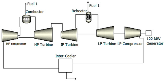
Figure 3.
Schematic of the reheat gas turbine (AGTJ-100A).

Table 1.
A summary of the research efforts on wet compression and spray intercooling with water injection in the compressor.
3.3. Gas Turbines with Recycled Water Injection
The basic gas turbine with recuperation and evaporative aftercooling is shown in Figure 4. This process may be altered by injecting water at a variety of locations during the cycle. The effective and efficient recovery of the energy that is being exhausted by the gas turbine is the key focus. It was observed by Najjar and Zaamout [18] that the fundamental water-injection-based cycle had 58% higher power generation and 13% higher efficiency than recuperation-based configurations that did not include water injection. Figure 4 is a representation of the recuperated water injected (RWI) cycles that Camporeale and Fortunato [19] investigated using a two-shaft industrial gas turbine as the basis for their work. The water-injected cycle produced 30% more power than the simple-cycle gas turbine; the water-injection-based cycle (PRZ16.7, TITZ1250 C) was 44.8% efficient, while the simple-cycle configuration was 32.8% efficient. The water-injected cycle produced 30% more power because the water injection rate was equal to 13% of the input air mass flow rate. When compared to the performance of the basic cycle, the performance of the water-injected cycle was greater in terms of power generation and efficiency at partial load and high levels of temperatures.
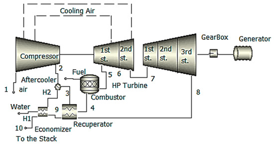
Figure 4.
Schematic of the RWI cycle industrial gas turbine.
The output power and efficiency for an aero-derivative gas turbine were calculated by Camporeale and Fortunato [20] to be 24 MWe and 46.9 percent for a recuperation-based cycle with water injection (PRZ16.3, TITZ1250 C), and 32 MWe and 40% for a cycle with steam injection. According to these numbers, there is a power output of 31.7 MWe, and the efficiency is 41.1%. (PRZ16.3, TITZ1250 C). Additional research on the expander design of water-injected aero-derivative gas turbines was carried out by Camporeale and Fortunato [21]. Intercooling-modified basic cycles are another kind of cycle that has been looked at. The recuperation-water-injection-based cycle and steam-injection-based configurations with and without surface intercoolers were the subjects of research conducted by Manfrida et al. [22]. Because less heat was recovered from the exhaust gas during the water-injected cycles rather than the steam-injected cycles, the water-injected cycles had a lower overall efficiency. In order to achieve a higher rate of heat recovery, the authors suggested using combined cycles that included the introduction of steam from the bottoming cycle into the gas turbine. In order to achieve the highest possible level of efficiency, this system does not inject steam while it is working under base load; nevertheless, when it is working under peak load, steam is injected into the gas turbine in order to boost power generation. The water-injected cycles proved to be the most effective when applied to conditions characterized by low levels of compression and high levels of water injection rates. Because the water injection rates reached up to 20% of the input air mass flow rate, the air in the after-cooler became oversaturated, and the recuperator was responsible for the evaporation of any excess water. According to the assumptions made by Frautschi and Plancherel [23], a water-injected inter-cooled gas turbine would have an efficiency of 43–45%. Chiesa et al. [24] estimated an efficiency of either 52.9% (PRZ33, TITZ1500 8C) or 55.1% (PRZ33, TITZ1500 8C) for an aero-derivative surface inter-cooled water-injection-based configuration (PRZ21, TITZ1250 8C). The use of evaporation as a method of inter-cooling resulted in a marginal reduction in efficiency. The after-cooler received an overabundance of water injection in comparison to what was required for saturation, and the recuperator was responsible for removing the surplus liquid. Traverso and Massardo [25] investigated evaporatively inter-cooled water-injected cycles (water injection cycles [RWI], inter-cooled humid air cycles [HAT], and inter-cooled humid air water injected cycle [AWIT], Figure 5, Figure 6 and Figure 7, respectively) with power outputs of around 50 MWe each.
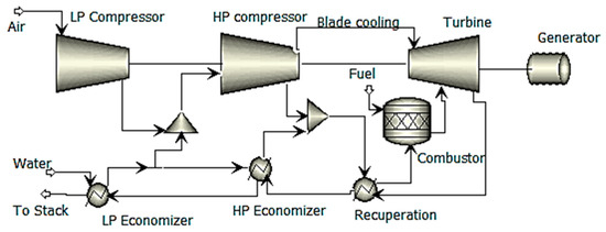
Figure 5.
Conceptual plant design for cycles, including inter-cooled water injection (RWI).
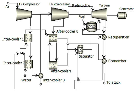
Figure 6.
Cycles of inter-cooled humid air conceptual plant diagram (HAT).
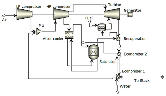
Figure 7.
Conceptual plant diagram for the 3HAWIT cycles of inter-cooled, humid air injection.
The combined cycle, the steam-injected or evaporative gas turbine cycle, and the water-injected cycle all had higher efficiency than the water-injected cycle. This was caused by the air saturation limit on water addition and the high levels of the irreversibility of the air-water-mixing process. Rolls-Royce has investigated the possibility of using a recuperated cycle with a Trent-based engine with water injection for inter-cooling and after-cooling. It was expected that the cycle would have an efficiency of 51%, which is less than a mixed cycle but higher than a basic cycle (42%). The water-injected cycle is expected to offer more flexibility and a particular investment cost that is thirty percent cheaper than that of the combined cycle. Rolls-Royce is of the opinion that there is a large potential for technical risk associated with increasing both the pressure ratio, which is currently set at 35, and the firing temperature; hence, a water-injected cycle is one possibility for improving Trent performance. However, it is projected that the water-injected cycle would have control challenges, and it is also anticipated that the lifespan of the recuperator will be impaired [26].
One such possible modification is the introduction of water into the recuperator of a gas turbine. With an emphasis on inter-cooling and water injection in the recuperators for open-cycle-based power plant configuration, Horlock [27] studied both open/closed water-injection-based gas turbines, as well as water injections in the recuperators for closed-cycle gas turbines. According to [28], the ideal pressure ratio for high efficiency was rather low (i.e., between 8 and 10). Horlock [29] investigated how successful a recuperator would be with water injection either before or during the process of recuperation. El-Masri [30] investigated the effects of injecting water into the intercooler, after-cooler, and recuperator of a two-shaft recuperated gas turbine. This cycle had an efficiency that was 2.75 percentage points higher than a non-inter-cooled steam-injection-based gas turbine and five percentage points higher than a non-inter-cooled water-injection-based recuperated cycle, respectively. Without the water injection, the recuperator would have lost around 2% of its efficiency. According to the author, the evaporative after-cooler was easy to build, and it should be possible for water contaminants to pass through the engine unobstructed.
If water is used at a high level of quality, the water-injection-based recuperator might get polluted. In order to prevent the water’s evaporation from having an impact on the recuperator’s walls, it should be injected as a fine mist. A further possible variant of the fundamental water-injection-based cycle is one in which evaporation and recovery occur in many stages. Research by Annerwall and Svedberg [31] focused on surface inter-cooled reheated power plants with evaporation-based after-cooling, a recuperator, water injection, and a second recuperator. The efficiency reached approximately 53.2%, while the thermal efficiency of a combined cycle was 49.4%, and the thermal efficiency of an inter-cooled recuperated and reheated steam-injection-based cycle was 49.0%. In each cycle, a simple-cycle configuration with a 21,3 MWe power output and a 32.5 percent thermal efficiency was employed (PRZ13.5). Table 2 provides a summary of the key efforts in developing gas turbines with recycled water injection.
Table 2.
A summary of the key efforts in developing gas turbines with recycled water injection.
In addition, Sargent [32] conducted research on a water-injected gas turbine with the goal of using it for district heating and electricity cogeneration. An inter-cooling process with two stages was used throughout this cycle (Figure 8). The injection water was heated during the first step, while external cooling water was utilized during the second stage.
Figure 8.
Scheme of the humid-air heat-and-power plant.
After the compression stage, steam was introduced for after-cooling, the air was recovered once more, and then water heated by the exhaust gas was injected, followed by additional recovery. When compared to single-stage injection, multi-stage injection enabled the incorporation of a greater quantity of water without resulting in the loss of any water droplets inside the recuperator. Because of the large proportion of water in the exhaust gas, the dew point was raised, which resulted in an increase in the amount of heat produced by the district heating system. Szczygiel [33] also studied configurations with a one-stage injection [32] and multi-stage injection [33], with or without an external after-cooler, and extraction of expander cooling air from a variety of cycle points [32].
Alterations to the fundamental idea that are more substantial, such as separating the stream of compressed air for increased heat recovery, have also been proposed. One cycle for the elimination of the low air–water mixing exergy was proposed by Mori et al. [34], and it included the use of direct water injection. The other cycle involved the use of a humidification tower. The process of intercooling was broken down into two phases, and the second stage used a water-cooled intercooler that was a part of the direct water-injected cycle. After passing through the surface after-cooler, the air stream was then segmented into three separate streams, and the second intercooler injected hot water into each of those streams. The resulting humid air streams were mixed and then sent through a second recuperator after being routed in parallel via a first intercooler, an after-cooler, and a recuperator. The original recuperator was not a conventional heat exchanger since it caused water to evaporate. As a result, the cycle that included a humidification tower was considered to be technically more realistic, as indicated in the source [35]. The water-injected cycle that Mori et al. [34] patented was quite similar to the cycle that Nakamura et al. [36] patented, with the exception of one crucial difference; the air supply was divided immediately after the compression stage. In accordance with the cycle outlined by Mori et al. [34], only a part of the stream was sent through the use of the heat-recovery method. The remaining component of the stream was bypassed and instead mixed with moist air before being sent to the third and final recuperator. The efficiency of the humidification system was 50.4% when just 27.9% of the air supply was transmitted through the system, and it was 51.2% when 53% of the intake air was transported through the system. (TITZ1000 8C). A water-injected part-flow cycle that required fewer components was invented and patented by Nakamura [37]. During this cycle, one of the streams that were formed as a result of the split in the compressor was aftercooled evaporatively and reclaimed before being mixed with the stream that contained dry air and went through further recuperation. In addition, patents were granted for a design that used evaporative intercooling and aftercooling for each and every portion of the compressed air. Nakamura [38] demonstrated a recuperation-based gas turbine in which the air supply was inter-cooled in a two-stage approach: initially in a heat exchanger and secondly by injection of intercooler-heated water. This process was carried out in a recuperated gas turbine. In addition to that, hot water was injected into the fuel as well as the compressed air so that it could be after-cooled. Exergy and pinch analysis were used by Bram and de Ruyck [39] in the development of a humidified cycle that was similar to the HAT cycle but did not include a humidification tower. In a similar vein, the procedure described in reference [40] was quite comparable. The fact that the energy from the second inter-cooler was not added back into the cycle was the fundamental distinction between this cycle and the water-injected cycle that Mori et al. [34] developed. The net efficiency of this cycle was equivalent to that of an evaporative cycle that included a humidification tower (54%).
Research has also been carried out on a variety of cycle combinations. A combined cycle with water injection is shown in Figure 9 of Aronis and Leithner’s [41] paper. This cycle was called the low-temperature heat combined (LOTHECO) cycle. Following the gas turbine compressor, the water was fed onto a heat exchanger, where it was subjected to the energy of a low temperature (below 170 degrees Celsius), causing it to evaporate. The low-temperature energy might have originated from the combustion of biomass, the sun, geothermal energy, or even the waste heat from industrial processes. As a result of water rather than air lowering the combustion temperature to the permitted turbine intake temperature, the gas turbine fuel was able to be burned at stoichiometric conditions, which caused a decrease, as a consequence, in the amount of work required for compression. Because the exhaust gas included a significant amount of water, condensation formed at temperatures that were suitable for the district heating system. Alterations to the cycle included super-heating the humidified air or utilizing an external heat source to super-heat the humid air before passing it through the evaporator in order to aftercool the compressed air that was to be used in the evaporator. Dodo et al. [42] created a unique recuperation-based water-injected power unit for the cogeneration of electricity and hot/cold water. An absorption refrigerator is used in this system to capture the energy that is released from the exhaust gas. Depending on the conditions of the working environment, the compressor input might be cooled with cold water from the chiller, or the aftercooling could be achieved with hot water.
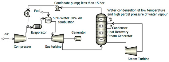
Figure 9.
Simplified plant scheme of the low-temperature heat combined (L.O.T.H.E.C.O.) cycle.
El-Masri [43] developed a cycle in which the temperature of humidified air was increased by flue gas in a heat exchanger while compressed air was aftercooled by water injection. Then, before further recuperation, the humid air was coupled with saturated steam created from the energy of the exhaust gas. The cycle’s efficiency might potentially be improved further by inter-cooling it with water injection. Dual-pressure-combined-cycle configurations were slightly more efficient than the suggested cycle, which was more efficient than steam-injected cycles. Dual-pressure combined cycles were marginally more efficient than steam-injected cycles. Adjustable cogeneration of electricity and steam is made possible by the utilization of a variable amount of the energy contained in the exhaust gas for recovery and steam production. A modified version of the intercooler cycle developed by El-Masri [43] was investigated by Bolland and Stadaas [44] for the purpose of power generation using only the most cutting-edge gas turbines that are now on the market. In this variation of the cycle, the steam is super-heated before it is injected into the combustor. This is in contrast to the traditional cycle, which involves combining saturated steam with moist air prior to the final heat exchanger. For the power units that were put through the study, a steam-injection-based cycle was 9–11% more efficient than a basic cycle, while the suggested cycle was only 3–4% more efficient than a steam-injection-based cycle. The efficiency of big industrial gas turbines was highest with a triple-pressure combined cycle, which ranged from 52–55%, followed by the cycle that was presented (50%), and then a steam-injection-based cycle (44.9–45.9% efficient). The difference in efficiency between a combined-cycle configuration and the proposed configuration was minimal for medium-sized industrial and aero-derivative power units. For small-scale power units (4–6 MWe), the efficiency of the suggested cycle was equivalent to or greater than that of a single-pressure-combined cycle.
According to the published research, there was going to be one demonstration plant in which water was going to be pumped directly into a power unit after the compression stage. This plant was going to be at the Vrije Universiteit in Belgium, and it was going to be used for integrated power production and district heating. In this particular gas turbine, the compressed air was heated using gasified biomass that had been burnt in an external combustor together with the exhaust gas from the gas turbine. This process took place in a metallic heat exchanger. The heat exchanger could boost the air temperature to 800 degrees Celsius, which would make it possible to add natural gas topping combustion and bring the temperature of the turbine input up to 1000 degrees Celsius. It is possible to inject heated water into the external heat exchanger before it is used. This would result in enhanced power production and efficiency, as well as changeable power-to-heat ratios. The calculations showed that the power production would be 300 kW without water injection and topping combustion, while the heat output would be 1200 kW (thermal efficiency 13%, overall efficiency 65%). However, water injection of 8.5% by weight would improve the power output to 565 kWe (efficiency 21.5%). The output would be 800 kWe (with a 26 percent efficiency rate) if water injection and super-heated combustion were used. [45]. Despite this, the authors of this research were unable to find any literature that discussed the operation of this facility in relation to water injection. Bechtel and Parsons [46] received a patent for a similar gas turbine that was water-injected and externally fired, although it did not include topping combustion. Another cycle that has been proposed [47] is known as the VAST cycle, which stands for vapor, air, and steam in combination with a turbine. Despite this, the designer asserts that the cycle circumvents the HAT and evaporative cycles’ saturation restrictions, resulting in higher specific power and reduced costs. The cycle, according to the inventor, also gets over the traditional limitation on water injection brought on by flame stability.
3.4. NOx Management Using the Combustor Injection of Water or Steam
It is possible to lower the amount of NOx that is produced by the combustor by injecting water or steam into it [48]. It was first suggested in the early 1960s [49], and up until the middle of the 1990s [50], it was the NOx control technique that saw the most widespread use. The production of thermal NOx is the principal contributor to the emission of NOx by gas turbines. Because temperature and residence time are the determining factors in the creation of thermal NOx, lowering the temperature of the combustion zone by adding a diluent such as water or steam might result in a decrease in the amount of NOx that is produced [51]. The generation of extra power is an additional advantage of injecting water or steam; however, the efficiency of the process is diminished if the energy from the exhaust gas is not collected and used to warm the water or generate the steam that is injected. Because the required evaporation energy is obtained from the fuel, steam injection impacts efficiency less than water injection; also, for the same NOx reduction effect, less water is needed compared to steam [51]. Water injection has a greater influence on efficiency than steam injection. In most cases, an amount of water equal to about fifty percent of the fuel mass flow rate and an amount of steam equivalent to one hundred to two hundred percent of the fuel mass flow rate are injected [50]. Dry burners that produced minimal levels of NOx were introduced at the beginning of the 1990s. Because of the lean nature of the combustion that takes place in these burners, both temperature and the generation of nitrogen oxides are reduced. Both wet [51] and dry [50] systems have the potential to reach nitrogen oxides levels of 24 ppmvd [parts per million by volume, dry]. Mathioudakis [52] presented a method for conducting an analytical approach to analyze the effects of injecting water into the combustor of a gas turbine on the amount of power produced and the amount of efficiency gained.
4. Water Recovery and Water Quality
In the context of humidified gas turbines, there has been a great deal of discussion on water consumption and quality. The cost of water contributes to an increase in the operating costs of the plant, and water and its impurities have the potential to cause erosion and corrosion in the cycle. It is necessary to make a comparison between the expense of acquiring sufficient-quality makeup water and the cost of installing water-recovery-based systems that both condense and purifies water before it is used again. It is possible for the water to condense either in an indirect surface recuperator that utilizes water (for example, from the environment or cooled by atmospheric air) or in a direct-contact condenser that sprays water into the flue gas [53]. Either method can be used to cool the exhaust gas. Industrial usage of exhaust gas condensation for cogeneration could offer experience with heat and water recovery, which enhances humidifier-based power units. An Italian factory uses a Chang-cycle configuration with a water-recovery technique by an indirect condenser that generates water at high temperatures [54], the steam-injected gas turbine Aquarius recovers water with a direct-contact condenser, and the Swedish evaporative gas turbine pilot plant is water self-sufficient thanks to an indirect condenser [55]. These are just a few examples of how water can be recovered in humidified gas turbines. Figure 10 depicts the flowchart for water treatment that is described in reference [55]. The corrosive substances that might potentially lead to corrosion in the water loop or the power units are removed from the recovered water, and then it is filtered before being reintroduced into the cycle [56].
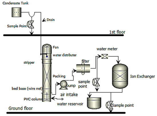
Figure 10.
A flowchart for water treatment in the Swedish evaporative gas turbine pilot plant, illustration of water-recovery techniques in humidification-based power units.
A number of researchers [56,57,58,59,60,61,62,63,64,65,66,67], such as Battegli and Fecchini [59] (direct-contact-condensing technique), Ngayen and dan Ottar [60] (indirect water- or air-cooled indirect condensers), De Peape et al. [58] (water- or air-cooled indirect condensers), and Blanco and Ambs [61] (indirect water- or air-cooled indirect condensers), researchers Desideri and di Maria [64] and references [62,63] (direct-and-indirect air- or water-cooled condensers) have explored water recovery in evaporative cycles (indirect water-cooled condensers). Poels and Galloway [65] investigated the effect that reusing previously evaporated water had on the thermodynamic efficiency of the evaporative cycle. Because of the indirect water-cooling of the condenser, there was a greater pressure drop in the exhaust gas, which resulted in a reduction of 1.2–2.0% in the specific power output and 0.3–0.5% points in the efficiency. Experiments have been performed to see whether it is possible to collect water from humid gas turbine exhaust [67]. In the experiment that De Paepe and Dick [66] constructed, which consisted of a finned-tube condenser, the researchers were successful in recovering all of the water. In addition, a direct-contact condenser was evaluated, and the results showed that it had achieved total recovery [57]. Tests with a condensing glass tube heat exchanger that was put post the HRSG of experimental steam-injection-based power units to avoid corrosion were recorded by Zheng et al. [68]. The condensed water required very little treatment before it could be reused. Cerri and Arsuffi [69] offered an alternative method for achieving the same goal of achieving water independence in steam-injection-based power units. In this particular setup, the energy contained in the exhaust fumes was used to power a demineralizing machine that distilled seawater into water that was suitable for injection. Table 3 provides a summary of the key efforts on water recovery.
Table 3.
A summary of the key efforts on water recovery and water quality.
Pollutants may enter a gas turbine’s cycle along with the intake of air, fuel, and even water in humidified cycles. Gas turbines are susceptible to this kind of contamination. Water that has been demineralized is required for use in gas turbines that use either direct water injection or steam injection. Impurities in the water of poor quality, such as salts, may contribute to corrosions at a high level of temperature components of a gas turbine. These problems can be avoided by using water of higher quality. Evaporative cycles may make use of water of lower quality because only a fraction of the water is evaporated into the air in the humidification tower and because non-volatile contaminants stay in the liquid phase. A model for the movement of alkali salts within an evaporative cycle was suggested by Bartlett and Westermark [70]. The water circuit and turbine blades of a turbine are susceptible to corrosion when alkali metals and alkaline earth metals are present. There is the potential for substances to be transferred between the air and water streams of the humidification tower and the air and water streams of a direct-contact flue gas condenser. If there are pollutants in the water, the only volatile chemicals and compounds that may be delivered to the air are those that are entrained in droplets; as a result, a droplet separator should be installed after the humidification tower. Bartlett and Westermark [71] presented experimental data from the evaporative gas turbine pilot plant that addressed the favorable influence that a variety of input air filters and flue gas condensation had on the air and water quality at the plant. In evaporative cycles that include water recovery, effective intake filters minimize the need for water treatment to a lesser extent. This is because a filter dramatically cuts down on the number of salt particles that are introduced into the cycle. In the absence of an air filter, the water in the humidification tower performs the function of a scrubber, capturing the vast majority of the airborne particles.
5. A Working Fluid for Gas Turbines, Humid Air
5.1. Thermal Characteristics of Mixes of Air and Water
For humidified gas turbines, accurate modeling of cycle performances, design of cycles, and cost estimation necessitate the use of precise thermophysical characteristics for water–air mixtures. This is necessary in order to achieve the desired level of detail. The behavior of the air–water system deviates from what would be considered ideal under certain conditions, in particular when the pressure is high, the temperature is low, and the humidity is high. The references [72,73] analyzed the most recent theoretical models of water–air thermodynamic characteristics and empirical studies. Additionally, these references presented a method for calculating the thermodynamic properties of a mixture of air and water by employing the actual model shown in Figure 11. Dalili et al. [74] investigated the available thermodynamic property models for water–air mixtures and studied the effect of various property models on the modeling of humidified gas turbine cycles. They did this to determine how different property models affect the modeling process. The models that were found had limited temperature, pressure, or humidity ranges, or all three. Despite having a more limited temperature range, the actual gas model [75] developed by Hyland and Wexler was the superior option available (valid up to 200 8C). The real model predicted a larger saturation humidity at a given temperature, which may be explained by the fact that water is more volatile in the real model than it is in the ideal model. This was discovered via a comparison of the data for ideal and actual gases. The efficiency of the cycle seems to be somewhat unaffected by the many thermodynamic models that are considered. Ji and Yan [76] developed a real gas model based on an edited version of the Radlich–Kwang equation of state [77] for the thermodynamic properties (humidity, enthalpy, and entropy) of air–water and nitrogen–water mixtures. This model was supplied as a real gas simulation. The novel model was compared to real-gas models that already existed; up to 45 bars and 390 K, the models were consistent with one another; however, the discrepancies became more pronounced at higher pressures. Ji and Yan [78] validated the novel model by comparing its saturation characteristics to both experimental data and earlier thermodynamic property models for water–oxygen, water–nitrogen, and water–air systems. These comparisons revealed that the novel model accurately predicts the saturated characteristics of these systems. There is not much available empirical information on the water–air system. The comparisons illustrated that the new model could be used for saturation characteristics up to 295 C and 190 atm. The major components of an evaporative cycle were calculated by Yan et al. [79] utilizing ideal, ideal mixture, and actual models, including the Yan–Ji model, for the thermodynamic features of water–air mixtures. These models included the ideal mixture model. The maximum temperature that could be reached at the output of humid air superheater models was 18.8 degrees Celsius. The Ji–Yan model was found to be applicable up to 1500 °C and 200 bar after comparisons of the super-heated features calculated using the ideal model, the Yan–Ji model, and the ideal mixture model.
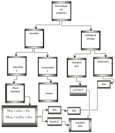
Figure 11.
The calculation approach of thermodynamic properties for the air-water mixture with the real model.
5.2. Humidified Combustion
Because water may induce combustion instability and lower combustion efficiency, which can lead to greater emissions of carbon monoxide and unburned hydrocarbons, combustion can be a possible concern for humidified gas turbines. The sources [80,81] provide a detailed account of the experiments and computations that were carried out to assess the impact that the proportion of moisture in the combustion air had on ignition emissions, operation, and stability limits. The humidified air led to a reduction in NOx emissions, whereas carbon monoxide emissions hardly increased at all. Experimentally, Bhargeva et al. [82] studied humid air premixed flames. The amount of moisture that was present in the air ranged from 0 to 15% by mass. Because of the presence of moisture, the temperature at which equilibrium is reached is lowered, which results in a reduction in the production of NOx. The presence of steam lowers the molar fraction of oxygen and raises the molar fraction of hydroxyl atoms, both of which contribute to a lower overall level of NOx production at an equilibrium temperature that is held constant. This indicates that the decrease in NOx levels was not only caused by the injection of water or steam, which lowered the temperature.
Through a series of calculations and experiments, Harmann et al. [83] studied humidified combustion of methane. It was found that there were relatively low levels of C.O. The authors’ Chan et al. [84] investigated the effect that humid air has on the combustion of liquid fuel in gas turbines. When compared to the situation in which the air was fully dry, NOx emissions may be cut by up to 9% if 1% of steam was mixed with the air at the same flame temperature. This is in comparison to the scenario in which the air was completely dry. The comparison was carried out with the flame kept at the same temperature throughout, and the reduction in NOx was shown to be owing to the identical mechanisms as Bhargava et al. [82] described. Bianco et al. [85] created a simulation of EvGT’s combustion chambers using a premixed flame.
A combustion chamber that was supplied with CH4 and moist air that had a water–air mass ratio of 0–5% was modeled and simulated. Both nitrogen oxides and carbon monoxide emissions were reduced thanks to the addition of water at a constant equivalency ratio. The limit for a lean blowout has been increased, resulting in a larger equivalency ratio. The addition of water increases the mixture’s specific heat capacity, which in turn lowers the flame temperature and thus slows down the chemical reactions that create nitrogen oxides (NOx). Experimental diffusion flame combustors that were fueled with methane and humid air that included up to 20% mass water were the subject of research conducted by Belokon et al. [86].
The data from steam injection was compared to the findings of the experiments that were conducted in an LM5000 combustor. Experiments were carried out so that a model could be developed to forecast the efficiency of combustion as well as the emissions of NOx for humidified air cycles. The evaporative cycle pilot plant’s NOx emissions were below 10 ppm, and the levels of both unburned hydrocarbons and carbon monoxide were at extremely low levels [87,88].
5.3. The Process of Normalizing Data Collected from Gas Turbines for Humidified Gas Turbines
Due to using the methodologies that are now available, normalizing data from gas turbines to ISO standards from a wide range of atmospheric conditions for an evaporation-based power unit was challenging [89]. It is essential that the performance test be carried out on a typical day [87] if the evaporative cycle pilot plant is to avoid experiencing this problem. On the other hand, experimental data from the pilot plant and a system consisting of an artificial neural network were employed in order to construct an empirical model of the cycle. This methodology was employed successfully in order to standardize the data and predict performance [86]. Mathioudakis [90] demonstrated how the results of gas turbine acceptance testing might be modified in order to account for the usage of water injection.
5.4. CO2 Recovery from Humidified Gas Turbines
A significant amount of water is included in the exhaust gases produced by humidified gas turbines. Condensing water results in a decrease in the flow rate of the remaining exhaust gases and an increase in the concentration. This results in a reduction in the cost of removal after combustion as compared to dry gas turbines. Rao and Day [91] conducted research on carbon capturing for the proposed FT4000 HAT power generation unit that would use an advanced combined cycle (triple-pressure, reheat, closed-circuit steam-cooling), as illustrated in Figure 12. Before passing through the recovery unit, which was a steam-driven amine scrubber, the flue gas of the power generation unit was initially cooled in a direct-contact condenser, which caused the water to condense. The HAT cycle resulted in the production of exhaust gas with a high water content; as a consequence, the flow rate in the recovery unit was low, and the concentration was high. As a result, expenses for the carbon recovery unit are lower for the HAT cycle as compared to the combined cycle.

Figure 12.
Block diagram of CO2 recovery in a combined cycle.
When compared to the combined cycle, the HAT cycle with recovery obtained an initial cost savings of 50 USD/kWe, which is equivalent to a 6% reduction. The net efficiencies and power outputs for the HAT cycle with removal were 54.9% (59% without carbon recovery) and 216 MWe, while the net efficiencies and power outputs for the combined cycle were 54.2% and 355 MWe. The researchers hypothesized that if they tweaked the pressure split on the compressor, it would be possible to increase the HAT’s efficiency by two percentage points without removing any . An HAT, an SOFC, and removal were all components of the system that was shown by Rao and colleagues. Due to the fact that the fuel cell operated on pure oxygen rather than air, the exhaust gas was made up of water and carbon monoxide. A direct-contact condenser was used to condense the water; a part of the carbon dioxide was removed while the remaining was feedback to the HAT cycle to regulate the temperature of the SOFC.
The success rate of the cycle was more than sixty percent. Carcasci et al. [92] suggested a partially closed evaporation-based cycle. In this cycle, a portion of the flue gas was feedback, and combustion was conducted at an equivalence ratio of one. This resulted in less effort being exerted by the compressor, and it produced exhaust gas with a high content, which made it possible to remove using techniques that involved absorption.
It was possible for carbon dioxide separation and distribution at atmospheric conditions to achieve an efficiency of more than 50 percent. After passing through the recuperator, the exhaust gas next traveled through devices that absorbed carbon dioxide and recovered water. By combining it with the air from the surrounding environment, some of the exhaust gas was sent back to the compressor. An inter-cooled recuperation-based partially closed gas turbine with water injection for after-cooling and removal by absorption was given a calculation efficiency of 49% by Corti et al. [93]. This included the removal of by absorption. Desideri and Corbelli [94] investigated the possibility of using a Cheng cycle, which was modeled after an already-existing Italian Cheng cycle that had been put into operation in 1991 for the purpose of cogeneration of electricity and district heating and had an absorption scrubber for the removal of carbon dioxide. Emissions of carbon dioxide might be lowered with just marginal improvements in operational efficiencies and electricity generation.
6. Discussion
6.1. Costs and Applications
Because the expenses of the steam turbine are not incurred in the combined-cycle configuration, the specific investment cost for a natural gas-fired humidified cycle should be less than that of a combined-cycle configuration, excluding the cost of development. This is due to the fact that the specific power output is high in the combined cycle. Since the steam turbine contributes a bigger share of the combined-cycle configuration’s investment cost as power output lowers, the difference in specific investment cost should be greater for low-power outputs. This is because the cost of the steam turbine increases as the power output decreases. Part-flow humidification is one option for reducing the specific investment cost in evaporative gas turbine cycles. This is because the area of the heat exchanger and the volume of the humidification tower are both reduced with part-flow, while the electrical efficiencies of part-flow cycles are comparable to or higher than those of full-flow cycles. Because electrical efficiency is the primary factor that determines the cost of energy, the evaporative cycle ought ideally to have an electricity cost that is equivalent to or lower than that of the combined cycle.
Research by Nilson [95], Bartlett [96], and Jonson and Yen [97], as well as the majority of other economic research on the evaporative gas turbine, validates the premise that the evaporative cycle has a lower specific investment cost than the combined cycle. This is the case because the evaporative cycle generates less waste heat than the combined cycle does. However, according to the findings of two studies conducted by EPRI [98,99,100] on the HAT cycle, the individual investment costs for HAT cycles were higher than those for combined-cycle configuration. If a given gas turbine is capable of producing a higher power output (that is, if a higher specific power output can be produced), the particular investment cost will be lowered. The specific power output of the gas turbine has the biggest effect on the particular investment cost. Because of this, the design assumptions that are used to manage the higher mass flow rate of the working fluid that occurs as a direct result of humidification have a significant impact on the total cost of the investment. An increase in the mass flow of working fluid in the expander of the evaporation-based cycle will result in an increase in the specific power output of the evaporation-based cycle and a decrease in the specific investment cost of the evaporative cycle if the compressor size for a particular gas turbine is assumed to be the same for both an evaporative cycle and a combined cycle (if the cost for the gas turbine is assumed to be the same in both cycles). Since the actual design assumptions for HAT cycle gas turbines are not mentioned in the EPRI publications, it is challenging to determine why the specific investment costs for HAT cycles are greater than those for combined cycles.
There are a few different applications for humidified gas turbines, such as the production of base-load power, the cogeneration of electricity and steam, and district heating. Humidified gas turbines perform better than dry gas turbines under conditions of low load and high ambient temperature. This is because the rate at which water is added may be modified to take into account fluctuations in the load as well as environmental parameters [101]. As a result of the liberalization of the power market and the rise of independent power suppliers, there has been a growth in the market for combined cycles that are small to medium in size [101]. Humidified gas turbines should be able to compete with the combined cycle in these markets since deregulated markets need compact, flexible power plants that are capable of producing electricity at a cheap cost. They also have high efficiencies, particular power outputs, and flexibility. When it comes to the cogeneration of electricity and steam or district heating, humidified gas turbines are more adaptable than combined cycles. Additionally, humidified gas turbines have the capacity to provide energy and district heating at a lower cost.
6.2. Development Status
In order for humidified gas turbines to be able to compete with more conventional forms of technology, they need to go through extensive research and development. Although similar on-line compressor cleaning systems are now available for purchase, development for water injection into the compressor for the purpose of inter-cooling (also known as “wet compressors”) is still in the experimental phase. For the purpose of intercooling, water is circulated back and forth between the low-pressure and high-pressure compressors in the LM6000 gas turbine GE Sprint system. Spray inter-cooling seems to be a more cost-effective alternative to surface inter-cooling for the purpose of inter-cooling multi-shaft gas turbines since it requires fewer design alterations than surface inter-cooling does. There are currently no recuperated gas turbines available on the market that include water injection for after-cooling, and the successful functioning of a system like this has not been reported anywhere in the relevant academic literature. The most prevalent use for steam-injected gas turbines is small-to-medium-scale cogenerations for electricity and steam in settings with fluctuating heat demand or electricity prices. This kind of cogeneration may be found in a wide variety of industries. However, steam-injection-based gas turbines that achieve the high efficiency predicted by certain theoretical models have not yet been built. The functioning of the evaporation-based gas turbine cycle has been shown in a pilot plant, but the technology has to be demonstrated on a larger scale in order to evaluate its potential on a more comprehensive level [100,101,102]. It is necessary to find solutions to a number of significant issues before humidified gas turbines may be put into operation successfully. The increase in the compressor back pressure (also known as the pressure ratio) that occurs whenever steam is fed into a gas turbine is a possible source of worry. The rate of injection has to be kept to a minimum in order to maintain a pressure ratio that is below the surge line of the compressor, which represents the upper limit of stable operation. A number of compressor blades have been lodged in the surge region, which causes a reduction in the flow of air between the blades and may lead to flow separation. There is a possibility that some working fluids may rotate in the opposite direction of the rotor, which will result in vibrations that may result in damage to the compressor [50]. The volumetric flow rate mismatch is an additional problem that may arise in humidified gas turbines. The volumetric flow rate of an expander in a gas turbine rises in comparison to the flow rate of the compressor when the working fluid in the gas turbine is humidified. The increased flow might be handled by a gas turbine, such as one that has a compressor from more compact power generation units, but the cost would be substantial, as shown by research on the F.T.4000 HAT power generation unit [100]. Cilsson et al. [102] suggested making use of a free-power turbine or/and dual-spool configurations; nevertheless, this configuration is best suited for use with medium-and-large-sized power generation units. When it comes to the construction of single-shaft gas turbines, a gear may be used between the compressor and the turbine, or a compromise can be found between the design of the compressor and the turbine. Although the flow mismatch problem in commercially available steam-injected cycles has been solved by using partial steam addition or power generation units with broad surge margins, there are still only a handful of power generation units that are capable of operating with total steam injection. It has been suggested to apply the CHAT technique for the evaporative cycle in order to make it possible to make use of regular gas turbine components in a humidified cycle. The problem of flow mismatch may be solved by using the CASH and CASHING cycles, which were first developed for power-producing cycling. When an existing power generation unit is used in the HAT configuration, Reo [103] suggested a HAT cycle in which a part of the humid air is expanded in a separate turbine. This would avoid mismatching of flow rates in the compressor and the turbine that would occur otherwise. Several writers argue that aero-derivative gas turbines are superior to industrial gas turbines when it comes to their ability to function well in humidified cycles. Aero-derivative gas turbines are constructed to accommodate flow rates that are greater than the design value, and their pressure ratios are greater than those of industrial gas turbines. Numerous studies have demonstrated that increasing pressure is advantageous for more efficient humidification-based power generation units. Moreover, the use of an intercooler is made possible by the design of aero-derivative gas turbines that have multiple shafts. Because of the low exhaust gas temperature that is generated by the high-pressure ratio, aero-derivative gas turbines are not as suited for combined cycle applications as industrial gas turbines. This is yet another reason why humidified cycles make use of aero-derivative gas turbines. For this reason, good electrical efficiency in power cycles based on gas turbines requires the use of cycle patterns that are distinct from those of combined cycles.
Another important concern is the research and enhancement of heat exchangers and inter-coolers, both of which are needed for humidification-based power generation units in order to attain the highest levels of efficiency that were determined by this study. Recuperators and intercoolers are not components that are often seen in contemporary power plants. Recuperators for gas turbines are not very popular and have mainly been used for propulsion because of the need to maintain a low specific fuel consumption (kg/kWh) [104]. In addition, recuperators are required for micro gas turbines in order to attain electrical efficiencies that are competitive. Primary surface recuperators [105] and plate-fin recuperators [106] were designed specifically for this use. Saidi et al. [107] conducted tests on a variety of intercooler configurations. An example of an inter-cooled recuperated gas turbine that is utilized in naval propulsive-based applications with decreased fuel consumption is the WR-21 [108]. A component known as the humidification tower is included in the evaporation-based gas power generation units, which were not used before in conventional cycles. Nevertheless, this component finds widespread use in the field of chemical processing. When it comes to the design and development of these components, the sharing of knowledge between mechanical engineers and chemical engineers would be quite advantageous.
The use of humidification in conjunction with the functioning of gas turbines is still another important topic. In the direct water injection and steam injection processes, demineralized water is required. In the evaporative cycle, however, lower-quality water may be used. The use of water drives up operational costs across the board for humidified cycles. It is possible to collect the water that has been removed from the exhaust gas and then reinsert it into the cycle once it has been treated; however, doing so would increase both the initial investment and the ongoing costs. In a number of different installations, it has been shown that it is possible to collect water from the exhaust gas, treat it to a quality where it can be reused in the cycle, and then reuse the water. The cost of obtaining suitable replacement water should be considered while deciding whether or not water should be reused. To prevent the recuperator from being harmed by the evaporation of remaining water droplets, some researchers recommend that the air be partially saturated or under-saturated at the recuperator’s inlet. Other researchers suggest systems where oversaturated air enters the recuperator or systems where additional water is injected inside the recuperator.
The goal of these recommendations is to prevent the recuperator from being damaged by evaporation when air cannot be made to be oversaturated at the recuperator’s input, and the pace at which water is injected is slowed down. The injection of water followed by recovery in many stages is one possibility. When a gas turbine is run on humid air, there is a risk of the combustion becoming unstable, which might lead to a reduction in the efficiency of the combustion process. In spite of this, the evaporative gas turbine pilot plant, as well as other steam-injected gas turbines, have been successfully operated. One of the advantages of using humid air as the working fluid for a gas turbine is that the water in the air lowers the amount of nitrogen oxides (NOx) that are produced during the combustion process. This eliminates the need for an expensive low-NOx burner.
An exhaust gas recirculation (EGR) cycle, a steam injection gas turbine (STIG), and a micro humid air turbine (mHAT) were each subjected to a numerical comparison that was reported by Ali et al. [109]. When compared to the baseline scenario of a recuperated 100 kW MGT, the findings of simulations indicated that the electrical efficiency of humid and steam cycles increased by 6%, but the electrical efficiency of the EGR configuration decreased by 9%. Even though the combustor needed to be improved, the HAT cycle had the greatest performance overall, including in terms of the decrease of NOx emissions.
Micro Humid Air Turbine Plus (mHAT+), Advanced Humid Air Turbine (AHAT), and the REgenerative EVAPoration (REVAP) cycle concept were the three types of humidified micro gas turbines that were studied in De Paepe et al.’s [14] study, which compared the effects of various humidified micro gas turbine concepts on the performance of the plant. The outcomes of simulations run using Aspen Plus show that the REVAP cycle principle may be used to achieve optimum heat recovery, leading to a gain of 4.3% in terms of electrical efficiency.
Using a 30 kWe machine, Lee et al. modeled the impact of water injections directly into the combustion chamber in addition to the impact of water injection in the recuperator intake [110]. According to the simulations, the mGT’s electrical output can be raised (from 22.53 to 29.56 kWe, compared to the 29.67 kWe power output from injection in the recuperator inlet), but the electrical efficiency suffered significantly (a relative decrease of 23.4% compared to the 5.3% increase in the latter case). The key benefit of this application is that, unlike when water is injected before the recuperator, it does not reduce the amount of heat that is available for the generation of thermal power but rather increases it when compared to the dry cycle [110].
The possibility for auto-raised steam injection in a Turbec T100’s compressor outlet was also explored statistically by Ward De Paepe et al. [111], who found that with a maximum injection of 3.3% steam, the electrical efficiency would rise by 5.1% relative [112]. Stathopoulos and Paschereit obtained similar numerical findings while modeling steam injection in the Turbec T100 [113], and [111] ultimately confirmed the results experimentally [114,115].
Athari et al. [116] assessed both the energetic and exergonic performance of GT systems with a STIG cycle (BIFSG) and a combined cycle (BIFCC), with air cooling by fogging and biogas being used in both instances. In contrast to the STIG cycle plant, which is beneficial at low-pressure ratio values, the combined cycle is useful at high-pressure ratios, according to the evaluations. While compared to the combined cycle, the STIG cycle results in a greater net power output and a lower exergy loss for the plant in question when operating under the same circumstances.
Following up on their prior work, the same authors conducted a thermoeconomic analysis of the preceding two systems. According to the findings, the combined cycle generates more electric power at a greater cost per unit than the SI plant does. This also applies to the prices of the individual components [117]. In this research, energetic, exergy, and exergoeconomic assessments were performed in complex systems of GT plants with air cooling and SI; the complexity of these systems raises irreversibilities and costs, which may be optimized if required with more knowledge about where they originated. Exergy analysis at a more advanced level makes it feasible to determine both the source of the destruction (whether it was endogenous or exogenous destroyed exergy) and the greatest potential for improving the systems (whether the destruction was preventable or inescapable).
To summarize the global effort in the field of humidified gas turbines, the Scopus database has been used to feed the VOSviewer software [118] to perform a visualized bibliometric study. The Scopus database was searched to find published “articles”, “abstracts” and “keywords” since 1980 that are related to “Humidified gas turbines”. One hundred and fifty-eight documents have been found in the Scopus database. The results have been exported to the VOSviewer software to generate the keywords network map and the publication rate of each keyword with respect to time, Figure 13.
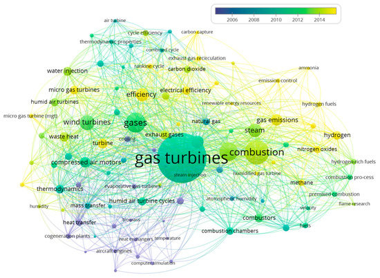
Figure 13.
The network map of the keywords related to “humidified gas turbines”.
The size of the circle of a keyword is determined by the weight of the keyword compared to the other keywords. The higher the weight of the keyword, the larger the label and the circle of the keyword. The color of an item is determined by the cluster to which the item belongs. The distance between two keywords in the visualization approximately indicates the relatedness of the keywords. Figure 14 shows the link strengths of the keywords to each.
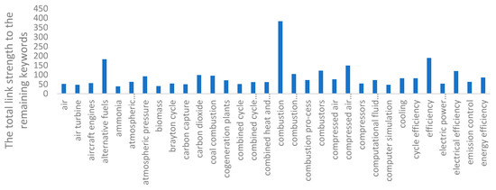
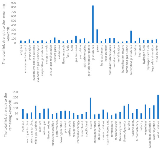
Figure 14.
The link strengths of the keywords to each other (a higher numerical value represents a stronger link to the other keywords).
7. Conclusions
In regard to the findings of the review in terms of thermodynamics: 1. Thermodynamically speaking, humidified gas turbines have the potential to achieve electrical efficiencies that are on par with or even higher than those achieved by combined cycle power plants. 2. The evaporation-based power generation units with humidification towers have shown the highest performance compared to units utilizing other humidification techniques. 3. The specific power outputs of humidified gas turbines are higher than those of dry gas turbine cycles. Those specific power outputs are measured in watts.
The following is a rundown of the findings on the expenses associated with humidification-based power units: 1. The expenses for an established humidified gas turbine ought to be lower than that of a combined-cycle configuration due to the fact that the price for the steam turbine in the bottoming cycle is removed. The expense disparity is more significant for power outputs that are less than their maximum capacity. Evaporative cycles with part-flow humidification are anticipated to have more expenses than evaporation-based cycles with full-flow humidification, while maintaining the same or greater electrical efficiency. This is in contrast to evaporative cycles with full-flow humidification, which is expected to have higher specific investment costs.
From the research that has been completed so far and the applications that have been implemented, we may draw the following conclusions about humidified gas turbines: 1. The only gas turbines now available for commercial use are those that are injected with steam; nevertheless, these turbines do not achieve the high efficiency that was predicted by a number of numerical analyses. The evaporation-based power generation unit was put through its paces in a pilot plant. Still, it seems that the water-injected cycle is the humidified gas turbine cycle that has undergone the least amount of experimental investigation. 2. The mismatch in volumetric flow rates that results between the compressor and the expander is caused by the humidification of the working fluid in the gas turbine. The development of gas turbines that are able to withstand a greater flow rate is still in progress. 3. Humidified gas turbines need inter-cooling and recuperation in order to achieve the highest efficiency levels described in this review article. These levels of performance can only be achieved via these two processes. Additional research and development are necessary before heat exchangers like this may become crucial elements in power generation units. 4. Aero-derivative gas turbines are more suitable for running in humidification-based configurations compared to industrial gas turbines. 5. Numerous power plants have shown that power generation units can function with an -mixed working fluid and that can be retrieved from the flue gases and feedback in the system. This was accomplished by reusing the water that was originally consumed in the cycle. 6. Cogeneration of electricity and district heating is an application that seems to have some promise for humidified gas turbines. Estimates suggest that the separate investment costs, as well as the prices for heat and electricity, shall be much lower than those associated with the combined-cycle configuration. 7. Integrated power generation and carbon dioxide removal are achievable with humidification-based power generation units because the removal equipment may be smaller and, as a result, less expensive than in a mixed cycle. This is due to the fact that humidification makes the gas turbines denser. It is possible that the overall efficiency of the cycle, which would include the removal of , would increase compared to that of the combined-cycle configuration. Finally, nitrogen oxide formation may be reduced by the use of humidification during the combustion process.
Author Contributions
Conceptualization, A.H.A.A., A.A., O.F.A.; methodology, A.H.A.A., A.A., O.F.A.; software, A.H.A.A., A.A., O.F.A.; validation, A.H.A.A., A.A., O.F.A.; formal analysis, A.H.A.A., A.A., O.F.A.; investigation, A.H.A.A., A.A., O.F.A.; resources, A.H.A.A., A.A., O.F.A.; data curation, A.H.A.A., A.A., O.F.A.; writing—original draft preparation, A.H.A.A., A.A., O.F.A.; writing—review and editing, A.H.A.A., A.A., O.F.A.; visualization, A.H.A.A., A.A., O.F.A.; supervision, A.H.A.A., A.A., O.F.A.; project administration, A.H.A.A., A.A., O.F.A.; funding acquisition, A.H.A.A., A.A., O.F.A. All authors have read and agreed to the published version of the manuscript.
Funding
This research received no external funding.
Data Availability Statement
Not applicable.
Conflicts of Interest
The authors declare no conflict of interest.
References
- International Energy Agency. World Energy Outlook; OECD/IEA: Paris, France, 2009. [Google Scholar]
- Jänicke, M. Dynamic governance of clean-energy markets: How technical innovation could accelerate climate policies. J. Clean. Prod. 2012, 22, 50–59. [Google Scholar] [CrossRef]
- Walsh, P.P.; Fletcher, P. Gas turbine performance; John Wiley & Sons: Hoboken, NJ, USA, 2004. [Google Scholar]
- Bhargava, R.; Meher-Homji, C.B. Parametric analysis of existing gas turbines with inlet evaporative and overspray fogging. In Proceedings of the ASME Turbo Expo 2002: Power for Land, Sea, and Air, Amsterdam, The Netherlands, 3–6 June 2002; Volume 4, pp. 387–401. [Google Scholar]
- Rogers, L.H.; Liese, E.A. Humidification of a high pressure air stream by direct water injection. In Proceedings of the 1997 International Joint Power Generation Conference, Denver, CO, USA, 2–5 November 1997; ASME: New York, NY, USA, 1997; Volume 32. [Google Scholar]
- Mohammad, S.; Mohamed, G. Innovative inlet air cooling technology for gas turbine power plants using integrated solid desiccant and Maisotsenko cooler. Energy 2015, 87, 663–677. [Google Scholar]
- Mahmood, F.-G.; Deymi-Dashtebayaz, M. Effect of various inlet air cooling methods on gas turbine performance. Energy 2011, 36, 1196–1205. [Google Scholar]
- Horlock, J.H. Compressor performance with water injection. In Proceedings of the ASME Turbo Expo 2001: Power for Land, Sea, and Air, New Orleans, LA, USA, 4–7 June 2001; ASME: New York, NY, USA, 2001; Volume 78507. [Google Scholar]
- Härtel, C.; Pfeiffer, P. Model analysis of high-fogging effects on the work of compression. In Proceedings of the ASME Turbo Expo 2003, collocated with the 2003 International Joint Power Generation Conference, Atlanta, GA, USA, 16–19 June 2003; Volume 36851. [Google Scholar]
- White, A.J.; Meacock, A.J. An evaluation of the effects of water injection on compressor performance. In Proceedings of the ASME Turbo Expo 2003, collocated with the 2003 International Joint Power Generation Conference, Atlanta, GA, USA, 16–19 June 2003; Volume 3686. [Google Scholar]
- Wang, Y.; Wang, G.; Li, S.; Sun, Y. Analysis of effects on wet compression on surge margin of a small gas turbine. In Proceedings of the 2002 International Joint Power Generation Conference, Scottsdale, AZ, USA, 24–26 June 2002; Volume 36177. [Google Scholar]
- Ingistov, S. Interstage Injection into Axial Compressor, Gas Turbine Model 7EA: Part 2. In Proceedings of the ASME Turbo Expo 2002: Power for Land, Sea, and Air, Amsterdam, The Netherlands, 3–6 June 2002; Volume 36096. [Google Scholar]
- Zheng, Q.; Sun, Y.; Li, S.; Wang, Y. Thermodynamic analyses of wet compression process in the compressor of gas turbine. J. Turbomach. 2003, 125, 489–496. [Google Scholar] [CrossRef]
- De Paepe, W.; Carrero, M.M.; Bram, S.; Contino, F.; Parente, A. Waste heat recovery optimization in micro gas turbine applications using advanced humidified gas turbine cycle concepts. Appl. Energy 2017, 207, 218–229. [Google Scholar] [CrossRef]
- Takeya, K.; Yasui, H. Performance of the integrated gas and steam cycle (IGSC) for reheat gas turbines. J. Eng. Gas Turbines Power 1988, 110, 220–224. [Google Scholar] [CrossRef]
- Hori, A.; Takeya, K. Outline of plan for advanced reheat gas turbine. J. Eng. Power 1981, 103, 772–775. [Google Scholar] [CrossRef]
- de Biasi, V. LM6000 sprint design enhanced to increase power and efficiency. Gas Turbine World 2000, 30, 16–19. [Google Scholar]
- Najjar, Y.S.H.; Zaamout, M.S. Enhancing gas-turbine engine performance by means of the evaporative regenerative cycle. J. Inst. Energy 1996, 69, 2–8. [Google Scholar] [CrossRef]
- Camporeale, S.M.; Fortunato, B. Aero-thermodynamic simulation of a double-shaft industrial evaporative gas turbine. In Proceedings of the ASME Turbo Expo 2000: Power for Land, Sea, and Air, Munich, Germany, 8–11 May 2000; ASME: New York, NY, USA, 2000; Volume 78552. [Google Scholar]
- Camporeale, S.; Fortunato, B. Design and off-design performance of advanced mixed gas-steam cycle power plants. In Proceedings of the 31st Intersociety Energy Conversion Engineering Conference, IECEC 96. Washington, DC, USA, 11–16 August 1996; IEEE: New York, NY, USA, 1996; Volume 2. [Google Scholar]
- Camporeale, S.M.; Fortunato, B. Performance of a mixed gas–steam cycle power plant obtained upgrading an aero-derivative gas turbine. Energy Convers. Manag. 1998, 39, 1683–1692. [Google Scholar] [CrossRef]
- Manfrida, G.; Bidini, G.; Alessandrello, P.P. Exergy analysis of viable options for steam/water injection in gas turbines. In Proceedings of the ASME 1989 International Gas Turbine and Aeroengine Congress and Exposition, Toronto, ON, Canada, 4–8 June 1989; ASME: New York, NY, USA, 1989; Volume 79160. [Google Scholar]
- Frutschi, H.U.; Plancherel, A.A. Comparison of combined cycles with steam injection and evaporation cycles. Proc. ASME Cogen-Turbo II 1988, 137–145. [Google Scholar]
- Bhargava, R.K.; Bianchi, M.; Campanari, S.; Pascale, A.D.; Montenegro, G.N.D.; Peretto, A. High Efficiency Gas Turbine Based Power Cycles—A Study of the Most Promising Solutions: Part 1—A Review of the Technology. In Proceedings of the ASME Turbo Expo 2008: Power for Land, Sea, and Air, Berlin, Germany, 9–13 June 2008; Volume 43178, pp. 305–314. [Google Scholar]
- Traverso, A.; Massardo, A.F. Thermoeconomic analysis of mixed gas–steam cycles. Appl. Therm. Eng. 2002, 22, 1–21. [Google Scholar] [CrossRef]
- Stambler, I. DOE shifting from design studies to technology oriented programs. Gas Turbine World 2002, 32, 17–18. [Google Scholar]
- Horlock, J.H. The evaporative gas turbine [EGT] cycle. J. Eng. Gas Turbines Power 1998, 120, 336–343. [Google Scholar] [CrossRef]
- Fawwaz Alrebei, O.; Amhamed, A.I.; Mashruk, S.; Bowen, P.; Medina, A.V. Planar laser-induced fluorescence and chemiluminescence analyses of CO2-argon-steam oxyfuel (CARSOXY) combustion. Energies 2021, 15, 263. [Google Scholar] [CrossRef]
- Horlock, J.H. Heat exchanger performance with water injection (with relevance to evaporative gas turbine (EGT) cycles). Energy Convers. Manag. 1998, 39, 1621–1630. [Google Scholar] [CrossRef]
- El-Masri, M.A. A modified, high-efficiency, recuperated gas turbine cycle. J. Eng. Gas Turbines Power 1988, 110, 233–242. [Google Scholar] [CrossRef]
- Wang, F.J.; Chiou, J.-S. Performance improvement for a simple cycle gas turbine GENSET––a retrofitting example. Appl. Therm. Eng. 2002, 22, 1105–1115. [Google Scholar] [CrossRef]
- Szargut, J. Cogeneration of network heat in the set of a humid air turbine. Energy 2002, 27, 1–15. [Google Scholar] [CrossRef]
- Ireneusz, S. Thermodynamic analysis of different humid air turbine schemes. In Proceedings of the 15th International Conference on Efficiency, Costs, Optimization, Simulation and Environmental Impact of Energy Systems, Berlin, Germany, 3–5 July 2002; pp. 719–725. [Google Scholar]
- Mori, Y.; Nakamura, H.; Takahashi, T.; Yamamoto, K. IGTC-38 A highly efficient regenerative gas turbine system by new method of heat recovery with water injection (Session A-12 Cycle Performance). In Proceedings of the 1983 Tokyo International Gas Turbine Congress and Exhibition, The International Gas Turbine Congress: Book of Abstracts. Tokyo, Japan, 23–29 October 1983; pp. 297–303. [Google Scholar]
- Fawwaz Alrebei, O.; Al-Doboon, A.; Bowen, P.; Valera Medina, A. CO2-Argon-Steam Oxy-Fuel production for (CARSOXY) gas turbines. Energies 2019, 12, 3580. [Google Scholar] [CrossRef]
- Omar, H.; Kamel, A.; Alsanousi, M. Performance of Regenerative Gas Turbine Power Plant. Energy Power Eng. 2017, 9, 136. [Google Scholar] [CrossRef]
- Nakamura, H. Heat Exchanging System for a Heat Engine. U.S. Patent 4,532,982, 6 August 1985. [Google Scholar]
- Nakamura, H. Heat Exchanging System for a Heat Engine Using Compressed Gaseous Fuel. European Patent Application 0 051 487 A1, 17 July 1982. [Google Scholar]
- Bram, S.; De Ruyck, J. Exergy analysis tools for ASPEN applied to evaporative cycle design. Energy Convers. Manag. 1997, 38, 1613–1624. [Google Scholar] [CrossRef]
- Fawwaz Alrebei, O.; Bowen, P.; Medina, A.V. Parametric study of various thermodynamic cycles for the use of unconventional blends. Energies 2020, 13, 4656. [Google Scholar] [CrossRef]
- Aronis, N.; Leithner, R. Combined cycle with low-quality heat integration and water injection into the compressed air. Energy 2004, 29, 1929–1943. [Google Scholar] [CrossRef]
- Dodo, S.; Tsubouchi, K.; Yasugahira, N.; Arita, H.; Akatsu, Y.; Hatamiya, S. Heat and Electric Power Supply System and Operation Method Thereof. U.S. Patent 6,477,852, 12 November 2002. [Google Scholar]
- El-Masri, M.A. A flexible, efficient gas-turbine cogeneration cycle with a novel dual mode heat recovery system. In Proceedings of the ASME Cogen-Turbo, 2nd International Symposium on Turbomachinery, Combined-Cycle Technologies and Cogeneration, Montreux, Switzerland, 30 August–1 September 1988; pp. 229–237. [Google Scholar]
- Bolland, O.; Stadaas, J.F. Comparative evaluation of combined cycles and gas turbine systems with water injection, steam injection, and recuperation. J. Eng. Gas Turbines Power 1995, 117, 138–145. [Google Scholar] [CrossRef]
- De Ruyck, J.; Peeters, F.; Bram, S.; Allard, G. An Externally Fired Evaporative Gas Turbine Cycle for Small Scale Biomass CHP Production; Report No. CONF-941024-; American Society of Mechanical Engineers: New York, NY, USA, 1994. [Google Scholar]
- Bechtel, T.F.; Parsons, E.J., Jr. Water Augmented Indirectly-Fired Gas Turbine Systems and Method. U.S. Patent 5,165,239, 24 November 1992. [Google Scholar]
- Yu, A.; Su, W.; Lin, X.; Zhou, N. Recent trends of supercritical CO2 Brayton cycle: Bibliometric analysis and research review. Nucl. Eng. Technol. 2021, 53, 699–714. [Google Scholar] [CrossRef]
- Fawwaz Alrebei, O.; Aldoboon, A.; Bowen, P.; Valera-Medina, A. Techno-Economics of CO2-Argon-Steam Oxy-Fuel (Carsoxy) Gas Turbines. Envion. Energy Earth Sci. [CrossRef]
- Dryer, F.L. Water addition to practical combustion systems—Concepts and applications. Symp. (Int.) Combust. 1977, 16, 279–295. [Google Scholar] [CrossRef]
- Bathie, W.W. Fundamentals of Gas Turbines; Wiley: Hoboken, NJ, USA, 1984. [Google Scholar]
- Jonsson, M.; Yan, J. Humidified gas turbines—A review of proposed and implemented cycles. Energy 2005, 30, 1013–1078. [Google Scholar] [CrossRef]
- Mathioudakis, K. Analysis of the Effects of Water Injection on the Performance of a Gas Turbine. J. Eng. Gas Turbines Power 2002, 124, 489–495. [Google Scholar] [CrossRef]
- de Biasi, V. Aquarius design recovers water from exhaust for steam injection. Gas Turbine World 2000, 30, 14–17. [Google Scholar]
- Macchi, E.; Poggio, A. A cogeneration plant based on a steam injection gas turbine with recovery of the water injected: Design criteria and initial operating experience. In Proceedings of the ASME 1994 International Gas Turbine and Aeroengine Congress and Exposition, The Hague, The Netherlands, 13–16 June 1994; ASME: New York, NY, USA, 1994; Volume 78866. [Google Scholar]
- A˚ gren, N.D.; Westermark, M.O.; Bartlett, M.A.; Lindquist, T. First experiments on an evaporative gas turbine pilot power plant: Water circuit chemistry and humidification evaluation. J. Eng. Gas Turbines Power 2002, 124, 96–102. [Google Scholar] [CrossRef]
- Fawwaz Alrebei, O.; Amhamed, A.I.; El-Naas, M.H.; Hayajnh, M.; Orabi, Y.A.; Fawaz, W.; Al-tawaha, A.S.; Valera Medina, A. State of the art in separation processes for alternative working fluids in clean and efficient power generation. Separations 2022, 9, 14. [Google Scholar] [CrossRef]
- De Paepe, M.; Dick, E. Water recovery in steam injected gas turbines: A technological and economical analysis. Eur. J. Mech. Environ. Eng. 1999, 44, 195–204. [Google Scholar] [CrossRef]
- De Paepe, M.; Huvenne, P.; Dick, E. Economic Analysis of Condensers for Water Recovery in Steam Injected Gas Turbines; Report No. CONF-9806214-; Universiteit Gent: Ghent, Belgium, 1998. [Google Scholar]
- Bettagli, N.; Facchini, B. Water recovery in steam injection cycles. In Proceedings of the Florence World Energy Research Symposium, Florence, Italy, 6–8 July 1994. [Google Scholar]
- Nguyen, H.B.; Den Otter, A. Development of gas turbine steam injection water recovery (SIWR) system. J. Eng. Gas Turbines Power 1994, 116, 68–74. [Google Scholar] [CrossRef]
- Blanco, G.; Ambs, L.L. Water recovery systems for steam-injected gas turbines: Size optimization and life cycle savings. In Proceedings of the 2002 International Joint Power Generation Conference, Scottsdale, AZ, USA, 24–26 June 2002; Volume 36177. [Google Scholar]
- Amhamed, A.I.; Qarnain, S.S.; Hewlett, S.; Sodiq, A.; Abdellatif, Y.; Isaifan, R.J.; Fawwaz Alrebei, O. Ammonia Production Plants—A Review. Fuels 2022, 3, 408–435. [Google Scholar] [CrossRef]
- Cataldi, G. Dry Air-Cooling for Water Recovery in Humidified Gas Turbine Cycles. Master’s Thesis, Department of Chemical Engineering and Technology, Division of Energy Processes, Royal Institute of Technology, Stockholm, Sweden, 2001. [Google Scholar]
- Desideri, U.; Di Maria, F. Water recovery from HAT cycle exhaust gas: A possible solution for reducing stack temperature problems. Int. J. Energy Res. 1997, 21, 809–822. [Google Scholar] [CrossRef]
- Poels, R.P.W.; Gallo, W.L.R. A study on water recovery and reuse for HAT (humid air turbine) cycle. In Proceedings of the 2000 ECOS, Enschede, The Netherlands, 3–7 July 2000; pp. 599–608. [Google Scholar]
- De Paepe, M.; Dick, E. Analysis of efficiency and water recovery in steam injected gas turbines. In Proceedings of the ASME 1997 International Gas Turbine and Aeroengine Congress and Exhibition, Orlando, FL, USA, 2–5 June 1997; ASME: New York, NY, USA, 1997; Volume 78705. [Google Scholar]
- Alrebei, O.F.A. Carbon dioxide-Argon-Steam Oxyfuel (CARSOXY) Gas Turbines. Ph.D. Thesis, Cardiff University, Cardiff, UK, 2019. [Google Scholar]
- Zheng, Q.; Wang, G.; Sun, Y.; Liu, S. Experiments on water and heat recovery of steam injection gas turbine (STIG) power plant. In Proceedings of the ASME 1997 International Gas Turbine and Aeroengine Congress and Exhibition, Orlando, FL, USA, 2–5 June 1997; ASME: New York, NY, USA, 1997; Volume 78705. [Google Scholar]
- Cerri, G.; Arsuffi, G. Steam-injected gas turbine integrated with a self-production demineralized water thermal plant. J. Eng. Gas Turbines Power 1988, 110, 8–16. [Google Scholar] [CrossRef]
- Bartlett, M.A.; Westermark, M.O. Modelling of Alkali Contaminant Flows in Evaporative Gas Turbines. In Proceedings of the ASME Turbo Expo 2001: Power for Land, Sea, and Air, New Orleans, LA, USA, 4–7 June 2001; ASME: New York, NY, USA, 2001; Volume 78514. [Google Scholar]
- Zaba, T.; Lombardi, P. Experience in the operation of air filters in gas turbine installations. In Turbo Expo: Power for Land, Sea, and Air; American Society of Mechanical Engineers: New York, NY, USA, 1984; Volume 79498, p. V004T10A009. [Google Scholar]
- Ji, X.; Lu, X.; Yan, J. Survey of experimental data and assessment of calculation methods of properties for the air–water mixture. Appl. Therm. Eng. 2003, 23, 2213–2228. [Google Scholar] [CrossRef]
- Fawwaz Aalrebei, O.; Al Assaf, A.H.; Amhamed, A.; Swaminathan, N.; Hewlett, S. Ammonia-hydrogen-air gas turbine cycle and control analyses. Int. J. Hydrogen Energy 2022, 47, 8603–8620. [Google Scholar] [CrossRef]
- Farnosh, D.; Andrén, M.; Yan, J.; Westermark, M. The impact of thermodynamic properties of air-water vapor mixtures on design of evaporative gas turbine cycles. In Proceedings of the ASME Turbo Expo 2001: Power for Land, Sea, and Air, New Orleans, LA, USA, 4–7 June 2001; ASME: New York, NY, USA, 2001; Volume 78514. [Google Scholar]
- Hyland, R.W.; Wexter, A. Formulations for the thermodynamic properties of dry air from 173.15 K to 473.15 K, and of saturated moist air from 173.15 K to 372.15 K, at pressures to 5 MPa. ASHRAE Trans. 1983, 89, 520–535. [Google Scholar]
- Yan, J.; Ji, X. Humidity, enthalpy and entropy for the humid air form 298 to 573 K and up to 200 bar. In Proceedings of the 16th European Conference on Thermophysical Properties, Orleans, France, 1–4 September 2002; Elsevier: Amsterdam, The Netherlands, 2002. [Google Scholar]
- Ji, X.; Lu, X.; Yan, J. Saturated humidity, entropy, and enthalpy for the nitrogen-water system at elevated temperatures and pressures. Int. J. Thermophys. 2003, 24, 1681–1696. [Google Scholar] [CrossRef]
- Ji, X.; Yan, J. Saturated thermodynamic properties for the air–water system at elevated temperatures and pressures. Chem. Eng. Sci. 2003, 58, 5069–5077. [Google Scholar] [CrossRef]
- Yan, J.; Ji, X.; Jonsson, M. Thermodynamic property models for the simulation of advanced wet cycles. In Proceedings of the ASME Turbo Expo 2003, collocated with the 2003 International Joint Power Generation Conference, Atlanta, GA, USA, 16–19 June 2003; Volume 3686. [Google Scholar]
- Koop, W.E. Advanced Turbine Systems annual program review; No. DOE/METC-96/1023-Vol. 1; CONF-9510109-Vol. 1; USDOE Morgantown Energy Technology Center: Morgantown, WV, USA; USDOE Assistant Secretary for Energy Efficiency and Renewable Energy: Washington, DC, USA, 1995; Office of Industrial Technologies. [Google Scholar]
- Fawwaz Alrebei, O.; Le Page, L.M.; Hewlett, S.; Bicer, Y.; Amhamed, A. Numerical investigation of a first-stage stator turbine blade subjected to NH3–H2/air combustion flue gases. Int. J. Hydrogen Energy 2022, 47, 33479–33497. [Google Scholar] [CrossRef]
- Bhargava, A.; Colket, M.; Sowa, W.; Casleton, K.; Maloney, D. An experimental and modeling study of humid air premixed flames. J. Eng. Gas Turbines Power 2000, 122, 405–411. [Google Scholar] [CrossRef]
- Hermann, F.; Klingmann, J.; Gabrielsson, R. Computational and experimental investigation of emissions in a highly humidified premixed flame. In Proceedings of the Computational and experimental investigation of emissions in a highly humidified premixed flame, Atlanta, GA, USA, 16–19 June 2003; Volume 36843. [Google Scholar]
- Chen, A.G.; Maloney, D.J.; Day, W.H. Humid air NOx reduction effect on liquid fuel combustion. J. Eng. Gas Turbines Power 2002, 126, 69–74. [Google Scholar] [CrossRef]
- Bianco, M.; Camporeale, S.M.; Fortunato, B. Cfd simulation of humid air premixed flame combustion chamber for evaporative gas turbine cycles. In Proceedings of the ASME Turbo Expo 2001: Power for Land, Sea, and Air, New Orleans, LA, USA, 4–7 June 2001; ASME: New York, NY, USA, 2001; Volume 78514. [Google Scholar]
- Belokon, A.A.; Khritov, K.M.; Klyachko, L.A.; Tschepin, S.A.; Zakharov, V.M.; Opdyke, G., Jr. Prediction of combustion efficiency and NOx levels for diffusion flame combustors in HAT cycles. In Proceedings of the ASME Turbo Expo 2002: Power for Land, Sea, and Air, Amsterdam, The Netherlands, 3–6 June 2002; Volume 36061. [Google Scholar]
- Lindquist, T.O.; Rosén, P.M.; Torisson, T. Theoretical and experimental evaluation of the EvGT-process. In Proceedings of the ASME 2000 International Mechanical Engineering Congress and Exposition, Orlando, FL, USA, 5–10 November 2000; ASME: New York, NY, USA, 2000; Volume 19074. [Google Scholar]
- Mesbahi, E.; Assadi, M.; Torisson, T.; Lindquist, T. A unique correction technique for evaporative gas turbine (EvGT) parameters. In Proceedings of the ASME Turbo Expo 2001: Power for Land, Sea, and Air, New Orleans, LA, USA, 4–7 June 2001; ASME: New York, NY, USA, 2001; Volume 78538. [Google Scholar]
- Fawwaz Alrebei, O.; Al Assaf, A.H.; Al-Kuwari, M.S.; Amhamed, A. Lightweight methane-air gas turbine controller and simulator. Energy Convers. Manag. X 2022, 15, 100242. [Google Scholar] [CrossRef]
- Mathioudakis, K. Gas turbine test parameters corrections including operation with water injection. J. Eng. Gas Turbines Power 2004, 126, 334–341. [Google Scholar] [CrossRef]
- Rao, A.D.; Day, W.H. Mitigation of greenhouse gases from gas turbine power plants. Energy Convers. Manag. 1996, 37, 909–914. [Google Scholar] [CrossRef]
- Carcasci, C.; Cosi, L.; Fiaschi, D.; Manfrida, G. Semi–Closed Hat (SC-HAT) Power Cycle. In Proceedings of the ASME Turbo Expo 2000: Power for Land, Sea, and Air, Munich, Germany, 8–11 May 2000; ASME: New York, NY, USA, 2000; Volume 78552. [Google Scholar]
- Corti, A.; Failli, L.; Fiaschi, D.; Manfrida, G. Exergy analysis of two second-generation SCGT plant proposals. In Proceedings of the ASME 1998 International Gas Turbine and Aeroengine Congress and Exhibition, Stockholm, Sweden, 2–5 June 1998; ASME: New York, NY, USA, 1998; Volume 78644. [Google Scholar]
- Desideri, U.; Roberto, C. CO2 capture in small size cogeneration plants: Technical and economical considerations. Energy Convers. Manag. 1998, 39, 857–867. [Google Scholar] [CrossRef]
- Bartlett, M. Developing Humidified Gas Turbine Cycles. Ph.D. Thesis, Royal Institute of Technology, Stockholm, Sweden, 2002. [Google Scholar]
- Sanz, W. Basic Principle. Available online: https://www.diva-portal.org/smash/record.jsf?pid=diva2%3A9236&dswid=4266 (accessed on 2 August 2022).
- Jonsson, M.; Yan, J. Economic assessment of evaporative gas turbine cycles with optimized part flow humidification systems. In Proceedings of the ASME Turbo Expo 2003, collocated with the 2003 International Joint Power Generation Conference, Atlanta, GA, USA, 16–19 June 2003; Volume 3686. [Google Scholar]
- Al-Assaf, A.H.; Alrebei, O.; Amhamed, A.; Hayajnh, M.A.; Fawaz, W.; Al-tawaha, A.S. PID Power Controller to a Setpoint of Fluid Level Height in a Reservoir for Unattended Human Monitoring. Int. J. Electr. Electron. Eng. Stud. 2021, 8, 1–13. [Google Scholar] [CrossRef]
- Rao, A.D.; Francuz, V.J.; Shen, J.C.; West, E.W. A Comparison of Humid Air Turbine (HAT) Cycle and Combined-Cycle Power Plants; Report No. EPRI-IE-7300; Electric Power Research Inst.: Palo Alto, CA, USA; Fluor Daniel, Inc.: Irvine, CA, USA, 1991. [Google Scholar]
- Rao, A.D.; Francuz; Mulato, F.J.; Sng, B.; West, E.W.; Kana, J.; Perkins, G.; Podolski, D. A Feasibility and Assessment Study for FT 4000 Humid Air Turbine (HAT). Final Report; Report No. EPRI-TR-102156; Electric Power Research Inst.: Palo Alto, CA, USA; Fluor Daniel, Inc.: Irvine, CA, USA; United Technologies Corp.: Farmington, CT, USA; Texaco, Inc.: White Plains, NY, USA, 1993. [Google Scholar]
- Božo, M.G.; Vigueras-Zuniga, M.O.; Buffi, M.; Seljak, T.; Valera-Medina, A. Fuel rich ammonia-hydrogen injection for humidified gas turbines. Appl. Energy 2019, 251, 113334. [Google Scholar] [CrossRef]
- Carmona, J. Gas turbine evaporative cooling evaluation for Lagos–Nigeria. Appl. Therm. Eng. 2015, 89, 262–269. [Google Scholar] [CrossRef]
- Corradetti, A.; Desideri, U.; Rao, A.D. A Novel Concept for Combined Heat and Cooling in Humid Gas Turbine Cycles. In Proceedings of the ASME Turbo Expo 2007: Power for Land, Sea, and Air, Montreal, Canada, 14–17 May 2007; Volume 47926. [Google Scholar]
- McDonald, C.F.; Wilson, D.G. The utilization of recuperated and regenerated engine cycles for high-efficiency gas turbines in the 21st century. Appl. Therm. Eng. 1996, 16, 635–653. [Google Scholar] [CrossRef]
- Lagerström, G.; Xie, M. High performance and cost effective recuperator for micro-gas turbines. In Proceedings of the ASME Turbo Expo 2002: Power for Land, Sea, and Air, Amsterdam, The Netherlands, 3–6 June 2002; Volume 36061. [Google Scholar]
- Kesseli, J.; Wolf, T.; Nash, J.; Freedman, S. Micro, industrial, and advanced gas turbines employing recuperators. In Proceedings of the ASME Turbo Expo 2003, collocated with the 2003 International Joint Power Generation Conference, Atlanta, GA, USA, 16–19 June 2003; Volume 3686. [Google Scholar]
- Saidi, A.; Sundén, B.; Eriksson, D. Intercoolers in gas turbine systems and combi-processes for production of electricity. In Proceedings of the ASME Turbo Expo 2000: Power for Land, Sea, and Air, Munich, Germany, 8–11 May 2000; ASME: New York, NY, USA, 2000; Volume 78569. [Google Scholar]
- McCarthy, S.J.; Scott, I. The WR-21 intercooled recuperated gas turbine engine: Operation and integration into the royal navy type 45 destroyer power system. In Proceedings of the ASME Turbo Expo 2002: Power for Land, Sea, and Air, Amsterdam, The Netherlands, 3–6 June 2002; Volume 3607. [Google Scholar]
- Ali, U.; Font-Palma, C.; Hughes, K.J.; Ingham, D.B.; Ma, L.; Pourkashanian, M. Thermodynamic analysis and process system comparison of the exhaust gas recirculated, steam injected and humidified micro gas turbine. In Proceedings of the ASME Turbo Expo 2015, Montreal, QC, Canada, 15–19 June 2015. Paper No. GT2015-42688. [Google Scholar]
- Lee, J.J.; Jeon, M.S.; Kim, T.S. The Influence of Water and Steam Injection on the Performance of a Recuperated Cycle Microturbine for Combined Heat and Power Application. Appl. Energy 2010, 87, 1307–1316. [Google Scholar] [CrossRef]
- De Paepe, W.; Montero Carrero, M.; Bram, S.; Parente, A.; Contino, F. Toward higher micro gas turbine efficiency and flexibility—Humidified micro gas turbines: A review. J. Eng. Gas Turbines Power 2018, 140, 081702. [Google Scholar] [CrossRef]
- Delattin, F.; Bram, S.; Knoops, S.; De Ruyck, J. Effects of Steam Injection on Microturbine Efficiency and Performance. Energy 2008, 33, 241–247. [Google Scholar] [CrossRef]
- Stathopoulos, P.; Paschereit, C. Retrofitting Micro Gas Turbines for Wet Operation. a Way to Increase Operational Flexibility in Distributed CHP Plants. Appl. Energy 2015, 154, 438–446. [Google Scholar] [CrossRef]
- De Paepe, W.; Delattin, F.; Bram, S.; De Ruyck, J. Steam Injection Experiments in a Microturbine—A Thermodynamic Performance Analysis. Appl. Energy 2012, 97, 569–576. [Google Scholar] [CrossRef]
- De Paepe, W.; Delattin, F.; Bram, S.; Contino, F.; De Ruyck, J. A Study on the Performance of Steam Injection in a Typical Micro Gas Turbine. In Proceedings of the ASME Turbo Expo 2013: Turbine Technical Conference and Exposition, San Antonio, TX, USA, 3–7 June 2013. Paper No: GT2013-94569. [Google Scholar]
- Zare, V. Role of modeling approach on the results of thermodynamic analysis: Concept presentation via thermoeconomic comparison of biomass gasification-fueled open and closed cycle gas turbines. Energy Convers. Manag. 2020, 225, 113479. [Google Scholar] [CrossRef]
- Zare, V. Performance improvement of biomass-fueled closed cycle gas turbine via compressor inlet cooling using absorption refrigeration; thermoeconomic analysis and multi-objective optimization. Energy Convers. Manag. 2020, 215, 112946. [Google Scholar] [CrossRef]
- VOSviewer. Available online: https://www.vosviewer.com (accessed on 20 November 2022).


Publisher’s Note: MDPI stays neutral with regard to jurisdictional claims in published maps and institutional affiliations. |
© 2022 by the authors. Licensee MDPI, Basel, Switzerland. This article is an open access article distributed under the terms and conditions of the Creative Commons Attribution (CC BY) license (https://creativecommons.org/licenses/by/4.0/).