1. Introduction
With the rapid development of digital information technology, digital convergence (i.e., integration of a variety of all types of information such as data, voice and video through convergence terminals and services) is expected to lead people to a smart society in which anyone can use personalized services anywhere and anytime [
1]. Unfortunately, the reality is that there is an ever-increasing difference between information communication technology (ICT) infrastructures when comparing urban and rural areas. This is the so-called digital divide, which is mainly due to the business situation where broadcasting and communication operators are reluctant to invest in rural ICT infrastructure, which seems much less profitable [
2].
However, ICT infrastructures could strongly help rural communities and cooperatives where many operations, such as inspection and maintenance, are time consuming, labor-intensive and expensive due to limited access and large distances to cover. For these reasons, new programs are reported in a number of recent studies, and solutions are required in projects relating to rural ICTs for bridging information and service gaps between rural and urban communities (see [
3,
4]).
One of the most attractive solutions, which is widely recognized as promising for filling this gap, is the use of aircrafts without a human pilot aboard, commonly known as unmanned aerial vehicles (UAVs) or drones. Originally produced mostly in military applications, recently they are beginning to be used outside that domain [
5,
6,
7], in large part because they can execute the “dull, dirty, and dangerous” tasks over extended time periods [
8]. According to a recent study [
9], civil UAV drones are now vastly outnumbering military ones, with a market only in the United States that could reach USD$560 million at the end of 2017. Thanks to their versatility, flexibility, easy installation and relatively small operating expenses, they are applied to many scenarios as commercial, scientific, recreational, and agricultural ones. Common applications include search and destroy operations, border surveillance, wind estimation, disaster relief, remote sensing, traffic monitoring and precision agriculture [
10,
11].
In the first period, these various application opportunities have encouraged researchers and developers to focus more on improving the flight efficiency of a single drone. However, in many real-world situations there is a need to develop a drone system that is able to last much longer than the endurance of an individual UAV [
12,
13,
14,
15]. A solution is to use a fleet of small-scale drones combined with methods and algorithms that leverage collaboration between multiple (possibly miniature) drones. This is the case, for example, of the idea in [
16], where the authors proposed a technique of autonomous battery change/recharge stations, which are equivalent to refueling stations. Additional advantages over the use of a single drone are in terms of covered area, load balancing, mission scalability, time efficiency, and fault tolerance.
A number of applications have been proposed for fleets of drones such as managing disaster situations [
17,
18], retrieving information from sensors deployed in areas that are not easy for humans to access, or even transmitting live audio/video from sports events involving fast-moving people, such as bicycle races or skiing competitions.
Of course, employing a fleet of drones as a team requires strong connectivity among drones, as discussed in [
19,
20,
21], where a multi-drone communication platform is defined to support applications that require coordination of multiple drones, and in [
22], where the concept of a flying ad-hoc network (FANET) is introduced as a highly mobile wireless mesh network [
23,
24,
25].
Three elements that can support this trend in the immediate future are cloud computing and the two recent networking paradigms, software-defined networks (SDNs) and networks functions virtualization (NFV). Cloud computing is a new Internet-based computing paradigm that provides shared computer processing resources and data to any device on demand, so enabling ubiquitous, on-demand access to a pool of configurable resources (e.g., computer networks, servers, storage, applications and services) which can be rapidly provisioned and released with minimal management effort. SDNs and NFV, on the other hand, are two paradigms for network softwarization, the first aimed at decoupling the control plane from the data plane [
26,
27], and the second enabling the network infrastructure to be virtualized as building block classes and functions managed by a centralized orchestration entity called management and orchestration (MANO) [
28,
29,
30,
31,
32]. Deployment of SDN has been extensive in fixed infrastructure-based networks, especially in networks within data centers. More recently, both academia and the industry are manifesting increasing interest in application of SDN in dynamic mobile wireless environments [
33,
34,
35,
36,
37,
38]. More specifically, SDN results very suitable for UAV networks where nodes are non-permanent, connectivity is intermittent and channels may be impaired. In this context, SDN is able to easily change flow paths dynamically after topology modifications due for example to link intermittence, or node failures because of battery drainage.
Up to now, at the best of our knowledge, works using both softwarized and non-softwarized networks of drones in an agriculture scenario are limited to sensor applications, where the network is able to gather data from sensors (e.g., soil humidity [
39], gases or smoke from fires, air quality in different layers of the atmosphere [
40], etc.) in order to react with some action like, for example, efficiently spraying pesticides and fertilizers on crops [
41].
Application of a joint SDN/NFV paradigm has led some researchers to overcome the limitation of drone systems developed for specific applications. Authors in [
42,
43] introduced for the first time the idea of integrating UAVs with the cloud, and then in [
44,
45] proposed leveraging on the SDN and NFV to realize a cloud platform for developing drone applications for accessing UAVs through a third party. Drone connectivity scenarios have already been considered in recent 3GPP Release 14 documents [
46], but are limited to consideration of the remote control of drones. A step ahead is done in [
47], which considers the utilization of drones equipped with base stations (BS) to realize a multi-tier drone-cell network to complement the terrestrial HetNets, and propose a management framework based on the SDN/NFV paradigm.
However, one of the main challenges in deploying cloud and fog computing paradigms on fleet of drones is battery duration, since computing hardware is powered by the same energy source of the drone engine: an excessive computing power required by the fog-computing node installed on a drone would compromise its flight duration.
With all this in mind, this paper proposes a video monitoring platform as a service (VMPaaS) for wide rural areas not covered by Internet access. The platform is realized with a FANET, whose target is providing connectivity backbone, and a set of drones equipped with high-resolution cameras, each transmitting a video stream of a portion of the considered area. This platform, thanks to its flexibility due to the application of the cloud/fog and the SDN/NFV paradigms, allows, on the one hand, third-party users to contribute to the whole service by installing new cameras on the area or launching new video-transmitter drones that automatically connect to the platform, and on the other hand, users to connect to the platform and, through their terminal, choose one or more cameras to receive video flows of interest.
The main contributions of this paper are:
- (1)
definition of the platform architecture, which is realized as a “video monitoring as a service” (VMaaS), constituted by a backbone mesh network providing connectivity and computation services to video transmitters, whose selection can be dynamically decided by users according to the portions of rural areas they want to monitor. Specific architectures of both backbone mesh nodes and platform orchestrator are also provided;
- (2)
definition of the service chains to realize the video delivery service; specifically, the paper describes the service chains of both Acquirer and the Edge Streamer nodes;
- (3)
definition of an analytical model to evaluate the computational load of the platform nodes, in such a way so as to allow the network orchestrator to decide the backbone drones where running the virtual functions.
- (4)
application of the proposed model to a case study, in order to analyze the impact of each element of the service chains to the overall computational cost.
The paper is structured as follows.
Section 2 provides an architectural and implementation description of the platform.
Section 3 introduces the service chains defined to realize the platform service.
Section 4 models the computational load of the platform nodes.
Section 5 considers a case study and provides a numerical analysis aimed at showing how the model can be used to design and manage the platform. Finally,
Section 6 draws some conclusions and describe possible future work.
2. Video Monitoring Platform Description
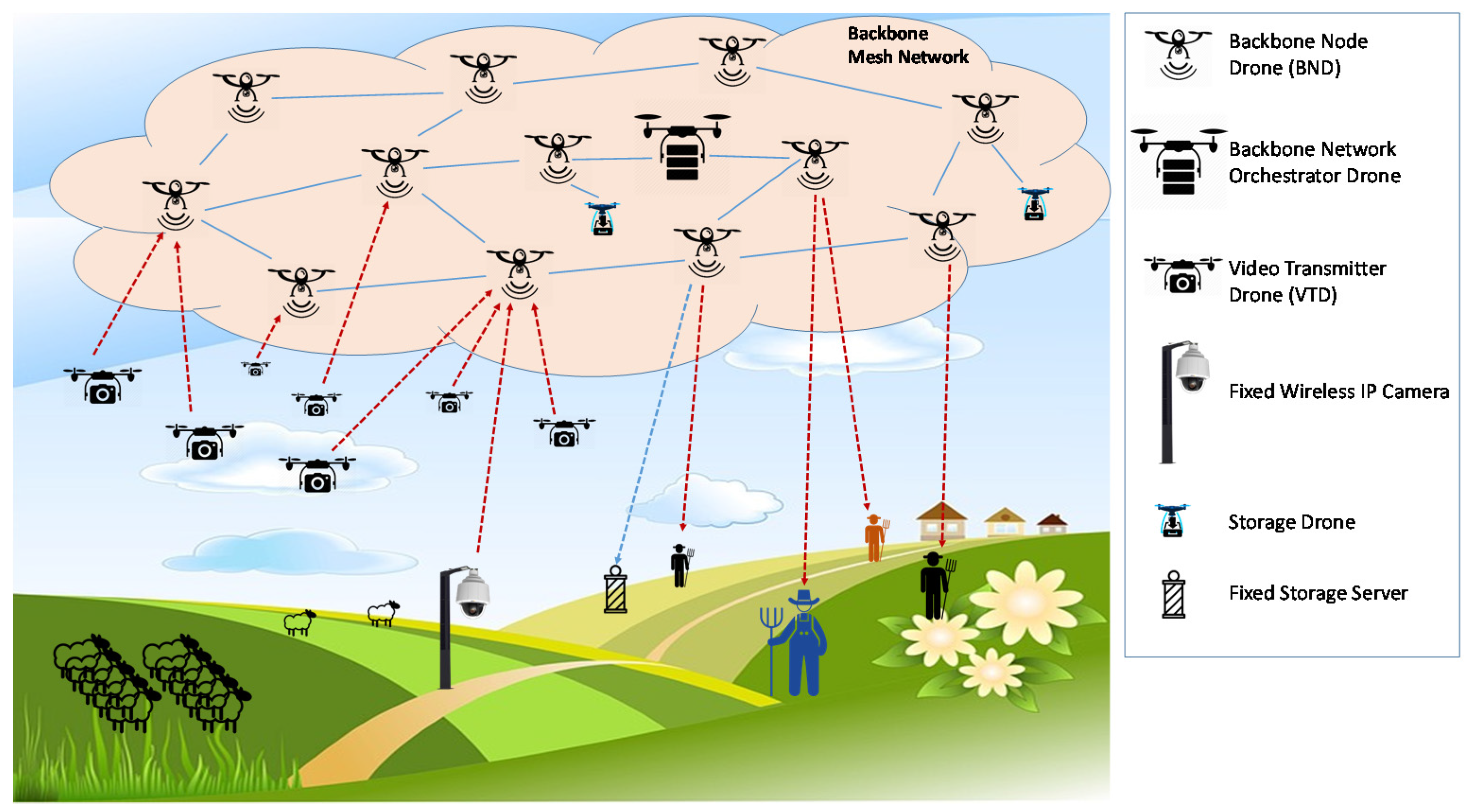
The scenario we refer to in this paper is shown in
Figure 1. It is a rural area where a fleet of drones realizes a video monitoring service for all the people that work there, or have any interest in monitoring it. It is constituted by a wireless mesh network that behaves as a backbone to allow easy and dynamic connections of video transmitter and video receiver devices. As illustrated in the sequel, the proposed platform is designed as a “video monitoring as a service” (VMaaS), which is managed by a video monitoring platform provider. It is not deployed for a specific user, but has the objective of capturing videos of a wide rural area, providing a service that can be used by any customer that has the interest of monitoring one or more portions of it.
The main elements of the video monitoring platform are described in
Section 2.1, while
Section 2.2 presents its architecture. Finally,
Section 2.3 will describe the platform orchestrator, with its management role at both network and application layers.
2.1. Platform Elements
As shown in
Figure 1, the video monitoring platform is constituted by a backbone mesh network and a number of video transmitter devices.
The backbone mesh network, whose nodes are the backbone node drones (BND), is a flying ad-hoc network (FANET), an ad-hoc network that is a particular class of Mobile Ad-hoc NETworks (MANET), also classifiable as a subset of Vehicular Ad-hoc NETworks (VANET) [
34]. Generally, FANETs nodes may be highly mobile, so causing connectivity problems and frequent topology changes. However, for the scenario we are considering in this paper, where the only target is to cover a given rural area, we can assume that they follow a global path plan, that is, all the BNDs slowly move on a predetermined path with a regular mobility model. Moreover, by timely designing of network node density, it is possible to guaranteeing connectivity even in case of failures of some nodes. Therefore, their number, protocols and techniques they apply to setup and maintain connectivity, and the relative routing and battery recharging policies are out of the scope of this paper, and can be considered as a matter of future work. Interested readers can refer to the wide literature regarding FANETs [
23,
24,
25] and data communications in unmanned aerial vehicles (UAV) [
16,
48].
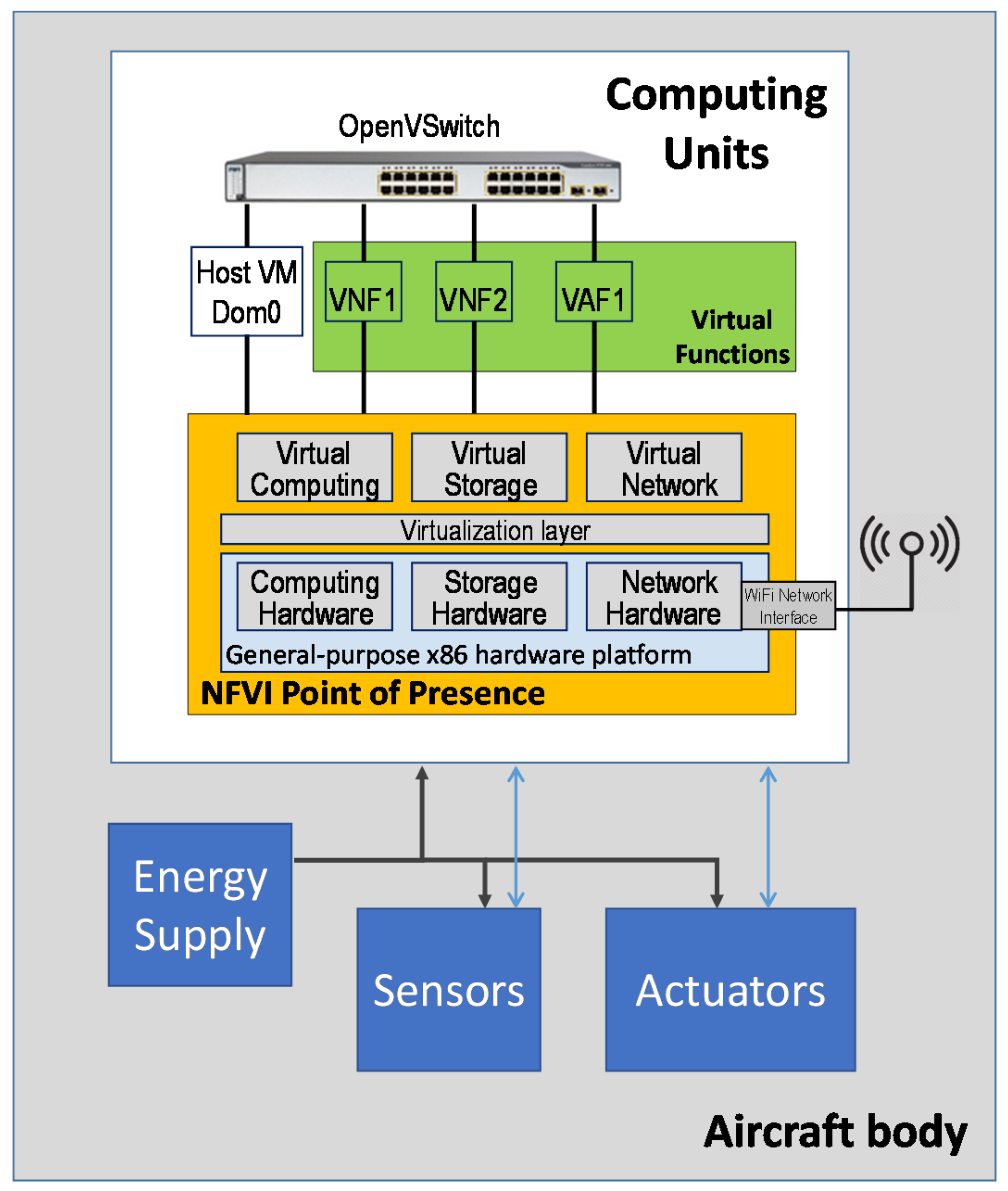
The architecture of the backbone mesh network nodes is presented in
Figure 2. Their target is not only providing connectivity at the network level, but also running the virtual service elements constituting the platform at the application level, that is, the acquirers and the edge streamers comprising the video broadcasting infrastructure described in
Section 2.2. For this purpose, they are equipped with one or more computing units hosting an NFV infrastructure (NFVI) point of presence (POP). A general-purpose x86 hardware, like for example Intel Nuke MiniPC or even RaspberryPi, can be used to deploy a virtualization environment that allows running virtual machines (VM). Each VM is used to host a specific virtual network or application function (VNF and VAF, respectively), according to the NFV paradigm. VM Dom0 is always running to host the operating system. A virtual SDN-compliant software switch (e.g., an OpenvSwitch [
49]) is also installed and run on each backbone node drone to connect local VMs to each other, to the ones running on the neighboring backbone network node drones, and to some transmitter and receiver devices, all under the centralized control of a remote SDN Controller. A WiFi network interface equipped with an omnidirectional antenna allows physical communications in the wireless mesh network.
In our prototype, we used CentOS release 6.4 as host operating system (OS), directly installed on the bare metal, whereas we have chosen Xen Hypervisor [
50] as a VM hypervisor. It behaves as a middleware software, enabling both virtual system management and hardware resource sharing with the aim of executing multiple computer operating systems on the same hardware concurrently. Xen Hypervisor is a free and open-source software developed by the University of Cambridge Computer Laboratory, available for x86-64, IA-32 and ARM architectures, and supporting a form of virtualization known as para-virtualization. Thanks to the para-virtualization paradigm, it is possible to obtain a faster execution of the VMs as compared with the traditional approaches. More in detail, Xen Hypervisor allows virtual machines to share with each other the x86-64 hardware directly, without the need to specify the resources to be allocated for the virtualized hardware preventively. Thanks to this peculiarity, the host OS only acts as a console to operate with the virtualization manager, enabling commands as create, destroy and migrate.
Video transmission is realized with video transmitter drones and fixed wireless IP cameras, all sending video of portions of the considered rural area. Video transmitter drones are drones equipped with high-resolution cameras that dynamically connect to the closest BND to access the video monitoring platform. Fixed wireless IP cameras are video cameras installed on the ground, for example on poles, and likewise video transmitter drones, access the platform through the closest BND.
Receivers of the video monitoring service provided by the above platform are people that, for some reason, need to monitor one or more portions of the rural area. To this purpose, they have a receiver device, which can be either a smartphone, a tablet or a personal computer with a client application installed. From this client application, a user is able to select the rural area portions he is interested to, by choosing them from a map of the area. Moreover, it can be decided to watch a live video stream of the selected areas, recoding it thanks to the storage service provided by the platform, or play out some video stream video stream recorded in the past.
Thanks to the SDN paradigm used by the backbone mesh network, each video flow generated by a video transmitter and entering the backbone network is automatically re-routed to the devices of all the users interested in it. In addition, thanks to the NFV facilities of the backbone, each flow can be elaborated to receive some network and application functions implemented as pieces of software in some drone node of the network, as for example information encryption or event-analysis for alarm triggering setup by the clients.
Let us note that the application of the joint SDN/NFV paradigm allows service continuity even in the case that video transmitters and users change their access point to the backbone network, due for example to movements of users, video transmitter drones and backbone node drones.
2.2. Video Monitoring Platform Architecture
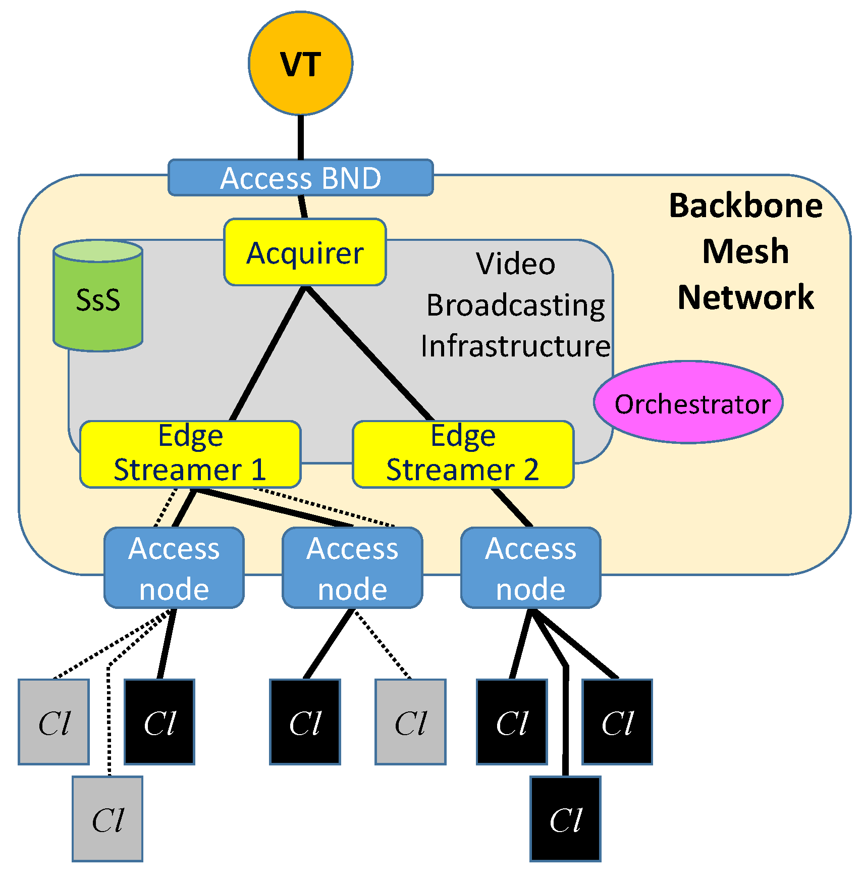
The video monitoring platform architecture is sketched in
Figure 3. It is logically constituted by a Video Broadcasting Infrastructure leveraging on the connectivity service provided by the backbone mesh network described so far. Based on the number of users connected to the platform, and the access points related to their current geographical positions, the video monitoring platform provider sets up and dynamically manages the number of nodes and resources involved in the service. This is done through a softwarized approach based on SDN and NFV.
More specifically, a video delivery tree (VDT) is created for the multipoint video stream generated by each video transmitter. This is a tree structure made up of virtual instances of network and application functions running on the backbone drone nodes, which is responsible for receiving a video stream from a video transmitter and delivering it to the interested end users of the service.
The platform may expose additional functionalities to the end users, such as transcoding of a high-quality video stream to a lower-quality video format in order to fit both end-user and network requirements. If transcoding of the same flow is requested by more than one client, this task is assigned to some of the platform nodes according to the position of the requesting clients. To this purpose, a video delivery forest is realized for each multipoint video stream generated by a video transmitter. A video delivery forest is constituted by one VDT for each quality video format requested by clients for the same flow.
In the platform architecture sketched in
Figure 3, we can see a video delivery forest constituted by two VDTs. In the figure, we can observe a video transmitter (VT) that accesses the backbone mesh network through a backbone node drone (BND) that works as network access point, in order to transmit a given video stream to some interested clients (Cl). In this example, clients access the backbone mesh network through three different access BNDs. Clients shown in the figure belong to two sets, the former requiring the content at the original quality (black clients), and the latter at a lower quality that is achieved by transcoding (grey clients).
Each video delivery forest is constituted by one acquirer and one or more edge streamers. The acquirer is the ingress node of video transmitters to the video broadcasting infrastructure, and represents the root of their VDTs. Its main tasks are recognizing media streams, notifying the orchestrator about the upcoming transmissions, and receiving transmission instructions from the orchestrator in terms of a list of IP addresses of the backbone node drones running the edge streamers where the media streams have to be forwarded. For each flow, the acquirer is run on a VM dynamically instantiated by the orchestrator on an SDN/NFV drone node of the backbone mesh network, in order to be as closer as possible to the relative video transmitter.
The edge streamers are the leaves of the VDTs, and serve the platform clients. Likewise, the acquirers receive instructions from the orchestrator regarding the IP addresses of the clients that have requested to receive the specific flow of each VDT. If only one transcoding quality has been requested, and requesting clients are mobile users accessing the platform through the same network access node, the transcoding function is installed only on the edge streamer running on that node. Instead, if the same transcoding quality is requested by clients assigned to different edge streamers, the relative transcoding function can be installed on either those edge streamers or the acquirer.
Finally, another key element in the proposed platform is the storage sub-system (SsS). Its task is to store video flows. Thanks to it, the platform has the facility of allowing clients to record stream, in such a way that it will be available in the future in off-line mode. More specifically, the acquirer splits video streams, which have to be stored, in sub-streams that can be saved on different drones of the backbone mesh network, named storage drones. In order to increase the storage capacity of the SsS, a set of fixed storage servers are installed on the ground to store old flows that will likely not be requested frequently. In our prototype, the acquirers use Forward Error Correction (FEC) to encode video streams to introduce some redundancy, in such a way that, even if some drones used for storing sub-streams of the same main stream are temporarily not available when a Client request to watch a flow, this flow can be rebuilt. For each flow to be stored, the choice of the number of involved storage drones and fixed storage servers is in charge of the orchestrator.
2.3. Platform Orchestration
A platform element that plays a very important role is the backbone network orchestrator drone, in the following indicated as
orchestrator. It is a dedicated drone communicating with all the platform components through the backbone network. Its goal is to coordinate the behavior of all the elements of the NFV infrastructure (NFVI) [
51], that is, the SDN switches and the virtual machines (VMs) used on the network nodes to run both the network functions and the elements of the video broadcasting infrastructure, i.e., the acquirers and the edge streamers.
More specifically, tasks of the orchestrator are allocating, migrating and terminating VMs, controlling traffic paths, managing and orchestrating service chains according to the run-time evolution of the network traffic, the requirements of the video monitoring platform provider and the service-level agreements (SLAs) with the customers.
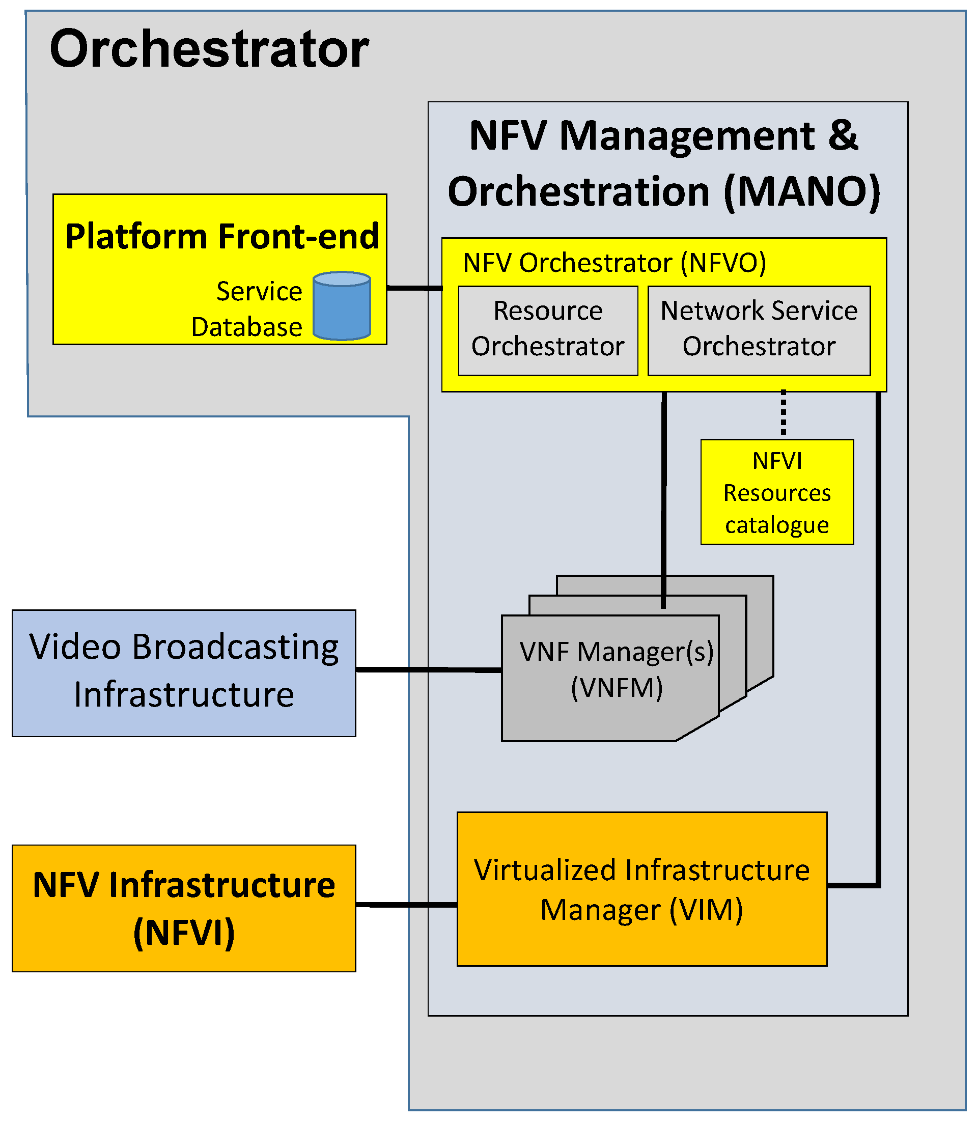
The orchestrator architecture, following the management and orchestration (MANO) document [
28], is shown in
Figure 4. Its main elements are:
- (a)
Platform Front-end: it is the manager of this specific service of video monitoring, and works as the access interface of the orchestrator for the users of this service. The Front-end is an http server aiming at handling the RESTful requests from clients. Application data are stored in a relational database containing the following information:
- ■
Users with their profile and subscription agreements
- ■
For each video transmitter, its geographical position and its access permissions
- ■
For each user, the set of portions of rural to be monitored, the list recorded contents with the location of the stored sub-streams to compose it, and other additional information like the triggering alarms.
When clients access the service through their web-based devices or their dedicated mobile Apps, they directly communicate with the platform front-end, which uses his database, in order to synchronize the information with the local user’s devices. Then, for each action requested by the users, the front-end receives a request and forwards it to the NFV orchestrator residing in the management and orchestration (MANO) segment to be processed and implemented on the video broadcasting infrastructure. More in depth, as a first action, the front-end verifies the user identity. If the entering user is a client, the front-end sends it the list of the available transmitting elements and their current localization on the monitored area. The client can furthermore choose to access his own archive of previously registered contents.
On the other hand, when new transmitting elements are attached to the backbone network, or some transmitter drone changes its current location, the platform front-end notifies this to the NFV orchestrator to reconfigure the mesh backbone network and the video broadcasting infrastructure.
- (b)
Virtualized infrastructure manager (VIM): it is the core application of a softwarized network, acting as a sort of operating system for the network; it sends rules to the hardware and software nodes of the NFV infrastructure about port forwarding, and chooses optimal paths for application data delivery; in addition, it decides the amount of resources, in terms of bandwidth, computing and memory, that each node has reserved to support each elementary service;
- (c)
VNF manager: it has the capability for managing the lifecycle of virtual machines running both network (e.g., deep packet inspectors, load balancers) and application functions (i.e., all the functions related to streaming, forwarding and storage). Its choices are based on the rules and information coming from the NFVO element, and is in charge of creating, migrating and destroying VMs, communicating with the hypervisors running on the network nodes;
- (d)
NFV orchestrator (NFVO): it gathers information about the network (topology, number of connected clients, required contents, availability of backbone node drones, etc.) and, according to specific algorithms and policies, decides how to manage resources of the network devices. More specifically, it has the following main functions:
It is responsible for the implementation of the requests coming from the platform front-end; this is done by configuring and managing the VDTs. More specifically, the NFVO is invoked every time the front-end: (a) receives a connection request from either a client or a video transmitter; (b) a client requests a new connection to a video transmitter; in this case a path has to be created from the video transmitter to it; (c) a video transmitter starts the transmission of a new flow;
It monitors the network status, the usage of wireless links in the mesh network, the RAM/CPU usage of each computation node and each virtual machine running networking or application functions, with the targets of deciding allocation of physical and virtual resources that will be assigned to specific requests, and selecting the most efficient end-to-end paths between video transmitters and receivers.
The policies implemented by the NFVO can refer to a wide range of aspects, like energy consumption, end-to-end delay between source and destination of data flows, number of hops of the path, overall number of virtual machines active at the same time, quality of service (QoS) and quality of experience (QoE), Service Level Agreement (SLA) with the customers, etc. The implemented policies may aim at achieving consolidation, by minimizing the number of drones involved in the forwarding procedure of the media streams from the transmitters to the destination clients. The computational load model described in
Section 4 is one of the key elements to design these policies.
3. Service Chains to Realize the Video Broadcasting Infrastructure Elements
In the proposed platform, each video transmitter is the source of one multipoint video stream that can be transcoded to different qualities and/or stored according to the requests coming from the clients. Consequently, as already said so far, the platform topology can be considered as a forest, that is, a set of trees that have the edge streamer nodes as leaves. More specifically, since each flow can be transcoded at different encoding qualities in different backbone node drones (BNDs), it follows that each flow is transmitted through a forest that is constituted by as many VDTs (transcoded VDTs) as the number of encoding qualities requested for it. The roots of these subtrees are the platform nodes where the transcoders are located. So, given an original flow
f, the flow derived by it with a quality
q will be identified as
, and the transcoded VDT carrying
will be indicated as
. Management policies of the VDTs are in charge of the NFVO block residing in the orchestrator. This is a challenging and very broad topic widely discussed in past and current literature [
52,
53]. Although the whole management problem is out of the scope of this paper, the computational load model described in the following section is a fundamental piece of it.
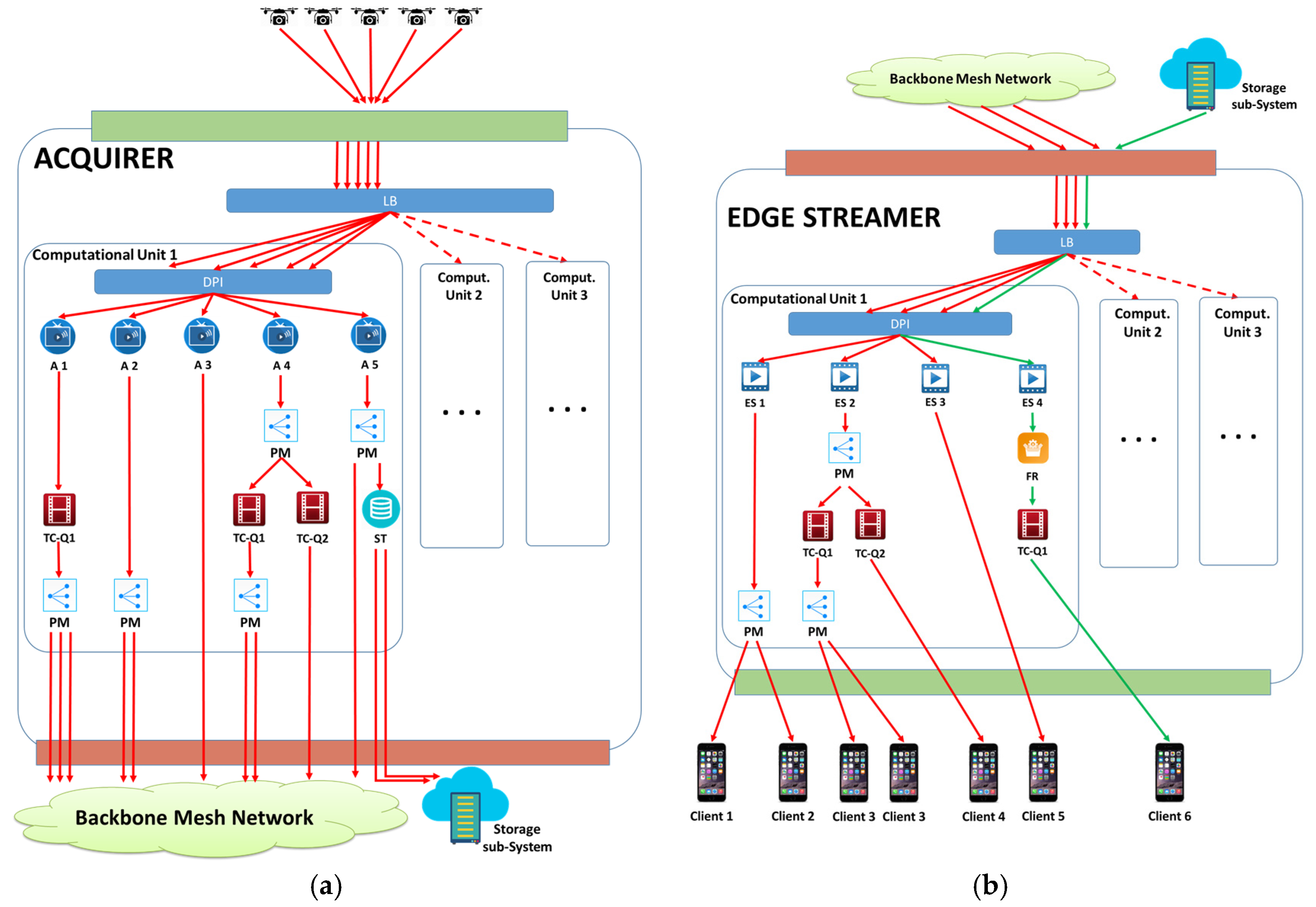
Let us now describe the service chains running in the BNDs to implement both the acquirers, that manage traffic coming from video transmitters towards the platform, and the edge streamers, that manage traffic coming from the platform towards the clients.
The service chain related to the Acquirer is shown in
Figure 5a. Traffic coming from VTs enters a load balancer (LB) block, which subdivides it to the computation units that are currently active in the BND. The number of active computation units and the video flows that have to be managed by each computation unit are decided by the orchestrator that applies consolidation policies in order to concentrate the load on the smallest number of computation units for energy-saving purposes.
When a video flow enters a computation unit, it is first analyzed by a deep packet inspector (DPI) block that forwards it to an acquirer (A) block, which is the root of the relative VDT. Then, if the flow has to be transcoded, it enters the transcoding section, which is constituted by a transcoder (TC) block for each required quality level. If more than one TC is needed for the same flow, the flow is first replicated by a point-to-multipoint (PM) block. Finally, the video flow, either original or transcoded, enters another PM block to create as many copies of the flow as the number of edge streamers that are present on the considered VDT. If some clients have requested to store a flow, a copy of it is created by another PM block and sent to the storage (ST) block. This last block saves only one copy of each video flow if at least one recording request has arrived to the system, and even if more than one recording requests have been received by the orchestrator for the same flow. In order to limit the unavailability probability of the drone where the flow is saved, the ST makes a FEC encoding [
54], splitting the flow in
M different parts such that, if any
F of them, with
, are available, the flow can be rebuilt. The flow parts are then sent to
M different storage drones or fixed storage servers to be saved. The numbers
M and
F, and the IP addresses of the
M different storage elements are provided to the ST block by the orchestrator.
The service chain of the edge streamer nodes is represented in
Figure 5b. In these nodes, flows arrive from acquirers through the backbone mesh network, specifically by the acquirers that have some children in the considered edge streamer node. Focusing on a specific flow, which can be either with the original quality or a quality
q obtained for transcoding, it is first managed by a LB block and a DPI block with the same functionalities explained so far when we referred to
Figure 5a. Then, the flow arrives to the edge streamer (ES) block, which is the block that is in charge of the communications with all the clients assigned to it. Finally, as in the acquirer nodes, the video flow enters the transcoding section if transcoding is required in this node, and then in the point-to-multipoint section to be replicated to all the clients that have to receive it. Moreover, if some client requires watching a stored video flow, its ES requests the component sub-flows to
F storage drones decided by the orchestrator, in order to reassemble it, and passes the received parts to the flow rebuilder (FR) block, which creates again the flow with the original quality, applying an inverse FEC. Then the flow traverses a transcoding section if transcoding is needed, and finally is delivered to the requesting client.
4. Computational Model of the Backbone Node Drones
In this section, considering the service chains described above, we model the computational load of the backbone node drones hosting the platform elements. Let us note that each drone can be, at the same time, the ingress node for some VTs and the egress node for some clients. For this reason, limiting our attention to the traffic related to the considered platform, in the generic backbone drone the total network traffic is the sum of the traffic entering from the VTs (for the acquirer role of ) and the traffic entering from the other backbone drones, to be forwarded to the clients (for the edge streamer role of ).
The overall computational load of the generic drone
is:
where
and
are the computational loads related to the acquirer and the edge streamer roles, respectively. They can be calculated as the sum of the contributions due to each element of the service chains shown in
Figure 5:
where each element, representing the computational load of all the blocks depicted in
Figure 5, will be defined in
Section 4.1 and
Section 4.2.
The components of the acquirer computational load will be derived in
Section 4.1, while the ones related to the edge streamer will be derived in
Section 4.2.
Following the literature [
55], we model the load of a VM hosting a virtual function with a linear model constituted by a base part needed to maintain the VM active, and a part proportional to the managed traffic. Therefore, in the following, for the generic VM
v hosting the generic virtual function
V, we will indicate the base computational load needed to run
v as
, and the computational load per unit of flow related to the virtual function
V as
.
4.1. Acquirers
Let us consider the service chain related to the acquirer running in the generic drone
. Let
be the number of VTs attached to
. Referring to
Figure 5a, the whole acquirer computational load is the sum of the loads related to all the blocks highlighted in that figure, as expressed in (2).
According to the linear model of the computational load, the computational load of the load balancer is:
where
is the bit rate of the flow
f.
The computational load for the deep packet inspectors can be calculated taking into account that we have one DPI for each computation unit that is active in the drone
, and the whole traffic coming from the VTs is distributed to the DPI blocks of the active computation units. Therefore, the overall computational load due to the DPI blocks is:
where
is the number of computation units in the considered drone
.
In order to calculate the computational load due to the acquirer blocks, notice that we have an instance of the acquirer block for each entering flow, and therefore:
Let us now derive the computational load due to the point-to-multipoint (PM) blocks. For this purpose, let us note that we have two sets of PM blocks. The first set is constituted by PM blocks that replicate flows to be sent to the transcoders if they have to be transcoded. More in depth, we have one PM block for each flow
f that has to be transcoded in the considered drone
, event represented by the indicator function
defined as follows:
The generic PM block of this set, the one that manages the generic flow
f, is loaded by a bit rate
, and has a computational load per unit of flow,
, that depends on the number of replicas it has to do, that is equal to the number
of transcodings that the drone
has to do on the flow
f, plus one if it has been requested the storage of the flow. In order to represent this last event, let us define the following indicator function:
The second set is constituted by the PM blocks that create replicas of the flows for the edge streamers in the related VDTs. To this purpose, for the generic flow
that has to be forwarded by the drone
to some edge streamers at an output quality
, we indicate its bit rate as
, and define the indicator function
as follows:
Each of these last PM blocks has to manage a flow bit rate
and has a computational load per unit of flow,
, that depends on the number of replicas it has to do, that is equal to the number
of edge streamers nodes on the related VDT
. Therefore, we have:
where
is the number of possible quality levels, and
indicates the original quality, that is,
.
The computational load due to the transcoder (TC) blocks can be derived taking into account that we have one TC block for each flow that has to be transcoded, and for each requested encoding quality, that is:
where we have considered that the parameter
depends on the out transcoding quality, as noted experimentally. The function
in (11) is an indicator function of transcoding at the specific quality level
, defined as follows:
Finally, the computational load due to the storage (ST) blocks depends on the bit rate of the flows to be stored, and therefore we have:
4.2. Edge Streamers
According to (3), let us derive the computational load due to the edge streamer chain, as represented in
Figure 5b.
In order to evaluate the computational load of the load balancer, let us observe that this block is loaded by a traffic bit rate given by the sum of two terms, the first related to the live streaming flows coming from the acquirers, and the second related to the stored flows requested by the clients connected to the considered edge streamer.
The first term is the aggregated bit rate of all the live streaming flows directed to the clients accessing the platform through the edge streamer running in the considered drone
. In order to calculate it, for a generic live streaming flow
encoded at a quality level
, let us define the indicator function
of the fact that the considered edge streamer in the drone
is on the VDT
, that is, some clients connected to the platform through the drone
have requested to receive the flow
at quality
. Thus, this function is defined as follows:
On the other hand, the second term can be calculated as the sum of the bit rates of the stored flows requested by clients connected to the platform through the drone
. To this purpose, for a generic stored flow
, let us define the following indicator function:
The total input bit rate of the ES node in the drone
is:
where
is the set of stored flows, and
the bit rate of the stored flow
. Now, we can calculate the computational load of the load balancer block as follows:
The computational load of the DPI block can be calculated as in (5), taking into account that in this case the input bit rate is
. Therefore, we have:
In order to calculate the computational load of the edge streamer (ES) blocks, we note that we have one ES for each live streaming flow crossing the drone
, and an additional ES for each client that has requested to watch a stored video stream. Therefore, we have:
Let us now derive the computational load for the point-to-multipoint (PM) blocks in the edge streamer of the drone
. It is the sum of two terms: the first one considers the PMs used to send the video flows to the transcoding blocks and, for a given flow
, it is present if this flow has to be transcoded to at least two quality levels; the second term accounts for the point-to-multipoint transmission of each flow to more than one client. Therefore, if we indicate the number of clients connected to the VDT
through the edge streamer in the drone
as
, and define the following indicator function:
we have:
The computational load of the flow rebuilder (FR) block can be easily derived considering that the edge streamer node
has one FR for each stored flow requested by clients connected to this node. Therefore, we have:
Finally, the computational load of the transcoder (TC) blocks can be derived considering all the flows that should be transcoded in the edge streamer, that is, both the live streaming flows and the stored flows. Therefore, if we indicate the generic live streaming flow as
, and the generic stored flow as
, we have:
5. Numerical Results
In this section, we consider a case study constituted by a fleet of forty drones covering a wide rural area, and working as nodes of the backbone mesh network, all equipped by an SDN/NFV infrastructure to host virtual functions for the video monitoring service. As said in
Section 2.1, protocols and techniques applied to setup and maintain connectivity are out of the scope of this paper, and therefore we are limited to assuming that the FANET supporting the backbone mesh network guarantees connectivity with the required throughput between each pair of adjacent nodes.
Each backbone node drone carries a package of five Intel NUC Mini PC with processor INTEL i5-3330 @ 3.00 GHz, 64 bits. The monitoring network is constituted by 50 fixed wireless IP cameras installed in strategic points on the territory, and powered with solar energy, and a number of video transmitter drones flying on the same area to integrate video covering of the considered rural zone; this last number has been varied in our numerical analysis in the interval between 0 and 150, in order to have a total number of video transmitters ranging between 50 and 200. Some additional nodes complete the network, one working as backbone network orchestrator drone, four as storage drones, and two installed on the ground to work as fixed storage servers.
We have realized two different analyses. In the first analysis, we have varied the number of video transmitters as indicated so far, i.e., in the range [50, 200], while, in the second analysis, we considered a constant number of video transmitters, set to 200, and we varied the number of acquirer nodes active in the network. In our study we assumed that one-third of the video transmitters encode video at 400 kbit/s, one-third at 500 kbit/s and one-third at 600 kbit/s. The number of video receivers for each video transmitter has been randomly chosen in the set [
1,
5]. Moreover, 10% of video flows are requested to be recorded.
Video receivers can set the destination quality with different levels, the lowest corresponding to a bit rate of 50 kbit/s, and the others with an increment of 50 kbit/s, so ranging between 50 kbit/s and 300 kbit/s. We assumed that 30% of the clients are able to receive video at the maximum quality, while the remaining ones require a quality levels randomly chosen among the six available ones.
In the first analysis, we have considered the presence of 5 acquirers and 10 edge streamers, whose position in the backbone network is decided by the network orchestrator to minimize their average distance from the video transmitters and the video receivers, respectively. Obtained results are averaged on 200 simulation runs, each characterized by a different position of the video transmitter drones, chosen in a random way. Parameters characterizing the computational load of each virtual function have been derived experimentally by running them on virtual machines created with 1 core, a RAM of 1024 MB, and a storage space of 5 GB, and using an Ubuntu operating system with Java and gcc. Each virtual machine in idle state uses 0.1% of the processor. The measured parameters are listed in
Table 1.
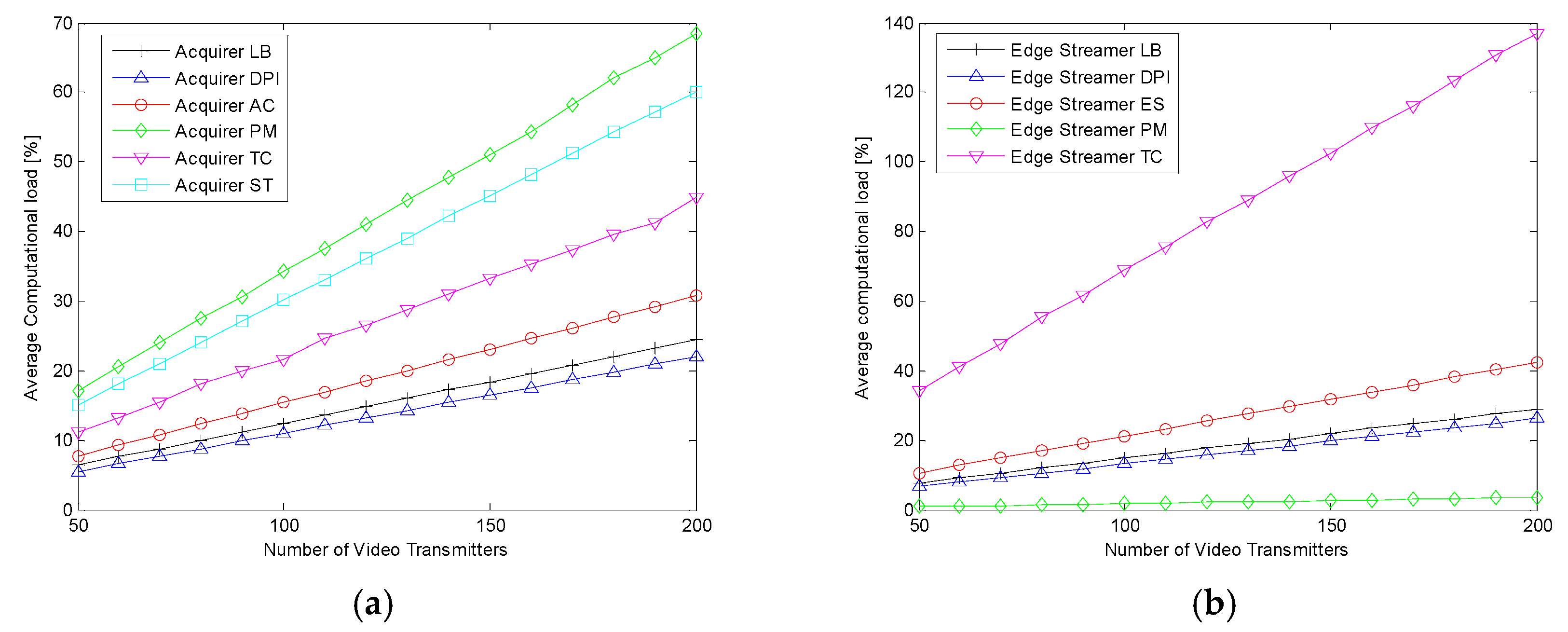
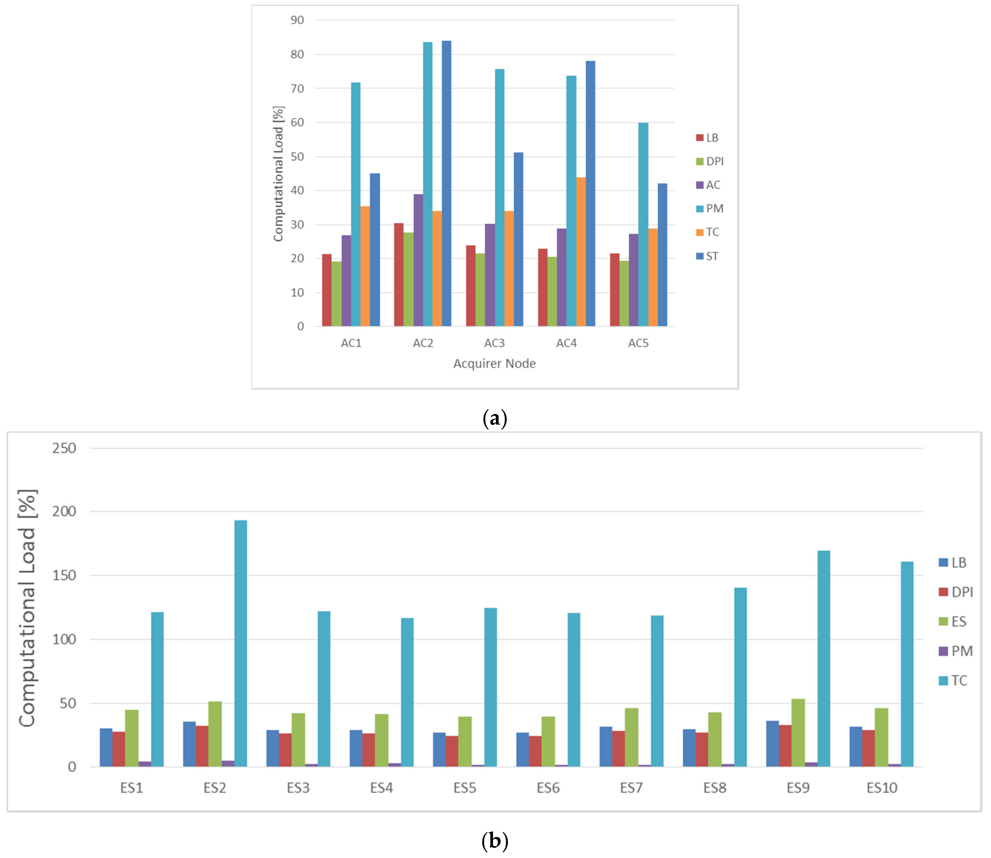
In order to evaluate the contribution of each virtual function to the overall computational load, in
Figure 6 we show their computational loads averaged over all the drones hosting them. As expected, they increase in both the acquirers (see
Figure 6a) and the edge streamers (see
Figure 6b) with the number of video transmitters. Moreover, we can observe that the PM block is the most CPU-hungry in the acquirers, while it occupies the least portion of CPU in the edge streamers. The first reason is due to the high number of edge streamers, each requiring a copy of each flow, copies that have to be created in the acquirers. The second reason is related to the presence of the transcoding function, which is mostly put on the acquirers because, for the majority of the flows, there are clients requesting the same quality level and attached to different edge streamers; in this case, the transcoders are put on the root of the tree, that is, on the acquirer.
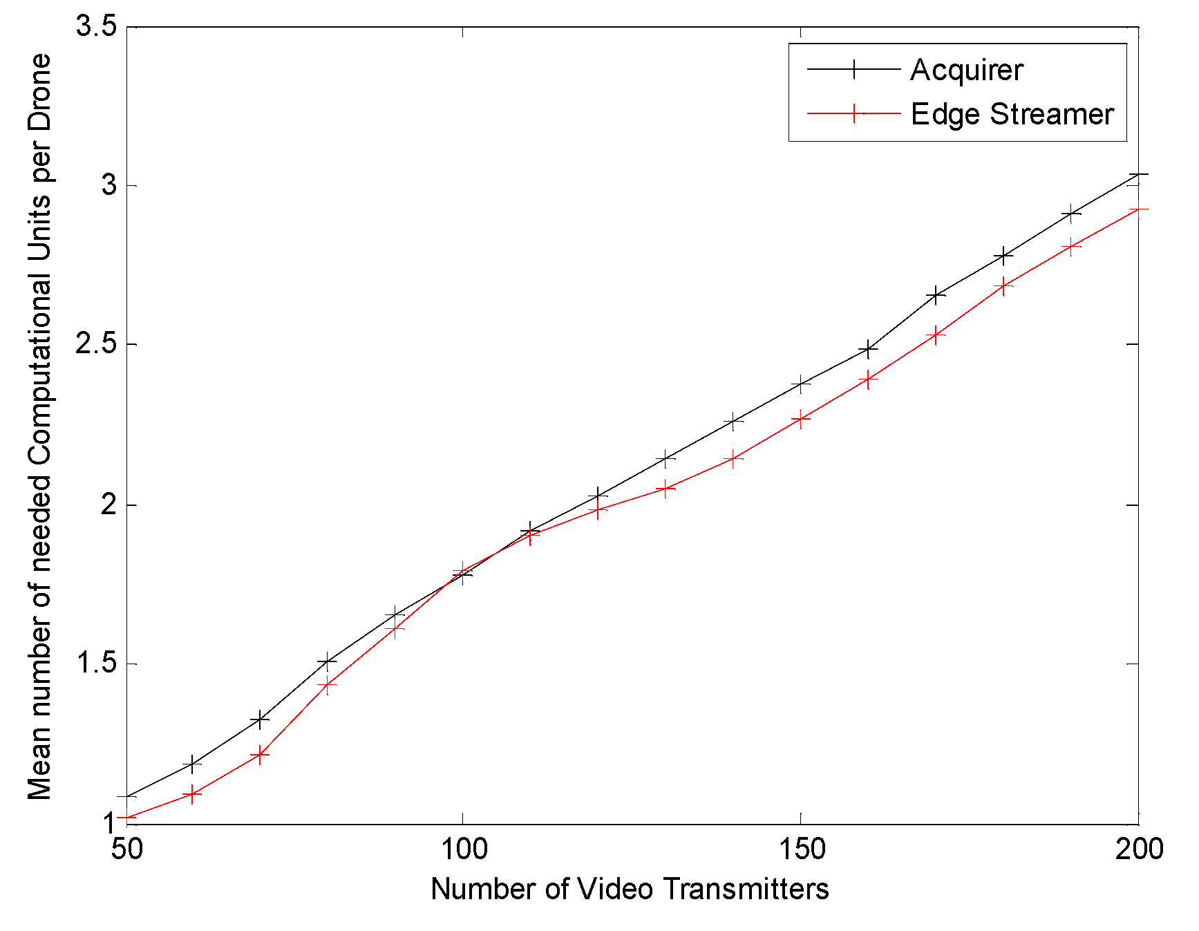
The model proposed in the paper can be used by the orchestrator to evaluate, and then optimize, the number of computation units to activate on each drone. For this reason, we have presented in
Figure 7 the mean value of the number of active computation units needed in each drone.
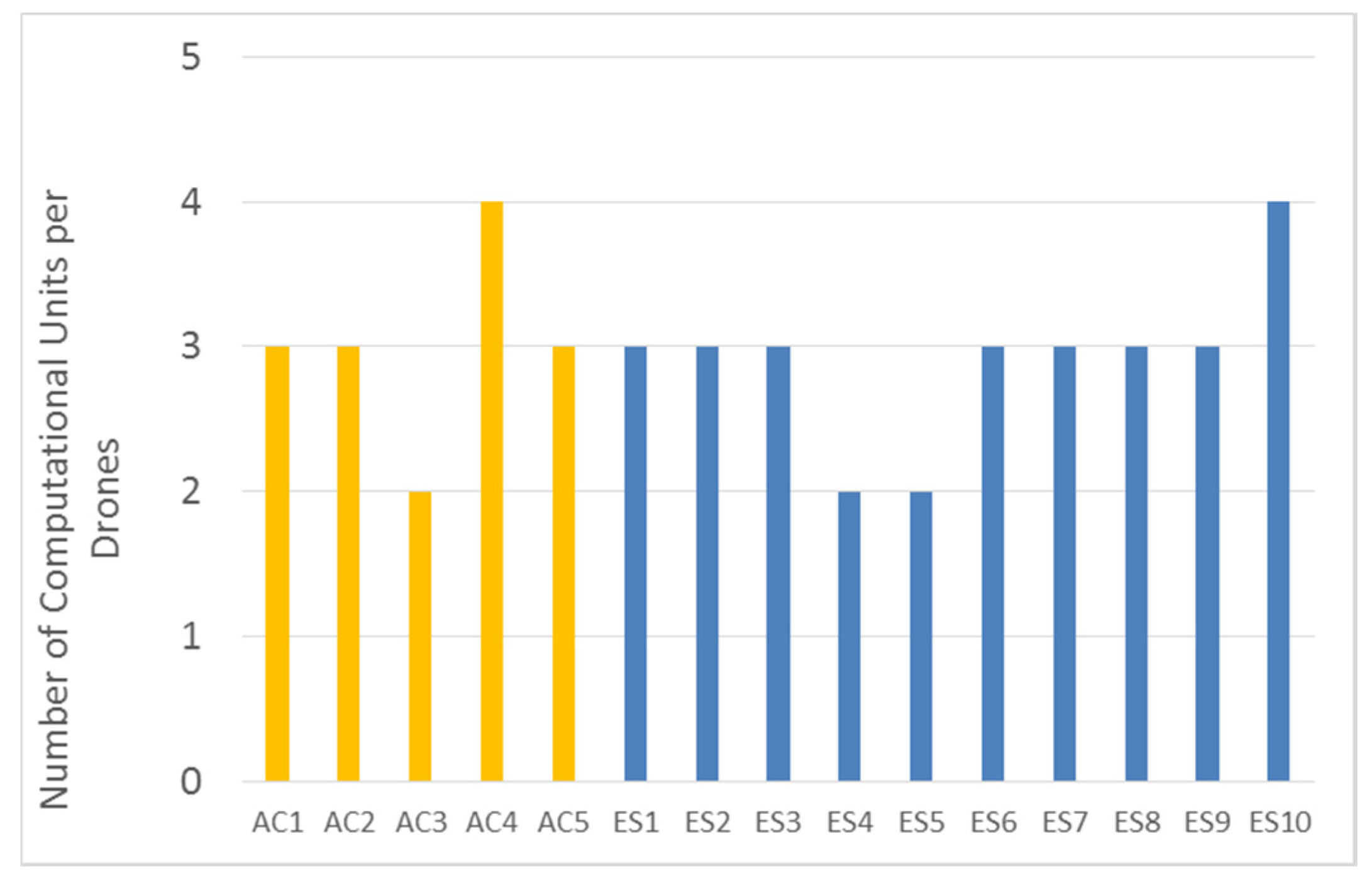
In order to show the total information that is available to the orchestrator for its decisions, we have analyzed a specific situation where the rural area is covered by 200 video transmitters, i.e., 50 fixed cameras and 150 video transmitter drones, connected to the backbone mesh network with a fixed topology.
Figure 8 shows the detailed computational load in the acquirers and in the edge streamers, while
Figure 9 summarizes the number of needed computation units in each acquirer and in each edge streamer to support the load, taking into account that each computation units can support at most a load of 100%. Using this information, the orchestrator can decide to switch off some backbone drones, or switch on some of them to migrate on it some virtual function in order to decrease the load of other drones that need to save some energy to extend their flight life.
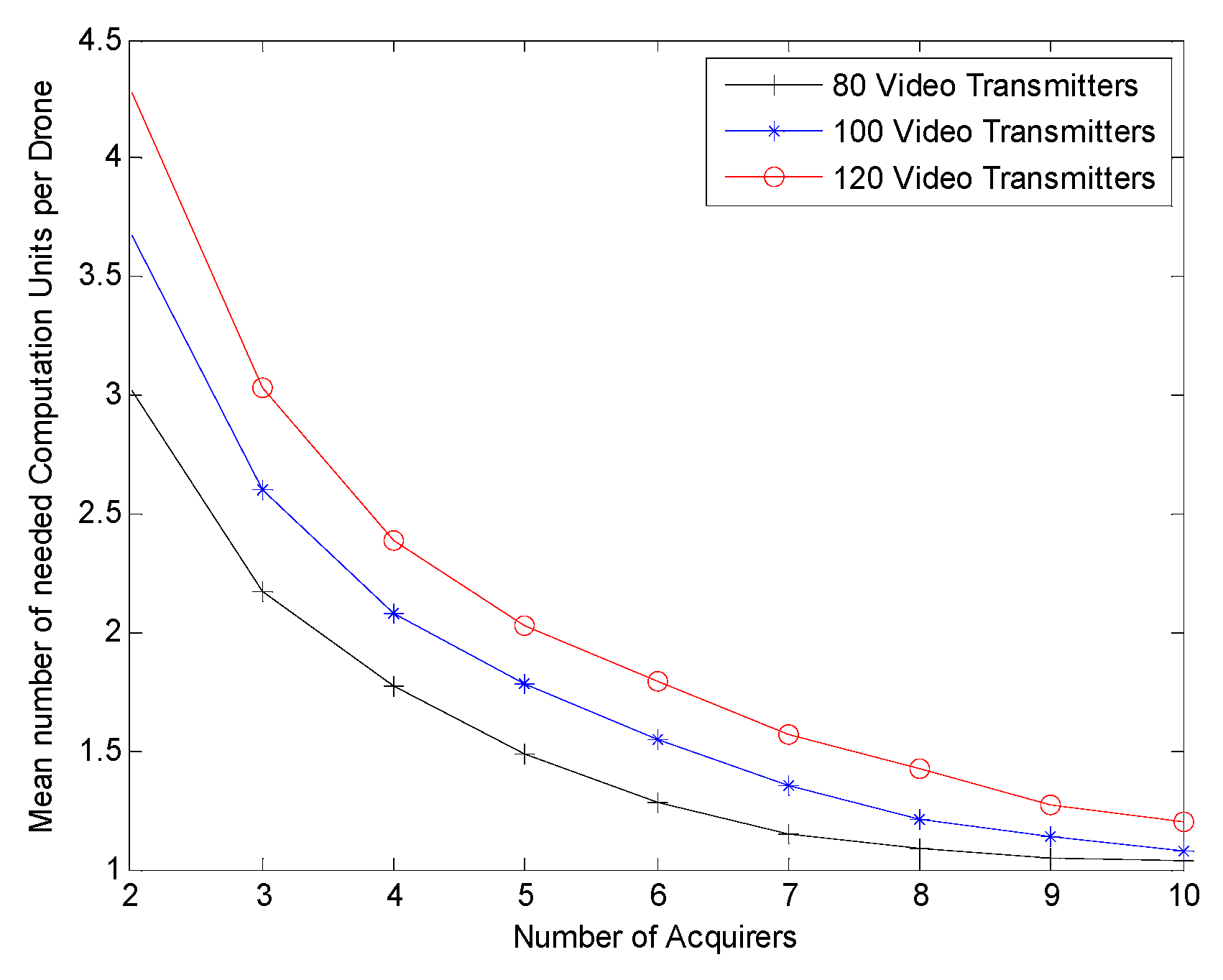
Finally, to this purpose
Figure 10 presents the mean number of active computation units needed in a single backbone drone by varying the number of acquirer nodes in the network, and for different numbers of video transmitters.


