Article

Secure and Reliable Data Exchange in Sensor Networks Utilizing Different Communication Technologies


Institute of Information and Communication Technologies, Bulgarian Academy of Sciences, Acad. G. Bonchev St. 2, 1113 Sofia, Bulgaria
Future Internet 2026, 18(7), 351; https://doi.org/10.3390/fi18070351
Submission received: 10 May 2026 / Revised: 17 June 2026 / Accepted: 2 July 2026 / Published: 4 July 2026
(This article belongs to the Special Issue Wireless Sensor Networks and Internet of Things—2nd Edition)

Abstract

The article discusses the development of a communication protocol that provides consistent security and reliability during data exchange in sensor networks. Different communication technologies are supported. The motivation for this work is presented against the background of contemporary communication technologies and capabilities. The article summarizes relevant application constraints. The capabilities of popular communication technologies are briefly analyzed. Typical sensor networks serve as examples. Work on the protocol design begins with identifying important network features that serve as requirements. The design and implementation work continues with establishing a suitable packet structure, packet processing strategies, and an overall communication flow between the nodes in the network. A concept for packet routing in large networks with different communication technologies is developed and presented. The strengths and weaknesses are summarized and discussed after testing and assessment. Future work will include enhancing protocol features to improve practical applicability in different scenarios.

Graphical Abstract

1. Introduction

Contemporary communication in sensor networks involves a variety of different technologies that constitute the path from a data source to a data sink. For example, a solar-powered sensor node in the agricultural field transmits environmental data to a local base station through a LoRa [1,2] communication link. Then, the data is uploaded to a central server through a GPRS [1] mobile data link. In industrial settings, wired solutions, e.g., RS-485 data links and Ethernet, are preferred along with proprietary radio data links, e.g., Zigbee or LoRa [1,2]. Education in STEM employs cheaper short-range radio data links based on Wi-Fi or nRF24L01+ [3]. In the automotive sector, the wired communication protocols CAN and LIN are often employed [4]. These protocols are also popular in other economic sectors, such as industrial machine control and building automation. A contributing factor is the hardware support by microcontroller units (MCUs), such as STM32 [5]. It lowers the resource threshold and simplifies the implementation.
The examples outlined above illustrate a variety of wired and wireless data communication technologies. One consequence is that any piece of data passes through multiple protocol stacks, each with different features and peculiarities. Designers and programmers have to do “data translation”. Accommodating new stack properties and restrictions leads to data repackaging and changes to the data stream. Examples include subdividing the transmitted data into frames/packets of appropriate length, adding address headers and checksums, and encoding the data bytes to include synchronization markers (e.g., COBS encoding [6]). In this context, it is difficult to implement consistent high-level features involving data security or reliability [7].
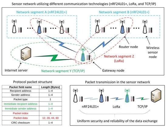
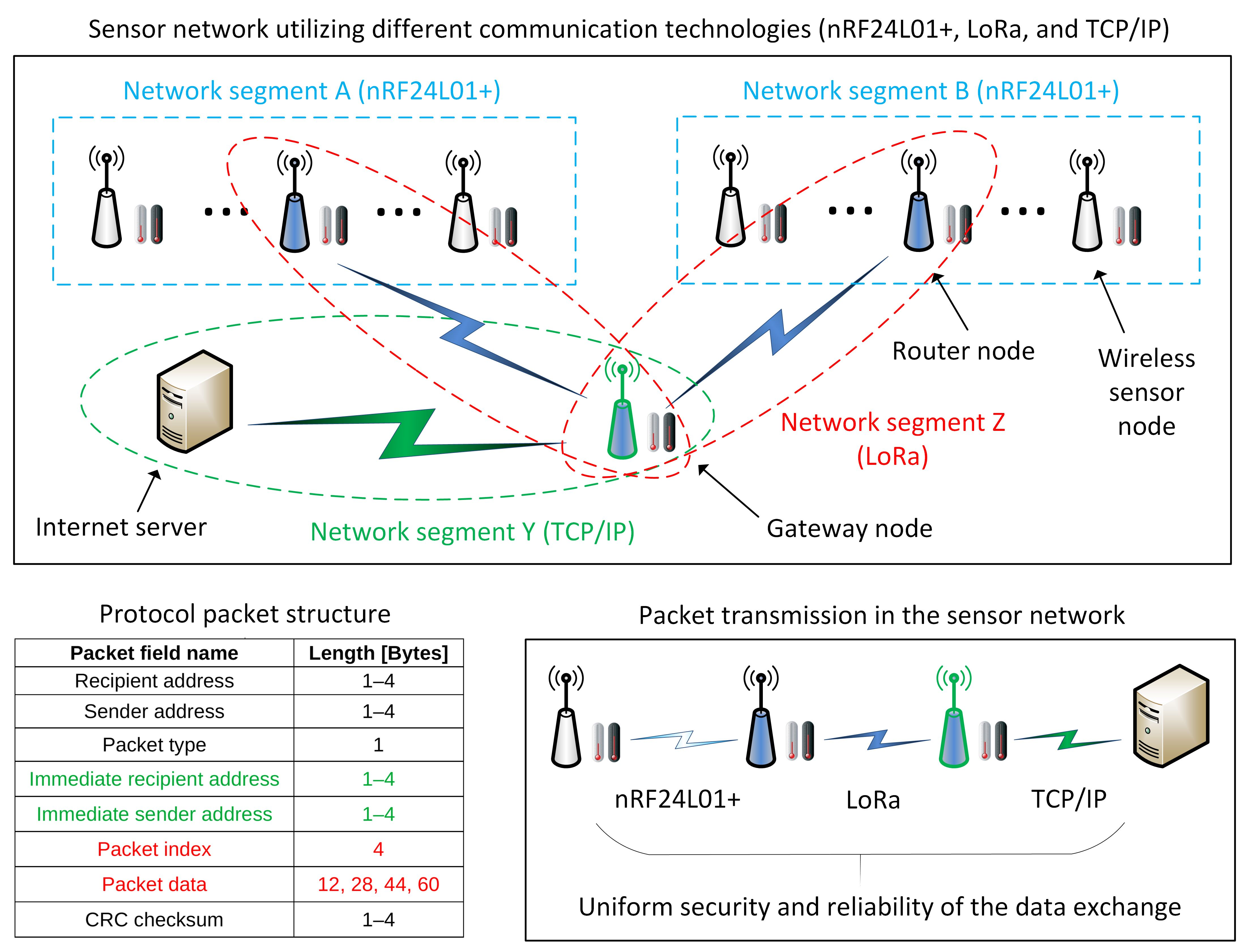
This article examines one possible solution in the form of a new communication protocol. It provides uniform security and reliability of data exchange in low-cost sensor networks that use different communication technologies. The motivation for this contribution arose after encountering the situation described above multiple times in agricultural, industrial, and educational contexts. The main advantage of the proposed protocol is that it ensures consistent data security and reliability throughout the transmission process in a unified and low-cost manner.
The main protocol features include authentication of the communication partners, data integrity checking via checksums, retransmission of lost or damaged data packets, data encryption, and optional data routing via static routing tables. One important economic benefit of this research is that the protocol serves as a ready-to-use, configurable building block during the design and creation of sensor networks. The deployment of such networks is faster, and the associated costs are lower. Network designers have some peace of mind regarding potential security and reliability issues during communication. An important downside of the communication protocol mirrors its main advantage—namely, the protocol configuration (packet size, protocol features) for the whole sensor network is determined largely by its “weakest” (least sophisticated, cheapest) data link.
The rest of the article discusses the design and development of the proposed communication protocol. The next section reviews related work on other communication protocols. Some popular communication technologies are analyzed briefly, and their main features are summarized and compared. Based on the review work, security and reliability requirements for data transmission are identified. The article discusses their integration into the communication protocol and analyzes the results. A summary of the findings and directions for future extension of the protocol concludes the discussion.

2. Materials and Methods

The next subsection presents, analyzes, and summarizes existing communication technologies and protocols from different economic fields.

2.1. Related Work

A broad review of communication technologies in the context of the Internet of Things (IoT) discusses Ethernet, Z-Wave, Zigbee, LoRa, Bluetooth, fiber optics, and others [1]. Relevant communication protocols, such as MQTT, XMPP, and AMQP, are reviewed, and important protocol characteristics are summarized. A more recent review [2] discusses wireless communication technologies, such as RFID, Bluetooth, Z-Wave, WiFi, Zigbee, and LoRa. It analyzes and compares their properties. It also reviews specific hardware suitable for implementation purposes. Another older review [8] focuses on traditional industrial automation topics, such as SCADA systems and MODBUS, and their interplay with TCP/IP, HTTP, and MQTT protocols. The conclusions emphasize the need for compatibility and interoperability as well as the importance of security. An additional review [9] discusses security and reliability in the context of IoT. The topics include data exchange protocols (e.g., MQTT and CoAP), encryption technologies (e.g., TLS and DTLS), and attack types (e.g., man-in-the-middle attacks and SSL striping). In ref. [10], the authors discuss various architectures and protocol stacks connected with IoT. They give references to the ISO/OSI model, compare protocol stacks, and categorize communication technologies (e.g., Zigbee, Bluetooth, WiFi, Z-Wave) and communication protocols (e.g., MQTT, CoAP, XMPP) according to the reference model.
Other publications focus on communication and data exchange from an application viewpoint. In ref. [11], the authors discuss the use of cellular communication, WiFi, Zigbee, Bluetooth, and other technologies in transportation and data exchange between vehicles. Building automation systems and the associated communication infrastructure are discussed in [12]. Standards such as LonWorks, BACnet, and KNX are among the topics of interest. Another review [13] focuses on smart buildings and emphasizes the role of IoT and the communication infrastructure. The review includes wireless sensor networks (WSNs) and machine-to-machine communication. They enable the online presence of everyday objects, such as appliances, doors and windows, lighting, and others. In the field of medicine, the security and traceability of communicated data are of particular importance [14]. The authors of that specific paper consider man-in-the-middle and session key disclosure attacks and propose a blockchain-based solution. In industrial settings, IoT and WSNs are a topic of lively interest. The authors of ref. [15] present a detailed review that discusses the importance of the topic. It includes associated security threats, attack types, quality of service, data privacy, data transmission, tampering, authentication, and other related issues.
In ref. [16], the authors discuss a system model related to WSNs and propose a framework for assessing WSN reliability in industrial settings. They consider various network topologies (star, linear, cluster) with and without redundancy. The use of WSNs in critical infrastructures is the topic of [17]. The authors discuss regulations and economic sectors (e.g., finance, rescue services, energies) of importance in various countries (Germany, the United Kingdom, the United States, etc.), present various standards (e.g., ISO 27001 [18], ISO 27002 [19], etc.), protocols, and communication technologies (e.g., Zigbee, NB-IoT, LoRaWAN, etc.), and introduce a categorization of WSNs by physical environment, topology, or application. The authors of ref. [20] present another interesting application. They use an underwater WSN for maritime applications and digital ship twins. The authors propose a new transmission protocol to increase the reliability and robustness of underwater data transmission. Another underground application [21] evaluates multiple wireless technologies (e.g., Sigfox, LoRa, and LTE) in underground mining.
Besides communication-related topics, sensor networks also involve other aspects of contemporary research, e.g., artificial intelligence. Machine learning algorithms are proposed to improve WSN security [22,23]. Various attack types related to WSNs (e.g., jamming, spoofing, and repudiation) and machine learning methods (e.g., convolutional neural networks) are examined and summarized. Improving energy efficiency during communication is a central topic of [24]. The authors discuss various routing protocols and present experimental results. Energy efficiency is also related to a variety of other topics. Increasing battery lifespan while powering WSN nodes is discussed in [25]. Supercapacitors can be combined with on-site energy generation via solar modules [26,27]. Energy harvesting and the possibility of a WSN to operate without batteries are discussed further in [28]. The issue of node mobility, i.e., WSN nodes that change their location arbitrarily or purposely according to an algorithm, is examined in [29]. The authors of ref. [30] discuss the optimal positions of low-power sensor nodes in a WSN coordinated with machine learning algorithms.
New wireless communication technologies and standards are developed continuously and have the potential to improve WSN capabilities. One such communication technology is LoRa, along with its associated communication protocol LoRaWAN [31]. Comparisons to competitors (e.g., Sigfox) show promise. The authors also review the network topology, protocol architecture, device classes, frequency bands, robustness, scalability, and energy efficiency. The authors of ref. [32] discuss the use of LoRa for device-to-device communication in emergencies and the integration of the technology in devices such as mobile phones. LoRa is popular in various application scenarios, e.g., smart agriculture [33,34], automotive applications [35], or industrial environments [36].
Other widespread technologies include nRF24L01+ [3,37,38] and Zigbee [39,40]. nRF24L01+ is suitable for low-cost short-range communication applications in relatively noise-free environments. Zigbee enables energy-efficient communication and supports multiple profiles and optional encryption. Cellular communication in its 2G to 5G variants is another popular technology for WSN Internet connectivity [21,41,42]. Other technologies providing Internet connectivity include Ethernet and WiFi [42,43]. Classic wired communication, e.g., RS-485, may also be used in noisy environments or when low node cost is needed [44].
In some applications, WSNs need routing capability. Popular dynamic routing protocols include RPL [45], OLSR [46,47,48], AODV [47,48], DSR [48], and others. They are used to create and update a network map in each node. This map contains communication paths to other nodes. In comparison to static routing, changes in the network topology do not require manual intervention in the ideal case. The downside is that such protocols compete for bandwidth with application message traffic and consume microcontroller resources.
Against this background, the next subsection presents the motivation for the proposed communication protocol for secure and reliable data exchange in WSNs. It discusses requirements identified facing different wired and wireless communication technologies.

2.2. Communication Protocol for Secure and Reliable Data Exchange—Motivation and Requirements

The main motivation for developing the communication protocol was to provide uniform features independent of communication technologies in low-cost WSNs (specific application scenarios are discussed in Section 4.5 and Section 4.6).
The application context usually involves transmitting small amounts of data at regular time intervals under constraints. The constraints are related to the data size, the transmission speed, the communication range, environmental conditions including electromagnetic interference, the level of security and reliability, the need for a third-party connectivity provider (e.g., a cellular data link to the Internet), bureaucratic hurdles, such as licenses, and economic expenses (e.g., cost of hardware and software components and development time). Table 1 summarizes the individual constraints related to data transmission and provides some details.
The joint evaluation of the constraints and the specific use case usually determines the choice of communication technologies for a given WSN. Based on the references from Section 2.1, a summary of popular communication technologies and their main characteristics is given in Table 2.
Communication technologies are used in conjunction with communication protocol stacks. The characteristics of some popular communication protocols and protocol stacks are compared in Table 3.
A brief analysis of Table 2 and Table 3 shows a variety of communication technologies and protocol stacks with different properties. It is important to point out that there is little cross-compatibility between technologies and protocol stacks. For example, Enhanced ShockBurst cannot be used in LoRa networks, and LoRaWAN cannot be used in conjunction with nRF24L01+ transceivers. The support for CSMA for collision avoidance or detection varies between protocols. CRC field lengths are not identical, and some protocols have no encryption support. Some communication technologies, e.g., RS-485 and RS-232, are not associated with any protocol stacks. Because of their simplicity and maturity, the price is very low, but a protocol with suitable features must be implemented.
Some protocol stacks, such as MQTT/TLS and CoAP/DTLS, operate on TCP/IP and provide encrypted data exchange and a degree of interoperability. This interoperability relies on the underlying TCP/IP protocol stack. Unfortunately, TCP/IP is the standard protocol stack only for cellular data links, WiFi, and Ethernet—relatively complex, high-speed, short-range communication technologies. These are usually not appropriate for all WSN nodes in an application scenario (besides gateways). As a side remark, some communication technologies, such as Zigbee, are also subject to possible licensing and trademark issues. For example, certification is needed if the Zigbee logo is desired.
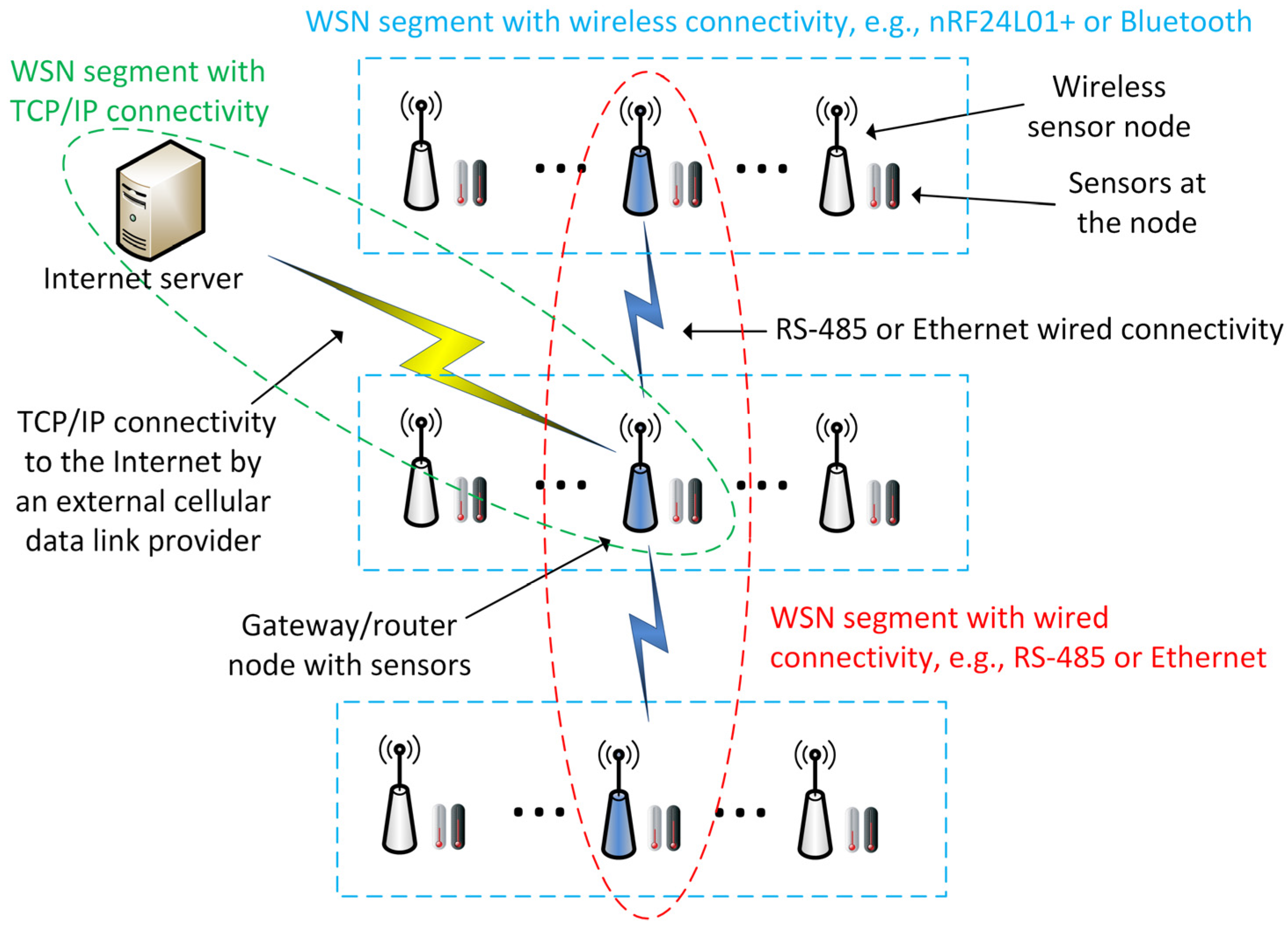
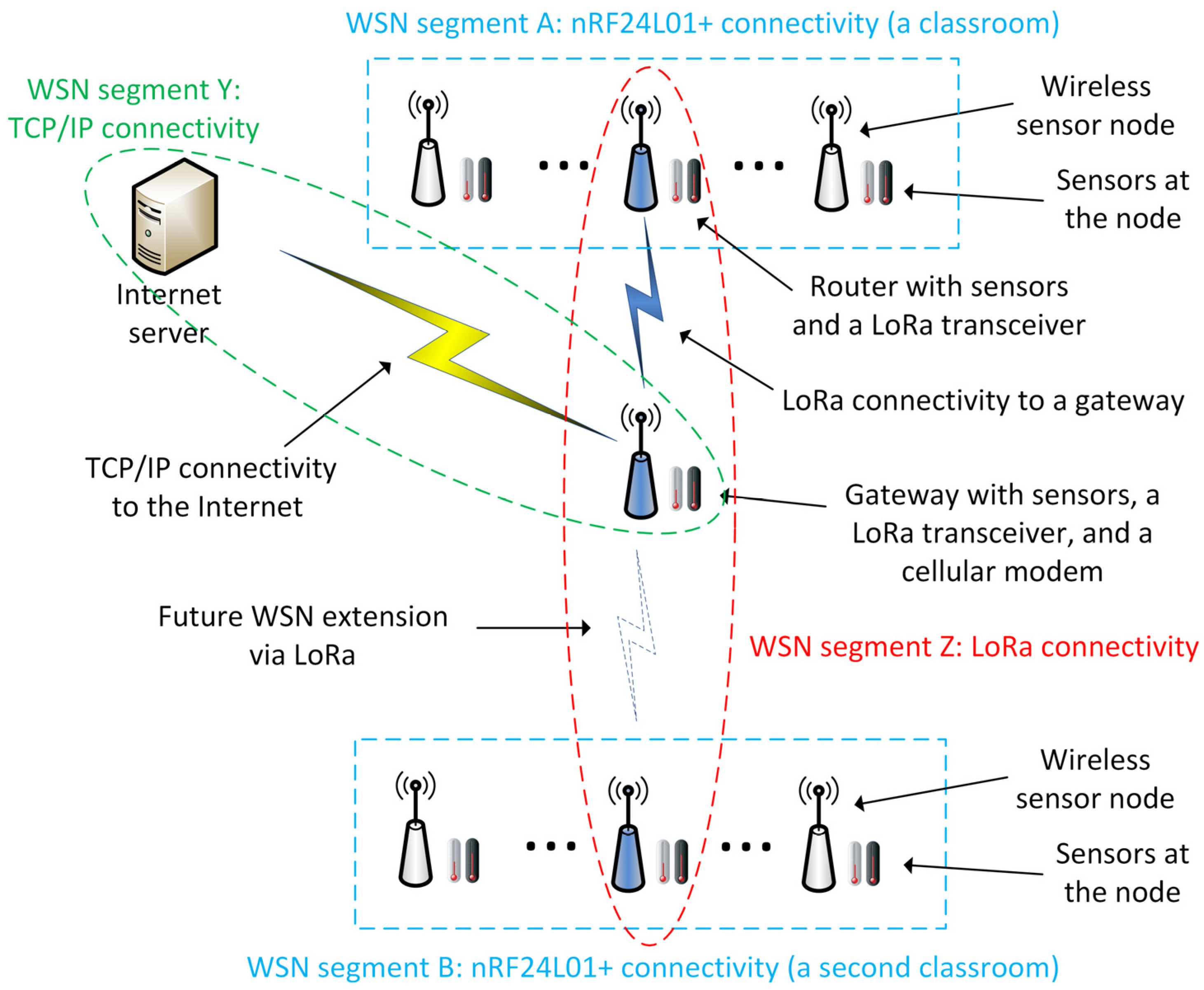
Different segments of a WSN can employ different wireless or wired communication technologies. For example, a given WSN can have an extended star topology (Figure 1). Sensor nodes are grouped into WSN segments and rely on short-range wireless connectivity, e.g., nRF24L01+ or Bluetooth. One or more nodes per segment are designated as gateway/router nodes. These nodes interconnect the individual WSN segments via RS-485 or Ethernet. These interconnections form a separate WSN segment. Another WSN segment is devoted to an external cellular data link. It is used to transmit all gathered data to an Internet server via one of the gateway/router nodes. Such a topology is useful for cost-effective sensor data gathering from multiple rooms in a building, possibly in the presence of industrial electromagnetic interference and/or existing cable infrastructure (e.g., Ethernet cabling). Even if the WSN relies on a single connectivity technology for all data links (e.g., LoRa provides a well-functioning point-to-point connectivity within a large building), connectivity to the Internet still requires a separate communication technology that supports the TCP/IP protocol stack.
The previous paragraphs, Table 2 and Table 3, and Figure 1 describe the diversity of factors, technologies, and protocols inherent in WSNs. Nevertheless, most WSN use cases require a degree of predictability and assurance. Stakeholders expect an implicit or explicit service level in the network. Achieving predictability requires careful analysis of each constraint and communication technology related to the WSN. Careful adaptation and translation of the sensor data must be performed while it travels to its destination (often on the Internet). This data adaptation and translation is a resource-intensive task during both the design and execution phases.
Dealing with WSN communication in various application scenarios and settings (e.g., commercial malls, industrial premises, school buildings, escape rooms, greenhouses, etc.) led to the appealing idea of uniform network features throughout the WSN. The main goal is to do as little data adaptation and translation as possible and to keep the network features and service level independent of the communication technology used in a given WSN segment. Most protocols listed in Table 3 (except for those based on TCP/IP) are not capable of bridging the differences between various communication technologies. A change in technology usually means replacing the communication protocol.
The main contribution of this paper is the creation of a communication protocol that can be used with multiple communication technologies. In comparison, most existing protocols can be used only with a single technology. The proposed protocol enables WSNs to choose the most appropriate technology for each network segment. Another practical benefit is that upgrading or replacing communication technologies can be done gradually without redesigning the whole WSN at once. The protocol focuses on keeping costs low and improving the security and reliability of data exchange. Security and reliability were identified as weak points in WSNs (Table 1). Other constraints are also considered during the design and development of the protocol, along with the characteristics of the communication technologies summarized in Table 2 and Table 3. The goal is to identify common ground between the different technologies. It serves as a reference point for building new features usable in WSNs that employ a combination of different communication technologies.
The motivation outlined above continues with identifying important network features that become requirements for the design of the new protocol. Among them are authentication of the communication partners, data integrity checking, retransmission of lost or damaged data packets, data encryption, and data routing (Table 4).
Authenticating communication partners in a WSN is important to avoid sensor data forging. Without it, ill-intentioned actors can introduce nodes in the WSN that disrupt its operation and falsify sensor data. Data integrity checking recognizes transmission errors and is a prerequisite for retransmitting lost or damaged data packets. The latter reduces sensor data loss, so that any control processes or data analyses benefit from time series data with as few missing values as possible. Data encryption is important for transmission privacy and for reducing the amount of information available to potential attackers. The benefit from the optional data routing depends on the specific application scenarios and communication technologies in use. If technologies with shorter communication ranges (Table 1) are used, data routing is often needed. Topologies such as an extended star are employed to create larger multi-segment WSNs (Figure 1). Technologies with longer communication ranges (e.g., LoRa) enable simpler full-mesh or star topologies and do not need additional data routing.
These network features become requirements for the proposed communication protocol. Thus, WSN users benefit from a pre-made WSN building block that delivers predictable, uniform security and reliability. Furthermore, average economic costs decrease as design and development expenditures are spread across multiple WSN projects. Individual WSNs are brought online faster with less potential for surprises.
There is one important downside to this proposition. The capabilities of the “weakest” sensor node/router/gateway and the “weakest” communication technology limit the data exchange in the WSN. “Weak” pertains to node resources (e.g., processing speed and memory), hardware support for features such as cyclic redundancy checks (CRCs), and communication technology restrictions (e.g., maximum packet size and transmission speed). In many application scenarios, sensor data packets are relatively small (usually less than 32 bytes) and do not need to be transmitted very frequently (e.g., several times per minute). That is why this shortcoming has not become a significant impediment so far. One notable exception is the insufficient hardware support for asymmetric encryption in cheap microcontroller units (MCUs), such as the low-end STM32F0 [49] or STM32G0 [50] series by STMicroelectronics, Geneva, Switzerland. If economic costs are to be kept down, asymmetric encryption is not a viable choice. In this case, symmetric encryption algorithms must implement the requirements for authentication and encryption. The resulting disadvantages and security risks are discussed in more detail in Section 4.
The next section presents the design and implementation of the communication protocol. It considers the constraints, communication technologies, network examples and features, and the requirements discussed in this section.

3. Results

This section presents design and implementation details, such as the data packet format, the node addressing scheme, and the communication flow during data exchange. Emphasis is put on the data security and reliability features.

3.1. Communication Protocol—Design and Implementation Details

The design of the communication protocol begins with an analysis of the transmission constraints and the communication technologies listed in Table 1 and Table 2, respectively. The goal is to identify peculiarities of the WSN communication and common properties of the underlying technologies or hardware that are important for the implementation stage, e.g., support for fast CRC calculation or specific encryption algorithms.
A first important peculiarity is that sensor measurement data are usually small and fit into a single packet of most packet-oriented communication technologies (e.g., nRF24L01+, Zigbee, or TCP/IP). nRF24L01+ has the smallest maximum packet size (32 bytes) while others offer more space (e.g., TCP/IP—typically around 530 bytes depending on specifics). Such technologies have a defined structure, which should be considered. Other technologies (e.g., RS-485 and LoRa without LoRaWAN) do not have a fixed default packet size. RS-485, in particular, is more similar to an open serial channel than to a packet-oriented transmission medium.
A second peculiarity concerns the added value offered by different communication technologies. While some technologies offer multiple features (e.g., WiFi uses WPA authentication and encryption), other technologies offer a clean slate (e.g., RS-485 and LoRa without LoRaWAN). In practice, the communication protocol must implement its own authentication and encryption features to ensure a uniform level of security and reliability.
A third peculiarity relates to the hardware support for specific features, such as CRC computation and encryption. Since different nodes can use different hardware, hardware-based implementations of any feature must also have an equivalent software implementation. Where supported, hardware-based implementations are used to save resources and computation time. Otherwise, the software-based implementation serves as a fallback. From an economic point of view, this mandates the use of symmetric encryption because low-cost, low-power MCUs often have insufficient resources for both asymmetric encryption and communication processing.
A fourth peculiarity is related to the communication flow. Generally, acknowledgements of received packets are needed to identify any need for retransmission. Additional hardware resources are needed to keep track of packets on both sides of the communication. Retransmissions also increase packet collisions depending on the underlying communication medium and data exchange strategy of the application scenario. From an application viewpoint, network nodes can be divided into master nodes that initiate communication and slave nodes that respond to communication requests. This strategy reduces collisions but is not appropriate for all applications. In any case, the communication protocol must consider the possibility of lost or damaged packets and handle such packets when they occur.
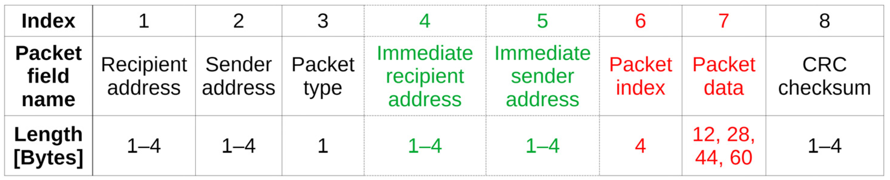
Considering the aforementioned specifics, the design of the communication protocol encompasses multiple facets. The first one is the definition of the packet structure (Figure 2).
In its extended form, the packet structure consists of a recipient address, a sender address, a packet type, an immediate recipient address, an immediate sender address, a packet index, packet data, and a CRC checksum. The recipient address contains the final destination of the packet. The sender address denotes the initial source node. The packet type contains a numerical value that specifies the packet function in the communication flow.
The two green fields containing the immediate recipient and sender addresses are optional. They are used only when routing is enabled for the WSN (see the next subsection). Otherwise, the packet structure can be shortened by 2–8 bytes depending on the node address length.
The red-colored packet index is a sequentially increasing number. A negotiated random value is used at the start of the communication between two nodes in the WSN. The value increases for each transmitted or received packet. The red-colored packet data contains the actual sensor data or command payload. The two red fields are encrypted together by a symmetric encryption algorithm, which, at the moment, is AES-256. Alternatively, some microcontrollers offer hardware support for AES-128, providing a balance between security and calculation optimizations.
The packet structure concludes with the CRC checksum of all previous fields. It is used for packet integrity verification and detection of damaged packets.
Some fields of the packet structure can vary in length depending on the specific application scenario. In small WSNs, recipient and sender addresses can be one byte long. Larger WSNs need longer addresses with a certain structure. For example, in a two-byte address field, the first byte denotes the building housing a given sensor node, and the second byte denotes a node index within the building. The packet data field is between 12 and 60 bytes. The AES algorithm operates on data blocks whose length is a multiple of 16 bytes. As the packet index is a 32-bit (4-byte) unsigned integer, optimal lengths for the packet data field are 12, 28, 44, or 60 bytes. Packet data lengths that differ from these values must be rounded up to the nearest larger value. Padding bytes must be added, causing communication overhead and wasting resources. The length of the CRC checksum varies between 1 and 4 bytes, depending on the communication technology in use and the needs of the application scenario. Large CRC checksum fields increase the reliability of packet integrity and damage checks. They have almost zero computational overhead on most 32-bit MCUs.
Some communication technologies impose additional restrictions on the packet field lengths. For example, nRF24L01+ has a maximum overall packet length of 32 bytes. It necessitates a 12-byte packet data field. If 3-byte address fields are used in a WSN with routing, this leaves 3 bytes for the CRC checksum field. Smaller WSNs that need 1-byte or 2-byte node addresses can use a 4-byte CRC checksum.
This flexibility is both a strength and a weakness of the proposed protocol. An advantage is that the protocol can be adjusted according to the application requirements. The use of communication resources, such as on-air time, can be minimized. A disadvantage is that changing the packet field lengths in any given scenario requires additional testing of the new variant. Increases in packet length can potentially worsen statistics such as retransmission rate and packet loss (see Section 4.5 and Section 4.6). Decreasing the length of the CRC field raises the probability of misidentifying damaged packets as valid. The impact of these changes on the specific WSN has to be analyzed carefully.
A second facet of the protocol design is how the individual fields of the packet structure are processed on both sides of the communication. It is intimately related to the packet structure.
The use of node address fields is relatively straightforward. When sending packets, a sending node fills the recipient address with the address of the (final) destination node and the sender address with its own node address. If routing is enabled for the WSN, the immediate recipient address changes at each hop and contains the next hop along the transmission path to the final destination. This address may or may not be the same as the recipient address, depending on the specific hop the packet is currently at. Similarly, the immediate sender address is changed at each hop to the address of the node the packet is currently at.
When receiving packets, a node filters them by the recipient address. It processes only those matching its own address. If routing is enabled for the WSN, a second processing filter is activated. It filters the packets by the immediate recipient address. If this value matches the node address, then the packet needs to be routed to the next hop along the routing path.
Packet filtering during the receiving communication phase considers the fact that some communication technologies, e.g., RS-485 or LoRa, share the communicated data (packets) among all nodes without any underlying restrictions. In this case, there is a theoretical option of encrypting the address fields in addition to the packet index and data. This option is essentially a trade-off between privacy and resource efficiency, as address decryption must be performed at all nodes for all packets, without considering the packet sender or recipient. For larger WSNs, this gets out of hand fast, and the practical choice was not to encrypt the node addresses. Other communication technologies, such as TCP/IP, encapsulate data in structures that already have their own addressing and broadcasting rules, so this issue is not relevant.
The one-byte packet type field contains information about the packet function and content. It determines the current and future activities of communication partner nodes. Possible packet types at the moment include:
  • PACKETTYPE_DATA_ACK: reception of this packet must be acknowledged by sending a new data packet of type PACKETTYPE_DATA_ACK or PACKETTYPE_DATA_NOACK back to the sender node within a predefined time interval.
  • PACKETTYPE_DATA_NOACK: reception of this packet must not be acknowledged.
  • PACKETTYPE_INDEX_REQ1 to PACKETTYPE_INDEX_REQ8: this packet contains a new connection request (see Algorithm 1, Algorithm 2 and Algorithm 3).
  • PACKETTYPE_INDEX_RESP1 to PACKETTYPE_INDEX_RESP8: this packet contains a connection response after a received connection request (see Algorithm 1, Algorithm 2 and Algorithm 3);
  • PACKETTYPE_INDEX_ERR: this packet invalidates an existing packet index/connection.
  • Others that will be implemented in the future (e.g., immediate packet acknowledgement with no data).
The packet index field has two important tasks during communication. First, it serves to negotiate and maintain a connection between two communicating nodes. Second, it provides means to track received/expected packets (depending on the point of view) and detect packet losses. An important consideration during protocol design was whether to maintain a communication state. The state needs memory resources at each node, but it is essential for packet loss detection. Currently, a table maintained at each node contains four values per communication partner (Table 5).
The node address field contains the address of a communication partner with which an active connection has been established. The packet index field is the currently negotiated packet index value for that communication partner. The one-byte request ID field is used to filter out lost or damaged packets during the connection negotiation. The use of this field is currently suboptimal. One future optimization is to merge it with the connection state field to optimize the RAM usage. Still, it occupies only one byte per connection, so this is not critical. In addition, there is potential to extend its use in the future to support and track multiple connections per communication partner. The connection state field indicates whether the current node expects a PACKETTYPE_INDEX_RESP1 to PACKETTYPE_INDEX_RESP8 or an acknowledgement data packet as the next received packet from the communication partner. Its values are adjusted when the current node sends a packet of type PACKETTYPE_INDEX_REQ1 to PACKETTYPE_INDEX_REQ8 or PACKETTYPE_DATA_ACK. In the future, it will be modified to indicate connection validity, which will be more convenient than the current approach of invalidating the packet index field.
A communication partner can be any node with which the current node is allowed to communicate. Optional address whitelists and blacklists will be used in the future to filter out communication packets from undesirable communication partners and establish explicit communication restrictions within the network.
The memory needed by the communication state table depends on the node address length and degree. For a full-mesh network, this amount increases quickly, but it is still between 7 and 10 bytes per node. Moreover, most practical networks implemented so far that use the protocol employ a simple or extended star topology. Most nodes communicate only with a single router or gateway. Routers and gateways must keep track of connections to multiple network nodes. They can employ more powerful MCUs with more RAM to house the communication state table. Still, for a simple star WSN of 100 nodes, the necessary RAM for the communication state in a gateway is below 700 and 1000 bytes, which is feasible even for low-cost MCUs. The table can be implemented as a static or dynamic structure. The approach chosen at the moment is to implement it as a static array of a predefined length. The length depends on the WSN size and topology. The array elements (corresponding to the rows in Table 5) fill dynamically with data about communication partners, and newer communications replace older ones if the array size is insufficient to track communication with all partners.
The packet data field is not processed by the protocol other than encrypting or decrypting it together with the packet index field before sending or after receiving a packet. The data field values are obtained from or passed to the application code, respectively. The symmetric encryption algorithm—currently AES-256—employs a password that is shared among the communication partners. When receiving packets that require acknowledgement (PACKETTYPE_DATA_ACK), care must be taken that the application code does not delay the acknowledgement response for too long. An option for immediate packet acknowledgement before any application code processing takes place is planned for the near future, but this wastes resources when the acknowledgement can be sent together with actual packet data values that the application code fills in.
The CRC checksum is calculated for each packet that is sent or received. It is written to or compared with the value in the CRC checksum field, respectively. When receiving a packet, if the calculated CRC value differs from the value in the CRC checksum field, the packet is regarded as damaged and discarded.
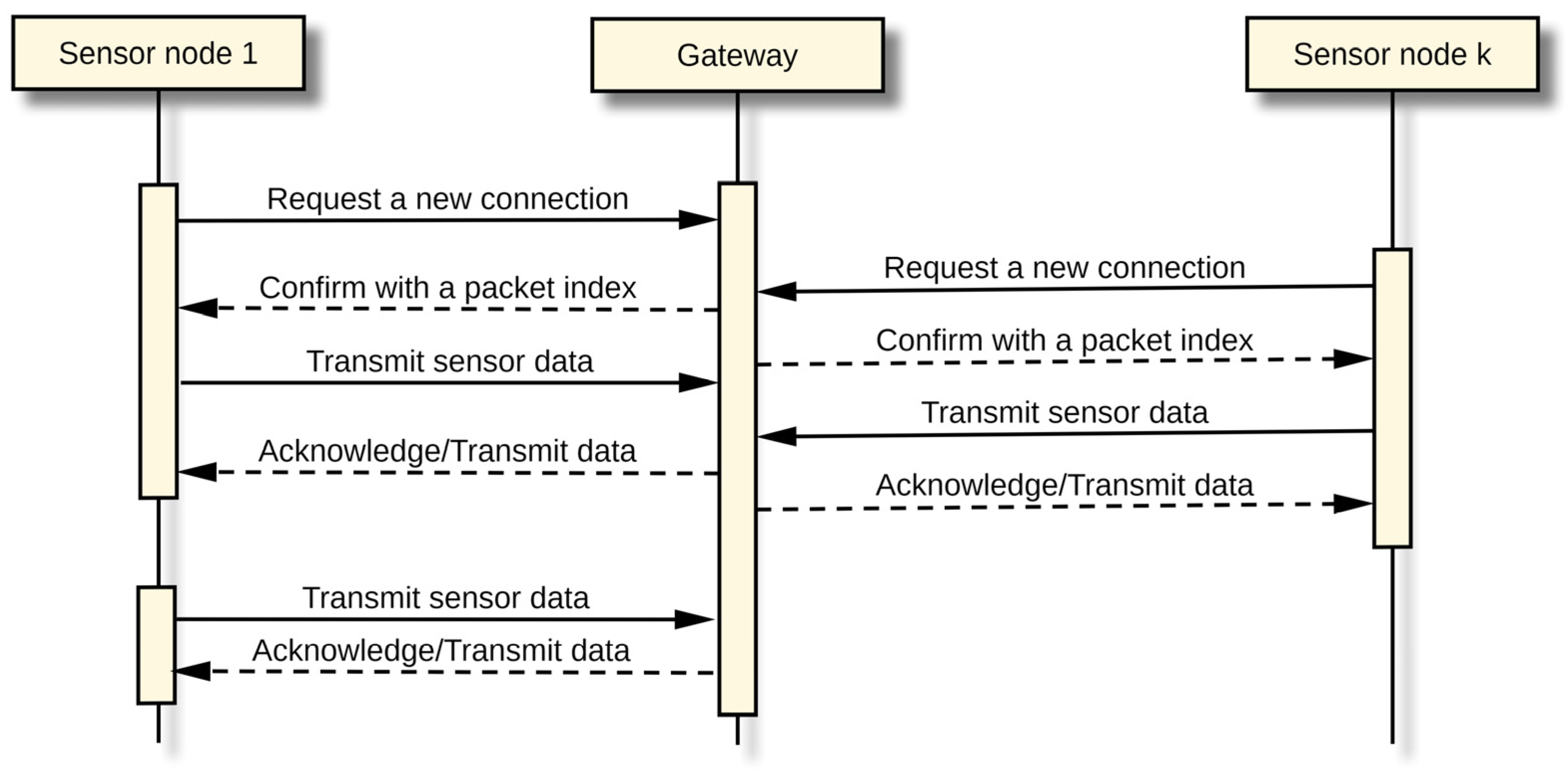
A third facet of the protocol design relates to the overall packet communication flow between communication partners (Figure 3). The sequence diagram illustrates a WSN with multiple sensor nodes that send sensor data at regular intervals to a predefined gateway node. Depending on application needs, other communication strategies are also possible, e.g., a gateway that polls the sensor nodes for data.
The communication flow encompasses two general phases: negotiating a new connection and data transmission. Algorithm 1, Algorithm 2 and Algorithm 3 contain the steps performed when a sender node negotiates a new connection with a recipient node.
Algorithm 1. Requesting a new connection (sender node)
Step 1. Set the packet index to an initial fixed value (may depend on the communication partner).
Step 2. Fill the first four bytes of the packet data field with an expected packet index value.
Step 3. Set the packet type to a request ID value between PACKETTYPE_INDEX_REQ1 and PACKETTYPE_INDEX_REQ8.
Step 4. Save the partner address, the request ID, and the expected packet index in the connection state table (Table 5).
Step 5. Send the connection request packet.
Algorithm 2. Receiving a new connection request packet (recipient node)
Step 1. Compare the received packet index value with the initial fixed value.
Step 1a. If it does not match, invalidate the connection with the partner node.
Step 1b. If it matches, create a response packet.
Step 2. Set the packet index to the expected packet index value received in the packet data field of the request.
Step 3. Fill the first four bytes of the packet data field with a newly generated connection packet index.
Step 4. Set the response packet type to the PACKETTYPE_INDEX_RESPX value that matches the request ID encoded in the PACKETTYPE_INDEX_REQX.
Step 5. Save the partner address, the request ID, and the newly generated connection packet index in the connection state table (Table 5)
Step 6. Send the connection response packet.
Algorithm 3. Receiving a connection response packet (sender node)
Step 1. Compare the received packet index value with the expected packet index in the connection state table (Table 5).
Step 1a. If it does not match, invalidate the connection with the partner node.
Step 1b. If it matches, replace the packet index in the connection state table (Table 5) with the connection packet index received in the response packet data field.
After the connection has been negotiated, a valid and identical packet index value is present in the connection state tables of both communication partners. Each transmission or reception event for a new packet on both sides increases the packet index by one. Such events include sensor data transmitted from a sensor node to the gateway and acknowledgements and/or data transmitted from the gateway back to the sensor nodes. When a packet is received, its packet index (PI) is compared with the packet index stored in the connection state table (PI_CST). Several cases are possible:
  • PI = PI_CST: a new, valid packet. It is processed accordingly.
  • PI = PI_CST − 1: a duplicated or retransmitted data packet that has not been acknowledged yet. It is ignored.
  • PI = PI_CST − 2: an acknowledgement has been lost. A retransmission of the last packet is attempted without changing the packet index value.
  • PI > PI_CST or PI < PI_CST − 2: invalid packet index. Packet loss has accumulated, the encryption password differs, or the communication partner has been reset. The connection is invalidated. A PACKETTYPE_INDEX_ERR packet may be sent back.
Damaged packets with invalid CRC checksums are ignored. If the sender has sent a PACKETTYPE_DATA_ACK packet and does not receive an acknowledgement within the predefined time interval, it will attempt to retransmit the packet sent to the recipient without changing the packet index value. While the packet index values stored in the connection state tables of both communication partners are identical or nearly equal (see Table 5 and the previous paragraphs), the connection is considered valid, and it does not need to be renegotiated before sending a new packet.
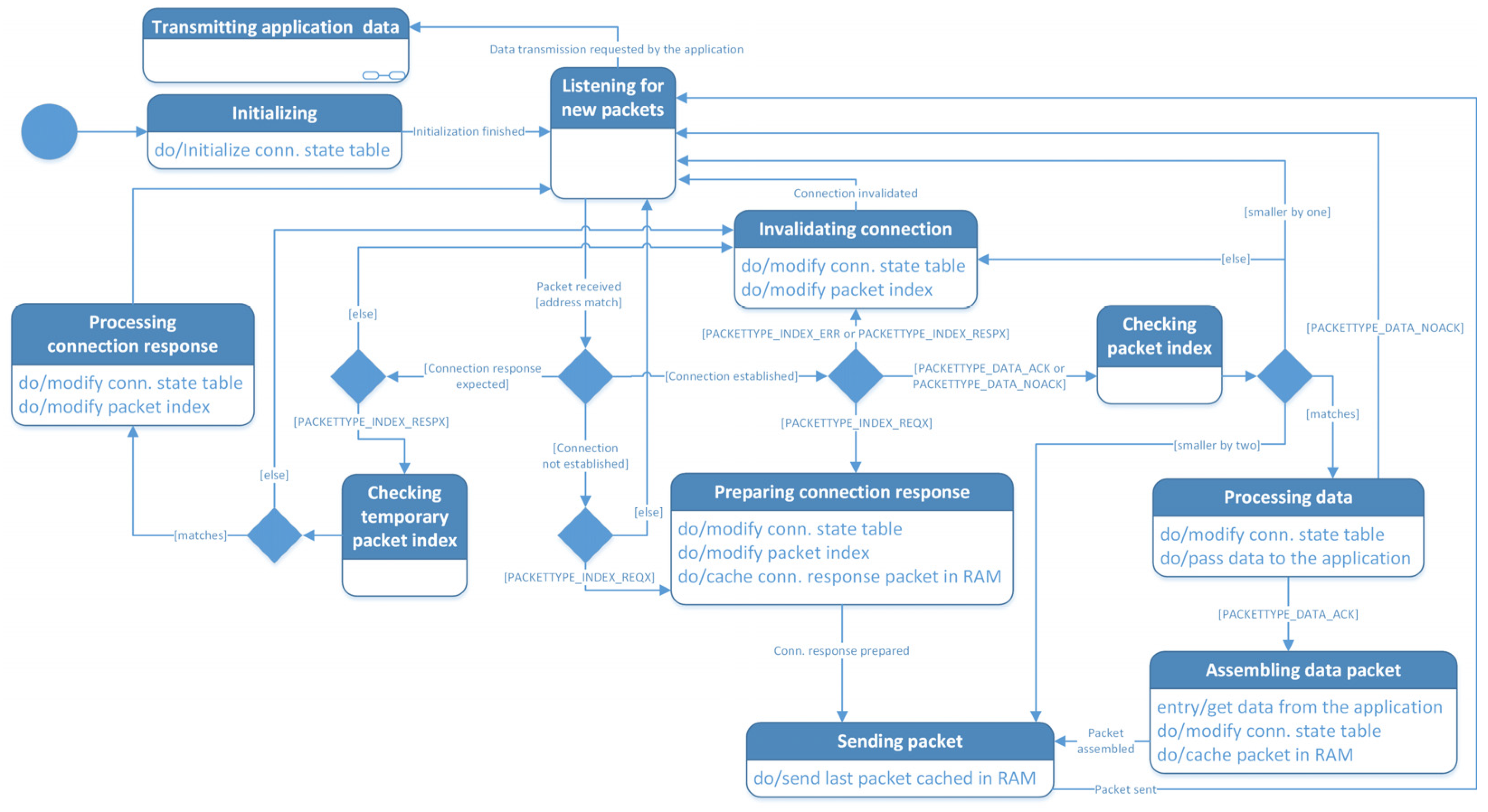
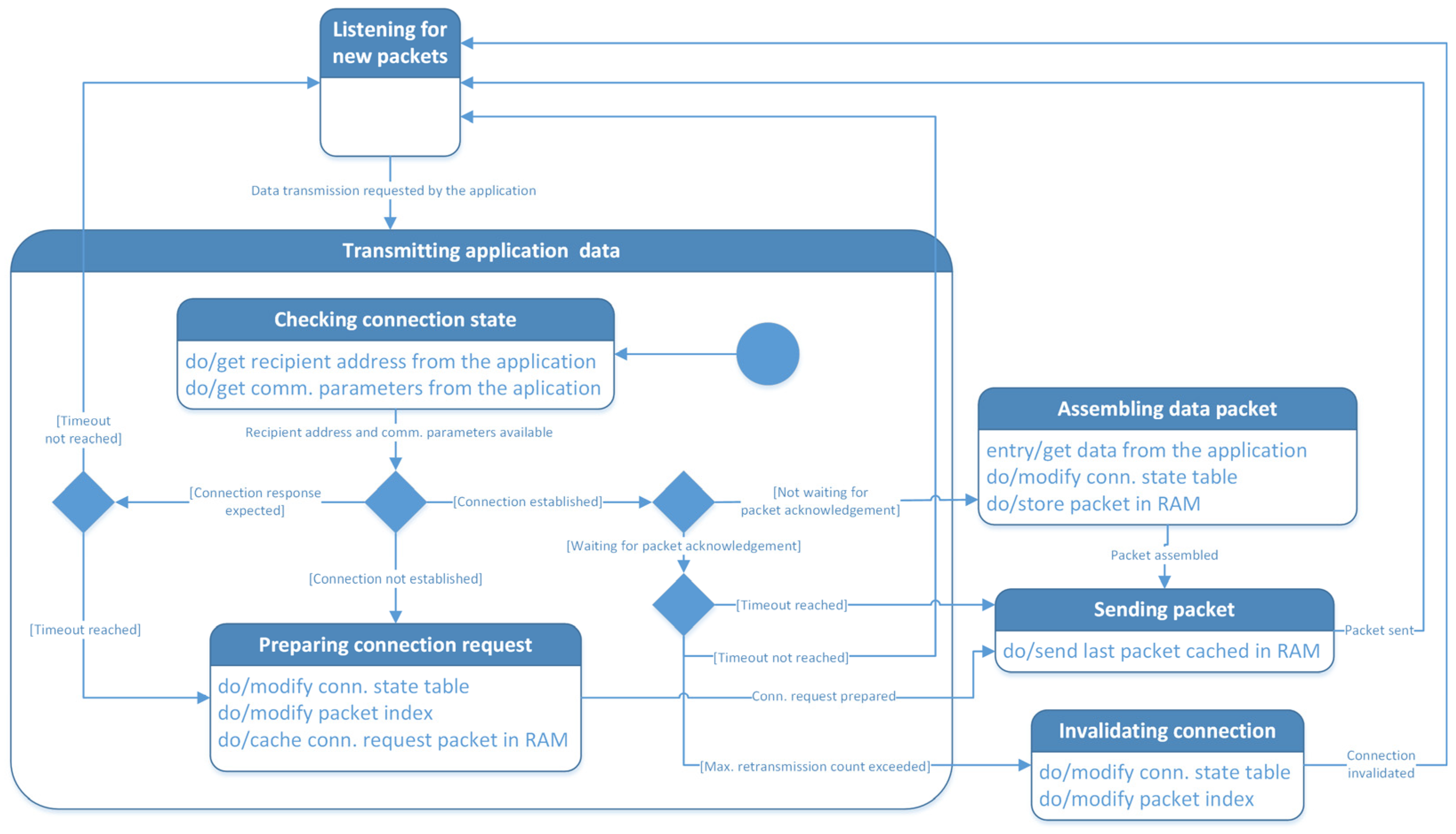
Figure 4 and Figure 5 complement the textual description of the previous paragraphs. They model the processes of packet reception and transmission, respectively, by using state machine diagrams.
The “Listening for new packets” is the default state if the node is initialized and awake. After address matching, received packets are processed according to packet type and the connection state table. Before sending, the packets are cached in the MCU RAM, and if a retransmission is needed, they are taken directly from the cache without needing a reassembly.
When sending packets that require acknowledgement, the application sets a retransmission timeout value and a maximum retransmission count. If the maximum retransmission count is exceeded, the current approach is to invalidate the connection. An alternative is to let the connection exist and invalidate it only when a PACKETTYPE_INDEX_ERR is received from the communication partner.
At the moment, the protocol assumes that there is at most one connection per communication partner. In the future, the request ID field in the connection state table (Table 5) and the connection request/response ID values in the packet type field will also be used in the data transmission phase. In this way, the protocol will keep track of multiple connections between two communication partners.

3.2. Extended Star Network Topology and Packet Routing

As mentioned in the previous section, most applications encountered so far use either a simple or an extended star network topology. Simple star topology is often sufficient for smaller networks, especially when coupled with a communication technology such as LoRa. For larger networks or communication technologies with a shorter range, such as nRF24L01+, the simple star topology evolves into an extended star (see the example in Figure 1). It is done by adding new communication nodes or designating already existing ones as routers. Routers process packets not intended for them and forward these packets hop-by-hop from the initial sender to the final destination.
The approach is similar to the previous subsection. When a sending or forwarding node constructs or forwards a packet, it fills in the immediate sender address field (see Figure 2) with its own node address and the immediate recipient address with the address of the router node designated as the next hop. Then, a connection between the intermediary sender and intermediary recipient nodes is established as described in the previous section, and the packet is sent to the intermediary recipient. During connection processing, the intermediary recipient and intermediary sender address fields are used to handle the communication flow in place of the recipient and sender address fields.
The next hop depends on the data in the recipient address field (Figure 2) and brings the packet closer to the final destination node. The proposed solution involves the usage of a static routing table (Table 6).
Starting from the first table row and proceeding downwards, the recipient address of each incoming packet is masked by the value in the address mask field. The result (the first sixteen bits of the recipient address in this example) is compared to the value of the address pool field. If they match, the “next hop” field value is used as the immediate recipient address for the packet. If multiple communication technologies are available at the current node, the interface index field specifies which communication technology is used to forward the packet. The last table row may contain address pool and mask values matching any recipient address. It designates the default next hop. If such a row does not exist and no table row matches, the immediate recipient address is set to the recipient address, i.e., the current node is assumed to access the recipient directly. In the future, the routing table will be extended to include this information explicitly for easier troubleshooting of larger networks.
The “next hop” address does not always relate directly to the address pool of the same row. It depends on the network topology, the need for multi-hop routing, the node address configuration within the network, and the communication technologies. The routing table also assumes that WSN addresses consist of a network part (e.g., the first two address bytes) and a host part (e.g., the last address byte), which is convenient but not obligatory.
The static routing approach is economical due to the relatively little overhead for nodes to determine the next hop for a given packet. The proposed routing scheme is still experimental, but preliminary tests show that it works as intended. For some communication technologies, such as LoRa, the transmission speed is relatively low, but with sufficient communication time, routing is successful.
The downside to static routing is the need for careful planning when the network topology is created or altered. The routing configuration must be reexamined when node locations, count, or roles change and when nodes are replaced due to failure or accidents. The increase in WSN size or complexity contributes to scalability and management issues. Misconfigured nodes are difficult to trace, and corrections require on-site visits and taking the respective nodes offline for reprogramming.
An alternative is to use dynamic routing protocols such as RPL, OLSR, AODV, or DSR. They consume additional bandwidth and energy, but handle routing table reconfigurations. Table 7 summarizes some important characteristics of these routing protocols. RPL and OLSR are proactive protocols that send messages at regular time intervals. AODV and DSR are reactive protocols that send messages only when needed. The message size of DSR depends on the address and path lengths in the WSN, i.e., larger networks use larger message sizes. While routing protocols can be adapted to different communication technologies, they are easiest to use with the technologies that were the initial focus of their development. For all routing protocols, the communication technology must support broadcast messages.
One potential problem when adapting dynamic routing protocols for use with the proposed communication protocol is the data size restriction. For some WSNs, routing messages must be segmented into two or more packets. Low-cost technologies such as nRF24L01+ are heavily impacted, while more sophisticated technologies and protocols such as Zigbee and TCP/IP fare better. Any future implementation of dynamic routing must be compatible with the communication technologies supported by the proposed protocol to preserve its main advantages. Future work will examine this topic in more detail.
The proposed static routing approach has one additional weakness. Each router must decrypt and re-encrypt the packet index and data of each forwarded packet to prepare the packet index for the next hop. Since the encryption password is shared among all nodes, this is doable but needs the respective resources.

4. Discussion

The proposed communication protocol focuses on application scenarios that need different communication technologies and a uniform level of security and reliability during the data exchange. It has been tested with LoRa, nRF24L01+, RS-485, CAN (hardware support is present in some STM32 MCUs), and cellular TCP/IP-based data links. WiFi and Ethernet tests are pending, but they are not expected to pose problems considering the experience with cellular data links. The security of the transmitted data is achieved (in the usual case) by using AES-256 symmetric encryption and connection negotiation. The reliability of data transmission is supported by CRC checksums and retransmission of lost or damaged packets. This executive summary of the proposed protocol already gives hints about the inherent strengths and weaknesses of the approach.
An important point is that economic factors, such as the need for low cost, limit the effectiveness. Customers in agricultural, industrial, and educational contexts who invest in technological solutions consider the price of the intended solution and the cost of maintenance and upgrades. These considerations are paramount and often outweigh the presence or absence of technical features. From a development point of view, low cost requires the protocol to be compatible with different network technologies. It must also run on “weak” MCUs, such as Cortex-M0. This flexibility makes it possible to upgrade existing WSN protocols without costly hardware replacements. The downside is that low-cost MCUs have their technical limitations. Assessments and findings from our tests are presented in the next subsections.

4.1. Protocol Strengths

One main strength of the protocol lies in its low overhead, which translates directly to low hardware cost. Existing WSNs built with low-cost nodes can switch to the new protocol without needing an MCU upgrade at every node—especially if the nodes already have MCUs with a 32-bit architecture, such as ARM Cortex-M0/M0+. As recent trends emphasize the use of 32-bit MCUs, the proposed protocol can, in some cases, upgrade network security and reliability without additional hardware costs. Key decisions that contribute to this include:
  • Using symmetric instead of asymmetric encryption;
  • Using a 32-byte packet format in the usual case;
  • Explicit support for small WSNs with less than 256 nodes (one-byte address fields);
  • Hardware support for CRC checksum calculations (STM32 MCUs);
  • Using a static routing table to save MCU resources and bandwidth in extended star network topologies.
Another protocol strength is the ability to change or combine underlying communication technologies, while keeping the protocol features intact and development costs down. For example, a group of wireless sensor nodes forms a WSN segment. This segment is connected via an RS-485 or CAN line to a remote gateway/router node. The gateway/router receives the sensor data from the WSN and forwards it to the Internet via a cellular data link. Other situations can combine low-cost nRF24L01+ transceivers for short-range communication within a room with moderately priced LoRa transceivers that forward the information to a central building on a campus. In any case, the ability to choose from and combine multiple communication technologies makes the network design more flexible and easier to optimize for a given application scenario, e.g.:
  • Some applications require low cost.
  • Industrial applications benefit from sub-1 GHz transceivers or wired connectivity.
  • Applications involving WSN upgrades need to reuse node groups with already established connectivity options.
The protocol strengths emphasize the importance of economic factors for customers’ choice of technical solutions. The protocol efficiency and flexibility translate directly into low hardware costs and opportunities to extend or upgrade WSNs with new communication technologies. Unfortunately, economic factors lead to weaknesses on the technical side that serve as important counterpoints.

4.2. Protocol Weaknesses

The next subsections discuss two protocol weaknesses from a technical perspective.

4.2.1. Symmetric Encryption

One major weakness is the full reliance on symmetric encryption algorithms. Asymmetric encryption is not used due to resource and performance limitations resulting from economic factors. Table 8 illustrates the situation and the reasons behind this decision. It includes several encryption algorithm variants and shows benchmark results and resource consumption values on different MCUs for a 16-byte payload. The first number in the benchmark columns denotes the cycles needed for encoding (AES) or public key operations (RSA-2048). The second number denotes the cycles needed for decoding (AES) or private key operations (RSA-2048). Optimization means that assembly routines are used to improve the benchmarks and the resource consumption, but the code cannot be compiled directly for other MCUs or desktop machines.
A comparison of the benchmarks shows that AES-128 and AES-256, both with and without assembly optimization, can run without major impediments on low-cost Cortex-M0 MCUs (e.g., STM32F0). These MCUs typically have a clock speed of 48 MHz, 16–64 KB flash memory, and 4–16 KB RAM. At this processing speed, all AES implementations need significantly less than 1 ms to encode or decode packet contents. The code size is relatively small compared to the available flash memory, and the RAM requirements of 1 KB or less are tolerable. The table shows that Cortex-M3 and M4 MCUs are more powerful and require fewer cycles. Unfortunately, they also have a significantly higher price point.
Table 8 also shows RSA-2048 benchmarks performed by a Cortex-M4 MCU (see [51]). The difference in performance and RAM consumption is clearly visible. About 257 thousand cycles are needed for public key operations, and 10.8 million cycles are needed for private key operations with assembly optimization. Compared to a Cortex-M4, a low-cost Cortex-M0 MCU lacks a hardware divide unit, so its results would be significantly worse. Apart from the substantially larger number of cycles, the significant RAM consumption represents another big hindrance. Most low-cost MCUs do not have sufficient RAM to support sensor data acquisition, the communication protocol overhead, and the RSA encryption/decryption.
As a result, symmetric encryption algorithms remain the only viable choice under the premise of low cost. Assembly optimization has performance advantages and requires fewer resources, but at this stage, the flexibility of an implementation without assembly routines is preferred. It uses the same implementation on different MCUs and desktop/server machines, ensuring that all participants in the data exchange (see Figure 1) use identical encryption protocol routines. Comparing the performance of the unoptimized versions of AES-128 and AES-256, the benchmarks show that AES-128 speeds up calculations, but not significantly. Due to this reason, the algorithm of choice is AES-256 without assembly optimization.
The choice of communication technology is the most important factor that influences communication speed. Still, the nodes’ processing speed is important, especially for routers and gateways, which are focal points for communication packets. The most time-consuming tasks are encryption and decryption. Table 8 provides indications about the expected performance for several types of Cortex-M MCUs. One factor not visible from the table is that a typical Cortex-M4 MCU runs at about 84–168 MHz—several times faster than a Cortex-M0. Even without optimization, bottlenecks related to processing speed were not observed, especially when compared to speed issues arising from the communication technologies.

4.2.2. Communication Technology Influence

The reliability of the transmission still depends, to a certain extent, on the physical characteristics of the underlying communication technology. For example, in urban or industrial environments, most 2.4 GHz technologies are more susceptible to noise than sub-1 GHz technologies. Noise lowers the maximum transmission range, increases packet loss, and decreases the overall transmission speed. When multiple communication technologies are combined, the transmission speed is usually limited by the slowest link on the path between a sensor node and the gateway. For example, even if nRF24L01+ transceivers gather sensor data quickly, the packets must be delayed when transmitted further over a slower LoRa link.

4.3. Security Validation

The security validation of the proposed protocol examines three important aspects: authentication, confidentiality, and integrity. They depend heavily on the type of encryption and the encryption algorithm chosen for the packet index and data. As discussed in Section 4.2.1, the protocol uses symmetric encryption and AES-256.
From a mathematical viewpoint, AES-256 does not have a formal security proof. Instead, it is regarded as “computationally secure” in the sense that current computing machines lack sufficient resources and time to break the algorithm. Due to its strong dependence on AES-256, the proposed protocol does not have a formal security proof, either.
With the advent of quantum computing, things may change for both symmetric and asymmetric encryption. Future developments will take note of technological progress in this area.

4.3.1. Authentication

Authentication involves the partner node identity verification. The protocol uses the packet index and the sender address for this purpose.
The correctness of the packet index depends on the knowledge of the shared network password. Only data from packets with a correct index are accepted (Figure 4). Consequently, a node is considered authenticated if it knows the shared password.
The actual identity verification is done via the “sender address” field. It is not encrypted, and the partner node sets it according to its configuration. The recipient does not validate its truthfulness and has only limited means to perform checks. The protocol considers authenticated nodes legitimate and cooperative. They set their sender address truthfully and obey the protocol convention.
This discussion emphasizes the importance of the shared password and the susceptibility of the protocol if a legitimate node is compromised and turned adversarial.

4.3.2. Confidentiality

Confidentiality refers to keeping data transmitted between network nodes private. The argumentation from the previous subsection is valid. Nodes that know the shared password can decrypt the data from the entire WSN. The routing function also utilizes this capability.
Without the password, attackers have access only to the encrypted combination of packet index and data. The contents remain protected. The packet index changes dynamically, so identical data does not have an identical encrypted representation.
As in the previous subsection, the protocol is vulnerable if a legitimate network node, especially a router, is compromised. In this case, all network traffic is exposed.

4.3.3. Integrity

Integrity refers to keeping the data unchanged during transmission from the sender to the recipient. Any unauthorized changes must be detectable. Data integrity depends on two factors—the checksum and the shared password.
The checksum is generated by the sender and checked by the recipient. It protects the data against accidental packet damage. The protection level is directly proportional to the length of the checksum field (Figure 2). The experimental work in Section 4.5 and Section 4.6 employs 3-byte checksums.
The shared password protects the data against malicious changes by unauthorized nodes. Any node wishing to transmit or receive data must use the shared password to encrypt or decrypt it together with the packet index. The packet index changes with each transmission, making simple retransmissions without re-encryption ineffective (see Section 4.4.1).
As in the previous subsections, if a legitimate network node, especially a router, is compromised, it can easily falsify data.

4.4. Adversarial Assessment

As part of the adversarial assessment, the communication protocol capabilities to protect data transmissions, detect unauthorized activity, react to security threats, and restore normal network operation are examined. Sniffing attacks, replay attacks, node spoofing, man-in-the-middle (MITM) attacks, node capture, denial-of-service (DoS), and social engineering are analyzed.
Sniffing attacks refer to intercepting and recording legitimate packet transmissions for later analysis. Replay attacks involve attackers recording transmitted packets and resending them to trick legitimate network nodes. Node spoofing forges a legitimate node’s identity. Attackers often use it to perform MITM attacks, i.e., a rogue node is introduced in the WSN to record transmitted data and/or control or disrupt the data flow through the network. Node capture involves obtaining physical or remote access to a legitimate network node and extracting confidential information, such as passwords and cryptographic keys. DoS attacks disrupt the network by flooding nodes with communication requests. They occupy resources and slow down or completely stop legitimate traffic. Social engineering refers to using people’s actions to compromise security. In the context of the proposed protocol, this involves tricking WSN administrators to reveal node configurations (e.g., shared passwords, node and gateway addresses, and static routing tables).
At this stage, it must be emphasized that one common weakness of the proposed protocol is its reliance on symmetric encryption without using asymmetric keys. Connection negotiation and data transmission rely on a password shared among all WSN nodes. If an attacker learns the shared password and has a blueprint of the protocol, he will gain full access to the WSN. In the next subsections, attackers are assumed to have full knowledge of the communication protocol.

4.4.1. Data Transmission Protection

Data transmission protection includes the protocol capability to transmit data without unauthorized third parties capturing the contents or disrupting the communication. Capturing encrypted contents via sniffing is generally possible for attackers if they have access to the underlying communication medium via suitable hardware transceivers. Decrypting the contents requires access to the shared password. In this sense, the contents are protected as long as the password remains secure. Alternative means for content capture, such as electromagnetic analysis, also remain a theoretical possibility.
With access to the communication medium (e.g., in cases of wireless transmissions), attackers can also disrupt communication. One possibility is that an attacker does a combination of node spoofing and denial-of-service attacks. Since node addresses are not encrypted, an attacker is assumed to know at least some legitimate node addresses. They can be used to forge a connection request. A rogue node equipped with the corresponding transmission technology first listens to existing traffic and records legitimate sender/recipient address pairs. Then, it sends a communication request packet (PACKETTYPE_INDEX_REQ1 to PACKETTYPE_INDEX_REQ8 packet index) using one of the captured pairs. It performs partial node spoofing, which is sufficient to reset the connection for the two legitimate nodes and cause new connection negotiation at a later point in time. If this approach is used to perform a denial-of-service attack, i.e., enough rogue communication requests are sent, communication through the network will be disrupted, especially if router or gateway nodes are attacked. Full node spoofing, i.e., successful connection negotiation, between a rogue node and a legitimate node requires the shared password to synchronize the packet index successfully.
Another type of denial-of-service attack involves a rogue node listening to the communication and responding to communication requests or PACKETTYPE_DATA_ACK packets in the name of legitimate nodes. This action causes collisions and frequent invalidations.
Replay attacks lead to packet retransmissions or connection invalidations. As the encrypted packet index does not change, nodes do not regard replayed packets as new data and do not process their contents. Depending on the delay of the replay, the packet is ignored, a previously sent acknowledgement is retransmitted, or the connection is invalidated. Essentially, the protocol handles replay attacks as an increase in packet loss. Delayed packets and packet index desynchronization can occur naturally or as a result of an attack. The receiving nodes handle these situations in the same way as replay attacks. Packet contents are not processed until synchronization is restored or the connection is invalidated. Pure MITM attacks have little potential to disrupt communication flow due to the shared communication medium and the static nature of routing in larger WSNs.
Node capture is associated with a very high risk. Physical or remote access to any node can reveal the shared password and compromise all aspects of WSN operation. Still, most 32-bit MCUs have relatively good protection mechanisms against unauthorized code examination, and it is important to activate them before node deployment. If enabled, remote access requires knowledge of the shared password, so an attacker must first remove the WSN node physically and take it to a laboratory for detailed disassembly and examination. Social engineering poses similar dangers and has a similarly high risk.

4.4.2. Unauthorized Activity Detection

Due to the relatively limited MCU resource capabilities, it is difficult to detect unauthorized activity within the WSN. Signal quality and the number and frequency of packet retransmissions and connection invalidations are used as main indicators. In this sense, DoS attacks, replay attacks, and packet delays are associated with both a decrease in signal quality and an increase in the number of packet retransmissions and connection invalidations between nodes.
A node capture attack results in a node that does not respond to connection requests or packet transmissions during the attack. Node spoofing changes the signal quality if the rogue node is not carefully matched to the legitimate node. At the moment, such events are actively tracked by the network nodes and used for debugging and optimization purposes. Interpreting them from a security viewpoint is planned as part of future work in different application scenarios.

4.4.3. Reaction to Security Threats

The main reactions to detected security threats include blacklisting node addresses, invalidating existing connections, and ignoring future connection requests for a given time. The effectiveness of this reaction is very limited because attackers can listen to existing communication and spoof multiple legitimate node addresses.
If the shared password is compromised, attackers obtain access to the whole network. In such a case, each node must be reconfigured manually to use a new password. This reconfiguration process can be done remotely by introducing new packet types for network reconfiguration in the future. Then, a designated gateway requests network parameter reconfiguration from all nodes when needed or at regular time intervals. Reconfigurable parameters include the shared password, transmission frequencies, and transmission rates. The gateway has access to the Internet (Figure 1), where administrators create and store new configurations, and track access and usage. There is one disadvantage to this approach. If attackers exploit or impersonate the designated gateway, they can reconfigure the network without physical access to the nodes.
Another form of network reconfiguration involves the time-dependent automatic change in network parameters. Time tracking by all nodes is already used in one of the collision avoidance strategies (see Section 4.5). Automatic shared password generation or rotation that depends on the current time provides an additional layer of protection. Still, if a node’s program is disassembled successfully in laboratory conditions, this protection fails. If the password depends on time, an out-of-sync node (e.g., due to a power failure) must be equipped with a suitable time initialization strategy. The absence of fully secure password provisioning, rotation, or revocation is unfortunately a protocol weakness. It is due to the economic desire to keep hardware and maintenance costs low.

4.4.4. Restoring Normal Network Operation

From a technical viewpoint, the protocol capabilities to restore normal network operations are relatively limited if the attack source cannot be removed. One option is to make changes in the transmission medium, e.g., the transmission frequency or technology. The former is not particularly effective because attackers will adapt quickly. A change from wireless to wired transmission technology is a more effective solution, but it is not always possible, and the associated costs and inconvenience are high. Another option is to switch from a 2.4 GHz technology, such as nRF24L01+, to LoRa. LoRa uses sub-1 GHz frequencies and spread spectrum modulation, posing a radically different challenge to attackers. Again, this is not always possible because the available bandwidth is reduced, and equipping all nodes with LoRa hardware is costly.

4.4.5. Experimental Results

This subsection presents the results from conducting several of the aforementioned attack types (Table 9). The experiments focus on the first application scenario described in Section 4.5 and Section 4.6. As in Section 4.5, the large commercial building described in Section 4.6 is emulated in laboratory conditions. The WSN technology is 868 MHz LoRa without LoRaWAN. The application-level collision avoidance strategy is gateway polling. Potential attackers are assumed to have access to multiple LoRa transceivers combined with MCUs such as Cortex-M4. Knowledge of the protocol is public.
The experiments began with a 1 h sniffing attack. The main purpose was to capture all transmitted packets and analyze the WSN and the communication partners. The attack successfully deduced the network size, node addresses, transmission rate, node roles (sensor nodes or gateways), and collision avoidance strategy. The encrypted contents could not be decrypted as the shared password was unknown.
Next, replay attacks were conducted against all WSN nodes with a frequency equal to the transmission rate. The nodes did not accept the replayed data. Legitimate communication was not prevented, but the number of connection invalidations rose proportionately to the number of attacks. Attempts at node spoofing led to the same results.
DoS attacks were a success. Five LoRa transceivers dedicated to attack purposes targeted and engaged legitimate node transceivers for a significant time. Multiple connection invalidations were caused simultaneously. Legitimate traffic was disrupted successfully. The situation was exacerbated further by the high latency of the communication.
Three of the attack types discussed in the previous subsections were not performed: MITM, node capture, and social engineering. Legal regulations make MITM attacks difficult because they prohibit active interference on the 868 MHz band. Node capture requires circumventing the flash memory readout protection on STM32 MCUs. It can be done in some cases [52], but as with social engineering, it is not the focus of this research.
The experimental results also show that attack success is not significantly influenced by changes in network size or transmission rate (Table 9).

4.5. Collisions, Collision Avoidance, and Single-Channel Transceivers

The reliability of the proposed protocol is closely related to the number of collisions and the transceiver’s availability to receive new packets. During the experimental tests (see next subsection), two collision types were identified. The first type is caused by outside interference, e.g., WiFi routers or mobile phones. The retransmission protocol feature handles this collision type.
The nodes of the WSN cause the second collision type. Some transmission technologies, such as Zigbee, WiFi, Ethernet, and CAN, use their own CSMA implementations to avoid or detect collisions, but others, such as nRF24L01+ or LoRa, do not (see Table 3). LoRa can be combined with the LoRaWAN protocol. It was upgraded in recent years to include a CSMA variant [53]. Unfortunately, LoRaWAN has many features and a heavy implementation that does not fit well into low-cost STM32F0 MCUs.
The chirp spread spectrum technology used by LoRa reduces the impact of collisions, but there is one important weakness. Communications take a long time, during which single-channel transceivers such as SX1276 or SX1262 cannot respond to other nodes. A hardware solution is to replace the transceivers with more expensive ones, such as SX1302. They can handle 8–16 concurrent transmissions depending on the exact communication parameters.
Table 10 contains retransmission rates, average retransmissions per packet, and packet loss statistics for two application scenarios. The first application scenario emulates the large commercial building described in Section 4.6 in laboratory conditions. The second application scenario presents the same education-focused WSN described in Section 4.6. The first application scenario uses LoRa at either 868 MHz or 433 MHz—two ISM bands that are license-free in Europe. The second application scenario uses nRF24L01+ at 2.4 GHz. All networks have a simple star topology. Network sizes from 2 to 15 nodes are examined. The transmission rate is measured in packets per hour for each node. It depends on the application requirements and varies for the different communication technologies. The packets contain sensor data, and each sensor node transmits to the WSN gateway. Latency denotes the time for a single transmission without retransmissions. It depends on the communication technology and settings chosen by the WSN designer.
The retransmission rate denotes the percentage of packets retransmitted in each specific case. As multiple retransmissions are allowed, the average number of retransmissions per packet evaluates the average communication effectiveness and WSN throughput. Packet loss refers to the percentage of lost packets after retransmission attempts. Table 11 is a continuation of Table 10. It contains the average packet latency, the packet delivery rate, and the average energy for one packet transmission.
The WSN hardware used in the application scenarios consists of two types of custom-designed sensor nodes. The older design is based on low-cost STM32F0 MCUs (STM32F030C8T6, 48 MHz, 8 KB RAM) [47] and has multiple sensor inputs and relay outputs for controlling devices such as air curtain heaters (see next section). The newer design is based on STM32G0 MCUs (STM32G030K6T6 or STM32G030K8T6, 64 MHz, 8KB RAM) [48]. It also has multiple sensor inputs, but no relay outputs. Both designs support several different off-the-shelf communication modules available on the market via standard communication interfaces such as SPI and UART. The specific modules used in a given application scenario are chosen depending on the application needs. Additional sensors or temporary storage media can be added via add-on boards.
The WSN firmware is written predominantly in the C programming language. It uses a custom hardware abstraction layer (HAL) library based on both LibOpenCM3 [54] and the ST standard peripheral library 1.6.0 [55]. Communication is interrupt-driven and prioritizes communication processing. Multiple low-cost sensors are supported, e.g., SHTC3, HDC1080, SHT21, Si7006, NTC thermistors, BMP180, and Panasonic PIR motion sensors, with the option of adding support for new ones if the application requires them.
The experimental results presented in Table 10 and Table 11 involve changing network properties (technology, size, transmission rate, and latency) and measuring the impact on network performance. The statistics show that when the node count and the transmission rate are low, i.e., the network is underutilized, all three networks function with acceptable retransmission rates and packet losses of up to 1–2%.
Increases in the transmission rate, in particular, lead to rapid increases in the retransmission rate and the average packet latency. The packet loss increases, and the packet delivery rate decreases accordingly.
In the first scenario, the observed retransmission rates rise above 50%, and the average packet latency exceeds 1 s. The packet loss rises to values between 16 and 32%. The packet delivery rate falls to values between 68 and 84%, accordingly. These values are difficult to accept for practical applications.
There is a small difference between the statistics of the two frequency bands. 868 MHz turns out to be the better choice. The LoRa latency is relatively high compared to other communication technologies. Still, it supports long communication distances and covers entire buildings with a simple star topology.
In contrast, nRF24L01+ has a much lower latency. The measurements for the second application scenario involve much higher transmission rates. They are achieved at the expense of the communication distance. The WSN covers a single room and an outdoor location in direct line of sight. The retransmission feature of the proposed protocol yields marginally better results due to the faster packet exchange, but the statistics remain difficult to accept. The average packet latency increases to 4 ms, and the packet delivery rate falls to 85%.
Network performance also impacts overall node power consumption. The average energy per packet indicates that traffic congestion increases communication power consumption by 50–100%. In both scenarios, communication is the major contributor to the overall node power consumption. Consequently, optimizing network communication is of paramount importance for battery-powered WSN nodes.
Both application scenarios show that packet collisions and the use of a single communication channel pose a significant problem. Besides packet loss/packet delivery rate, network throughput is also severely impacted, as seen from the rapidly rising average retransmission count and average packet latency. In the first scenario, a total throughput of 450 packets per hour from nodes to the gateway has a packet delivery rate of 98.3–98.6%. Increasing the total packet count to 900 lowers the packet delivery rate to 78.6–84.0%. In the second application scenario, 4500 packets per hour lead to a packet delivery rate of 98.2%. With 6000 packets per hour, the packet delivery rate drops to 90.9%.
The throughput results indicate that network size and transmission rate do not scale well. The transmission of high-frequency measurements (about 3600 packets/h) is an issue even with relatively small LoRa-based WSNs (about 10 nodes). Scalability is significantly better with nRF24L01+, but it is still insufficient to support high-frequency measurements by multiple nodes.
One solution is to incorporate a CSMA algorithm in the proposed protocol. The algorithm has to be different for each communication technology, thus countering the main idea behind the protocol design. An alternative solution is tested in the next subsection. Communication rules are employed at the application level to avoid collisions caused by WSN nodes.
Two communication strategies have been developed and tested. The first strategy is gateway polling. The gateway polls each sensor node for data at regular intervals, thus controlling the information flow. It is a good strategy for slow-paced sensor data acquisition when the power consumption is not an issue.
The second strategy involves time synchronization. Each sensor node is allotted certain time slots when data transmission to the gateway or another network node is possible. Time synchronization must be handled at the application level by regularly synchronizing the time with the gateway or a GPS signal. This strategy is supported by the real-time clock (RTC) functions embedded in most Cortex-M MCUs. Some collisions are expected until the time is synchronized for all nodes. At the moment, time slots are distributed statically. It poses scalability and configurability issues similar to routing, especially if application requirements regarding network size or transmission rates change.

4.6. Experimental Tests

This section presents data from two experimental application scenarios. The first scenario involves the need for a WSN that gathers temperature and humidity data at the entrances of a large commercial building. This data is used to control large air curtain heaters. Control decisions are made locally by WSN nodes, but all data is transmitted to a central server and supervised in real time by a human operator. Time keeping and control scheduling are required for all nodes. The human operator can override any local control decisions, change the control schedules, and upgrade the node firmware remotely over the WSN.
The solution involves creating a simplified network variant of Figure 1. Only one wireless segment is used. It communicates over LoRa with single-channel 868 MHz SX1276/SX1262 transceivers. The LoRaWAN protocol is not used due to its relatively high complexity and high resource consumption. They prevent, for example, the implementation of a reliable remote firmware upgrade on low-cost STM32F0 MCUs. The collision avoidance strategy is chosen to be gateway polling because all nodes are powered by the electrical power grid and available for data exchange at all times.
The second scenario involves a low-cost WSN for educational purposes. It tracks environmental parameters (temperature, humidity, and lighting) and movements within a classroom. Environmental monitoring outside the classroom building is also required. The WSN does not control any devices, but all gathered data must be made available to teaching instructors, preferably over the Internet. Timestamps and node identification (i.e., node location within the classroom where the data was measured) are required. As collision avoidance strategies, both gateway polling and time synchronization are tested.
The test methodology includes building WSNs according to the application scenarios. Key network and communication parameters, such as communication frequency, transmission rate, latency, active node count, and collision avoidance strategy, are adjusted before each test. After that, the WSN is activated. Statistics on retransmission rate, average retransmissions per packet, packet loss, average packet latency, packet delivery rate, and average energy per packet are gathered.
Table 12 and Table 13 present the statistics for the two application scenarios. Compared with Table 10 and Table 11, the first application scenario is tested in a building that has a different location and function. The second application scenario is tested at the same location. The results in Table 12 and Table 13 show noticeable improvements in all metrics, especially for larger sizes and higher transmission rates. The regulation of network traffic at the application level with either strategy works well. The second scenario shows that the effectiveness of the gateway polling and time synchronization strategies is similar.
Increases in the network size do not lead to observable changes. Increases in the transmission rate lead to a slight increase in the average packet latency and a slight decrease in the packet delivery rate. The average energy per packet also increases very slightly. In contrast to the previous subsection, these results are acceptable for the two application scenarios.
The lack of scalability and the limited throughput are major downsides of regulating communication flow at the application level. Increases in the node count and the transmission rate are possible only up to a certain limit. It is particularly visible with LoRa, which is relatively slow by design. The last WSN configuration for the first scenario already engages about one-third of the available transmission capacity. A larger WSN, i.e., one with more than 40 nodes, will reach the aforementioned limit at the transmission rate of 90 packets/h and the latency of 423 ms. Scaling the network size above 40 nodes requires changes in communication parameters, multiple SX1276/SX1262 transceivers, or multichannel transceivers such as the SX1302.
The situation with nRF24L01+ is better due to the significantly lower latency of less than 2 ms. It improves network scalability by a factor of 200 compared to LoRa. Much higher transmission rates can be used, as Table 10, Table 11, Table 12 and Table 13 show. The downside to this benefit is the much shorter communication range. Similar to LoRa, using multiple nRF24L01+ transceivers is an option to improve scalability.
The communication overhead is significant due to the small packet size. The packet size in the educational nRF24L01+ WSN is 26 bytes. The sensor data payload is 12 bytes, corresponding to 46%. If the WSN is modified to use routing, the packet size increases to the 32-byte maximum, resulting in a payload of 38%. LoRa can use longer packets with a maximum size of 51–222 bytes, improving the overhead. For a 42-byte packet, two 16-byte blocks are encrypted, corresponding to a data field of 28 bytes (67%).
The experimental tests also validated (at least partially) the main advantage of the proposed protocol over established alternatives—namely, the capability of low-cost data transmission over different communication technologies. With appropriate application-level collision avoidance, the retransmission rate and packet loss were acceptable for both LoRa communication at 868 and 433 MHz and nRF24L01+ communication at 2.4 GHz.

4.7. Comparison with Other Protocols in a Heterogeneous Setting

Combining different communication technologies in multi-segment WSNs is a major strength of the proposed protocol. For test purposes, an experimental WSN is built in laboratory conditions (Figure 6). The goal is to test the protocol performance in a heterogeneous setting with routing. In addition, the WSN is used to conduct partial tests of other protocols supported by the individual communication technologies, namely LoRaWAN (LoRa), Enhanced ShockBurst (nRF24L01+), and MQTT (TCP/IP).
The WSN is composed of three segments. Segment A uses nRF24L01+ transceivers within a single classroom. This segment is built according to the second scenario discussed in the previous two sections and contains 10 nodes. One of the nodes is a router equipped with a LoRa transceiver. The router also belongs to the second network segment—segment Z. Segment Z exchanges data via LoRa transceivers and includes two nodes. The second node is a gateway equipped with a LoRa transceiver and a cellular modem. The gateway and an Internet server constitute the third WSN segment—segment Y. This segment uses TCP/IP to exchange data over the Internet.
In the future, the WSN can be extended to cover additional classrooms by including new segments similar to segment A (e.g., segment B in Figure 6). The new segments communicate with the gateway via their own routers equipped with LoRa transceivers.
The sensor data includes temperature and humidity values transmitted in a single packet. The total packet size is 32 bytes, as discussed in the previous section. The nodes use 3-byte addresses and 3-byte checksums. For simplicity, gateway polling is chosen to regulate the communication flow. The transmission rate is set to 90 packets per hour. Packet transmission between segments uses static routing (Section 3.2).
Table 14 presents measurements of the average packet latency and the packet delivery rate for each network segment. In addition to the proposed protocol, LoRaWAN, Enhanced Shockburst, and MQTT are included for comparison. MQTT is tested without TLS encryption due to limitations of the node hardware. The results of segment Y depend heavily on the service level of the external cellular network provider.
The proposed protocol provides connectivity in all WSN segments. The downside is that transmission times depend on the slowest links. In this case, the longer packet latencies in segments Z and Y dominate the communication. The speed benefits of nRF24L01+ in segment A are largely lost. In comparison, LoRaWAN, Enhanced ShockBurst, and MQTT function only within the WSN segment that uses the correct underlying communication technology (see Table 3). They cannot be used in other segments and do not provide a network-wide coverage.
A segment-by-segment comparison shows that LoRaWAN is a little slower than the proposed protocol due to its rigid communication flow. The packet delivery rate is comparable. Enhanced Shockburst is somewhat faster due to the hardware support for packet retransmission. It has a comparable packet delivery rate. MQTT has roughly the same packet latency and packet delivery rate. The encryption and checksums used by each protocol differ (see Table 3).
Some existing protocols, e.g., MQTT-SN or CoAP, could be adapted to the WSN in Figure 6. Still, issues such as proper node addressing, routing strategy, encryption scheme, and possibly longer checksums need to be resolved in the absence of UDP and the underlying IP network layer. Another solution to the heterogeneous nature of the WSN is to unify the hardware base, e.g., by using Zigbee hardware for all nodes, and benefit from its protocol strengths. One downside of this solution is the increase in cost, which is one of the reasons for developing the proposed protocol.
Table 14 shows that a thorough comparison with existing protocols in a heterogeneous setting is difficult. Still, the flexibility of the proposed protocol has important disadvantages. One downside is the reliance on an application-level communication flow strategy. It reduces the overall speed and efficiency. Another downside is that potential optimizations, such as the hardware retransmission support of Enhanced Shockburst, are not used. Furthermore, asymmetric encryption supported by some protocols (e.g., MQTT/TLS) is not used to keep economic costs down. If the WSN consists of nodes with more powerful hardware capable of handling asymmetric encryption, the protocol cannot switch encryption algorithms easily to improve security.

4.8. Impact on Energy Consumption

The energy consumption in application scenarios encountered so far is mainly determined by the choice of communication technology, the transmission power, the node sleep duration, the types of attached sensors, the intervals for sensor data gathering and data transmission, and the need for packet retransmissions. These factors are influenced by requirements and stakeholders outside the scope of the proposed protocol.
Connection negotiation and the average retransmissions per packet determine the protocol’s impact on energy consumption. The test scenarios in Table 12 and Table 13 involve single-digit connection negotiations per sensor node per day with a well-regulated communication flow, so the impact of both connection negotiation and the average number of retransmissions per packet on the node energy consumption is small. If the communication flow is not regulated well, the average energy per packet can increase by 50–100% (Table 11).
Another important factor influencing energy consumption is the application-level strategy used to avoid collisions caused by WSN nodes. Section 4.5 and Section 4.6 present two such strategies—gateway polling and time synchronization. Gateway polling requires nodes to be available for communication when the gateway requests. Thus, their transceivers must always listen for packets and cannot sleep. Time synchronization allocates specific communication time slots that are agreed upon in advance. During other time slots, entering sleep state becomes an option.
The lack of scalability causes another indirect impact on energy performance. The quantity of sensor data gathered per unit of energy cannot be increased efficiently. Thus, if large quantities of data need to be gathered quickly and energy-efficiently, this protocol has disadvantages compared with the dedicated alternatives summarized in Table 3.
Enabling routing leads to a rapid increase in energy consumption at router nodes. The increase is proportional to the number of packets passing through each router, which depends on the specific (static) network configuration. In addition, routers cannot sleep as effectively as other network nodes, so where possible, they should be powered by the electrical power grid.
Using encryption also impacts energy efficiency. Still, a comparison of the benchmarks in Table 8 with the latency values in Table 10, Table 11, Table 12 and Table 13 shows that the packet transmission time clearly dominates the encryption time by a large factor. It is not a direct comparison of energy consumption, but it gives a good idea of the relation.

4.9. Directions for Future Work

The following aspects were identified as potential focal points for protocol improvement and further research:
  • Developing and testing a mechanism for maintaining multiple connections between nodes, e.g., by using the request ID field in the communication state table;
  • Improving the use of the connection state field in the communication state table;
  • Implementing and testing immediate packet acknowledgements;
  • Implementing and testing node whitelists and blacklists;
  • Improving reliability by supporting alternative or backup transmission venues within a WSN;
  • Experimenting with different extended star topologies;
  • Evaluating large-scale deployments and improving scalability and maintenance;
  • Looking into possible implementations of dynamic routing;
  • Improving the detection of unauthorized network activities by analyzing communication statistics;
  • Looking into possibilities for remote network reconfiguration by means of additional packet types.
Hardware progress will be monitored continuously. If new MCU hardware features or new communication technologies emerge, the protocol will be enhanced accordingly.

5. Conclusions

The paper focuses on the design and development of a protocol for secure and reliable data exchange in sensor networks that make use of different communication technologies. The paper contributions include a brief analysis of application constraints and existing popular communication technologies on the market. On this basis, some important network features are identified and become requirements for the design of the new protocol. The protocol design encompasses the creation and implementation of a packet structure, processing strategies, and procedures for handling the overall communication flow. Furthermore, a concept for packet routing in extended star networks is developed for application scenarios that require larger sensor networks. The protocol strengths and weaknesses are analyzed, and encryption benchmarks are presented. Adversarial security assessment is performed, experimental results are summarized and analyzed, and the impact on energy consumption is discussed.
The future work will involve extending the protocol by adding some features that were found to have potential practical merit, e.g., supporting multiple connections between two network nodes, extending the use of the connection state field in the communication state table, sending immediate packet acknowledgements, and employing additional packet types for remote network reconfiguration.

Funding

This research received no external funding.

Data Availability Statement

The original contributions presented in this study are included in the article. Further inquiries can be directed to the corresponding author.

Acknowledgments

The author acknowledges the support of the Center for Competence in Mechatronics and Clean Technologies–MIRACle, Grant No. BG16RFPR002-1.014-0019-C01, Program “Research, Innovation, and Digitalization for Smart Transformation” (PRIDST) 2021–2027.

Conflicts of Interest

The author declares no conflicts of interest.

Abbreviations

The following abbreviations are used in this manuscript:
GPRSGeneral Packet Radio Service
CANController Area Network
LINLocal Interconnect Network
STEMScience, Technology, Engineering, and Mathematics
MCUMicrocontroller Unit
COBSConsistent Overhead Byte Stuffing
IoTInternet of Things
MQTTMessage Queuing Telemetry Transport
XMPPExtensible Messaging and Presence Protocol
AMQPAdvanced Message Queuing Protocol
RFIDRadio-Frequency Identification
TCP/IPTransmission Control Protocol/Internet Protocol
HTTPHypertext Transfer Protocol
SCADASupervisory Control and Data Acquisition
CoAPConstrained Application Protocol
TLSTransport Layer Security
DTLSDatagram Transport Layer Security
SSLSecure Sockets Layer
ISO/OSIInternational Organization for Standardization/Open Systems Interconnection
BACnetBuilding Automation and Control Networks
WSNWireless Sensor Network
LTELong-Term Evolution
LoRaLong Range
LoRaWANLoRa Wide Area Network
CRCCyclic Redundancy Check
RAMRandom Access Memory
DoSDenial-of-Service
WPAWi-Fi Protected Access
MITMman-in-the-middle (attacks)
CSMACarrier Sense Multiple Access
TDMTime Division Multiplexing
GPSGlobal Positioning System
RTCReal-Time Clock
RPLRouting Protocol for Low-Power and Lossy Networks
AODVAd Hoc On-Demand Distance Vector
OLSROptimized Link State Routing Protocol
DSRDynamic Source Routing
SPISerial Peripheral Interface
UARTUniversal Asynchronous Receiver-Transmitter
HALHardware Abstraction Layer
PIRPassive Infrared (sensor)

References

  1. Tightiz, L.; Yang, H. A Comprehensive Review on IoT Protocols’ Features in Smart Grid Communication. Energies 2020, 13, 2762. [Google Scholar] [CrossRef]
  2. Mansour, M.; Gamal, A.; Ahmed, A.I.; Said, L.A.; Elbaz, A.; Herencsar, N.; Soltan, A. Internet of Things: A Comprehensive Overview on Protocols, Architectures, Technologies, Simulation Tools, and Future Directions. Energies 2023, 16, 3465. [Google Scholar] [CrossRef]
  3. Nordic Semiconductor. nRF24 Series. Available online: https://www.nordicsemi.com/Products/nRF24-series (accessed on 30 March 2026).
  4. Artal, J.; Caraballo, J.; Dufo, R. CAN/LIN-Bus protocol. Implementation of a low-cost serial communication network. In Proceedings of the 2014 XI Tecnologias Aplicadas a la Ensenanza de la Electronica (Technologies Applied to Electronics Teaching) (TAEE), Bilbao, Spain, 11–13 June 2014; pp. 1–8. [Google Scholar] [CrossRef]
  5. STMicroelectronics. STM32G4×4. Available online: https://www.st.com/en/microcontrollers-microprocessors/stm32g4x4.html (accessed on 30 March 2026).
  6. Ronconi, E.; Corna, N.; Costa, A.; Garzetti, F.; Lusardi, N.; Geraci, A. Multi-COBS: A Novel Algorithm for Byte Stuffing at High Throughput. IEEE Access 2022, 10, 78848–78859. [Google Scholar] [CrossRef]
  7. Gerodimos, A.; Maglaras, L.; Ferrag, M.; Ayres, N.; Kantzavelou, I. IoT: Communication protocols and security threats. Internet Things Cyber-Phys. Syst. 2023, 3, 1–13. [Google Scholar] [CrossRef]
  8. Jaloudi, S. Communication Protocols of an Industrial Internet of Things Environment: A Comparative Study. Future Internet 2019, 11, 66. [Google Scholar] [CrossRef]
  9. Bhardwaj, A.; Kaushik, K.; Bharany, S.; Elnaggar, M.F.; Mossad, M.I.; Kamel, S. Comparison of IoT Communication Protocols Using Anomaly Detection with Security Assessments of Smart Devices. Processes 2022, 10, 1952. [Google Scholar] [CrossRef]
  10. Lombardi, M.; Pascale, F.; Santaniello, D. Internet of Things: A General Overview between Architectures, Protocols and Applications. Information 2021, 12, 87. [Google Scholar] [CrossRef]
  11. Albattah, W.; Habib, S.; Alsharekh, M.F.; Islam, M.; Albahli, S.; Dewi, D.A. An Overview of the Current Challenges, Trends, and Protocols in the Field of Vehicular Communication. Electronics 2022, 11, 3581. [Google Scholar] [CrossRef]
  12. Kastner, W.; Neugschwandtner, G.; Soucek, S.; Newman, H. Communication systems for building automation and control. Proc. IEEE 2005, 93, 1178–1203. [Google Scholar] [CrossRef]
  13. Jia, M.; Komeily, A.; Wang, Y.; Srinivasan, R. Adopting Internet of Things for the development of smart buildings: A review of enabling technologies and applications. Autom. Constr. 2019, 101, 111–126. [Google Scholar] [CrossRef]
  14. Yu, S.; Park, Y. A Robust Authentication Protocol for Wireless Medical Sensor Networks Using Blockchain and Physically Unclonable Functions. IEEE Internet Things J. 2022, 9, 20214–20228. [Google Scholar] [CrossRef]
  15. Majid, M.; Habib, S.; Javed, A.R.; Rizwan, M.; Srivastava, G.; Gadekallu, T.R.; Lin, J.C.-W. Applications of Wireless Sensor Networks and Internet of Things Frameworks in the Industry Revolution 4.0: A Systematic Literature Review. Sensors 2022, 22, 2087. [Google Scholar] [CrossRef] [PubMed]
  16. Heidari, A.; Amiri, Z.; Jamali, M.; Jafari, N. Assessment of reliability and availability of wireless sensor networks in industrial applications by considering permanent faults. Concurr. Comput. Pract. Exp. 2024, 36, e8252. [Google Scholar] [CrossRef]
  17. Daousis, S.; Peladarinos, N.; Cheimaras, V.; Papageorgas, P.; Piromalis, D.D.; Munteanu, R.A. Overview of Protocols and Standards for Wireless Sensor Networks in Critical Infrastructures. Future Internet 2024, 16, 33. [Google Scholar] [CrossRef]
  18. ISO/IEC 27001:2022; Information Security, Cybersecurity and Privacy Protection—Information Security Management Systems—Requirements. International Organization for Standardization: Geneva, Switzerland, 2022. Available online: https://www.iso.org/standard/27001 (accessed on 22 May 2026).
  19. ISO/IEC 27002:2022; Information Security, Cybersecurity and Privacy Protection—Information Security Controls. International Organization for Standardization: Geneva, Switzerland, 2022. Available online: https://www.iso.org/standard/75652.html (accessed on 22 May 2026).
  20. Lv, Z.; Chen, D.; Feng, H.; Wei, W.; Lv, H. Artificial Intelligence in Underwater Digital Twins Sensor Networks. ACM Trans. Sens. Netw. 2022, 18, 1–27. [Google Scholar] [CrossRef]
  21. Cacciuttolo, C.; Atencio, E.; Komarizadehasl, S.; Lozano-Galant, J.A. Internet of Things Long-Range-Wide-Area-Network-Based Wireless Sensors Network for Underground Mine Monitoring: Planning an Efficient, Safe, and Sustainable Labor Environment. Sensors 2024, 24, 6971. [Google Scholar] [CrossRef] [PubMed]
  22. Ahmad, R.; Wazirali, R.; Abu-Ain, T. Machine Learning for Wireless Sensor Networks Security: An Overview of Challenges and Issues. Sensors 2022, 22, 4730. [Google Scholar] [CrossRef] [PubMed]
  23. Ghadi, Y.; Mazhar, T.; Shloul, T.; Shahzad, T.; Salaria, U.; Ahmed, A. Machine Learning Solutions for the Security of Wireless Sensor Networks: A Review. IEEE Access 2024, 12, 12699–12719. [Google Scholar] [CrossRef]
  24. Dhabliya, D.; Soundararajan, R.; Selvarasu, P.; Balasubramaniam, M.S.; Rajawat, A.S.; Goyal, S.B.; Raboaca, M.S.; Mihaltan, T.C.; Verma, C.; Suciu, G. Energy-Efficient Network Protocols and Resilient Data Transmission Schemes for Wireless Sensor Networks—An Experimental Survey. Energies 2022, 15, 8883. [Google Scholar] [CrossRef]
  25. Abner, M.; Wong, P.; Cheng, J. Battery lifespan enhancement strategies for edge computing-enabled wireless Bluetooth mesh sensor network for structural health monitoring. Autom. Constr. 2022, 140, 104355. [Google Scholar] [CrossRef]
  26. Gurung, S.; Acevedo, M.; Smithers, B. Solar-Charged Supercapacitor Powering of Wireless Sensor Network Nodes for Environmental Monitoring. Int. J. Distrib. Sens. Netw. 2025, 4253030, 16. [Google Scholar] [CrossRef]
  27. Bruzzi, M.; Cappelli, I.; Brianzi, M.; Cialdai, C.; Fort, A.; Vignoli, V. Wireless Sensor Node Self-Powered by a Hybrid-Supercapacitor and a Multi-Junction Solar Module. Sensors 2026, 26, 1475. [Google Scholar] [CrossRef] [PubMed]
  28. Cai, Z.; Chen, Q.; Shi, T.; Zhu, T.; Chen, K.; Li, Y. Battery-Free Wireless Sensor Networks: A Comprehensive Survey. IEEE Internet Things J. 2023, 10, 5543–5570. [Google Scholar] [CrossRef]
  29. Temene, N.; Sergiou, C.; Georgiou, C.; Vassiliou, V. A Survey on Mobility in Wireless Sensor Networks. Ad Hoc Netw. 2022, 125, 102726. [Google Scholar] [CrossRef]
  30. Alrizq, M.; Stalin, S.; Alyami, S.; Roy, V.; Mishra, A.; Chandanan, A.K.; Awad, N.A.; Venkatesh, P. Optimization of sensor node location utilizing artificial intelligence for mobile wireless sensor network. Wirel. Netw. 2024, 30, 6619–6631. [Google Scholar] [CrossRef]
  31. Banti, K.; Karampelia, I.; Dimakis, T.; Boulogeorgos, A.-A.A.; Kyriakidis, T.; Louta, M. LoRaWAN Communication Protocols: A Comprehensive Survey under an Energy Efficiency Perspective. Telecom 2022, 3, 322–357. [Google Scholar] [CrossRef]
  32. Höchst, J.; Baumgärtner, L.; Kuntke, F.; Penning, A.; Sterz, A.; Sommer, M.; Freisleben, B. Mobile Device-to-Device Communication for Crisis Scenarios Using Low-Cost LoRa Modems. In Disaster Management and Information Technology; Scholl, H.J., Holdeman, E.E., Boersma, F.K., Eds.; Public Administration and Information Technology; Springer: Cham, Switzerland, 2023; Volume 40. [Google Scholar] [CrossRef]
  33. Ting, Y.-T.; Chan, K.-Y. Optimising performances of LoRa based IoT enabled wireless sensor network for smart agriculture. J. Agric. Food Res. 2024, 16, 101093. [Google Scholar] [CrossRef]
  34. Križanović, V.; Grgić, K.; Spišić, J.; Žagar, D. An Advanced Energy-Efficient Environmental Monitoring in Precision Agriculture Using LoRa-Based Wireless Sensor Networks. Sensors 2023, 23, 6332. [Google Scholar] [CrossRef] [PubMed]
  35. Di Renzone, G.; Parrino, S.; Peruzzi, G.; Pozzebon, A.; Vangelista, L. LoRaWAN for Vehicular Networking: Field Tests for Vehicle-to-Roadside Communication. Sensors 2024, 24, 1801. [Google Scholar] [CrossRef] [PubMed]
  36. Aarif, L.; Tabaa, M.; Hachimi, H. Performance Evaluation of LoRa Communications in Harsh Industrial Environments. J. Sens. Actuator Netw. 2023, 12, 80. [Google Scholar] [CrossRef]
  37. Vaz, F.; Sangeetha, T.; Leksmi, S.; Dhanusha, A. Performance Analysis of nRF24L01 Wireless Module. In Proceedings of the 2024 5th International Conference on Data Intelligence and Cognitive Informatics (ICDICI), Tirunelveli, India, 18–20 November 2024; pp. 216–222. [Google Scholar] [CrossRef]
  38. Babusiak, B.; Smondrk, M. Building a Wireless Sensor Network with nRF24 Module for Home Security: Design and Implementation. In Proceedings of the 2024 47th International Conference on Telecommunications and Signal Processing (TSP), Prague, Czech Republic, 10–12 July 2024; pp. 315–319. [Google Scholar] [CrossRef]
  39. Coboi, A.; Nguyen, M.; Pham, V.; Vu, T.; Nguyen, M.; Nguyen, D. Zigbee Based Mobile Sensing for Wireless Sensor Networks. Comput. Netw. Commun. 2023, 1, 325–342. [Google Scholar] [CrossRef]
  40. Lv, H.; Liu, L.; Li, J.; Xu, Y.; Sheng, Y. Design of Hybrid Topology Wireless Sensor Network Nodes Based on ZigBee Protocol. Electronics 2025, 14, 115. [Google Scholar] [CrossRef]
  41. Zhang, Q. Environment Pollution Analysis on Smart Cities Using Wireless Sensor Networks. Strateg. Plan. Energy Environ. 2022, 42, 239–262. [Google Scholar] [CrossRef]
  42. Ouni, R.; Saleem, K. Framework for Sustainable Wireless Sensor Network Based Environmental Monitoring. Sustainability 2022, 14, 8356. [Google Scholar] [CrossRef]
  43. Vineela, M.; Krishna, V.; Rani, K.; Singh, B.; Varsha, K.; Vaishnavi, K. Implementation of Internet of Things in Wireless Sensor Networks for Environmental Monitoring. In Proceedings of the 2023 International Conference on Advances in Computing, Communication and Applied Informatics (ACCAI), Chennai, India, 25–26 May 2023; pp. 1–6. [Google Scholar] [CrossRef]
  44. Friedrich, G.; Reggiani, G. Data Communication for Low Resources IoT Devices: RS485 Over Electrical Wires. IEEE Embed. Syst. Lett. 2024, 16, 53–56. [Google Scholar] [CrossRef]
  45. Alotaibi, M.; Alwakeel, S.; Alyahya, A. A Novel Reliable and Trust Objective Function for RPL-Based IoT Routing Protocol. Comput. Mater. Contin. 2025, 82, 3467–3497. [Google Scholar] [CrossRef]
  46. Singh, J.; Singh, G.; Gupta, D.; Muhammad, G.; Nauman, A. OCI-OLSR: An Optimized Control Interval-Optimized Link State Routing-Based Efficient Routing Mechanism for Ad-Hoc Networks. Processes 2023, 11, 1419. [Google Scholar] [CrossRef]
  47. Medeiros, D.d.F.; Souza, C.P.d.; Carvalho, F.B.S.d.; Lopes, W.T.A. Energy-Saving Routing Protocols for Smart Cities. Energies 2022, 15, 7382. [Google Scholar] [CrossRef]
  48. Selim, I.M.; Abdelrehem, N.S.; Alayed, W.M.; Elbadawy, H.M.; Sadek, R.A. MANET Routing Protocols’ Performance Assessment Under Dynamic Network Conditions. Appl. Sci. 2025, 15, 2891. [Google Scholar] [CrossRef]
  49. STMicroelectronics. STM32F0 Series. Available online: https://www.st.com/en/microcontrollers-microprocessors/stm32f0-series.html (accessed on 3 April 2026).
  50. STMicroelectronics. STM32G0 Series. Available online: https://www.st.com/en/microcontrollers-microprocessors/stm32g0-series.html (accessed on 3 April 2026).
  51. Lenngren, E. RSA for 32-Bit ARM Processors (Cortex-M4, Cortex-M33, Cortex-A7 etc.). Available online: https://github.com/Emill/rsa-armv7 (accessed on 22 May 2026).
  52. SEC Consult. SECGlitcher (Part 1)—Reproducible Voltage Glitching on STM32 Microcontrollers. Available online: https://sec-consult.com/blog/detail/secglitcher-part-1-reproducible-voltage-glitching-on-stm32-microcontrollers/ (accessed on 15 June 2026).
  53. LoRa Alliance. LoRaWAN CSMA to Minimize on Air Collisions. Available online: https://resources.lora-alliance.org/technical-recommendations/lorawan-csma-to-minimize-on-air-collisions (accessed on 22 May 2026).
  54. LibOpenCM3. Open-Source Lowlevel Hardware Library for ARM Cortex-M3 Microcontrollers (But Also M0, M4 Are Supported and More to Come). Available online: https://libopencm3.org (accessed on 22 May 2026).
  55. STMicroelectronics. STM32F0xx Standard Peripherals Library. Available online: https://www.st.com/en/embedded-software/stsw-stm32048.html (accessed on 22 May 2026).
Figure 1. A WSN of extended star topology with multiple segments and Internet connectivity. Gateway/router nodes are equipped with sensors and use more than one communication technology.
Futureinternet 18 00351 g001
Figure 2. Packet structure. Header and footer fields are in black color, optional fields are in green color, and encrypted fields are in red color.
Futureinternet 18 00351 g002
Figure 3. Sequence diagram—packet communication flow between communication partners. The sensor nodes negotiate a connection and send sensor data to the gateway.
Futureinternet 18 00351 g003
Figure 4. State machine diagram—packet reception. The diagram models the process of receiving packets from communication partners.
Futureinternet 18 00351 g004
Figure 5. State machine diagram—packet transmission. The diagram models the process of transmitting packets to communication partners.
Futureinternet 18 00351 g005
Figure 6. A WSN of extended star topology with several segments. Each segment uses a different communication technology: nRF24L01+, LoRa, or TCP/IP.
Futureinternet 18 00351 g006
Table 1. Data transmission in WSN use cases. Individual constraints are listed in the first column. The second column provides details and approximate values, where applicable.
ConstraintDetails and Approximate Values
Data sizeUsually measured in bytes, e.g., 4–128 bytes of payload.
Transmission speedRelatively slow, e.g., 100–10,000 bytes per second.
Communication rangeDiverse—from 10 m up to 10 km from node to node.
Environmental conditionsDiverse—from quiet laboratory conditions at room temperature and low humidity to industrial/automotive/military conditions at extreme hot or cold temperatures and high humidity in the presence of electromagnetic interference.
Security and reliabilityMostly lacking security and rudimentary reliability.
Third-party connectivityUsually used for connection to the Internet and based on TCP/IP via Ethernet, WiFi or cellular data links.
Bureaucratic hurdlesSome frequency bands or usage types need licensing from governmental authorities. Industrial, scientific, and medical (ISM) radio bands can be used freely.
Economic expensesDiverse—depend on the node composition, the size of the WSN and the application scenario.
Table 2. Popular communication technologies and comparison of their main characteristics.
TechnologyMain Characteristics
TypePriceComm. DistanceComm. SpeedFrequencies
LoRaWirelessModerateLong,
up to 10–15 km
250 bps to 11 kbpssub-1 Ghz
Bluetooth/
BLE
WirelessModerate to lowShort,
10–240 m
125 kbps to 2.1 Mbps2.4 GHz
nRF24L01+WirelesslowShort,
80–100 m
250 kbps to 2 Mbps2.4 GHz
ZigbeeWirelessModerateShort,
10–100 m
20 kbps (sub-1 GHz),
250 kbps (2.4 GHz)
sub-1 Ghz,
2.4 GHz
RS-485WiredVery lowLong, up to 1 km at 9600 bps1200 bps to 10 Mbps-
RS-232WiredVery lowShort, up to 15 m at 19,200 bps1200 bps to 1 Mbps-
CANWiredLowLong, up to 1 km at 50 kbps10 kbps to 1 Mbps-
Cellular (GPRS, 3G, 4G)WirelessHighDepends on an external providerDepends on an external provider800 MHz to 2.6 GHz
WiFiWirelessModerate to lowShort, up to 100 m to a local router2 Mbps to 800 Mbps for a single antenna2.4 GHz, 5 GHz, 6 GHz
EthernetWiredModerateShort, up to 100 m to a local router 10 Mbps to 10 Gbps-
Table 3. Popular communication protocols and comparison of their main characteristics.
Protocol StackUnderlying Comm. Technology or ProtocolMain Characteristics
CSMAPacket Acknowledgement and RetransmissionCRC Error
Detection
Encryption
LoRaWANLoRaOptional,
newly added
Optional16-bitAES-128
Bluetooth/BLE Bluetooth/BLEno (TDM used instead).yes16-bit or 24-bitAES-128
Enhanced ShockBurstnRF24L01+noyes8-bit or 16-bitno
Zigbee Zigbeeyesyes16-bitAES-128
CAN CANyesyes15-bit to 21-bitno
TCP/IPCellular, WiFi,
Ethernet
yesyesMultilayered 16-bit or 32-bitVia higher level protocols
MQTTTCP/IP,
TCP
yesyesMultilayered 16-bit or 32-bitno
MQTT-SNUDP, Zigbee, BLuetoothyesyes16-bitno
MQTT/
TLS
TCP/IP,
TCP
yesyesMultilayered 16-bit or 32-bitTLS
CoAPTCP/IP,
UDP
(or TCP)
yesyesMultilayered 16-bit or 32-bitno
CoAP/
DTLS
TCP/IP,
UDP
(or TCP)
yesyesMultilayered 16-bit or 32-bitDTLS
Table 4. Important network features. The role of each feature as part of the new protocol is explained briefly in the second column.
Network FeatureImportance
Authentication of the
communication partners
Ensures that sensor data is gathered only from authorized WSN nodes. Rogue nodes cannot participate in the data exchange.
Data integrity checkingImportant for the detection of damaged data packets that should be ignored or retransmitted (see below).
Retransmission of lost or
damaged data packets
Increases the probability that sensor data packets reach their destination and minimizes the number of missing data values at the Internet server.
Data encryptionHinders eavesdropping, keeps sensor data private and reduces the amount of information available to attackers.
Data routing
(optional for some WSNs)
Permits the creation of larger multi-segment WSNs.
Table 5. Communication state table at each node. The node address field length varies according to application needs.
Node AddressPacket IndexRequest IDConnection State
0x0000010xDA34FB100x020x00
0x0000060x2C46BD360x050x01
0x0000020x048A425B0x020x00
Table 6. Static routing table. The address pool, address mask, and next hop field lengths vary according to application needs.
Address PoolAddress MaskNext HopInterface Index
0x0001000xFFFF000x0001010x01
0x0002000xFFFF000x0002010x01
0x0000000x0000000x0001010x01
Table 7. Dynamic routing protocols—summary of important characteristics.
Dynamic Routing ProtocolTypical Regular
Message Interval
[ms]
Typical
Message Size
[Bytes]
Associated
Communication
Technologies
Use of Broadcast
Messages
RPL64–1M60–120IEEE 802.15.4yes
OLSR2K–5K20–120TCP/IPyes
AODV-24–56UDP, Zigbeeyes
DSR-Dynamic,
at least 16
IPv4yes
Table 8. Encryption—benchmarks and resource consumption. Several Cortex-M MCUs are examined. The resource consumption of AES varies little between the Cortex-M families.
Encryption AlgorithmBenchmarksResource Consumption
Cortex-M0
[Cycles]
Cortex-M3
[Cycles]
Cortex-M4
[Cycles]
Approx. Size
[KB]
RAM
[KB]
Optimized AES-256~2320/3600~1160/1160~860/860<1<1
Optimized AES-128~1660/2550~840/840~630/630<1<1
Unoptimized AES-256~5640/9680~4840/7940~4470/7270~6~1
Unoptimized AES-128~5070/7210~4016/6170~3490/5620~6~1
Optimized
RSA-2048
--~257K/10.8M~5~15
Unoptimized
RSA-2048
--~1M/46M~30~15
Table 9. Experimental results from sniffing, replay, node spoofing, and DoS attacks performed on a WSN. Different network sizes and transmission rates were examined.
WSN
Application Scenario and Technology
Size
[Nodes]
Transmission Rate
[Pack./h]
Latency
[ms]
Attack Results
SniffingReplay,
Node Spoofing
DoS
A research building with multiple sensor nodes sending packets to a single gateway in a simple star topology, 868 MHz
LoRa without LoRaWAN,
gateway polling
212~423Partial successConnection
invalidations
Success
1012~423Partial successConnection
invalidations
Success
1512~423Partial successConnection
invalidations
Success
1030~423Partial successConnection
invalidations
Success
1530~423Partial successConnection
invalidations
Success
1090~423Partial successConnection
invalidations
Success
1590~423Partial successConnection
invalidations
Success
Table 10. Retransmission rates, average retransmissions per packet, and packet loss statistics for two different WSN application scenarios. No transmission strategy is used to mitigate collisions or ensure that the receiving node is ready to handle the transmission.
WSN
Application Scenario
TechnologySize
[Nodes]
Transmission Rate
[Pack./h]
Latency
[ms]
Retransmission Rate
[%]
Avg.
Retransmissions per Packet
Packet Loss
[%]
A research building with multiple sensor nodes sending packets to a single gateway in a simple star topology868 MHz
LoRa without LoRaWAN
212~423~2.0~0.021<0.001
1012~423~6.1~0.065~0.02
1512~423~9.8~0.113~0.09
1030~423~14.5~0.186~0.3
1530~423~18.6~0.239~1.4
1090~423~51.2~0.795~16.0
1590~423~62.9~1.034~27.4
433 MHz
LoRa without LoRaWAN
212~423~2.1~0.021<0.001
1012~423~6.4~0.068~0.03
1512~423~10.5~0.119~0.12
1030~423~15.8~0.186~0.4
1530~423~20.2~0.250~1.7
1090~423~57.3~0.955~21.4
1590~423~66.8~1.134~32.5
A classroom with multiple nodes sending packets to a single gateway in a simple star topology2.4 GHz
nRF24L01+
2120<2~3.1~0.032~0.003
10120<2~5.7~0.060~0.02
15120<2~12.7~0.146~0.21
10300<2~17.6~0.237~0.62
15300<2~24.0~0.317~1.8
10600<2~41.2~0.605~9.1
15600<2~47.8~0.721~14.7
Table 11. Average packet latency, packet delivery rate, and average energy per packet for the two application scenarios from Table 10.
WSN
Application Scenario
TechnologySize
[Nodes]
Transmission Rate
[Pack./h]
Latency
[ms]
Avg. Packet Latency
[ms]
Packet
Delivery Rate
[%]
Avg. Energy per Packet
[mJ]
A research building with multiple sensor nodes sending packets to a single gateway in a simple star topology868 MHz
LoRa without LoRaWAN
212~423~440.77>99.999221.33
1012~423~477.99~99.98230.87
1512~423~518.60~99.91241.27
1030~423~580.36~99.7257.10
1530~423~625.19~98.6268.58
1090~423~1095.57~84.0389.11
1590~423~1297.76~72.6440.92
433 MHz
LoRa without LoRaWAN
212~423~440.77>99.999221.33
1012~423~480.53~99.97231.52
1512~423~523.67~99.88242.57
1030~423~580.36~99.6257.10
1530~423~634.50~98.3270.97
1090~423~1230.93~78.6423.80
1590~423~1382.36~67.5462.60
A classroom with multiple nodes sending packets to a single gateway in a simple star topology2.4 GHz
nRF24L01+
2120<2<2.13~99.9971.12
10120<2<2.24~99.981.15
15120<2<2.58~99.791.25
10300<2<2.95~99.381.34
15300<2<3.27~98.21.43
10600<2<4.42~90.91.74
15600<2<4.88~85.31.87
Table 12. Retransmission rate, average retransmissions per packet, and packet loss statistics for two different WSN application scenarios. Appropriate application-level collision avoidance strategies are used.
WSN
Application Scenario
TechnologySize
[Nodes]
Transmission Rate
[Pack./h]
Latency
[ms]
Retransmission Rate
[%]
Avg.
Retransmissions per Packet
Packet Loss
[%]
A commercial building with multiple sensor nodes sending packets to a single gateway in a simple star topology868 MHz
LoRa without LoRaWAN, gateway polling
1012~423~1.8~0.018<0.001
1512~423~1.8~0.018<0.001
1030~423~1.9~0.019<0.001
1530~423~1.9~0.019<0.001
1090~423~2.4~0.025~0.001
1590~423~2.4~0.025~0.001
A classroom with multiple nodes sending packets to a single gateway in a simple star topology2.4 GHz
nRF24L01+, gateway polling
2120<2~3.1~0.032~0.003
10120<2~3.1~0.032~0.003
15120<2~3.1~0.032~0.003
10300<2~3.4~0.035~0.004
15300<2~3.4~0.035~0.004
10600<2~4.2~0.044~0.005
15600<2~4.2~0.044~0.005
2.4 GHz
nRF24L01+, time synchronization
2120<2~3.1~0.032~0.003
10120<2~3.1~0.032~0.003
15120<2~3.1~0.032~0.003
10300<2~3.3~0.034~0.003
15300<2~3.4~0.035~0.004
10600<2~4.1~0.043~0.004
15600<2~4.2~0.044~0.005
Table 13. Average packet latency, packet delivery rate, and average energy per packet for the two application scenarios from Table 12.
WSN
Application Scenario
TechnologySize
[Nodes]
Transmission Rate
[Pack./h]
Latency
[ms]
Avg. Packet Latency
[ms]
Packet
Delivery Rate
[%]
Avg. Energy per Packet
[mJ]
A commercial building with multiple sensor nodes sending packets to a single gateway in a simple star topology868 MHz
LoRa without LoRaWAN, gateway polling
1012~423~438.23>99.999224.58
1512~423~438.23>99.999224.58
1030~423~439.07>99.999225.01
1530~423~439.07>99.999225.01
1090~423~444.15~99.999227.61
1590~423~444.15~99.999227.61
A classroom with multiple nodes sending packets to a single gateway in a simple star topology2.4 GHz
nRF24L01+, gateway polling
2120<2<2.13~99.9971.09
10120<2<2.13~99.9971.09
15120<2<2.13~99.9971.09
10300<2<2.14~99.9961.10
15300<2<2.14~99.9961.10
10600<2<2.18~99.9951.12
15600<2<2.18~99.9951.12
2.4 GHz
nRF24L01+, time synchronization
2120<2<2.13~99.9971.09
10120<2<2.13~99.9971.16
15120<2<2.13~99.9971.16
10300<2<2.14~99.9971.16
15300<2<2.14~99.9961.16
10600<2<2.17~99.9961.18
15600<2<2.18~99.9951.18
Table 14. Average packet latency and packet delivery rate in a three-segment WSN. Segment A uses nRF24L01+, segment Z uses LoRa, and segment Y uses TCP/IP via a cellular network.
ProtocolAvg. Packet Latency
for Each Segment [ms]
Packet Delivery Rate
for Each Segment [%]
AZYTotalAZYTotal
Proposed protocol2.13440.77362.65 *805.5599.99799.99999.992 *99.988
LoRaWAN-692.43---99.999--
Enhanced ShockBurst2.04---99.997---
MQTT --365.87 *---99.991 *-
* Segment Y results depend heavily on the service level of the external cellular network provider.
Disclaimer/Publisher’s Note: The statements, opinions and data contained in all publications are solely those of the individual author(s) and contributor(s) and not of MDPI and/or the editor(s). MDPI and/or the editor(s) disclaim responsibility for any injury to people or property resulting from any ideas, methods, instructions or products referred to in the content.