Article

Rethinking Modbus-UDP for Real-Time IIoT Systems

by
Ivan Cibrario Bertolotti
Istituto di Elettronica e di Ingegneria dell Informazione e delle Telecomunicazioni (IEIIT), Consiglio Nazionale delle Ricerche (CNR), 10129 Turin, Italy
Future Internet 2025, 17(8), 356; https://doi.org/10.3390/fi17080356
Submission received: 17 July 2025 / Revised: 30 July 2025 / Accepted: 1 August 2025 / Published: 5 August 2025

Abstract

The original Modbus specification for RS-485 and RS-232 buses supported broadcast transmission. As the protocol evolved into Modbus-TCP, to use the TCP transport, this useful feature was lost, likely due to the point-to-point nature of TCP connections. Later proposals did not restore the broadcast transmission capability, although they used UDP as transport and UDP, by itself, would have supported it. Moreover, they did not address the inherent lack of reliable delivery of UDP, leaving datagram loss detection and recovery to the application layer. This paper describes a novel redesign of Modbus-UDP that addresses the aforementioned shortcomings. It achieves a mean round-trip time of only 38% with respect to Modbus-TCP and seamlessly supports a previously published protocol based on Modbus broadcast. In addition, the built-in retransmission of Modbus-UDP reacts more efficiently than the equivalent Modbus-TCP mechanism, exhibiting 50% of its round-trip standard deviation when subject to a 1% two-way IP datagram loss probability. Combined with the lower overhead of UDP versus TCP, this makes the redesigned Modbus-UDP protocol better suited for a variety of Industrial Internet of Things systems with limited computing and communication resources.

1. Introduction

The original versions of the Modbus protocol [1], Modbus-RTU and Modbus-ASCII [2], were designed as strict master–slave protocols for RS-485 [3] and RS-232 [4] serial buses. Each Modbus transaction starts with a unicast or broadcast request sent by the master. The addressed slave responds to a unicast request by transmitting a reply back to the master. Most broadcast requests do not evoke a response from any slaves or, in the case of more complex broadcast-based transactions, such responses are not in a one-to-one relationship with the request. When working with these serial buses, broadcast communication is readily implemented by relying on the fact that the underlying physical medium inherently broadcasts all the messages to all the connected stations.
Transactions are uniquely identified by a function code and typically involve the transfer of a number of registers between the master and the slave. A register is a 2-byte-wide entity that is the basic data transfer unit in Modbus. As an example, Figure 1 shows the Protocol Data Unit (PDU) format of two Modbus transactions, Read Holding Register (RH) and Write Multiple Register (WM). In an RH transaction, the master communicates to the slave, in addition to the function code, the starting address and the number of registers N it wants to read. In its reply, the slave sends back the same function code, a byte count, and the content of the requested registers. Symmetrically, in a WM transaction, the master sends a function code, the starting address, and the number of registers being written, followed by a byte count and the registers’ content. The slave acknowledges the request by sending back a summary of the request. As shown at the bottom of Figure 1, Modbus PDUs are preceded by a header that contains addressing and other transport-dependent information.
As reported in [5] and, more recently, in [6], the Modbus protocol is widely used at the Network layer of the typical four-layer IIoT architecture outlined in Figure 2 for wired data exchange among IIoT nodes. In complex systems, its usage may also extend partly into the Sensing layer (also called the Perception layer), where it serves as a local bus that links, for instance, multiple sensors to a single Programmable Logic Controller (PLC).
Both Modbus-RTU and Modbus-ASCII supported broadcast transmission, that is, the possibility of sending the same message to all the slaves connected to the same bus by means of a special slave address, address zero. As the protocol was ported to other bus types, for instance, with the definition of the Modbus-CAN protocol [7], this capability was retained until the protocol further evolved into Modbus-TCP [8] to support TCP-based networks. At that point, support for broadcast messages was dropped, likely due to the inherent point-to-point nature of TCP connections and the shift of the protocol from a master–slave towards a client–server architecture, in which slaves take the role of servers and the master is the client. In that scenario, simulating a broadcast transmission would have entailed transmitting multiple identical messages, one for each active master–slave connection, which would have been inefficient from the network utilization point of view.
Later proposals defined the Modbus-UDP protocol [9,10] but did not reinstate the broadcast transmission capability in spite of the fact that UDP, the underlying transport layer, readily supported both multicast and broadcast communication. In addition, to the extent of the author’s knowledge, those proposals did not define any built-in mechanism for the automatic retransmission of UDP datagrams and left datagram loss detection and recovery to the application layer. This is potentially problematic because both Modbus-CAN and Modbus-TCP included such a mechanism. Namely, the former relied on the hardware Controller Area Network (CAN) frame retransmission mechanism at the data-link layer [11], and the latter leveraged TCP segment retransmission at the transport layer [12]. As a consequence, applications designed for them may wrongly assume that the Modbus protocol itself already provides the degree of message delivery reliability they require when they are ported to Modbus-UDP. Application-layer timeouts do exist for Modbus transactions, but their value, typically on the order of 10 ms, may be unsuitable for some classes of real-time systems.
This paper proposes a new specification for Modbus-UDP with the aim of addressing the two shortcomings just mentioned. Firstly, it supports broadcast messages by means of a backward-compatible extension of the standard Modbus Application Protocol (MBAP) header of Modbus-TCP. Broadcast messages are used, for instance, by the distributed master election protocol described in [13]—which makes multi-master Modbus systems possible. Secondly, it includes a centralized UDP datagram retransmission mechanism that, in addition to relieving applications from the burden of implementing it themselves, reacts more efficiently than the equivalent Modbus-TCP mechanism, exhibiting 50% of its round-trip standard deviation when subject to a 1% two-way IP datagram loss probability. Last but not least, it achieves a round-trip time of only 38% with respect to Modbus-TCP.
Also considering the lower system and network overhead of UDP versus TCP [14], this makes Modbus-UDP better suited for a variety of Industrial Internet of Things (IIoT) systems with limited computing and communication resources. For instance, it could profitably act as a replacement for Modbus-TCP in industrial-grade equipment such as PLCs, industrial PCs, remote I/O aggregators, and SCADA systems. This is made easier by the fact that those systems commonly support Modbus-TCP already.
The paper is organized as follows. Section 2 discusses the related work. Then, Section 3 and Section 4 define the protocol and compare it with Modbus-TCP, respectively. Section 5 concludes the paper.

2. Related Work

The first part of this section discusses the relevance of Modbus for the IIoT and, more generally, Internet of Things (IoT) applications, as well as the recent research in this regard. The second part highlights the importance of broadcast communication in Modbus and of automatic datagram retransmission when UDP is used as transport. It then surveys the main Modbus implementations and briefly discusses the use of QUIC as an alternative to TCP. The last part overviews Modbus security and how this important issue can be addressed.
Although, as outlined in the Introduction, Modbus initially targeted single- or multi-drop serial buses, it then evolved into a protocol that can be used in any network that supports TCP transport, which includes most communication networks available today and, in particular, Ethernet-based networks. Since its inception, it has been used in a wide variety of IoT [15,16] and IIoT [17] systems due to its relative simplicity and its modest computing and network resource requirements. Other recently proposed applications of Modbus, a testimonial to its longevity, are about universal testing machines [18] and terminal asset identification in Power IoT systems [19]. Furthermore, ref. [6] described in detail the experimental validation of an IIoT architecture, highlighting the widespread use of Modbus-TCP at the network layer in the advanced industrial scenarios foreseen by Industry 4.0.
Notwithstanding its long history, the Modbus protocol and its evaluation are still a research subject, ranging from tools for schedulability analysis [20] to scalability evaluation for the management of distributed energy resources [21] to the use of supervised machine learning to decode the protocol automatically [22]. Significant research has also been devoted to studying and improving the performance of Modbus-TCP ↔ Modbus-RTU gateways [23] by introducing an enhanced version of UDP (AUDP) based on the advanced statistical analysis of the UDP protocol. Although the cited work does not explicitly undertake broadcast communication support, gateways and middleware similar to the ones it describes could be profitably used to take advantage of the protocol proposed in this paper without necessarily implementing it on every end node. Further extensions to the Modbus protocol are still being proposed [24] and evaluated [25] as well.
A remarkable aspect of the protocol extension just cited [24] is that it relies on Modbus broadcast—the feature that Modbus-TCP is lacking—to synchronize slaves and send commands to them all at once (for instance, the request to start a data acquisition cycle) in an efficient manner. Other practical applications of broadcast messages, beyond the master election protocol mentioned previously [13], include the efficient delivery of alarms and debug messages [26].
Due to its widespread adoption, the Modbus protocol is available for a variety of general-purpose platforms and programming languages, ranging from C [9] to Java [10] and PHP [27]. Other more specific Modbus libraries, like FreeMODBUS [28] and Modbus Master [29], are tailored to embedded systems. Due to their focus on execution efficiency, small footprint, and suitability for real-time applications, these are the libraries that were used for the experimental evaluation presented in Section 4. However, to the extent of the author’s knowledge, all the implementations of the Modbus protocol mentioned so far either do not implement Modbus-UDP [28,29] or implement it merely by sending and receiving standard Modbus-TCP messages as UDP datagrams [9,10,27]. They support neither broadcast nor datagram loss detection and subsequent retransmission.
Starting from 2012, the QUIC protocol [30] has been adopted, especially for HTTP data transfer, as a higher-performance alternative to TCP. All the major web browsers currently support it, and it carries an ever-increasing share of web traffic [31]. Its performance and CPU/memory requirements in comparison to TCP, together with its resilience against cyber attacks, have been thoroughly evaluated in [32]. Its suitability to transport Modbus traffic has been investigated in the past, and an experimental implementation of Modbus-QUIC written in Python is available [33].
The QUIC specification includes a sophisticated and, as shown in [32], very effective datagram retransmission mechanism, which would undoubtedly eliminate the message delivery reliability concern mentioned previously. However, the official specification [30] states that QUIC is a connection-oriented protocol, like TCP, and hence does not support broadcast. This fact is also reflected in the main implementations currently available and makes it not directly comparable with the Modbus-UDP proposal presented in this paper.
The crucial role that cyber-security plays in today’s IoT and IIoT systems has led to the introduction of the Modbus-TCP Security extension [34]. The extension makes use of a Transport Layer Security (TLS) [35] handshake to establish a security context between the two communication endpoints, the same method also used by QUIC [36]. Being designed with point-to-point connections in mind, this method is not directly applicable to Modbus-UDP, which is connectionless and supports one-to-many data exchanges. However, significant research has been performed to enhance CAN security, for instance, within the Automotive Open System Architecture (AUTOSAR) standard [37]. Given the significant analogies between Modbus-CAN and the Modbus-UDP proposal presented here, those techniques are likely applicable to Modbus-UDP too and represent an important area of future work.

3. Protocol Specification

3.1. Overview

This section describes the redesigned Modbus-UDP protocol in detail. In particular, Section 3.2 discusses its frame format, its encapsulation down to the physical layer, and the way Modbus-UDP datagrams are addressed to support broadcast beyond unicast communication. Moreover, it contains some frame length calculations used in Section 4 for performance evaluation. Then, Section 3.3 specifies how the MBAP header, already present in Modbus-TCP, has been redefined in a backward-compatible way to support broadcast communication and multi-master systems.
The discussion continues with Section 3.4, which explains how the Transaction Identifier (TID) field of the MBAP header is generated and checked to assist the automatic retransmission of UDP datagrams, whose mechanism is illustrated in Section 3.5 and which makes Modbus-UDP robust with respect to network errors (as shown in Section 4.4). Finally, Section 3.6 describes the packet prioritization mechanisms that Modbus-UDP leverages at L3 and L2 to reach a satisfactory real-time performance (evaluated in Section 4.3) and make it virtually insensitive to other network traffic (see Section 4.6).

3.2. Frame Format, Addressing, and Frame Length Calculation

Overall, the frame format proposed for Modbus-UDP in this work conforms with the standard Modbus application protocol specification [1] and the Modbus-TCP specification [8], except for a few key aspects:
  • Modbus PDUs are encapsulated in, and transported by, UDP datagrams. Moreover, L2 frames are tagged with an IEEE 802.1Q VLAN tag. Section 3.6 provides more information on tag content and, more generally, how Modbus-UDP messages are prioritized at L2 and L3.
  • The TID is still backward-compatible but has additional semantics attached than in the original specification, so it serves not only as a way to pair requests and replies but also differentiates unicast and broadcast Modbus transactions. Section 3.3 defines the newly specified semantics.
  • Modbus-UDP datagrams are sent either to the directed broadcast IP address of the network interface chosen for Modbus-UDP communication or to a suitable multicast address. In the second case, the normal multicast subscription process must be followed to ensure that any interposed gateway forwards multicast messages appropriately.
  • The unit identifier is also used to identify directly connected slaves in addition to remote slaves connected on the other side of a gateway, as specified in Modbus-TCP.
Figure 3 shows the proposed Modbus-UDP frame format and its encapsulation down to the physical layer (L1) packet of a 100BaseTX Ethernet network. For each layer, the Service Data Unit (SDU), which contains the PDU of the layer immediately above, is shown in gray. The format of request and response messages pertaining to the RH and WM Modbus transactions, the ones chosen for the performance evaluation discussed in Section 4, has been depicted in Figure 1.
The beginning of this section is focused on frame length calculation, while further information on the meaning of individual fields and the differences with respect to Modbus-TCP is provided in the rest. For each layer l, the symbol L l represents the length, in bytes, of its PDU, possibly parameterized as specified by the arguments that follow the symbol, while L M is the length of a generic Modbus PDU. Moreover, L M ( RH , S ) , L M ( RH , R ) , L M ( WM , S ) , and L M ( WM , R ) denote the specific lengths of Modbus request (S) and response (R) PDUs of RH and WM transactions, respectively.
Starting from the physical layer (L1), the length of a packet that encapsulates a data link layer (L2) frame is given by L 1 = 7 + 1 + L 2 = L 2 + 8 , where 7 is the length of the preamble, 1 is the length of the Start Frame Delimiter (SFD), and L 2 is the length of the encapsulated L2 PDU. The Inter-Packet Gap (IPG), depicted in light gray in the figure, is not to be included in transmission delay calculation because, on virtually all Ethernet controllers, incoming packets are made available to upper protocol layers as soon as their Frame Check Sequence (FCS) has been verified, without waiting for the IPG to end. For this reason, L 1 does not include it.
To ensure reliable collision detection, the L2 PDU must be at least 64 B long. If this is not the case, L2 adds trailing padding bytes to the L3 SDU as needed. Therefore, it is
L 2 = max ( 12 + 4 + 2 + L 3 + 4 , 64 ) = max ( L 3 + 22 , 64 ) = 22 + max ( L 3 , 42 ) ,
which implies that the minimum L 3 for which no padding is necessary is L 3 min = 42 . The amount of padding can be calculated as P 2 = max ( 42 L 3 , 0 ) . The constants in (1) represent, from left to right, the length of the L2 source and destination address (12 B), the length of the 802.1Q VLAN tag [38], which Modbus-UDP requires (4 B), the Ethertype (2 B), and, finally, the FCS (4 B).
Moving on to L3 and L4, considered together in Figure 3, it is L 3 = 20 + 8 + L 7 = L 7 + 28 , where 20 and 8 are the lengths, in bytes, of the L3 (IP, without options) and L4 (UDP) headers. Finally, L 7 = L M + 7 , 7 being the length of the Modbus Application Protocol (MBAP) header [8]. Regarding RH transactions, requests have a fixed length, and the response length depends on the number N of registers being read; that is, L M ( RH , S ) = 5 and L M ( RH , R ) ( N ) = 2 + 2 N . Symmetrically, WM transaction requests have lengths that depend on the number N of registers being written, while responses have a fixed length, leading to L M ( WM , S ) ( N ) = 6 + 2 N and L M ( WM , R ) = 5 .
Remembering that, according to [1], it must be L M 253 , the maximum number of registers that can be transferred in one RH transaction is N max ( RH ) = ( 253 2 ) / 2 = 125 . Similarly, it is N max ( WM ) = ( 253 6 ) / 2 = 123 . Combining the previous equations, the total length of the packets exchanged for an RH transaction involving N registers, without IPGs, can be calculated as
L 1 ( RH ) ( N ) = L 1 ( RH , S ) + L 1 ( RH , R ) ( N ) = ( 65 + max ( 5 , 7 ) ) + ( 65 + max ( 2 + 2 N , 7 ) ) = 137 + max ( 2 + 2 N , 7 ) ,
taking into account that, in this case, it is L M = L M ( RH , S ) for the request and L M = L M ( RH , R ) ( N ) for the response. Similarly, for a WM transaction, it is
L 1 ( WM ) ( N ) = L 1 ( WM , S ) ( N ) + L 1 ( WM , R ) = ( 65 + max ( 6 + 2 N , 7 ) ) + ( 65 + max ( 5 , 7 ) ) = 143 + 2 N ,
since it is always N 1 . As an example, Table 1 lists the packet lengths of RH and WM requests and responses, calculated from (2) and (3), for N = 1 , 60, and 120 registers, the number of registers considered in the experiments described in Section 4.
Another important quantity to be calculated is the L4 payload length, which corresponds to the L7 PDU length L 7 , for a given N . This is because the iperf3 tool, used for the baseline performance assessment presented in Section 4.2, measures throughput at this level. The following relationships can easily be derived, leading to the lengths listed in Table 2.
L 7 ( RH , S ) = 12 , L 7 ( RH , R ) ( N ) = 9 + 2 N , L 7 ( WM , S ) ( N ) = 13 + 2 N , L 7 ( WM , R ) = 12 .

3.3. MBAP Header and TID

The layout of the Modbus-UDP MBAP header, shown in the top half of Figure 4, is the same as in Modbus-TCP [8]. Multi-byte fields must be transmitted in network byte order, that is, big endian. The protocol identifier and length are used in accordance with [8]. Protocol identifier zero indicates a standard Modbus message, while other values indicate messages belonging to other protocols. Protocol multiplexing is performed with the same mechanism also defined in [8].
The TID is defined in a backward-compatible way. However, as described in the following, Modbus-UDP attaches additional semantics to it. Finally, the unit identifier is used to identify the target Modbus slave (for requests) or the sending slave (for responses) regardless of whether the slave is directly attached to an Ethernet segment or is a remote slave accessible through a gateway. Unit identifier zero marks broadcast traffic as in the original Modbus specification for RS485 and RS232 buses [2]. The bottom half of Figure 4 shows the TID format. In the figure, bits are laid out from left to right in decreasing order of significance according to the host bit ordering. It is assumed that all hosts participating in the Modbus-UDP protocol have the same bit numbering scheme, so no bit flipping is necessary for interoperability, although their endianness may vary.
The Type field identifies the class of a transaction. It is two bits wide and can assume three distinct non-zero values. The reserved value 002 shall never be used, to guarantee that no valid TID will ever be zero and simplify the TID checks to be described in Section 3.4. The value 012 identifies a unicast numbered transaction. In this kind of transaction, the master generates a fresh TID and puts it in its request. Only the addressed slave is supposed to respond, using the same TID it received from the master, so that the TID can be used to pair requests and responses. The value 112 is used for broadcast, unnumbered requests, to which either no responses are expected or responses are not in a one-to-one relationship with requests. For this class of requests and possible responses, the TID is not used to pair requests and responses, and the Sequence Number is always zero. The value 102 is reserved for future use.
The Master ID field is three bits wide and tells apart TIDs sent independently by different masters when Modbus-UDP is used in a multi-master configuration, such as the ones supported by Modbus-RTU [2] and Modbus-CAN [7] by means of the master election protocol proposed and analyzed in [13,39]. The Master ID field must have a unique value for each master, and it is wide enough to support up to 8 masters. When using the master election protocol just mentioned, the unique priority assigned to each master for the election can conveniently be reused for this purpose. In a single-master configuration, the Master ID field is unused and may be left at 0002.
The Sequence Number field is 8 bits wide and is used only when the TID Type is 012, which corresponds to a unicast transaction. Its value is chosen by the master that generates the TID so that the likelihood of sending two requests with the same TID within a certain time frame is minimized. The generation algorithm currently in use makes use of a counter that starts from a random value and is incremented by one modulo 2 8 whenever the master issues a new transaction. This guarantees that two transactions with the same TID are spaced by at least 255 other transactions issued by the same master. Starting from a random Sequence Number further reduces the probability of reusing the same TID in the already unlikely event that a node restarts immediately after issuing its very first transaction.

3.4. TID Generation and Check

The logic of TID generation and check varies depending on the traffic class, defined by the TID Type field, as described in Section 3.3. For unicast transactions, the master that initiates the transaction generates a TID with Type = 012 and stores it in the MBAP header of the request. The master keeps using the same TID upon retransmission of the same request to allow the addressed slave to identify duplicates.
The addressed slave plays no role in TID generation and simply echoes it back when it sends its response. To ensure that transactions are not aborted at the application layer due to packet losses, the Modbus-UDP protocol layer on the slave side replays the same response upon receiving multiple consecutive requests bearing the same TID.
The master checks the TID it finds in the responses it receives. It discards a response if the TID does not match the one it used for the request. The same mechanism also enables the master to identify and discard duplicate responses when the master detects it received more than one response with the same TID. These checks, like the ones described in Section 3.5, are made simpler and more efficient by relying on the fact that no node will ever generate a legitimate TID whose value is zero. Hence, this special value can be used, for instance, as an “invalid TID” marker.
For broadcast transactions, the master generates a TID with Type = 112. Any responding node must also generate a TID of the same Type for its response. No TID checks are performed in this case.

3.5. Message Retransmission

The Ethernet data-link layer (L2), unlike CAN’s [11], does not have any built-in frame retransmission mechanism, except in the event of a collision. In particular, FCS errors detected by the receiving node do not trigger any automatic retransmission. Moreover, there is no retransmission upon a lack of acknowledgment since the Ethernet L2 does not have any built-in acknowledgment mechanism. For this reason, explicit L7 retransmission rules have been specified in Modbus-UDP. There is no need to do the same in Modbus-TCP because TCP already provides a well-proven automatic segment retransmission mechanism at L4.
To avoid application-level transaction duplication or loss, retransmission rules must be complemented with replay rules on the Modbus slave side and discard rules on the master side. Replay rules determine whether and when the Modbus-UDP protocol layer must replay an application-layer message previously sent without involving the application layer again. Discard rules determine whether and when Modbus-UDP must simply discard an incoming message without notifying the application layer. Retransmission, replay, and discard rules depend on the traffic classes defined in Section 3.3.
For unicast transactions, Modbus-UDP adopts a timeout-based retransmission mechanism complemented by a cap on the maximum number of retransmissions. In the current implementation, the master transmits requests up to r ( U ) = 4 times (one initial transmission plus three retransmissions) spaced by t ( U ) = 3 ms . Therefore, in the worst case, the whole transmission sequence takes ( r ( U ) 1 ) t ( U ) = 9 ms . Considering a typical application-layer timeout of 10 ms, this still leaves the slave 1 ms to respond before the timeout expires, after it receives the very last retransmission.
On the contrary, there is no retransmission for broadcast requests, in line with the lack of acknowledgment and retransmission of these requests in Modbus-RTU [2]. This is not deemed to be an issue because any broadcast-based protocol designed for Modbus-RTU or Modbus-CAN [7], including the one discussed in [13,39], must already be prepared for the loss of a broadcast request and be able to recover appropriately.
All retransmissions of a given message are performed using the same TID as in the first transmission of the message. This enables duplicate detection and discarding on both the master and slave ends, as described next.
Each Modbus-UDP slave stores the TID of the last request directed to it and the corresponding response it sent. Upon receiving a new request with the same TID, the slave replays the same response without involving the application layer. The slave performs those replays by again sending the exact same response that it originally sent, including its TID, without further inspection. In this way, Modbus-UDP does not need to be aware of application-layer message content and semantics. Nodes never replay broadcast messages.
A Modbus-UDP master discards a unicast response if it bears the same TID as a request for which a response has already been received and forwarded to the application layer. Broadcast messages, instead, are never discarded. To apply discard rules correctly, a master must store the last TID it generated, as well as the last TID it received from each slave.

3.6. Modbus-UDP Packet Priority and Coexistence with Other Traffic

Modbus-UDP message priority at L3 and L2, as well as the internal Linux protocol stack priority (SO_PRIORITY socket option), may be assigned in two different ways:
  • IP Type of Service (ToS) Differentiated Services Code Point (DSCP) AF42, as originally specified in RFC 2474 [40], IEEE 802.1Q Priority Code Point (PCP) 5 [38] (generally used for voice traffic) in the VLAN tag, and internal SO_PRIORITY 6. This priority assignment does not require the process to be privileged.
  • IP ToS DSCP CS4, IEEE 802.1Q PCP 5 in the VLAN tag, and internal priority 7. The process requesting this priority assignment must be privileged due to the internal priority being 7 .
Both schemes are suitable for wired LANs. Design and testing of an appropriate priority assignment scheme for other kinds of networks, for instance, wireless LANs, has been left for future work. The experiments described and commented on in Section 4 were carried out using priority scheme 2, which leads to better performance.
As outlined before, both the IP ToS and the SO_PRIORITY are set directly by the Modbus-UDP protocol stack software by means of the corresponding socket options: SOL_SOCKET level, SO_PRIORITY option, and IPPROTO_IP level, IP_TOS option, respectively. Handling the VLAN tag, instead, requires an interaction with the Linux protocol stack. For instance, the following sequence of privileged commands
          $ ip link add link $IF name $VLAN_IF type vlan id $VLAN_ID
          $ ip address add $ADDR brd $BRD dev $VLAN_IF
          $ ip link set dev $VLAN_IF type vlan \
              egress-qos-map 7:5 ingress-qos-map 5:7
          $ ip link set dev $VLAN_IF up
        
configures a virtual network interface called $VLAN_IF that uses physical interface $IF to send and transmit VLAN-tagged packets with VLAN identifier $VLAN_ID. The virtual interface has IP address $ADDR and broadcast address $BRD. Moreover, the third command asks the protocol stack to map outgoing packets at SO_PRIORITY 7 into PCP 5 (VO, voice traffic with 10 m s latency) and vice versa for incoming packets. All other outgoing traffic has PCP 0, and all other incoming traffic is given SO_PRIORITY 0, the lowest.

4. Experimental Results

4.1. Testbed

As shown in Figure 5, the testbed consists of two identical BeagleBone Black [41] boards. Each board is equipped with a TI AM3358 SoC [42] with a single-core ARM Cortex-A8 CPU [43] running at 1 GHz and 512 MB of SDRAM. Also of interest for this discussion, each board has a 10/100M Ethernet interface, which has been used for Modbus connectivity. To this purpose, the interfaces have been configured to operate in 100BaseTX full-duplex mode at 100 Mb/s. No switches were needed to connect the two interfaces because they support automatic MDI/MDIX negotiation.
To avoid interfering with the experiments, software upload and board management have been performed via an independent WiFi interface attached to their USB port. Moreover, data transfer through this interface took place only before and after the experiments. The boards boot from an SD card and run a version of the Linux operating system customized by the vendor, based on Debian 11.11 and kernel version 5.10.168-ti-r79. No further kernel or system software customization has been performed for the experiments described here. The UDP and TCP/IP protocol stack is also standard. As shown in the figure, four test programs were developed for the experiments:
  • Two slave programs, based on the FreeMODBUS [28] Modbus slave library. Both programs respond to the RH and WM requests described in Section 3.2. The internal processing time is minimized by discarding incoming data and generating dummy data upon request.
  • Two master programs, based on the Modbus Master  [29] Modbus master library. They issue n = 10,000 sequential RH and WM transactions to the corresponding slave and measure their round-trip time.
One master/slave pair uses the standard Linux/TCP port distributed with the Modbus master and slave libraries, which implements the Modbus-TCP protocol. The other pair uses a custom Linux/UDP port developed as specified in Section 3 to implement the Modbus-UDP protocol. The round-trip time was measured by means of the Linux CLOCK_MONOTONIC clock, with a resolution of 1 µs.
In addition to conducting the Modbus-UDP performance evaluation presented in Section 4.3 and Section 4.4, the broadcast-based master election protocol proposed in [13] and originally conceived for Modbus-RTU and Modbus-CAN was tested with Modbus-UDP to confirm that the latter can properly handle broadcast traffic. The results were positive since the protocol passed its test suite.

4.2. TCP and UDP Performance Assessment

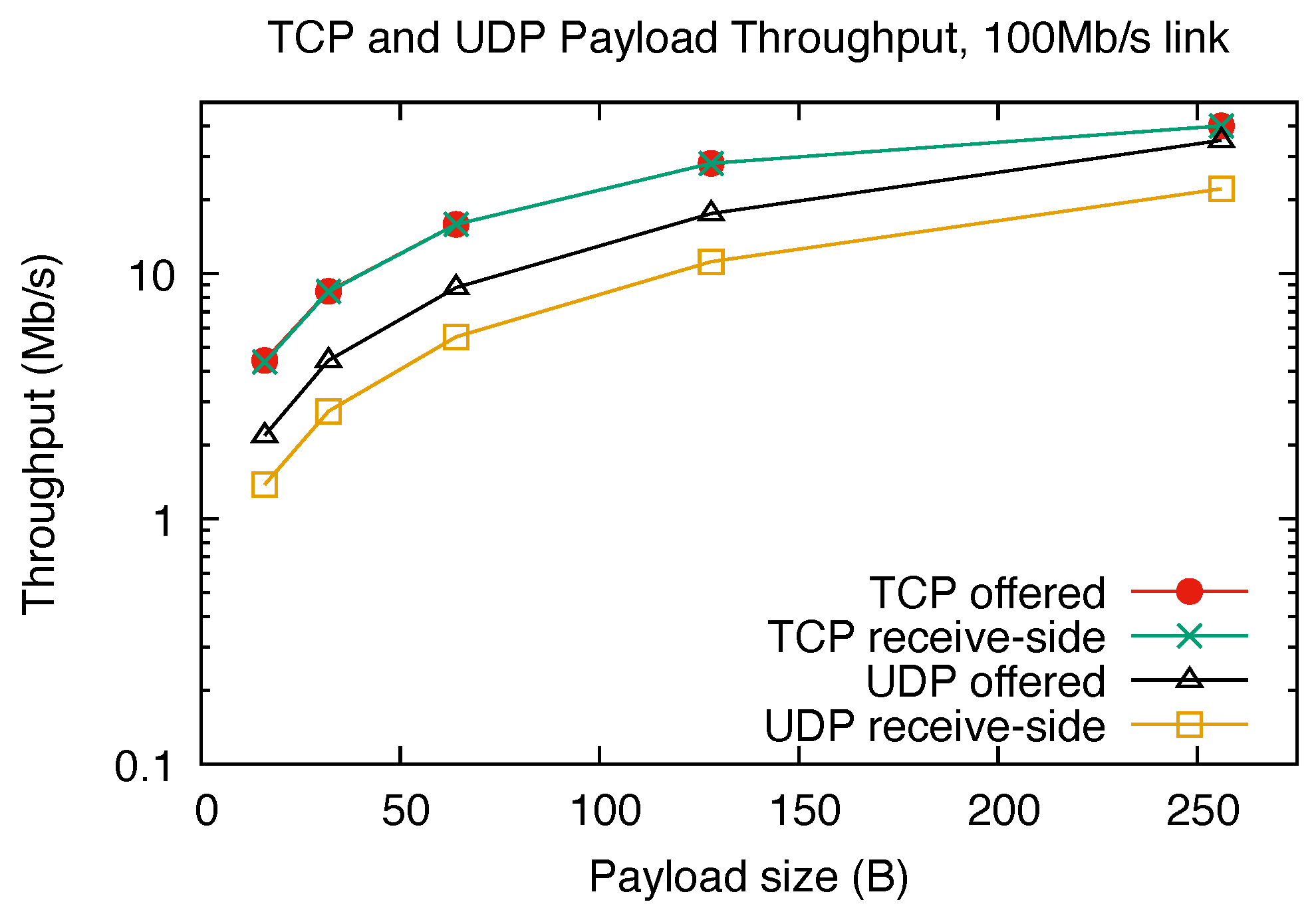
As a baseline for the subsequent evaluation of Modbus-TCP and Modbus-UDP performance, some preliminary tests were performed with the goal of assessing the maximum throughput the experimental boards could achieve when sending raw TCP and UDP payloads. To this purpose the standard iperf3 test program, version 3.9, was used with a measurement window of 60 s and offered bandwidth limit of 100 Mb/s, that is, the same as the link speed. Layer-4 (L4) payload sizes of 16, 32, 64, 128, and 256 bytes were used, consistently with the range of L4 payload sizes used in the Modbus experiments to be presented in Section 4.3 and Section 4.4.
Figure 6 shows the results. Generally speaking, TCP performs better than UDP in terms of throughput because, regardless of the payload size used when transmitting data, it is allowed to aggregate multiple payloads into a single TCP segment, thus achieving better efficiency. The presence of automatic back pressure in TCP causes the receive-side throughput (measured at the receiver ingress port) to always be equal to the offered throughput (measured at the transmitter egress port) with no data loss. On the contrary, UDP exerts no back pressure, which leads to datagram loss when the offered throughput exceeds what the receiver is able to handle.

4.3. Round-Trip Time

The round-trip time of a Modbus transaction is defined as the total time it takes for a request to travel from the master to the slave and the corresponding response from the slave to go back to the master. Being an endpoint-to-endpoint layer-7 delay, it also includes the protocol stack execution time on both the master and slave sides, plus any additional time the slave may need to execute the command it received from the master before it sends its response back.
It has been selected for the experiments because it is the most relevant metric to evaluate the performance of a master/slave protocol like Modbus. In fact, it directly affects the throughput it may achieve in terms of transactions and bits per second. Moreover, when the protocol is used to support a real-time control algorithm, its mean value represents the mean latency of data I/O from sensors and to actuators. Finally, its standard deviation, along with its minimum and maximum values, determine average and worst-case sensing and actuation jitter and are directly related to communication timing determinism.
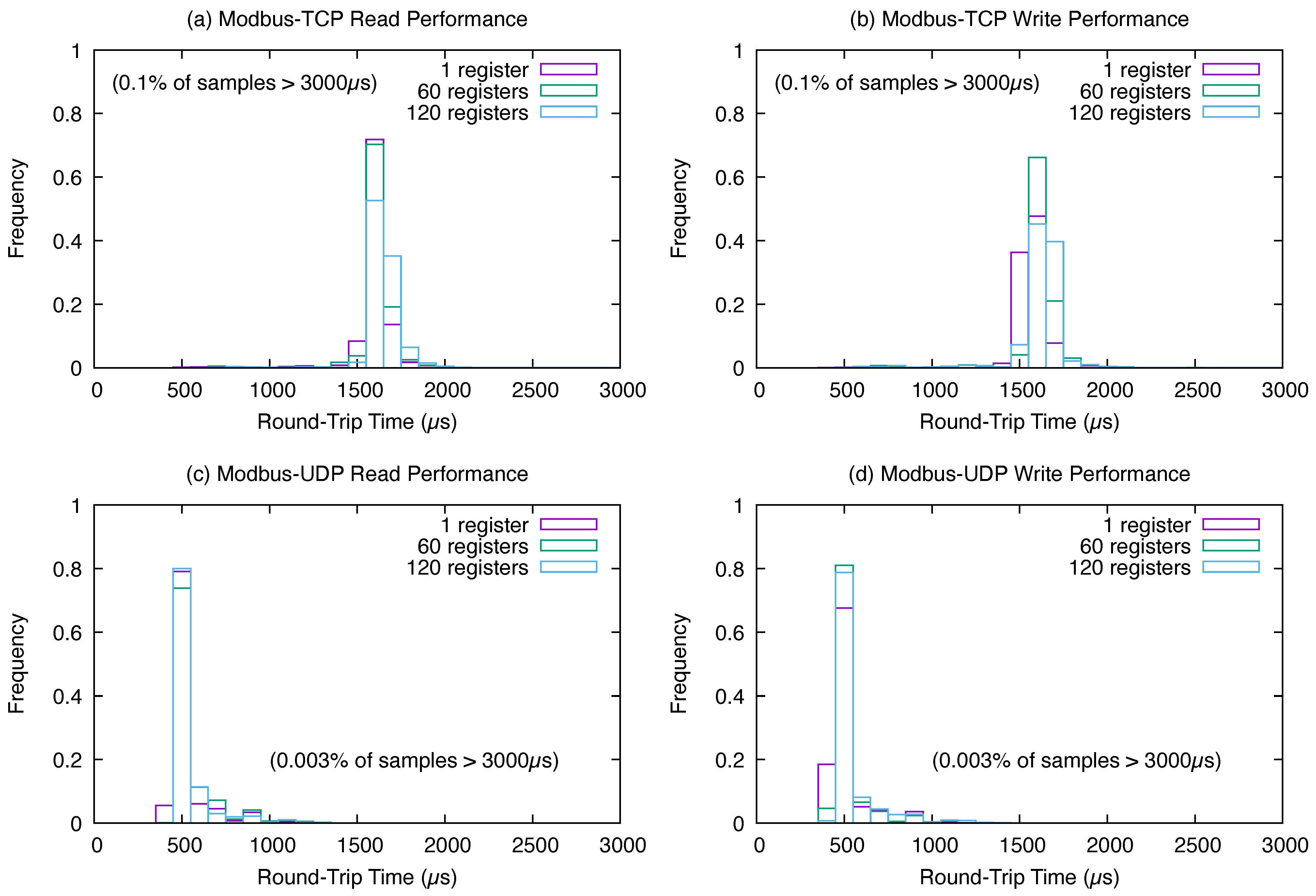
Figure 7 contains the Modbus-TCP and Modbus-UDP round-trip time histograms generated from n = 10,000 samples for data transfers from the slave to the master (RH transactions) and vice versa (WM transactions) as a function of the number of registers N exchanged. Sub-plots (a) and (b) pertain to Modbus-TCP, while (c) and (d) are for Modbus-UDP. The value N = 1 has been chosen because it maximizes protocol overheads, while the values N = 60 and N = 120 provide information on the influence N has on the round-trip time as it approaches the maximum number of registers the aforementioned transactions support. The histogram bin width was set to 100 µ s .
The corresponding summary information is listed in Table 3. For each test case, from left to right, the table lists the mean round-trip time ( μ ), its standard deviation ( σ ), and the minimum/maximum values observed during the test. The values of μ and σ were calculated from histogram data, so they are affected by the inherent discretization error that corresponds to a bin width of 100 µs. Moreover, all samples that fell out of the histogram range were attributed to its highest bin.
The first conclusion that can be drawn from the histograms is that N has negligible influence on the round-trip time regardless of the communication protocol. This was to be expected because, when N goes from 1 to 120, the length of the UDP datagrams or TCP segments to be transmitted increases by ( 120 1 ) 2 B = 238 B = 1904 b due to the fact that each Modbus register is 2 B in size. Hence, at a link speed of 100 M b / s , the additional datagram or segment transmission time is merely 1904 b / 100 M b / s = 19.04 µ s . This value amounts to about 3.9% of the minimum round-trip time recorded across all experiments, 490 µ s .
The second much more important observation is that μ UDP , the mean round-trip time of Modbus-UDP, is consistently less than 38% of μ TCP , the mean round-trip time of Modbus-TCP. Indeed, the maximum μ UDP is 609.60 µ s and the minimum μ TCP is 1613.60 µ s , leading to a worst-case ratio of 609.60 / 1613.60 = 0.38 . The fact that Modbus-TCP performs significantly worse than Modbus-UDP is corroborated by the comparison between the maximum (worst) round-trip times observed during the experiments. The maximum was consistently above 10,000 µ s for Modbus-TCP and below 5200 µ s for Modbus-UDP.
Furthermore, Table 4 lists the results of one-tailed t-tests for the equality of means at a significance level α = 0.001 , comparing μ UDP and μ TCP in the six test cases being considered. The null hypothesis is H 0 : μ UDP = μ TCP , and the alternate hypothesis is H 1 : μ UDP < μ TCP . The alternate hypothesis was accepted in all cases, thus confirming the statistical significance of the difference between the means. Last but not least, in all experiments, the fraction of samples that exceeded 3000 µ s , the upper bound of the histograms shown in Figure 7, was significantly higher ( 0.1 % ) for Modbus-TCP than for Modbus-UDP ( 0.003 % ).

4.4. Effect of Data Link Errors

The results shown and commented on in the previous section were obtained in a lab setting and hence with a negligible data link error probability. As a consequence, retransmission mechanisms were rarely exercised, if ever, during the experiments. To better evaluate the difference in performance between the automatic TCP segment retransmission of Modbus-TCP and the customized UDP datagram retransmission of Modbus-UDP, the same experiments were repeated with a simulated random packet loss probability p l = 10 2 in both directions of the full-duplex link between the boards. The simulation was performed by means of the built-in Linux kernel firewall configured, on both boards, with the command
          $ iptables -A INPUT -i eth0 -m statistic --mode random \
                   --probability 0.01 -j DROP
        
where eth0 is the name of the Ethernet interface used for the experiments.
Considering that each experiment collects n = 10,000 samples, each sample corresponds to one Modbus transaction, and each error-free transaction consists of two UDP datagrams or two TCP segments traveling in opposite directions if data link errors are assumed to be random and independent; this leads to an expected number of errors e = n · p l = 200 , according to a well-known property of the binomial distribution. In other words, the number of transactions that require a retransmission is expected to be e / n = 2 % of the total. This formula neglects second- and higher-order effects, that is, the possible occurrence of further errors during a retransmission triggered by an error.
Figure 8 summarizes the results obtained in the experimental conditions just described. As before, sub-plots (a) and (b) pertain to Modbus-TCP, while (c) and (d) are for Modbus-UDP. Table 5 lists the corresponding summary statistics. The comparison between this second set of experiments with respect to the error-free experiments described in Section 4.3 shows that data link errors affect Modbus-UDP and Modbus-TCP in different ways.
Namely, although errors affect the mean round-trip time of Modbus-UDP and Modbus-TCP in similar ways in absolute terms, increasing it by an amount in the range [ 113.55 , 194.32 ] µ s for Modbus-UDP and [ 117.43 , 240.13 ] µ s for Modbus-TCP, the effect on standard deviation is notably different, increasing it by a ratio in the range [ 4.09 , 5.39 ] for Modbus-UDP instead of the higher [ 5.10 , 7.49 ] for Modbus-TCP.
Denoting with σ UDP the standard deviation of Modbus-UDP and with σ TCP the one of Modbus-TCP, Table 6 presents the results of one-tailed F-tests for the equality of variances with significance level α = 0.001 , null hypothesis H 0 : σ UDP = σ TCP , and alternate hypothesis H 1 : σ UDP < σ TCP . The F-tests cover all the test cases being considered, and the alternate hypothesis was accepted in all cases, thus confirming the statistical significance of the difference between the standard deviations of Modbus-UDP and Modbus-TCP in the presence of data link errors.
Even more importantly for RT Class 3 (soft real-time) and Class 2 (hard real-time) systems, according to the classification proposed in [44], is the fact that, in the case of Modbus-TCP, a non-negligible fraction of samples led to a round-trip time well in excess of 10 ms and up into the hundreds of milliseconds, as shown in the rightmost column of Table 5. For the sake of illustration, these samples are represented by the wider bars at the extreme right of Figure 8a,b.
The fact that about 2% of the samples fell in this category, the same value as the expected number e of transactions affected by errors, leads to the observation that, whenever TCP segment retransmission is called into action, the round-trip time of Modbus-TCP transactions grows inordinately, to the point of exceeding the default transaction timeout of the Modbus master library used for the experiments. In fact, the timeout had to be adjusted to conduct these tests.
This phenomenon was not observed when using Modbus-UDP, whose worst-case round-trip time remained consistently below 10 ms across all experiments. The effect of datagram retransmission is indeed visible in Figure 8c,d as non-zero histogram bars located at approximately x = 4 ms , which is consistent with a nominal retransmission timeout t ( U ) = 3 ms , as specified in Section 3, plus protocol stack overheads. Similarly, the worst-case round-trip time of around 8 ms can be attributed to double retransmission.

4.5. Modbus-TCP and Modbus-UDP Throughput

The average Modbus-TCP throughput T TCP in b/s is defined as the ratio between the amount of data L 7 transferred in one transaction (Table 2), expressed in bits, and the mean round-trip time μ TCP (Table 3). The average Modbus-UDP throughput T UDP is defined in the same way:
T TCP = 8 L 7 / μ TCP , T UDP = 8 L 7 / μ UDP .
The throughput depends on the number of registers exchanged N and, marginally, on the kind of Modbus transaction (RH or WM). Figure 9 shows the results obtained in the experiments described in Section 4.3. For reference, the figure also shows the baseline TCP and UDP receive-side throughput measured as discussed in Section 4.2. In addition to the significant difference between T TCP and T UDP , which is a direct consequence of the difference between μ TCP and μ UDP through (5), two other facets of these results are worth mentioning:
  • The Modbus-TCP throughput T TCP is significantly lower than T UDP even though the baseline TCP throughput is significantly higher than the baseline UDP throughput. This discrepancy can be attributed to the fact that TCP data aggregation mechanisms, which enhanced throughput in the baseline tests, cannot be used when dealing with request–response transactions whose messages are significantly shorter than the maximum TCP segment size.
  • The Modbus-UDP throughput T UDP is still much lower than the baseline UDP throughput and never went beyond about 16% of it. The implications of this result are twofold. Firstly, it highlights the ineffectiveness of UDP datagram queuing and pipelining in request–response transactions. In fact, in this kind of transaction, any queues or pipelines that the protocol stack may put into effect are, by definition, completely drained at the end of each transaction. Secondly, it shows that Modbus protocol stack overheads above L4, as well as application-level message processing on both the master and slave side, are significant. In turn, this suggests that optimizing the protocol stack at this level may be the subject of future work.
Figure 9. Modbus-TCP and Modbus-UDP throughput, n = 10,000 samples.
Futureinternet 17 00356 g009

4.6. Sensitivity to Interfering Network Load

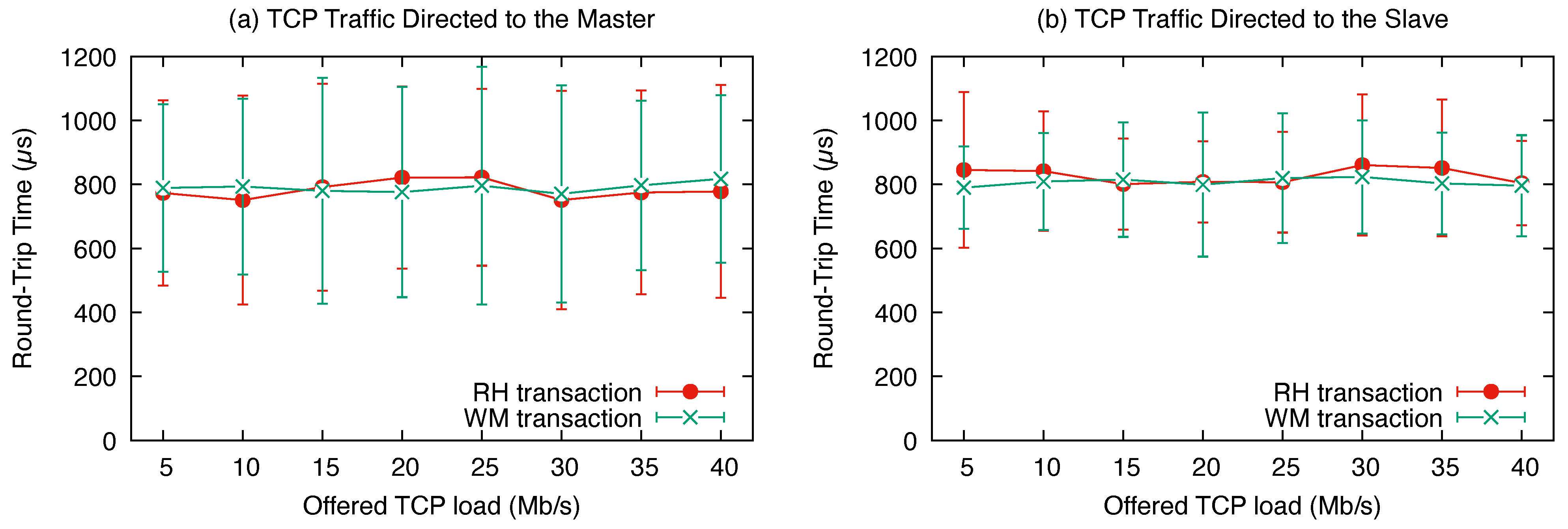
A set of experiments have been carried out to confirm the effectiveness of the packet prioritization mechanisms specified in Section 3.6 to shield Modbus-UDP communication from other traffic. These experiments are based on the same test programs previously discussed, configured to issue RH or WM transactions involving N = 120 registers, plus a varying network load.
The interfering network load has been generated by means of a TCP connection established by the iperf3 tool with payload length 256 B and an offered bandwidth from 5 Mb / s to 40 M b / s , the highest TCP load that the boards used for the experiments are able to sustain (as assessed in Section 4.2), in 5 M b / s intervals. The TCP connection involves data traffic being transmitted to the Modbus-UDP master or slave node. The experimental results are plotted in Figure 10a,b. They show that the interfering traffic has virtually no effect on the Modbus-UDP round-trip time in all scenarios covered by the tests.

4.7. Transmit and Receive Path Overhead

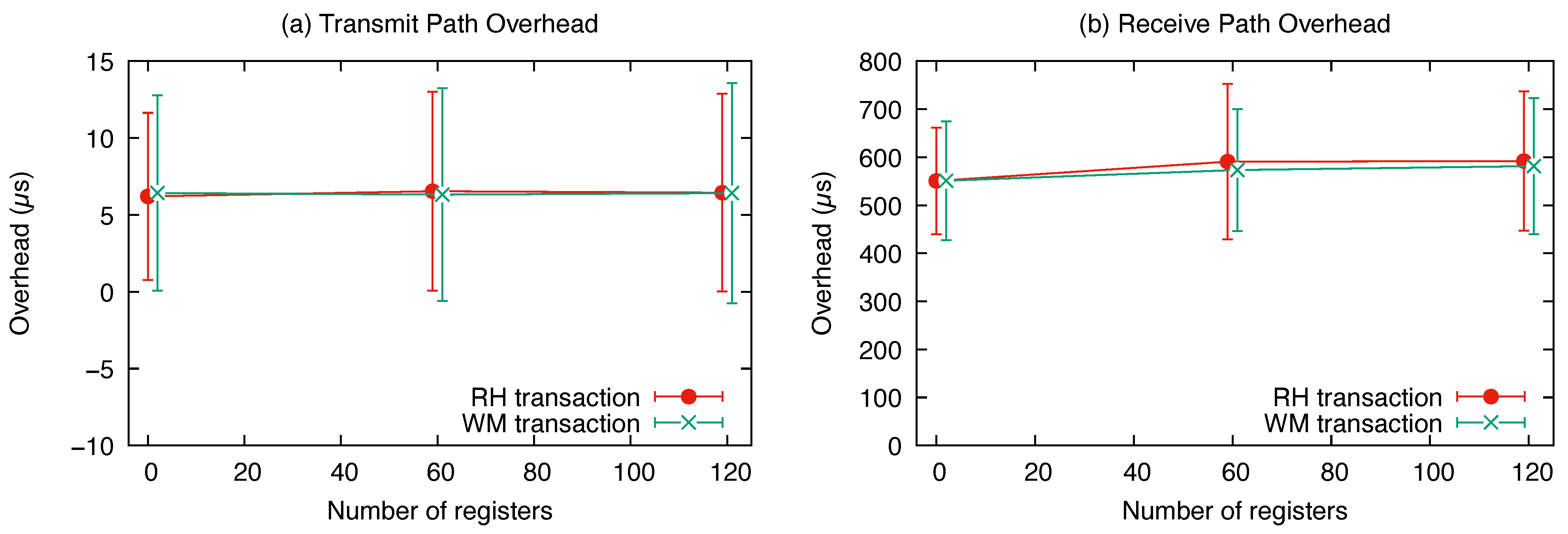
In the last set of experiments, the Linux/UDP port for Modbus Master was instrumented to measure its transit time along both the transmit and receive paths. By code inspection, it was determined that the overhead of the Linux/UDP port on the slave side was lower, and hence the measurements that were conducted also represent a conservative assessment of the overhead of the Linux/UDP port for FreeMODBUS. As in the previous experiments, the test programs were configured to issue RH or WM transactions with N = 1 , 60, and 120 registers. Figure 11 shows the results for the transmit (a) and receive (b) paths. These results complement the end-to-end round-trip time measurements commented on in Section 4.3 and are consistent with them.
An interesting observation that stems from the comparison is that the Modbus-UDP receive path overhead dominates the overall round-trip time. This is likely due to the use of inter-task message passing along the receive path, which is in turn implemented on top of a general-purpose POSIX mq message queue, a relatively heavyweight mechanism. This provides significant hints for further performance improvements, which could be the subject of future work. For instance, such a message queue could profitably be replaced by a more specialized and efficient mechanism based on mutual exclusion semaphores and condition variables.

5. Conclusions

This paper describes a novel redesign of the Modbus-UDP protocol. It addresses the main shortcomings of previous proposals that layered Modbus on top of a UDP transport. Namely, it reinstates the broadcast communication capability, which was lost as the Modbus protocol evolved towards Modbus-TCP, and introduces an automatic datagram loss detection and recovery mechanism that counteracts the inherently unreliable delivery of UDP datagrams.
The correct implementation of broadcast communication was confirmed by porting a broadcast-based protocol originally proposed for Modbus-RTU and Modbus-CAN [13] and verifying that it passed its test suite. In addition, the performance of the newly proposed Modbus-UDP design, in terms of throughput and resilience to data link errors, was compared against Modbus-TCP. To guarantee a fair comparison, the two protocols were tested within the same Modbus master–slave protocol stacks [28,29], on the same testbed, and with the same application test programs.
The experimental results, validated by suitable statistical hypothesis tests, show that Modbus-UDP achieves a mean round-trip time of only 38% with respect to Modbus-TCP and exhibits 50% of its standard deviation when subject to a 1% two-way IP datagram loss probability. Those results, combined with the lower overhead of UDP versus TCP well documented in literature, make the redesigned Modbus-UDP protocol better suited for a variety of IIoT systems with limited computing and communication resources.
Possible areas of future work include the design and implementation of a Modbus-UDP ↔ Modbus-RTU gateway along the lines described in [23] and making use of the version of Modbus-UDP proposed here, as well as the adaptation of the security enhancement techniques originally designed for CAN to Modbus-UDP. Moreover, a pilot study aimed at replacing Modbus-CAN with Modbus-UDP in a real-world industrial application is currently ongoing.

Funding

This research received no external funding.

Institutional Review Board Statement

Not applicable.

Informed Consent Statement

Not applicable.

Data Availability Statement

The original contributions presented in this study are included in the article. Further inquiries can be directed to the corresponding author.

Conflicts of Interest

The author declares no conflicts of interest.

References

  1. Modbus-IDA. MODBUS Application Protocol Specification V1.1b; Modbus-IDA: Westford, MA, USA, 2006; Available online: https://www.modbus.org/docs/Modbus_Application_Protocol_V1_1b.pdf (accessed on 29 July 2025).
  2. Modbus-IDA. MODBUS over Serial Line Specification and Implementation Guide V1.02; Modbus-IDA: Westford, MA, USA, 2006; Available online: https://www.modbus.org/docs/Modbus_over_serial_line_V1_02.pdf (accessed on 29 July 2025).
  3. TIA. Electrical Characteristics of Generators and Receivers for Use in Balanced Digital Multipoint Systems (ANSI/TIA/EIA-485-A-98) (R2003); Telecommunications Industry Association: Arlington, VA, USA, 1998. [Google Scholar]
  4. TIA. Interface Between Data Terminal Equipment and Data Circuit-Terminating Equipment Employing Serial Binary Data Interchange (ANSI/TIA-232-F-1997) (R2002); Telecommunications Industry Association: Arlington, VA, USA, 1997. [Google Scholar]
  5. Jayalaxmi, P.; Saha, R.; Kumar, G.; Kumar, N.; Kim, T.H. A Taxonomy of Security Issues in Industrial Internet-of-Things: Scoping Review for Existing Solutions, Future Implications, and Research Challenges. IEEE Access 2021, 9, 25344–25359. [Google Scholar] [CrossRef]
  6. Calderón, D.; Folgado, F.J.; González, I.; Calderón, A.J. Implementation and Experimental Application of Industrial IoT Architecture Using Automation and IoT Hardware/Software. Sensors 2024, 24, 8074. [Google Scholar] [CrossRef]
  7. Cena, G.; Cibrario Bertolotti, I.; Hu, T.; Valenzano, A. Design, verification, and performance of a MODBUS-CAN adaptation layer. In Proceedings of the 10th IEEE International Workshop on Factory Communication Systems (WFCS), Toulouse, France, 5–7 May 2014; pp. 1–10. [Google Scholar] [CrossRef]
  8. Modbus-IDA. MODBUS Messaging on TCP/IP Implementation Guide V1.0b; Modbus-IDA: Westford, MA, USA, 2006; Available online: https://www.modbus.org/docs/Modbus_Messaging_Implementation_Guide_V1_0b.pdf (accessed on 29 July 2025).
  9. Johansson, R. Libmodbus, Open-Source Library for MODBUS TCP and UDP. Available online: https://libmodbus.org;https://github.com/rscada/libmodbus (accessed on 14 July 2025).
  10. Wimberger, D. Java Modbus Library. Available online: https://sourceforge.net/projects/jamod/ (accessed on 14 July 2025).
  11. ISO 11898-1:2024; Road Vehicles–Controller Area Network (CAN)—Part 1: Data Link Layer and Physical Signalling. International Organization for Standardization: Geneva, Switzerland, 2024.
  12. Postel, J. (Ed.) Transmission Control Protocol—DARPA Internet Program Protocol Specification, RFC 793; USC/Information Sciences Institute (ISI): Marina Del Rey, CA, USA, 1981. [Google Scholar]
  13. Cena, G.; Cibrario Bertolotti, I.; Hu, T. Formal Verification of a Distributed Master Election Protocol. In Proceedings of the 9th IEEE International Workshop on Factory Communication Systems (WFCS), Lemgo/Detmold, Germany, 21–24 May 2012; pp. 245–254. [Google Scholar]
  14. Liu, X.; Cheng, L.; Bhargava, B.; Zhao, Z. Experimental Study of TCP and UDP Protocols for Future Distributed Databases; Technical Report 95-046; Department of Computer Science, Purdue University: West Lafayette, IN, USA, 1995. [Google Scholar]
  15. Silva, C.R.M.; Silva, F.A.C.M. An IoT Gateway for Modbus and MQTT Integration. In Proceedings of the 2019 SBMO/IEEE MTT-S International Microwave and Optoelectronics Conference (IMOC), Aveiro, Portugal, 10–14 November 2019; pp. 1–3. [Google Scholar] [CrossRef]
  16. John, T.; Vorbröcker, M. Enabling IoT connectivity for ModbusTCP sensors. In Proceedings of the 2020 25th IEEE International Conference on Emerging Technologies and Factory Automation (ETFA), Vienna, Austria, 8–11 September 2020; Volume 1, pp. 1339–1342. [Google Scholar] [CrossRef]
  17. Elamanov, S.; Son, H.; Flynn, B.; Yoo, S.K.; Dilshad, N.; Song, J. Interworking between Modbus and internet of things platform for industrial services. Digit. Commun. Netw. 2024, 10, 461–471. [Google Scholar] [CrossRef]
  18. He, Y.; Lv, X. The Application of Modbus TCP in Universal Testing Machine. In Proceedings of the 2021 IEEE 5th Advanced Information Technology, Electronic and Automation Control Conference (IAEAC), Chongqing China, 12–14 March 2021; Volume 5, pp. 1878–1881. [Google Scholar] [CrossRef]
  19. Li, Y.; Ma, Y.; Chen, M.; Wang, C. A Power IoT Terminal Asset Identification Technology Suitable for Modbus Protocol. In Proceedings of the 2024 International Conference on Interactive Intelligent Systems and Techniques (IIST), Bhubaneswar, India, 4–5 March 2024; pp. 224–228. [Google Scholar] [CrossRef]
  20. Künzel, G.; Corrêa Ribeiro, M.A.; Pereira, C.E. A tool for response time and schedulability analysis in Modbus serial communications. In Proceedings of the 2014 12th IEEE International Conference on Industrial Informatics (INDIN), Porto Alegre, RS, Brazil, 27–30 July 2014; pp. 446–451. [Google Scholar] [CrossRef]
  21. Rodríguez-Pérez, N.; Domingo, J.M.; López, G.L.; Stojanovic, V. Scalability Evaluation of a Modbus TCP Control and Monitoring System for Distributed Energy Resources. In Proceedings of the 2022 IEEE PES Innovative Smart Grid Technologies Conference Europe (ISGT-Europe), Novi Sad, Serbia, 10–12 October 2022; pp. 1–6. [Google Scholar] [CrossRef]
  22. Reid, S.; Marceau, M.; Filler, K.; Mecham, K.D.; Whitaker, B.M. Supervised Machine Learning for Modbus Communication Protocol Decoding. In Proceedings of the 2025 Intermountain Engineering, Technology and Computing (IETC), Orem, UT, USA, 9–10 May 2025; pp. 1–4. [Google Scholar] [CrossRef]
  23. Zhao, S.; Zhang, Q.; Zhao, Q.; Zhang, X.; Guo, Y.; Lu, S.; Song, L.; Zhao, Z. Enhancing Bidirectional Modbus TCP ↔ RTU Gateway Performance: A UDP Mechanism and Markov Chain Approach. Sensors 2025, 25, 3861. [Google Scholar] [CrossRef] [PubMed]
  24. Găitan, N.C.; Zagan, I.; Găitan, V.G. Proposed Modbus Extension Protocol and Real-Time Communication Timing Requirements for Distributed Embedded Systems. Technologies 2024, 12, 187. [Google Scholar] [CrossRef]
  25. Găitan, V.G.; Zagan, I.; Găitan, N.C. Modbus RTU Protocol Timing Evaluation for Scattered Holding Register Read and ModbusE-Related Implementation. Processes 2025, 13, 367. [Google Scholar] [CrossRef]
  26. Chakraborty, S.; Aithal, P.S. Industrial Automation Debug Message Display Over Modbus RTU Using C#. Int. J. Manag. Technol. Soc. Sci. (IJMTS) 2023, 8, 305–313. [Google Scholar] [CrossRef]
  27. Krakora, J. Basic Functionality of the Modbus TCP and UDP Based Protocol Using PHP. Available online: https://github.com/krakorj/phpmodbus (accessed on 14 July 2025).
  28. Walter, C. FreeMODBUS—A Modbus ASCII/RTU and TCP Implementation. Available online: http://freemodbus.berlios.de/ (accessed on 16 June 2025).
  29. Embedded Solutions. Modbus Master. Available online: http://www.embedded-solutions.at/ (accessed on 19 May 2025).
  30. Iyengar, J.; Thomson, M. QUIC: A UDP-Based Multiplexed and Secure Transport; Internet Engineering Task Force (IETF): Fremont, CA, USA, 2021; Available online: https://datatracker.ietf.org/doc/rfc9000/ (accessed on 29 July 2025). [CrossRef]
  31. Luxemburk, J.; Hynek, K.; Čejka, T.; Lukačovič, A.; Šiška, P. CESNET-QUIC22: A large one-month QUIC network traffic dataset from backbone lines. Data Brief 2023, 46, 108888. [Google Scholar] [CrossRef]
  32. Simpson, A.; Alshaali, M.; Tu, W.; Asghar, M.R. Quick UDP Internet Connections and Transmission Control Protocol in unsafe networks: A comparative analysis. IET Smart Cities 2024, 6, 351–360. [Google Scholar] [CrossRef]
  33. CS536-Modbus-QUIC. Available online: https://github.com/CS536-Modbus-QUIC (accessed on 30 July 2025).
  34. Schneider Electric. MODBUS/TCP Security Protocol Specification; Schneider Electric: Andover, MA, USA, 2018; Available online: https://modbus.org/docs/MB-TCP-Security-v21_2018-07-24.pdf (accessed on 29 July 2025).
  35. Rescorla, E.; Dierks, T. The Transport Layer Security (TLS) Protocol Version 1.2; Internet Engineering Task Force (IETF): Fremont, CA, USA, 2008; Available online: https://datatracker.ietf.org/doc/html/rfc5246 (accessed on 29 July 2025). [CrossRef]
  36. Thomson, M.; Turner, S. Using TLS to Secure QUIC; Internet Engineering Task Force (IETF): Fremont, CA, USA, 2021; Available online: https://datatracker.ietf.org/doc/html/rfc9001 (accessed on 29 July 2025). [CrossRef]
  37. Helmy, M.; Samy, M.T.; Azab, K.A. Advanced Security Solutions for CAN Bus Communications in AUTOSAR. In Proceedings of the 2024 International Conference on Computer and Applications (ICCA), Cairo, Egypt, 17–19 December 2024; pp. 1–6. [Google Scholar] [CrossRef]
  38. IEEE. ISO/IEC/IEEE International Standard: Telecommunications and Exchange Between Information Technology Systems–Requirements for Local and Metropolitan Area Networks—Part 1Q: Bridges and Bridged Networks; IEEE: Piscataway, NJ, USA, 2024. [Google Scholar] [CrossRef]
  39. Cena, G.; Cereia, M.; Cibrario Bertolotti, I.; Scanzio, S. A Modbus Extension for Inexpensive Distributed Embedded Systems. In Proceedings of the 8th IEEE International Workshop on Factory Communication Systems (WFCS), Nancy, France, 18–21 May 2010; pp. 251–260. [Google Scholar]
  40. Nichols, K.; Blake, S.; Baker, F.; Black, D. Definition of the Differentiated Services Field (DS Field) in the IPv4 and IPv6 Headers; Internet Engineering Task Force (IETF): Fremont, CA, USA, 1998; Available online: https://datatracker.ietf.org/doc/html/rfc2474 (accessed on 29 July 2025).
  41. BeagleBoard.org Foundation. BeagleBone® Black; BeagleBoard.org Foundation: Michigan, IN, USA. Available online: https://www.beagleboard.org/boards/beaglebone-black (accessed on 26 June 2025).
  42. Texas Instruments, Inc. AM335x and AMIC110 Sitara™ Processors Technical Reference Manual; Texas Instruments, Inc.: Dallas, TX, USA, 2019. [Google Scholar]
  43. ARM, Ltd. ARM® Architecture Reference Manual for A-Profile Architecture; ARM, Ltd.: Cambridge, UK, 2025. [Google Scholar]
  44. Neumann, P. Communication in industrial automation—What is going on? Control Eng. Pract. 2007, 15, 1332–1347. [Google Scholar] [CrossRef]
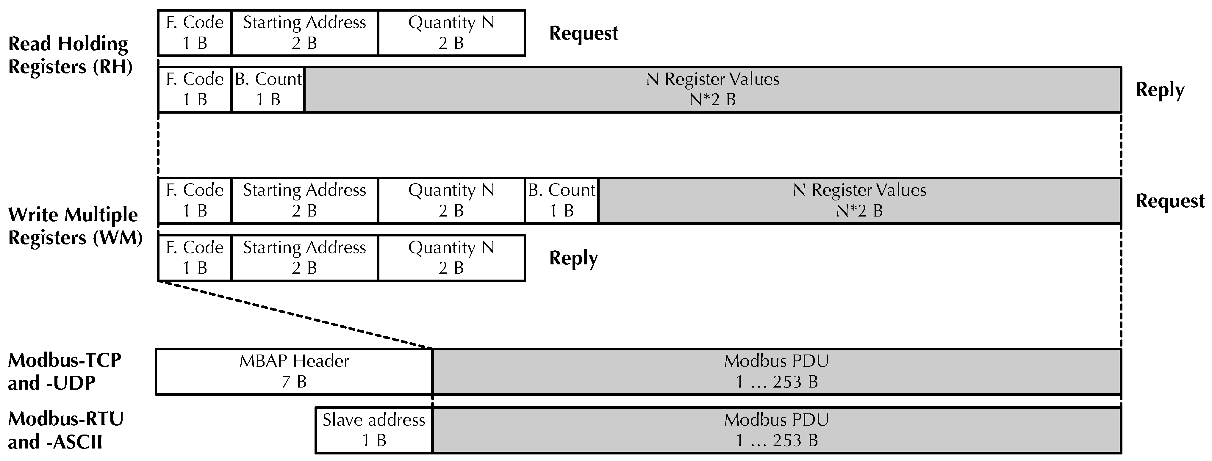
Figure 1. Typical Modbus PDUs and transport-dependent headers (field width not to scale).
Futureinternet 17 00356 g001
Figure 2. Typical four-layer IIoT architecture with its associated software and hardware. The layers where Modbus is currently employed are highlighted in gray.
Futureinternet 17 00356 g002
Figure 3. Modbus-UDP frame format and its encapsulation into 100BaseTX Ethernet packets (field width not to scale).
Futureinternet 17 00356 g003
Figure 4. MBAP header and TID in Modbus-UDP.
Futureinternet 17 00356 g004
Figure 5. Hardware and software testbed used for performance evaluation.
Futureinternet 17 00356 g005
Figure 6. TCP and UDP payload throughput, 100 Mb/s full-duplex Ethernet link, iperf3, 60 s measurement window.
Futureinternet 17 00356 g006
Figure 7. Modbus-TCP and Modbus-UDP round-trip time histograms for RH and WM transactions as a function of N, the number of registers exchanged. Negligible link error probability, n = 10,000 samples per plot.
Futureinternet 17 00356 g007
Figure 8. Modbus-TCP and Modbus-UDP round-trip time histograms for RH and WM transactions as a function of the number of registers exchanged. Link error probability p l = 10 2 , n = 10,000 samples per plot.
Futureinternet 17 00356 g008
Figure 10. Sensitivity of RH and WM transactions with N = 120 registers to varying TCP network load directed to the Modbus master (a) and slave (b) nodes. Traffic generated with iperf3 with payload length (-l option) 256 B , n = 10,000 samples.
Futureinternet 17 00356 g010
Figure 11. Modbus-UDP transmit (a) and receive (b) path overhead in the Modbus Master protocol stack as a function of the kind of transaction and number of registers N, n = 10,000 samples.
Futureinternet 17 00356 g011
Table 1. L1 packet length L 1 of RH and WM transactions, in bytes.
RH TransactionWM Transaction
N Request Response Total Request Response Total
L 1 ( RH , S ) L 1 ( RH , R ) L 1 ( RH ) L 1 ( WM , S ) L 1 ( WM , R ) L 1 ( WM )
172721447372145
607218725919172263
1207230737931172383
Table 2. L4 payload length L 7 of RH and WM transactions, in bytes.
RH TransactionWM Transaction
N Request Response Total Request Response Total
L 7 ( RH , S ) L 7 ( RH , R ) L 7 ( RH ) L 7 ( WM , S ) L 7 ( WM , R ) L 7 ( WM )
1121123151227
601212914113312145
1201224926125312265
Table 3. Summary statistics of the data shown in Figure 7.
ProtocolR/W N μ ( μ s) σ ( μ s) Min ( μ s) Max ( μ s)
Modbus-TCPR11649.08209.6351312,317
Modbus-TCPR601667.15167.3260511,287
Modbus-TCPR1201700.70188.8973410,363
Modbus-TCPW11615.28193.3849012,503
Modbus-TCPW601662.86225.0556112,949
Modbus-TCPW1201676.69217.3753811,924
Modbus-UDPR1580.00105.644771353
Modbus-UDPR60609.60130.154901518
Modbus-UDPR120591.87117.425054962
Modbus-UDPW1565.15112.804821336
Modbus-UDPW60578.02112.924885142
Modbus-UDPW120601.35131.834921852
Table 4. One-tailed t-tests for the equality of means, comparing μ UDP and μ TCP at significance level α = 0.001 . H 0 : μ UDP = μ TCP , H 1 : μ UDP < μ TCP .
Test Case
R/W N Conf. int. of μ UDP μ TCP ( μ s)Accept
R1 [ , 1061.8 ] H 1
R60 [ , 1051.0 ] H 1
R120 [ , 1102.0 ] H 1
W1 [ , 1043.2 ] H 1
W60 [ , 1077.1 ] H 1
W120 [ , 1067.5 ] H 1
Table 5. Summary statistics of the data shown in Figure 8.
ProtocolR/W N μ ( μ s) σ ( μ s) Min ( μ s) Max ( μ s)
Modbus-TCPR11836.761253.06526487,738
Modbus-TCPR601839.951180.89550298,533
Modbus-TCPR1201835.401172.27557443,298
Modbus-TCPW11819.591174.32531417,290
Modbus-TCPW601818.131147.78612416,851
Modbus-TCPW1201855.411247.55550448,144
Modbus-UDPR1723.15547.654278242
Modbus-UDPR60731.58543.424608039
Modbus-UDPR120759.47569.084688411
Modbus-UDPW1724.23561.194417874
Modbus-UDPW60748.72552.164568297
Modbus-UDPW120745.42539.764688026
Table 6. One-tailed F-tests for the equality of standard deviations, comparing σ UDP and σ TCP at significance level α = 0.001 . H 0 : σ UDP = σ TCP , H 1 : σ UDP < σ TCP .
Test Case
R/W N Conf. int. of σ UDP / σ TCP Accept
R1 [ 0 , 0.4508 ] H 1
R60 [ 0 , 0.4746 ] H 1
R120 [ 0 , 0.5007 ] H 1
W1 [ 0 , 0.4929 ] H 1
W60 [ 0 , 0.4962 ] H 1
W120 [ 0 , 0.4462 ] H 1
Disclaimer/Publisher’s Note: The statements, opinions and data contained in all publications are solely those of the individual author(s) and contributor(s) and not of MDPI and/or the editor(s). MDPI and/or the editor(s) disclaim responsibility for any injury to people or property resulting from any ideas, methods, instructions or products referred to in the content.