1. Introduction
In the modern day, iCloud data transmission replaces the physical mail to speed up the time spent on exchanging information. Needless to mention, the Internet is a key element in the transmission process. Digital activities involving both the virtual world and the physical world can be foreseen in the near future, such as if a hospital technician uploads an X-ray image, a CT scan photo, or a patient’s information to a data center for a list of specific doctors to download them in order to discuss various treatments over an online meeting. To protect the privacy of the patient, no one should be able to see the information other than the related doctors. Encrypting and decrypting digital information are becoming more and more important in order to increase security. At the same time, there can be diagnostics information to be passed to one or some particular doctors. Data hiding then plays another crucial role in these data transitions [
1,
2].
When a content owner wants to send an image to a data receiver, the owner would like to add a secret message in the image before transmitting it to the receiver. Adding the secret message normally needs to go through a data hider, and as it may not be desirable for the data hider to see the image content, the owner encrypts the image before sending it in order to hide the message. A receiver holding the encryption key can recover the image, and a receiver with the data hiding key can extract the secret information.
There are various data hiding schemes designed to protect data effectively in different application circumstances that have demonstrated exceptional results. Data hiding has branched out into reversible data hiding (RDH) [
3,
4,
5,
6,
7] and non-reversible data hiding depending on whether the image content can be recovered or not. According to the hiding carriers, the hiding schemes can be cataloged into four different domains: spatial, frequency, compression, and encryption. When in the spatial domain, digital cover images are modified directly to embed data. As for the frequency domain, images are transformed using wavelet transform methods before embedding data. Images are first compressed with compression techniques prior to embedding information in the compression domain. In the encryption domain, images are encrypted using encryption keys before being sent to the data hider to hide secrets in the encrypted image. Data hiding in encrypted images (DH-EI) combines cryptography and DH technology to achieve higher levels of protection. DH-EI has branched out into reserving room before encryption (RRBE) and vacating room after encryption (VRAE) depending on the timing of room vacating.
Ma et al. [
8] proposed a reversible method for data hiding in encrypted images by preserving room before encryption in 2013. Yi and Zhou proposed a parameter-controlled method to embed data to encrypted images in 2018 [
9,
10]. Around the same time, Pauline and William [
11] proposed a method using MSB prediction and gained high embedding capacity by hiding data in encrypted images. Chen et al. [
12], in 2020, further improved the method by proposing a multi-MSB compression method. Puteaux and Puech [
13] proposed a fully reversible method by including the MSB error prediction and a reversible adaption in 2020, and Wu et al. [
14] proposed an improved version shortly after. Even though RRBE has a higher embedding capacity amount, owners may not have enough knowledge of how to go through the reserving process. Therefore, VRAE schemes still gain popularity among these types of applications to better secure information privacy.
In the VRAE scheme, the content owner performs only the operation of encrypting the image and then transmits the encrypted image to the data hider. After obtaining the encrypted image, the data hider vacates the room and embeds the data. Hong et al. [
15] proposed a DH-EI method that combined side match and block-wise LSB flipping. Zhang [
16] proposed a scheme to preserve space by utilizing compressed LSB planes, but the embedding capacity of this method was relatively low. Qian and Zhang [
17] proposed a method to reserve embedded rooms using distributed source coding. In 2014, joint and separable DH-EI schemes using bit flipping and prediction error techniques were proposed by Wu and Sun [
18]. Hung et al. [
19], in 2016, proposed a DH-EI framework for encrypting images using block-wise stream cipher and shuffling. Since block-wise stream cipher and shuffling are used, the correlation between encrypted blocks of pixels is preserved so that DH techniques can be used directly in the encryption domain. In 2018, Ge et al. [
20] combined the block-wise stream cipher and selected peaks for histogram shifting. In 2020, Bhardwaj and Aggarwal [
21] used an improved block-based joint DHEI algorithm to obtain higher embedding rates. In 2022, Wang et al. [
22] proposed a method to embed secret data using rotated pixel-blocks. Yu et al. [
23] used MSB replacements to embed data and then used the complexity among neighboring pixels to restore the image.
Our novel scheme focuses on using VRAE to hide data and incorporates vector quantization codeword index reordering [
4], Stream Cipher, and LSB replacement [
5] techniques to implement the scheme. Our research goal is to achieve a larger embedding capacity than other methods without degrading the visual quality of recovered images. The core contributions of the scheme are described below:
The scheme offers large embedding capacity.
It sustains the visual quality of encrypted images.
Extracting secret messages and recovering images can be independent.
The rest of the paper is structured as follows:
Section 2 discusses the Background of the Works, including the LSB encryption, the applied sorting, and the key index reordering method.
Section 3 describes the details of the novel scheme, and
Section 4 shows the experiments conducted and their analyses. Finally,
Section 5 is the conclusion.
2. Background of the Work
Our novel scheme employs the principal idea of a vector quantization (VQ) codeword index reordering scheme [
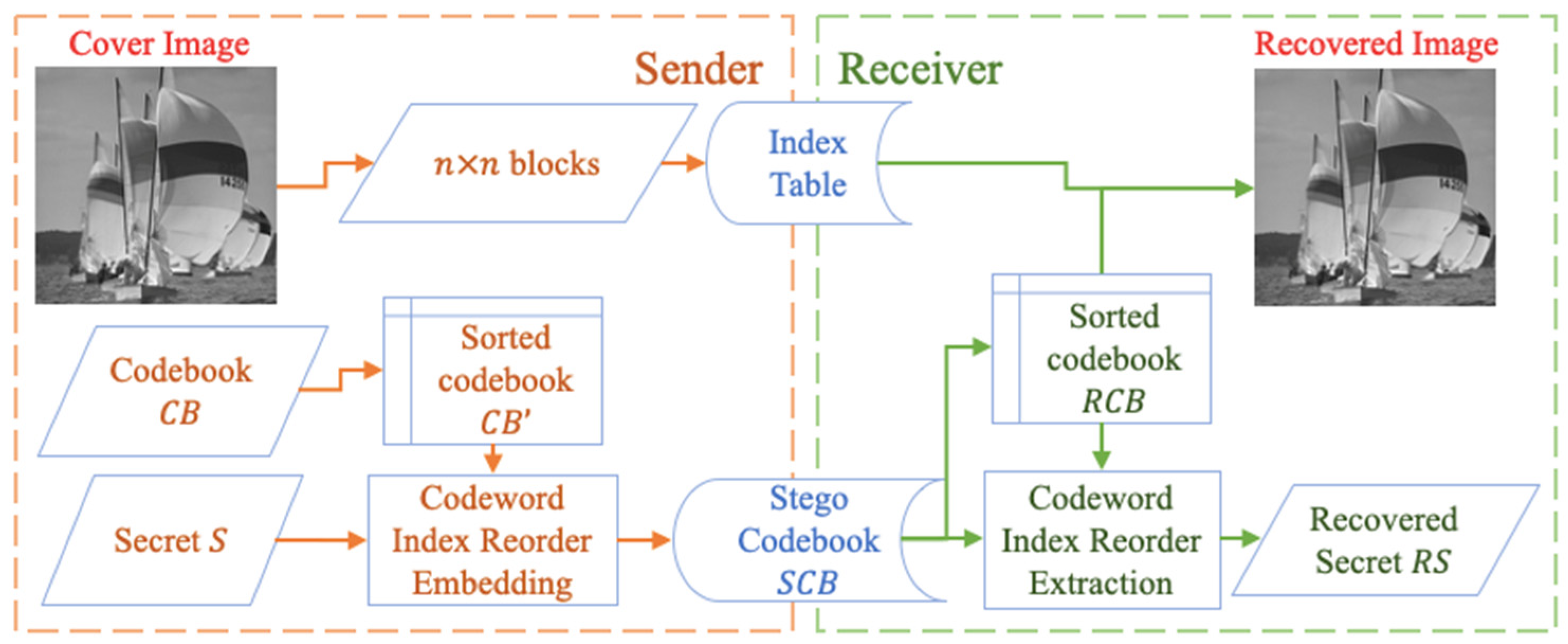
4] as the basic technique to embed and extract data. This section describes the data embedding and data extraction using the codeword index reordering.
When there is a codebook, it is sorted first before embedding secret data. The data is embedded through the new indices in a stego codebook.
Figure 1 indicates the flow of the codeword index reordering scheme including data embedding, data extraction, and image recovery. The stego codebook with the new ordered indices is then sent to receivers to extract the data.
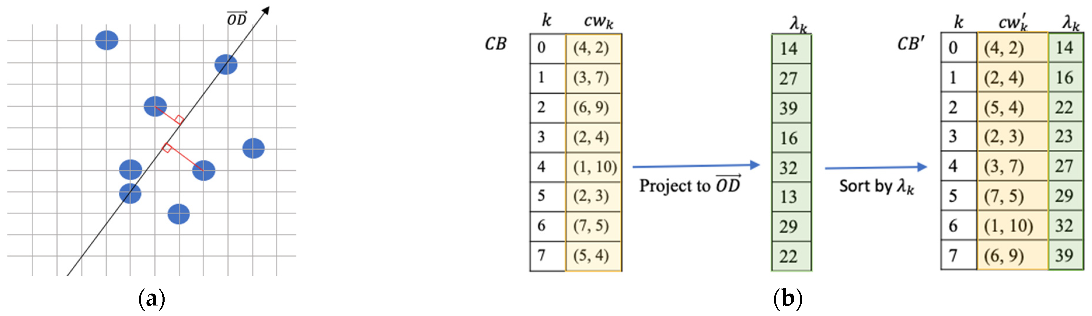
2.1. Sort Codewords by Projected Values
A sorted codebook is an essential component for a codeword index reordering scheme [
4]. There is a VQ codebook
, where
is the number of the codewords in the codebook. A data hider will find an n-dimensional point
, where
are randomly generated using a random seed. A line
connecting
and the origin
is a line that codewords in a codebook can project and obtain their projected values. These projected values are denoted as
,
, …,
using Equation (1) and are to be used to sort the codewords in the codebook.
The codebook is sorted and resulted to a sorted codebook .
An example of a codebook consisting of eight two-dimensional codewords is demonstrated in
Figure 2 to provide a better understanding of the projected values and the sorting result according to their projected values.
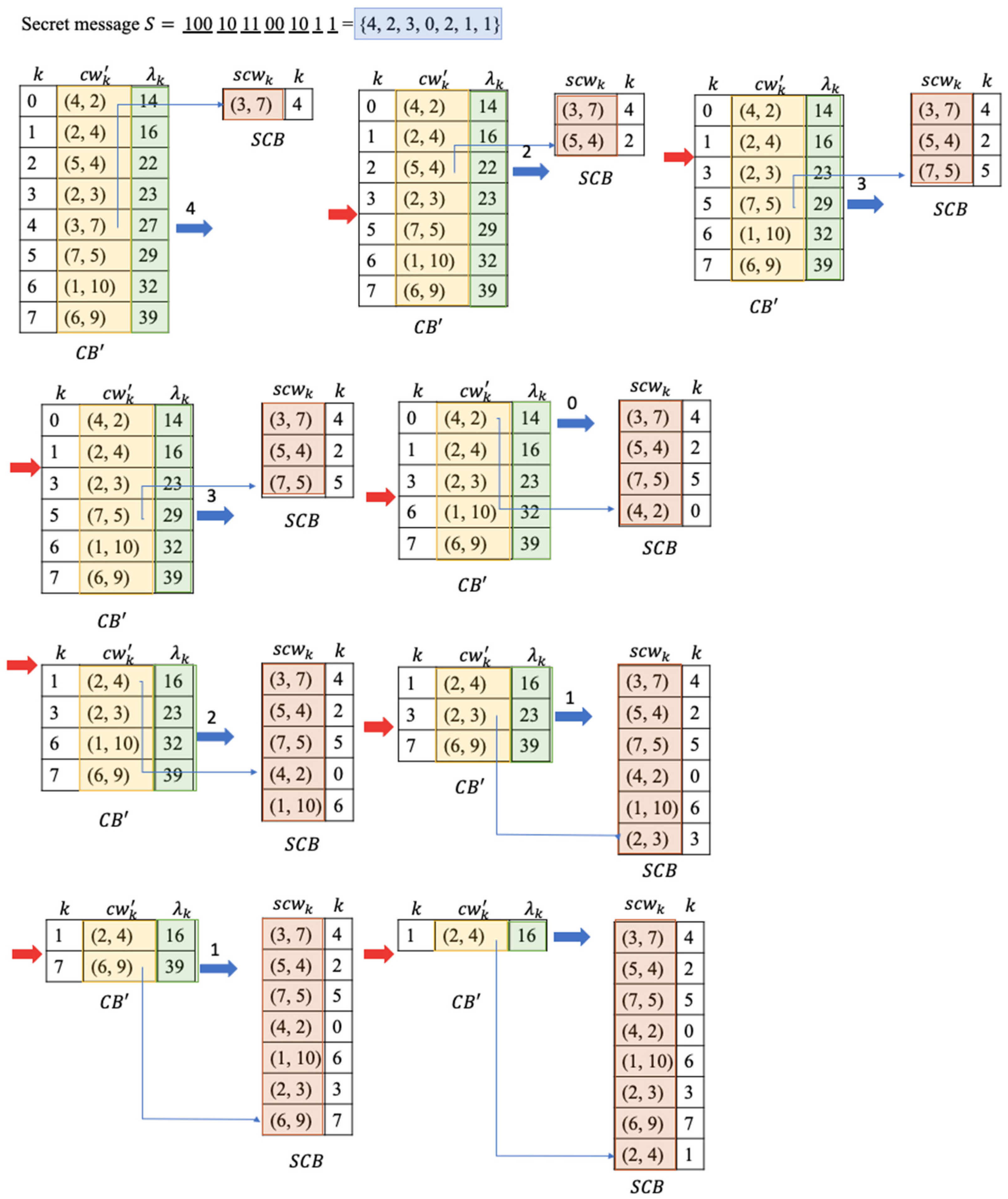
2.2. Data Embedding of the Codeword Index Reordering
When there is a secret data , the embedding procedure is organized as follows:
Step 1: Initialize a stego codebook .
Step 2: Calculate the number of bits to embed
Step 3: Convert secret bits to a decimal index
Step 4: Move the codeword out from and add to .
Step 5: Repeat Step 2 through Step 4 until there are no codewords in .
Step 6: Send to receivers.
Using the example in
Figure 1, the embedding results are illustrated in
Figure 3.
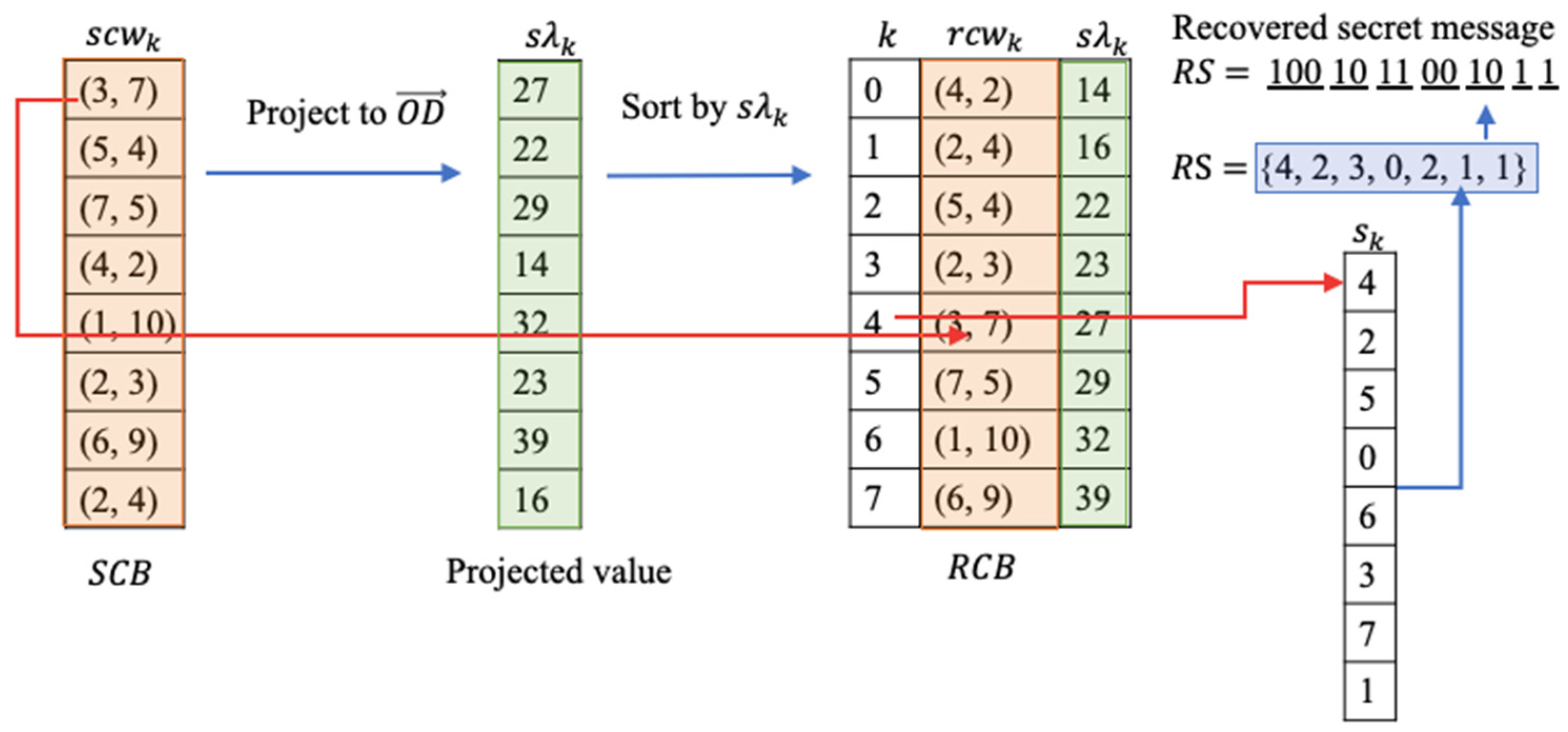
2.3. Data Extraction of the Codeword Index Reordering
When a receiver receives a stego codebook , the stego codebook needs to be sorted by the projected values of codewords using the received projecting line before extracting secret data. The following steps showing how the secret data are extracted:
Step 1: Project the codewords in to the line and sort the codebook by using the projected values of the codewords to obtain the recovered codebook .
Step 2: Initialize recovered secret .
Step 3: Initialize the current codeword index c to 0.
Step 4: Match the current codeword with the codewords in the recovered codebook and obtain the index in the .
Step 5: Convert to a binary bit stream .
Step 6: Append to .
Step 7: Increase the current codeword index c by 1.
Step 8: Repeat Step 4 through Step 7 until all codewords in are exhausted.
Continuing to use the example above,
Figure 4 demonstrates how the data are extracted from the stego codebook
.
3. Proposed Scheme
To protect the privacy of original cover images, our novel scheme encrypts the cover image before data embedding using an encryption key. A content owner sends the encrypted image to a data hider to hide secret messages. The data hider sends the marked images, the encryption key and the data hiding key to designated receivers after hiding data. In order to be able to simulate the codeword table to manipulate index order as the codeword index reordering scheme in
Section 2 Background of the Work,
Section 3.2 Codeword Table Formation describes how codeword tables are generated.
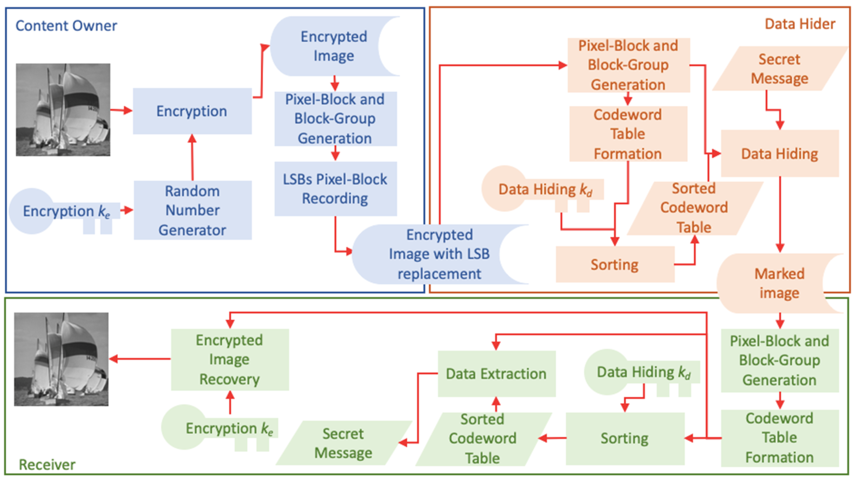
Figure 5 shows the framework of the proposed scheme. The content owner uses an encryption key
to activate a random number generator and uses the stream Cipher to encrypt an image and generate an encrypted image. The encrypted image is then divided into pixel-blocks and block-groups. In order to be reversible, the LSBs are used to record the pixel-block index in its block-group. The LSB-replaced encrypted image is then sent to the data hider. The data hider used the same method to divide pixel-blocks and block-groups to create codeword tables. The codeword table is sorted by using projected values to a line generated based on a data hiding key
. After sorting, the table indices are used to hide secret messages. A marked image is generated and sent to receivers after secret messages are embedded. A marked image is divided into pixel-blocks and block-groups to form the codeword tables using the same method as the data hider after receiving. When a receiver owns a data hiding key
, the codeword table is sorted using the key and the secret message can be extracted by finding indices of matched codewords. If a receiver has an encryption key
, the encrypted image can be recovered partially. If a receiver obtains both keys, both the secret message and the encrypted image can be recovered with minor distortions.
3.1. Image Encryption
Content owners can use any of the existing encryption methods to protect the privacy of the original images and send the encrypted images to third-party data hiders. The Stream Cipher technique, an exclusive OR operation to encrypt a cipher stream generated by using an encryption key
, is a well-known, simple, and efficient method to encrypt images. When there is an original image
of size
, a pseudorandom matrix used as an encryption key
with the matching size of the image
and whose values range between 0 and 255 is generated by using a random seed value. The stream cipher is an encryption algorithm which uses the encryption key
in both encryption and decryption. A pixel value and its corresponded encryption key value are converted to 8-bit binary system using Equations (4) and (5):
where
represents the
coordinates, 1
and 1
.
where
represents the
coordinates, 1
, 1
, and
is the bit order from right to left and can be represented as
= 1, 2, ⋯, 8. After binary conversion, a bit-level XOR as Equation (6) is applied:
The encrypted image
is converted back to a decimal encrypted image
3.2. Codeword Table Formation
After a data hider obtains the encrypted image , it is converted into a pixel stream. Depending on the block size desired, it is broken into pixel-blocks. An owner can set the number of blocks in a group to perform the index reordering technique which is derived from the codeword index reordering detailed in Background of the Work. We are using the same technique as the codeword index reordering to embed data into the block-groups generated from the encrypted image.
After obtaining the encrypted image
which consists of
pixels, it is denoted as
. The encrypted image is cut into pixel-blocks, and each pixel-block contains
contiguous pixels. A current pixel-block can be denoted as
, where
is the number of the current pixel-block. After the pixel-blocks are formed,
pixel-blocks are grouped toobtainher to be a block-group
, where
is the number of the current block-group and m is the length of a desired codeword table for the codeword index reordering detailed in
Section 2. The total number of block-groups is
and the block-groups in the encrypted image
can be represented as
. A codeword table containing
n-dimensional codewords is generated for each corresponding block-group
.
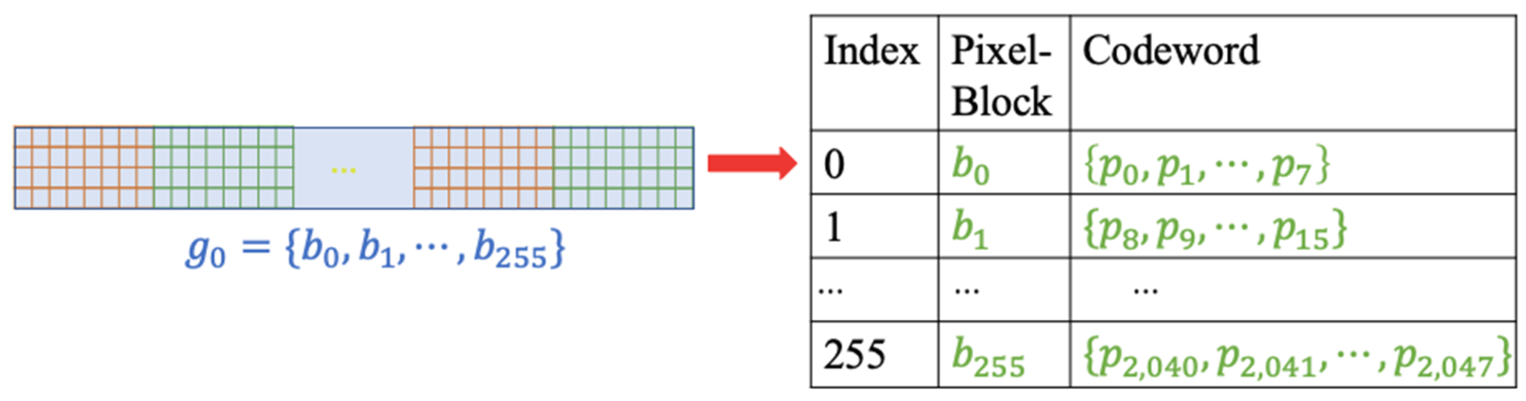
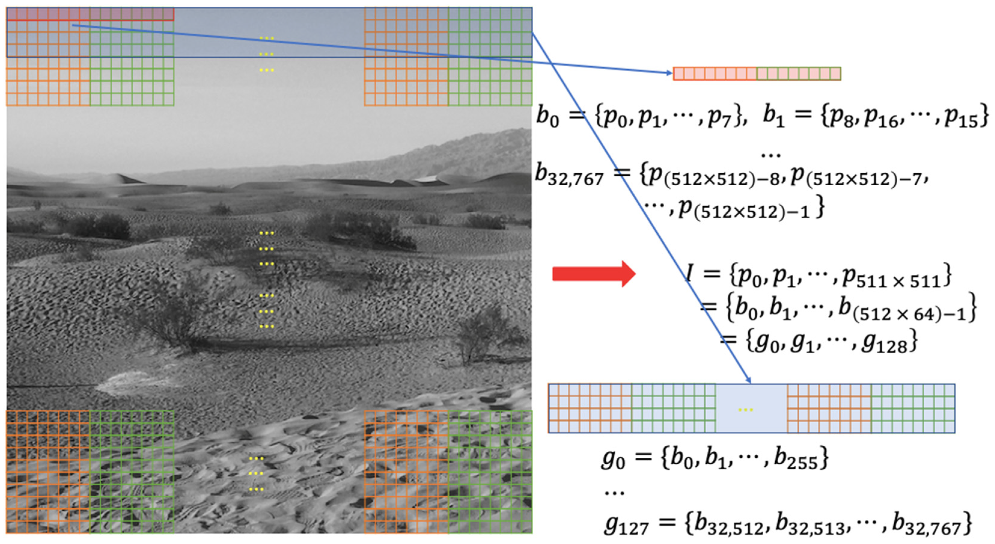
Figure 6 is an example of how pixel-blocks and block-groups are created for a
image. When a pixel-block consists of 8 pixels and a block-group combines 255 blocks, there are 32,768 pixel-blocks and 128 block-groups are formed in total for the encrypted image.
A codeword table for the block-group
of the example in
Figure 6 is illustrated in
Figure 7. The codeword table is treated as a codebook used in the codeword index reordering to hide data at a later stage.
3.3. Pixel-Block Number Embedding
Before hiding data, recording the indices of pixel-blocks in a block-group is needed for the image recovery. The original index of a pixel-block
in a block-group is calculated based on the following:
where
is the number of pixel-blocks in a block-group and
is the current pixel-block. For example, the number of pixel-block
in block-group
is 2 and the number of pixel-block
in block-group
is 1.
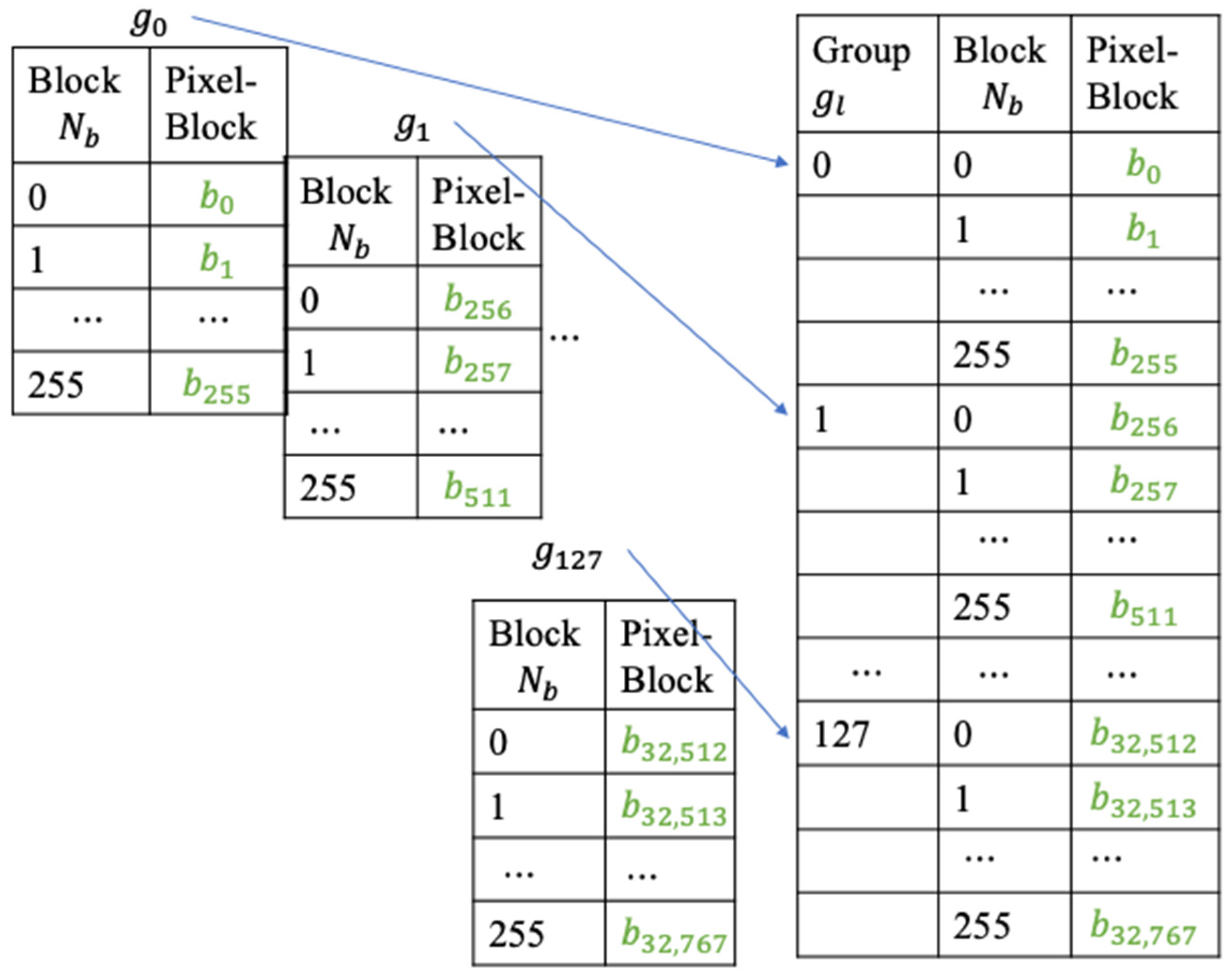
Figure 8 shows a diagram on how pixel-blocks are numbered in each block-group.
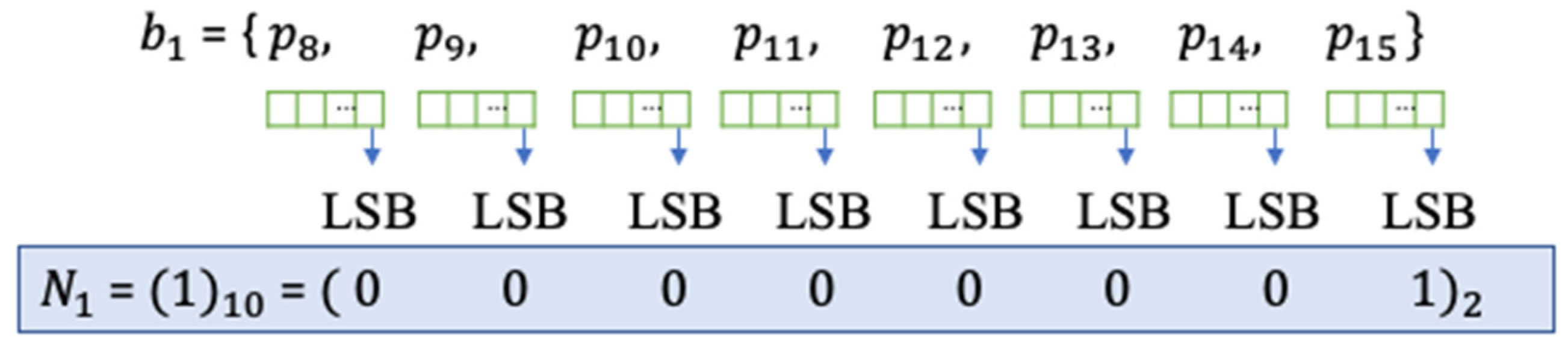
Since there are
pixels in a pixel-block, the least significant bit (LSB) [
5] of each pixel in the block is used to indicate its pixel-block number in a block-group.
Figure 9 demonstrates how to embed a calculated block number
to LSBs. The LSB bit in each pixel inside of a pixel-block is replaced with the binary bit value of its calculated block number in its group. The example shows the decimal value of 1 which is the calculated block number for
in
.
After embedding the calculated block numbers as metadata into the LSBs, the encrypted image is now an encrypted image embedded with image recovery information. It is then sent to the data hider to hide secret data.
3.4. Data Hiding
When the data hider receives the encrypted image
with embedded block numbers, a data hiding key
, and a secret message
, an n-dimensional line
is generated according to the data hiding key
. The pixels in each pixel-block form a codeword and obtain a projected value by projecting the codeword to the line
. A codeword table
is created for each block-group by using these codewords and is sorted by their projected values. The sorted codeword table
is then used to embed the secret bits by applying the codeword index reordering technique described in
Section 2.2.
Algorithm 1 details the steps of how to embed the secret message
:
| Algorithm 1: Data Hiding. |
| Input | The encrypted image , the pixel-block size , the block-group size , the data hiding key , and the secret message . |
| Output | A marked image . |
| 1: | Obtain an n-dimensional line for pixel-blocks in a block-group to project to by using the data hiding key |
| 2: | Initialize a marked image . |
| 3: | Form pixel-blocks and block-groups based on sizes and . |
| 4: | FOR each block-group in the encrypted image |
| 5: | Generate a codeword table using |
| 6: | Initialize projected values PV = {} |
| 7: | FOR each pixel-block in
Obtain projected value
Append to PV.
END |
| 8: | Sort codeword table T according to PV to obtain the sorted codeword table . |
| 9: | Initialize a stego codeword table ST = {}. |
| 10: | WHILE SM is not empty and is not empty
Calculate the number of secret bits that can be embedded by using
Convert secret bits to a decimal index
.
Move codeword out from and add to .
END |
| 11: | FOR each codeword in
Append to the marked image .
END |
| | END |
| 12: | Export . |
3.5. Data Extraction and Image Recovery
After receiving the marked image , the secret message can be extracted when a receiver has the data hiding key . When a receiver has the encryption key , a recovered image with high visual quality can be obtained. If a receiver has both keys, the secret message can be extracted and the recovered image can be obtained.
3.5.1. Data Extraction
If a receiver has a data hiding key
, the secret data can be extracted. The marked image
is converted into a pixel stream first. Depending on the size of a pixel-block
and the number of blocks
in a block-group received, it is divided into pixel-blocks and block-groups first. A n-dimensional line
is generated by using the data hiding key
. The pixels in each pixel-block form a codeword and obtain a projected value by projecting the codeword to the line
. A codeword table
is created for each block-group of the marked image by using these codewords and is sorted by their projected values. Both the sorted codeword table
and the codeword table
created from the marked image are used to extract the secret data. The detailed steps are provided in Algorithm 2.
| Algorithm 2: Data Extraction. |
| Input | The marked image , the size of pixel-block , the size of block-group , and the data hiding key . |
| Output | A recovered secret message . |
| 1: | Obtain the n-dimensional line for pixel-blocks in a block-group to project to by using data hiding key . |
| 2: | Initialize the recovered secret message . |
| 3: | Form pixel-blocks and block-groups based on sizes and . |
| 4: | FOR each block-group in the marked image |
| 5: | Generate a codeword table using . |
| 6: | Initialize projected values PV = {}. |
| 7: | FOR each pixel-block in
Obtain projected value
Append to PV.
END |
| 8: | Sort codeword table T according to PV to obtain the sorted codeword table . |
| 9: | FOR each codeword in the codeword table
Find the index of in and remove from .
Convert decimal index to binary secret bits
= .
Append secret bits to .
END |
| | END |
| 10: | Export . |
3.5.2. Image Recovery
If a receiver has an encryption key
, a recovered image with high visual quality can be obtained. The marked image
is converted into a pixel stream first. Depending on the size of a pixel-block
and the number of blocks
in a block-group received, the marked pixel stream is broken into pixel-blocks and block-groups. The pixels in each pixel-block form a codeword, and a codeword table
is created for each block-group of the marked image by using these codewords. We can extract the original pixel-blocks’ indices by extracting the values from the LSBs of pixels in pixel-blocks and recover the pixel values by using the encryption key
. Algorithm 3 goes through the recovery steps in more detail.
| Algorithm 3: Image Recovery. |
| Input | The marked image , the size of pixel-block , the size of block-group , and the encryption key . |
| Output | A recovered image . |
| 1: | Initialize the recovered image . |
| 2: | Form pixel-blocks and block-groups based on sizes and . |
| 3: | FOR each block-group in the marked image |
| 5: | Generate a codeword table using . |
| 6: | Initialize block values BV = {}. |
| 7: | FOR each pixel-block in
Obtain block value b from the LSB of each pixel in .
Convert b to decimal .
Append to BV.
END |
| 8: | Sort codeword table T according to PV to obtain the sorted codeword table . |
| 9: | FOR each codeword in the codeword table
Append to .
END |
| | END |
| | Recover image by using encryption key to decrypt image with bit XOR operations. |
| 10: | Export . |
4. Experimental Results
In this section, we conducted experiments on an Intel(R) Core(TM) i5-9500 CPU utilizing the MATLAB environment, version 2017a, within the Windows PC operating system, in order to assess the performance of the proposed solution and compare it with some state-of-the-art (SOTA) schemes.
We evaluated the performance of the proposed data hiding scheme through experimental analysis. A binary data stream
, generated by a random number generator, was employed as the secret information. The two key factors that we pay attention during data hiding are good visual quality and high embedding quantity. To keep the visual quality means that the recovered images look as similar to the original cover images as possible. To efficiently measure the embedding quantity, embedding capacity (EC) is calculated, representing the total number of bits that the proposed scheme could embed in the image. With the evolution of data hiding techniques, numerous metrics have been utilized to assess the visual quality of the restored images. The commonly employed metrics include Peak Signal-to-Noise Ratio (PSNR) and Structural Similarity Index (SSIM). The calculation formulas are provided below:
where
and
represent the width and height of the images, and
and
denote the pixel values at position
for the cover image and the restored image.
represents the mean value used as an estimate for luminance;
is the standard deviation used as an estimate of contrast;
denotes the covariance between the original image
and the restored image
and serves as a metric for structural similarity;
, and
are two constants close to zero.
A higher PSNR value indicates less distortion caused by the hidden data. Typically, PSNR values exceeding 30 dB suggest image distortion imperceptible to the human eye. SSIM combines three factors—luminance, contrast, and structure—to assess the similarity between two images. The SSIM range is from −1 to 1. As the value of SSIM approaches 1, it demonstrates a higher degree of similarity between the two images.
At the same time, information entropy is selected to test the security of the encrypted image, that is, the randomness of the image histogram is calculated by the following method:
where
represents the image pixel value between 0 and 255, and
is the probability of the image pixel value
occurring. An information entropy value closer to 8 means that the encrypted image has higher randomness.
In
Section 4.1, we evaluate the performance of our proposed scheme under different test images. We give some execution results and security analysis in
Section 4.2.
Section 4.3 gives comparisons with other SOTA schemes.
4.1. Performances of Our Proposed Scheme
The embedding capacity of the proposed scheme is contingent upon the pixel-block size and the codeword table size. Therefore, we initially conducted performance tests on different test images by varying the pixel-block sizes in a codeword table. The group size in
Table 1 and
Table 2 is what we call the codebook table size.
Table 1 lists the results of applying the proposed scheme to the test images for different pixel-block size configurations with the same codebook table size. We observed that when pixel-blocks have an identical number of pixels, the shapes of the pixel-blocks had no effect at all on EC values depicted in
Table 1; the shapes also had no significant impact on PSNR and SSIM. Therefore, we could simplify our scheme by converting the encrypted images to a pixel stream first and specifying the size of a pixel-block without the necessity of specifying the width and the height of a pixel-block. However, the number of pixels within a pixel-block had a significant effect on EC, and the larger the size of the pixel-block, the less EC the proposed scheme could provide. Moreover, the larger the pixel-block, the higher the PSNR and SSIM values of the recovered image when the size of the codebook table was the same. Simultaneously, we observed that the most efficient partitioning is to have
pixel-blocks within a block-group when the size of a pixel-block is n.
In addition to these metrics, we also employed the number of pixels changing rate (NPCR), unified average changed intensity (UACI), and mean absolute error (MAE) to evaluate image distortion between the original and the restored images. The calculation formulas for these metrics are as follows:
where
and
represent the width and height of the images, and
and
denote the pixel values at position
for the cover image and the restored image.
NPCR is employed to compute the number of differing pixels between two images, while UACI is utilized to calculate the average change in pixels between two images. Unlike
Table 1,
Table 2 is a test of the proposed scheme with various codebook table sizes. From
Table 2, it can be clearly seen that as the size of the codebook table becomes larger, the EC of the proposed scheme also becomes larger. Since the efficient pairing of codebook table size and pixel-block size was utilized, the LSB of each pixel in a pixel-block was used to record the original pixel-block index in a group, and the PSNR values of all tested scenarios were around 51 dB. The PSNR values indicated that our recovered image had a good visual quality. As shown in
Table 2, the proposed scheme involves replacing the LSB of pixels with the initial block index in a group after encrypting the image. Consequently, after extracting information and decrypting the image, the LSB of each pixel cannot be fully restored, with a 50% probability of being flipped. As a result, NPCR values are around 50% across various test images. UACI values are notably low, with the highest UACI not exceeding 0.2%, indicating that the average pixel changes induced by the proposed scheme are small, even if the images cannot be fully recovered. Mean Absolute Error (MAE) is also an indicator for assessing image quality, where a smaller MAE value corresponds to better image quality. From
Table 2, we can see that the MAE values are small for all images. In summary, the proposed scheme causes very little damage to the cover images when embedding the secret data and the recovered images are very similar to the cover images.
4.2. Execution Results and Security Analysis
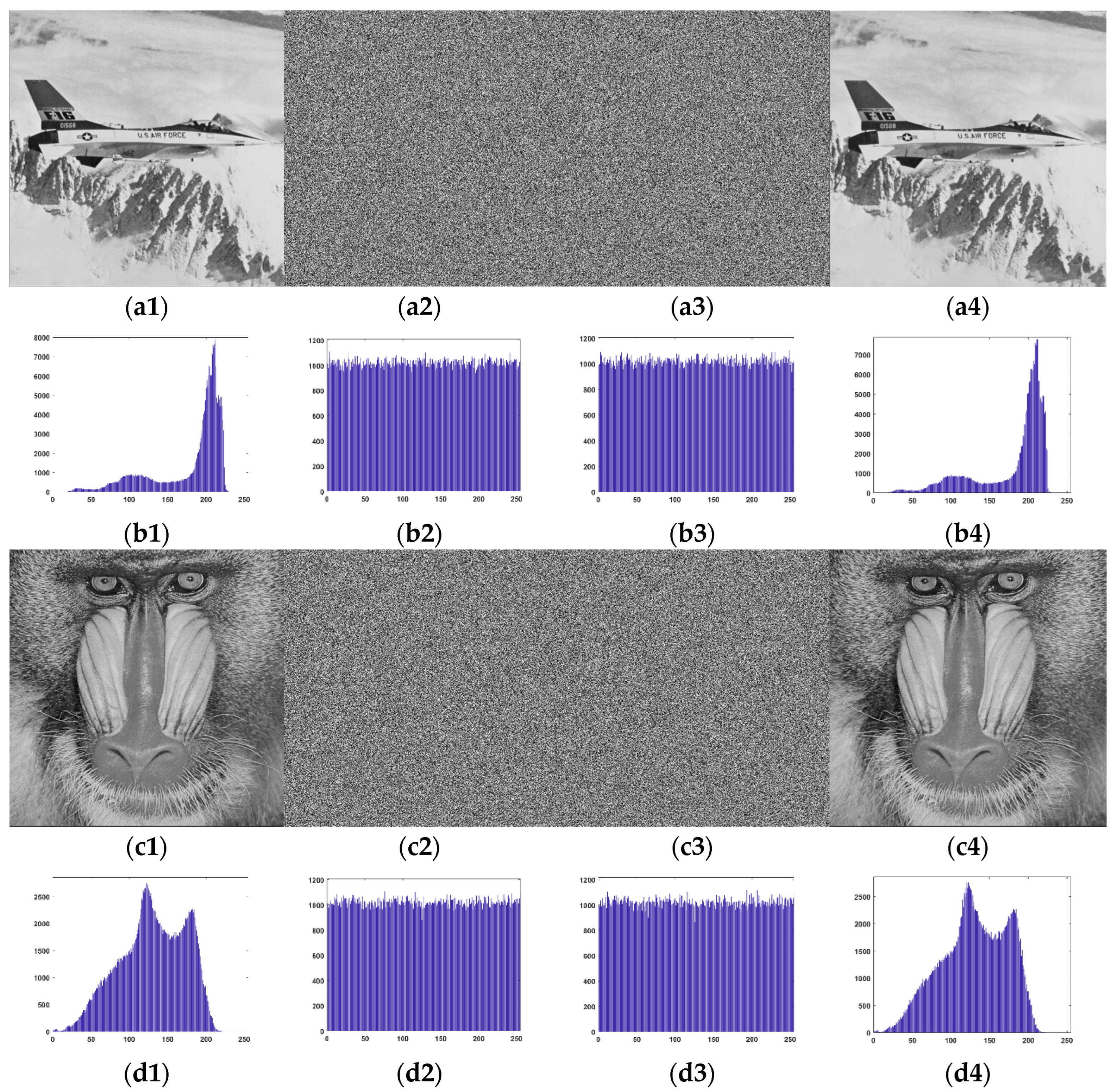
Figure 10 presents the performance results of various test images at different stages. After image encryption, pixel values become disordered, rendering meaningful information indiscernible, and the pixel distribution in the histogram of the encrypted image is consequently uniform. Since our proposed data embedding scheme involves merely scrambling the positions of encrypted pixels after recording the original block indices using LSB replacements, the distribution of pixel values in the encrypted image does not undergo substantial changes. The histogram distributions of the recovered images that we are able to obtain after extracting the information are also very similar to the original histogram distributions.
In addition to information entropy, another way to analyze the differences between adjacent pixels is to use the correlation coefficient to assess the correlation between adjacent pixels. A natural image has a high correlation between neighboring pixels normally, but for a secure encrypted image, the lower the correlation between its neighboring pixels, the more secure it is. It is defined as follows:
We divide the image into pixel pairs, take the former of all pixel pairs as
and the latter of all pixel pairs as
, with
denoting the number of pixel pairs, and then calculate the correlation coefficient between them.
Table 3,
Table 4 and
Table 5 were tested with a pixel-block size of 8 and a codebook table size of 256. The information entropy and the pixel correlation results for horizontal and vertical pairs are shown in
Table 3 and
Table 4, respectively.
Table 3 provides measurements for the original, encrypted, and embedded encrypted images of different test images. Clearly, the entropy values for the encrypted and embedded encrypted images of each image are quite similar, as our proposed scheme only employs one-bit LSB replacement on encrypted pixels and subsequently scrambles the pixel positions. On the other hand, the entropy values for different encrypted images are consistently close to 8, significantly higher than the entropy values of the original images. Consequently, the distribution of pixel values in encrypted images exhibits heightened randomness, thereby enhancing security.
As shown in
Table 4, neighboring pixel values in the original image have strong positive correlation both horizontally and vertically, while the pixels of encrypted and marked images have only very low correlation both horizontally and vertically. Also, the correlation between the marked image and the encrypted image does not change much compared to the encrypted image both horizontally and vertically. This indicates that the Stream Cipher encryption completely encrypts the image, and the proposed scheme that utilizes the reordering of the codebook table to embed the secret data inherits this feature and does not make the correlation between the pixels higher due to the embedded data.
The security of the proposed scheme is further analyzed in
Table 5 using two metrics, NPCR and UACI. The definition and computation of both NPCR and UACI have been mentioned in
Section 4.1. In terms of security analysis, the higher the NPCR value, the more effective the encryption algorithm is, because the higher the number of different pixels, the harder the encrypted image is to crack. For two uncorrelated images, the theoretical value of UACI is 33.33%. As shown in
Table 5, for both encrypted and marked images, the NPCR value and UACI value of the proposed scheme are close to the theoretical optimal value, which indicates that our scheme can provide a high level of security against potential attacks.
Table 6 shows the time in seconds spent by different stages of the proposed scheme on different test images. The pixel-block size of the proposed scheme is 8, the codebook size is 256, and 197,888 bits of secret data are embedded. From the table, we can see that the proposed scheme spends 6.30 s in the embedding stage at most, and 2.85 s in the extraction and recovering stage at most. Overall, the cost of time spent is acceptable.
4.3. Comparison with State-of-the-Art Schemes
In this section, we primarily compare our proposed scheme with some state-of-the-art schemes for data hiding in encrypted images in terms of PSNR, SSIM, and embedding capacity. In
Table 7, it can be seen that the embedding capabilities of our proposed schemes outperform all the other schemes. Moreover, our proposed scheme consistently provides stable embedding capacity for any image, as long as the pixel-block size and the number of blocks within a group remain unchanged. The independence of embedding capacity from image content is attributed to our utilization of indices within each group for data embedding. So, as long as the number of blocks in the group and the size of the pixel-blocks are consistent, images of the same size will have the same embedding capacity. From
Table 7, it is evident that our proposed scheme also outperforms most SOTA methods based on the PSNR values and SSIM values. Even though the PSNR is slightly lower than [
17], our proposed scheme achieves a PSNR of approximately 51 dB, which is adequate for visual quality of a recovered image.
In
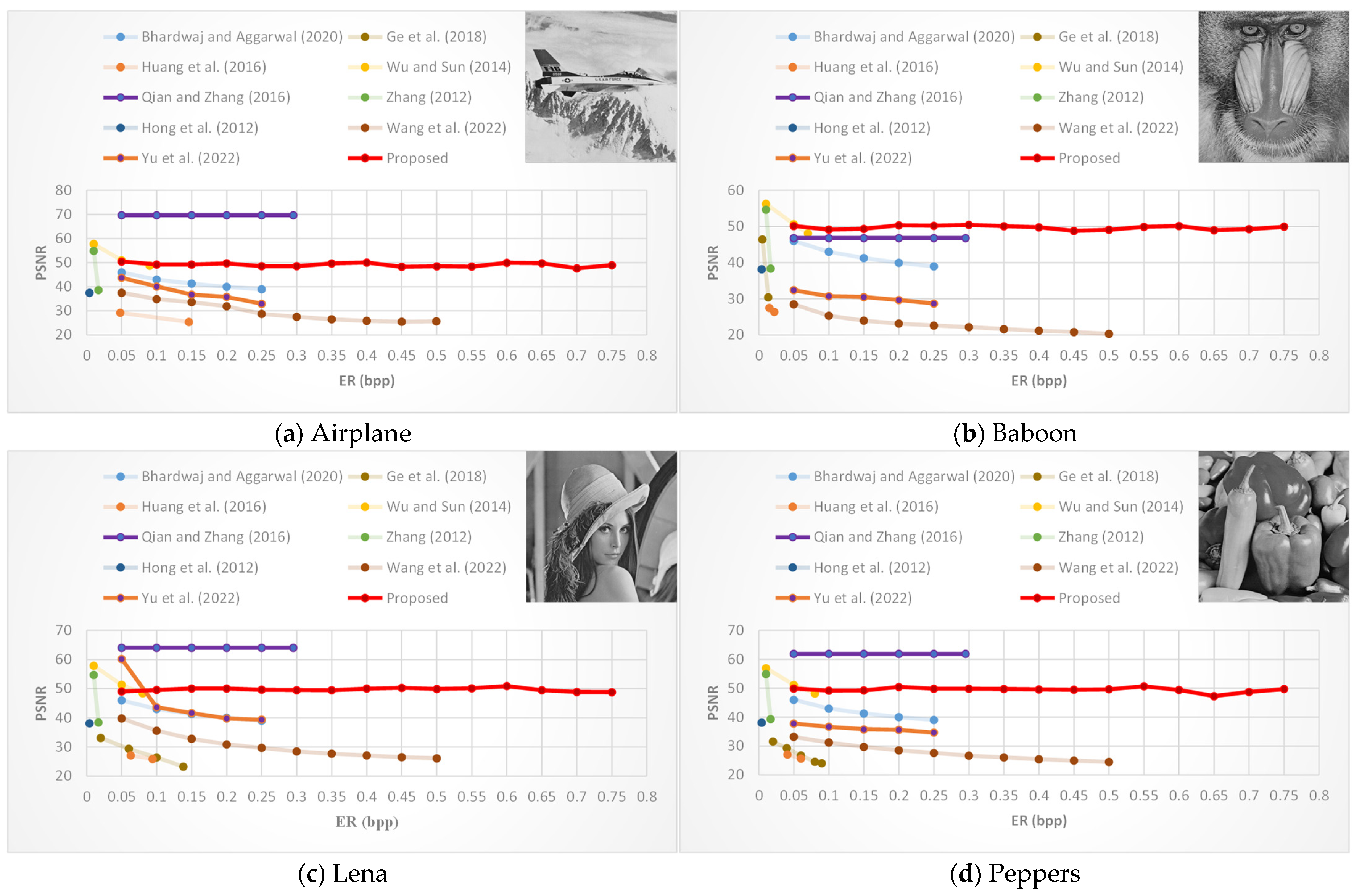
Figure 11, we further compare the PSNR of our scheme with more SOTA schemes under different embedding capacities, with a pixel-block size of 8 and 256 blocks within a codeword table. In
Figure 11, we use the embedding ratio (ER) to represent the embedding capacity (ER = EC/total number of pixels). As depicted in
Figure 11, in most cases, the PSNR values of other schemes tends to decrease with increasing embedding capacity. In contrast, our proposed scheme consistently has a stable PSNR for the recovered image. Therefore, as the amount of embedded secret data increases, the advantages of our proposed scheme become more pronounced in terms of the PSNR and the SSIM of the recovered image. As long as the embedding rate is greater than 0.25 bpp, the proposed scheme has better visual quality and higher embedding capability than other schemes.
5. Conclusions
In the proposed scheme, a content owner encrypts an image first using the Stream Cipher technique with an encryption key and embedding pixel-block numbers in each block-group by replacing LSBs of pixels in each pixel-block. The encrypted image with embedding pixel-block numbers is then sent to a data hider to embed a secret message and create a marked image using a data hiding key and the codeword table index reordering technique. The marked image is sent to the receivers. When a receiver has the data hiding key, the secret message can be extracted. When a receiver has the encrypted key, the image can be reconstructed with minor distortions because of LSB replacements.
With our experiment results, we are confident that the proposed scheme could achieve our goal of increasing embedding capacity by a significant amount compared to the SOTA schemes. Our experiments showed that the embedding capability with any cover image is consistent as long as the sizes of pixel-blocks and block-groups were the same. As for PSNRs, the results showed that the proposed scheme could outperform the SOTA schemes as well. Because of LSB replacements, our scheme has a limitation in that the images are not fully recovered, yet the PSNR reaches 50 dB, which indicates that the images have good visual performance.


