Article

Internet of Robotic Things (IoRT) and Metaheuristic Optimization Techniques Applied for Wheel-Legged Robot

by
Mateusz Malarczyk
1,
Grzegorz Kaczmarczyk
1,
Jaroslaw Szrek
2 and
Marcin Kaminski
1,*
1
Department of Electrical Machines, Drives and Measurements, Faculty of Electrical Engineering, Wroclaw University of Science and Technology, Smoluchowskiego 19, 50-372 Wroclaw, Poland
2
Department of Fundamentals of Machine Design and Mechatronic Systems, Faculty of Mechanical Engineering, Wroclaw University of Science and Technology, Lukasiewicza 7/9, 50-372 Wroclaw, Poland
*
Author to whom correspondence should be addressed.
Future Internet 2023, 15(9), 303; https://doi.org/10.3390/fi15090303
Submission received: 29 June 2023 / Revised: 29 August 2023 / Accepted: 30 August 2023 / Published: 6 September 2023
(This article belongs to the Special Issue Internet of Things (IoT) for Smart Living and Public Health)

Abstract

:
This paper presents the operation of a remotely controlled, wheel-legged robot. The developed Wi-Fi connection framework is established on a popular ARM microcontroller board. The implementation provides a low-cost solution that is in congruence with the newest industrial standards. Additionally, the problem of limb structure and motor speed control is solved. The design process of the mechanical structure is enhanced by a nature-inspired metaheuristic optimization algorithm. An FOC-based BLDC motor speed control strategy is selected to guarantee dynamic operation of the drive. The paper provides both the theoretical considerations and the obtained prototype experimental results.

1. Introduction

Robotic platforms are becoming very popular tools in industry and delivery companies. These systems are reliable and cost effective, and, additionally, movement in narrow aisles can be achieved. The maneuverability of the robotic platforms exceeds the possibilities of standard forklifts [1]. They can be used in smart warehouses, and, in such completely automated areas, aisles are designed for use of the specialized robots only. The robots are connected into a robotic network according to the idea of the Internet of Robotic Things (IoRT) [2]. This provides the possibility of remote data gathering and synchronisation of each individual object to allow autonomous operation. In the ideal world, the construction of smart warehouses (with robotic devices) may be considered as a great solution to reduce the number of employees and wasted space (that can be used for profitable production or other purposes) [3]. Coordinating the work of a smart warehouse in fully autonomous mode requires much computational power. It is crucial to process the control algorithm in real time. That is why the control system must be realized with the idea of embedded computing and the Internet of Things at once. Unfortunately, the operation of such systems may be easily disrupted. Because of narrow aisles, bypassing any obstacles, such as immobilized platforms (e.g., because of discharged batteries or faults) or scattered/unexpected objects (e.g., fallen products), may be impossible. Stopping operations may cause delays in object (that can be a part of larger system) work, which as a result may lead to financial loss. The risk of such undesired maintenance standstill may be reduced with the implementation of robotic platforms that can traverse over the obstacles. These robotic platforms may be considered a part of smart mobility. In fact, they are designed to work without the need for human control, which makes them an interesting solution in many areas of people’s lives. Smart transportation may be the answer to many dangerous or damaging jobs. The idea of autonomous robots provides the possibility of building more advanced robot constructions, which may be capable of carrying out more complicated tasks than traditional robots. In this case, a solution could be robots with a special suspension design. Because of the similarity to the movement of animals living in nature, the suspensions of these robots are commonly called legs [4]. Legged robots can travel in three-dimensional environments, and are able to step over obstacles, climb over stairs, etc. [5]. However, they are relatively slow in good, flat environments. It can be noted that the fastest legged robot is significantly slower in comparison with wheeled platforms [6]. The best solution, which keeps the advantages of wheeled robots and the abilities of legged platforms, is a combination of their construction features. The resulting wheel-legged robots are a field of research interest in notable research institutes and famous worldwide companies. Robots from ETH Zurich [7] and Boston Dynamic [8] are examples that are very popular.
Modern microcontrollers have become powerful devices that are capable of running complex algorithms. There are many devices that come with integrated wireless communication modules such as Wi-Fi, Bluetooth Classic, Bluetooth Low Energy, etc. Their price is comparable to standard industrial microcontrollers, and thus they are widely applied as a control element of electrical machines and appliances [9]. By using these devices, the idea of the Internet of Things (IoT) can be developed. The increasing number of industrial applications is related to modern software tools (for programming), reliability and low costs. They have an influence on industrial hardware, where very often the machinery is connected into networks. This allows maintenance workers to gather debugging data quickly, update configurations or simply visualize the production process, which can be carried out using SCADA (supervisory control and data acquisition)/ HMI (human–machine interface) hardware and software [10,11]. However, it should be noted that the complex structure and high prices of such systems can reduce the number of potential implementations. Moreover, nowadays, the idea of the Internet of Things becomes an inseparable part of modern control systems. When it comes to robotic constructions, there is a massive need to equip the robots with a smart control module. Modern control units may also be determined by additional requirements, e.g., shock resistance and compact size. These features involve the need to create a dedicated embedded system, which combines real-time operations with constant online access ensured by the IoT. These embedded systems may also apply artificial intelligence algorithms to gather environmental data (e.g., example neural networks for sensor signal analysis and deep learning vision systems) and for control. The solution proposed in the paper is low-cost and consists of a single module that is able to host an HMI service while controlling the operation of the machinery. If the HMI is published as an interactive website (accessible using any web browser), no additional software is required.
The design process of the complex control structures and mechanisms requires complicated calculations. In the case of geometrical synthesis, the model of the kinematic chain is rather simple. However, the solution to the problem of providing the desired operation requires a complex search of possible solutions. This can be carried out using the naive, monotonous brute force method or, as it has already been proven [12], the optimization algorithm can be applied to solve the problem more effectively. The catalogue of metaheuristic algorithms is evolving and expanding unceasingly. The swarm intelligence methods are the most popular techniques among nature-inspired metaheuristic algorithms. Their successful applications in different disciplines have already been described and published, and include:
  • Economic issues [13];
  • Design of electronic devices [14];
  • Material strength [15];
  • Optimization of electrical machines [16];
  • IT network support [17];
  • Management of power systems [18,19];
  • Medicine [20];
  • And many others.
The paper describes the design process of a wheel-legged robot. It is divided into thematically established sections that provide subsequent steps and subjects of the design. The introduction is followed by a state-of-the-art discussion. It establishes the background for the considerations presented in the next parts of the paper. At the beginning, the embedded microcontroller system is described. In this section, the chosen motors are briefly characterized and the applied control structures are also discussed. The following section provides the description of the most important mechanism of the wheel-legged robot. It puts a special focus on the novel approach of geometrical synthesis of the robot’s suspension. The requirements and the constraints for the kinematic chain are provided in this part of the manuscript. Then, the flower pollination algorithm is briefly described and its application to calculate the dimensions of the four-bar linkage suspension (to fulfill defined requirements) is described in detail. The description of the swarm intelligence-based optimization process is supported with chosen simulations results and the real prototype of the wheel-legged robot. In the same section, the second application of the FPA is also briefly presented. The speed controller used for the BLDC motors is optimized with the same algorithm that is used in the synthesis of the mechanical system. This part of the paper summarizes the speed transients achieved with the robot prototype. The next section of the article is focused on the master controller—ESP32—and the developed HMI system. This section also provides the principles of the implemented state machine and the communications between modules. The control process is realized using the developed website. Moreover, the Ackermann model is also provided. The paper is concluded with the concluding remarks and the plans for further research.

2. State-of-the-Art and Related Work

The popularity of metaheuristic algorithms is mainly based on the high efficiency and universality of these applications. The methods require less time for calculations and are memory efficient, while the obtained results are satisfactory and the computation complexity is rather low. The problem of derivative calculation is skipped in such techniques; in most applications, simple calculations (such as matrix multiplication) are needed. Thus, the number of observed implementations is increasing. This leads to subsequent improvements and modifications of existing methods. The efficiency of different approaches can be synthetically tested with benchmark functions or directly with engineering problems—[21] provides a review of the chosen algorithms, and ref. [22] provides the efficiency results and shows the popularity and development of metaheuristic algorithms (more than 500 optimizers are listed). The efficiency of metaheuristic algorithms can be also proven by checking their results in problems with defined boundaries and unconstrained tasks [23].
The issue of suspension optimization has already been examined by researchers. Different design methods and algorithms have been verified [24,25,26]. However, the flower pollination algorithm has only been applied to the control system of the gyroscope suspension [27], and it has never been applied to the mechanical task of finding the geometry of the mechanism. Thus, the approach and the research presented in this paper provide an original solution (new application of the FPA and different design method of the kinematic chain). Robotic platforms are becoming very popular tools in different fields—they can be used in warehouse and delivery tasks, and also in agriculture [28], mining [29] and general monitoring designs. The main disadvantage of most robot applications is their ability to travel only on flat surfaces, without the possibility of moving over or around obstacles. However, this issue has been noticed by researchers, and different solutions have been presented recently [30,31]. The high research popularity is based on the necessity of developing machines that can replace humans, both in hazardous environments and for repeatable, monotonous tasks.

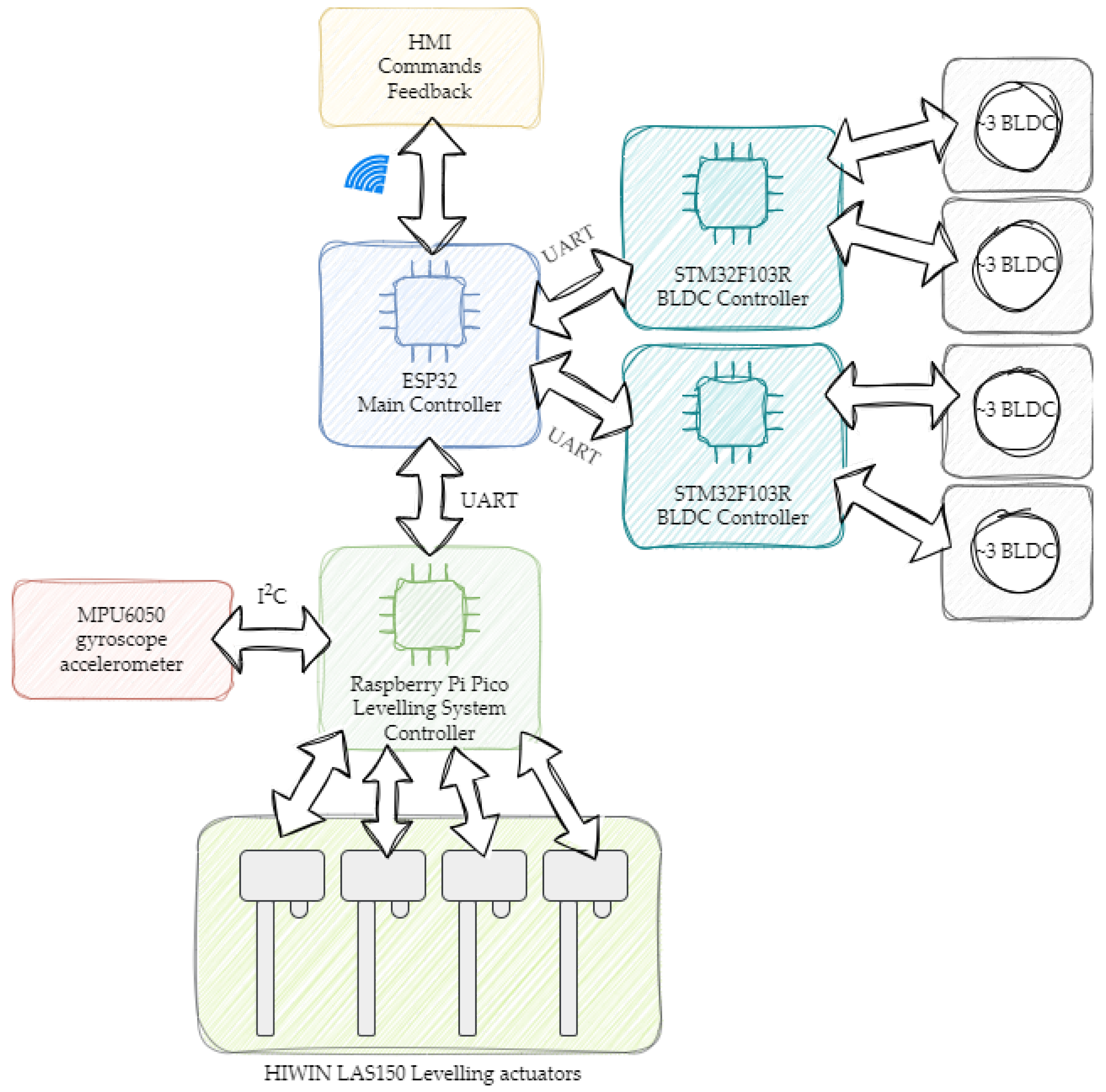
3. Description of the Control System

Over the years, in the area of autonomous devices used in industrial applications, significant developments have been observed. Robots have become an inseparable part of modern automation. A constant improvement in microprocessors and programmable systems makes robotic constructions capable of carrying out more and more computationally demanding operations. In the case of autonomous (self-driving) robots, it is not allowed to place the main control loop in the cloud control system, due to a possible connection problem or data-transfer delay, and therefore a real-time operating system should be used. Thus, sufficient computational power on board of a robot chassis is required. This is possible using edge computing systems (e.g., NVIDIA Jetson modules). On the other hand, the application of these processing units is strongly governed by their high price. Additionally, to fulfill the requirements of modern industry, controllers with wireless connection protocols on board should be applied. In this project, an ESP32 module has been used.
The ESP32 board is a low-cost microcontroller system developed by Espressif Systems. When comparing this module with other popular development boards (e.g., Nucleo), the communication possibilities should be emphasized. It is considered as a microcontroller dedicated to Internet of Things applications. Not only does the ESP32 contain Wi-Fi and Bluetooth modules, but it also integrates some basic sensors on board (e.g., Hall sensor and touch sensor). The main unit of the board is powered by a dual-core Tensilica microprocessor (240 MHz). In addition to the typical GPIO pins used for connections, it also provides an analog-to-digital converter (12 channels) and DAC (2 channels). Additional details of the specifications are presented in Table 1. Considering the advantages of this device, it seems a perfect solution for a low-cost main control unit in a developed construction. The ESP32, combined with popular microcontroller units (e.g., STM32 boards), creates a powerful control system capable of running advanced applications in real time, which makes it a perfect tool for autonomously driving robots.
The whole control system consisted of different microcontrollers. All of them worked in a master–slave system. The main microcontroller ensured the wireless connection with the robot, transferred the (read) data to the control web page and received proper instructions sent by the user. The main task was focused on calculations of inverse kinematics, which was obligatory to receive the information on which drive should be activated in a specific moment (with a proper reference speed in order to move the robot in desired direction). It was also responsible for collecting data from sensors. The control system was divided into two subsections: the first one was responsible for motion control of the robot, while the second one controlled the leveling system of the chassis. Each of them received the control commands from the master device (ESP32 module). The structure of the control system is shown in Figure 1.
The first part of the control structure was responsible for motion control of the robot. The whole drive module was divided into two parts. The first one controlled the front axle drives, while the second one was responsible for the rear axle. Each of them was equipped with two independent in-wheel BLDC motors. For each axle, a dedicated BLDC controller was designed. The control algorithm was implemented in the STM32F103R microcontroller. The BLDC control module, in the form of an independent board, contained both power and control modules. Different ways to control a BLDC motor have been described in the literature [32]. In the case of brushless motors, it is demanded to ensure a correct phase switching sequence instead of delivering a proper voltage to its terminals [33]. To ensure correct operation, an electronic commutator is required (usually in the form of a 3-phase inverter module). The control method of a BLDC motor is strongly dependent on the shape of the back electromotive force induced on the unused phase. In the case of a trapezoidal shape, the input signals generated thorough Hall sensors are used to specify the current rotor position. Based on the received information, a specific pair of transistors in a closely determined time window is switched. In the case of a sinusoidal shape of the back-EMF, an FOC control structure is often implemented [34].
The main idea of FOC (field-oriented control) is to control the stator current components related to the rotor flux. Because of the given structure, it is possible to ensure full torque control in dynamic states of the electric drive. This feature is essential in robotics. Analyzing the placement of vectors shown in Figure 2, the stator current vector ( i s ) can be divided into two components. The first one ( i s d ) is related to the flux, while the second one influences the actual torque value (generated inside the motor). In the brushless motor, the flux is generated by the set of permanent magnets placed on the rotor surface. Thus, the i s d current component needs to equal zero. The second component ( i s q ) corresponds to the stator current vector and affects its value directly. Increasing the i s q component value is forced to keep the torque at a desired level. The adjustment depends on the operation stage of the machine and the actual torque load.
One of the main advantages of the application of the field-oriented control method is the similarity to the cascade control of a conventional DC motor. The separate path for the electromagnetic torque, m e , control is noticed. It is related to the mathematical equations describing the value of the signal:
m e = Ψ w · i t = c o n s t · i t ,
m e = Ψ P M · i q = c o n s t · i q .
Two main control paths may be distinguished in the FOC structure. The first one consists of two PI controllers (Figure 3). The first one is related to the main state variable, and processes the speed error and generates the reference value for internal part of the system [35,36,37]. The analyzed controller calculates the i s q component corresponding the torque value. The second path contains a controller that forces the i s d component to zero. The speed above the nominal value may be obtained by decreasing the i s d component to below zero. For BLDC motors, the flux angle, required to make a proper Park’s transformation, corresponds to the rotor position directly [38]. The final output signals from the current controllers are used after recalculation of the inverse Park transformation block. Obtained signals are provided to the space vector modulation (SVM) unit, which controls the transistors in the power module. In the proposed construction of the robot, the FOC has been implemented in STM32F103R.
The second part of the main system was responsible for control of the chassis level. The algorithm was implemented in Raspberry Pi Pico, which is a powerful development board based on a dual-core ARM Cortex M0+ chip. This unit is equipped with a variety of communication protocols (e.g., 2xSPI, 2xI2C and 2xUART) and 26 GPIO pins. Moreover, Raspberry Pi Pico gives a wide range of advanced peripheral extensions, which are perfectly suitable for creating a drive system (e.g., ADCs and PWM generator). The advantage of the Raspberry Pico over other popular microcontrollers is related to easy accessibility and uncomplicated software. The software may be developed using Arduino IDE. Additionally, the embedded code can be directly written in both C and Python programming languages [39].
The Raspberry Pi Pico unit acquired the data from the MPU6050 sensor. The device was equipped with an on-board gyroscope and accelerometer, and provided information to control the chassis level. The communication between devices was realized using an I2C protocol. The microcontroller used the implemented position control structure to generate four independent PWM signals, connected directly to dedicated power modules (based on a typical H-bridge power electronic structure). The DC motors were coupled directly to the linear actuators that were responsible for the position of the suspension.
A standard cascade control structure is a reasonable and efficient method to control the speed of a DC motor [40]. The PI speed controller generates the input value for the inner current control loop (equipped with the PI controller) [41]. The position control structure is extended with one additional PI controller. The output of the additional controller is the reference speed value. The output is computed based on the position error, defined as the difference between the reference and measured values [42,43]. The speed and position in the analyzed control system was measured using four incremental encoders connected to the Raspberry Pi Pico microcontroller. The implemented position control algorithm is shown in Figure 4.
The comparison of microcontrollers used in the hardware construction of the robot analyzed in the article is shown in Table 1.
Table 1. The specifications of the programmable devices used in the project, compiled based on refs. [44,45,46].
DeviceRaspberry Pi PicoSTM32F103RESP32
Power consumption<1 W<1 W 5 W
CoreRaspberry RP2040 ARM Cortex M0+ARM Cortex MDual-Core Tensilica LX6
Clock rate133 MHz72 MHz240 MHz
User memory size2 MB64 kB4 MB
RAM264 kB20 kB520 kB

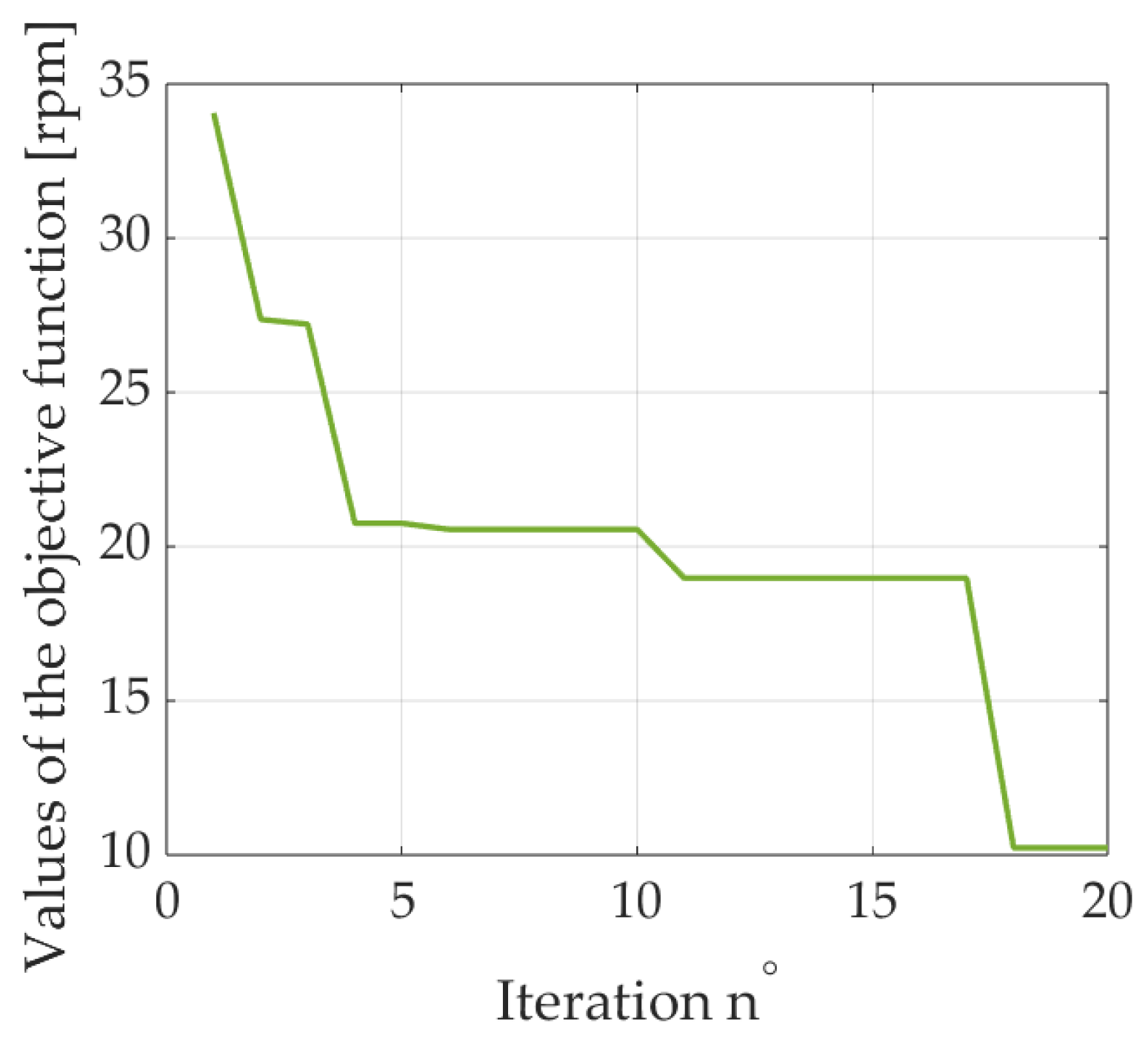
4. Geometrical Synthesis with Flower Pollination Algorithm

The kinematic chain structure was chosen during structural synthesis based on the below defined requirements and presumptions.
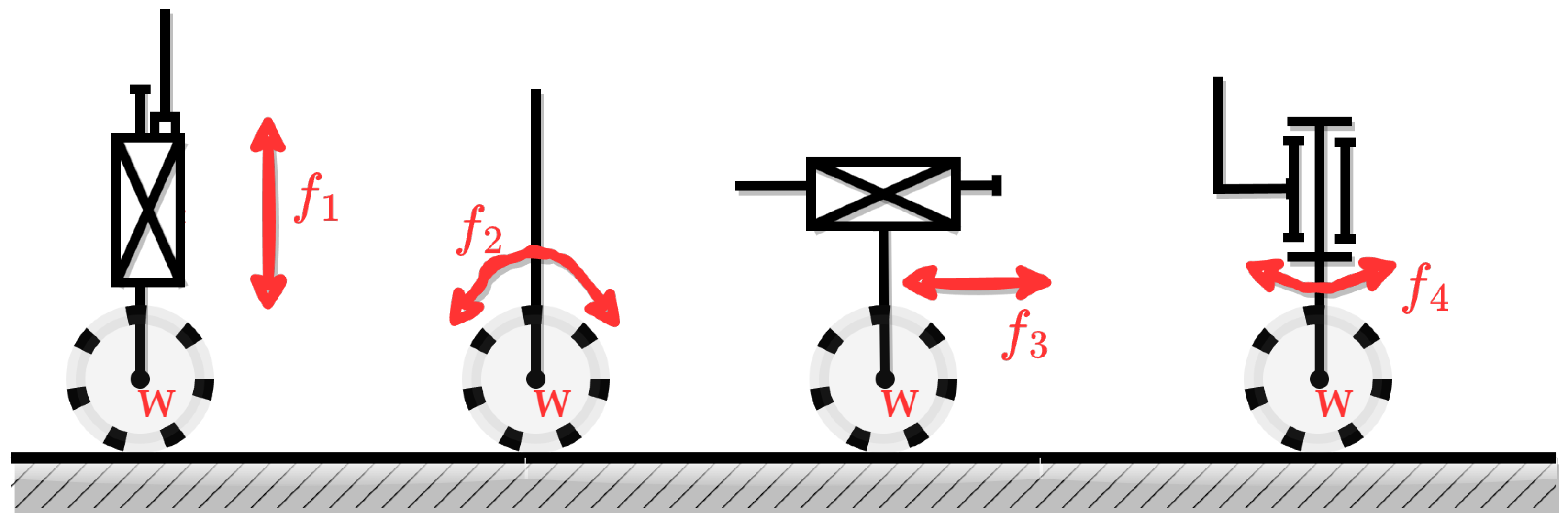
  • Drives should be installed on the platform directly (to reduce mass of the elements attached to the structure).
  • The mechanism should allow to follow the desired trajectory with a single drive only.
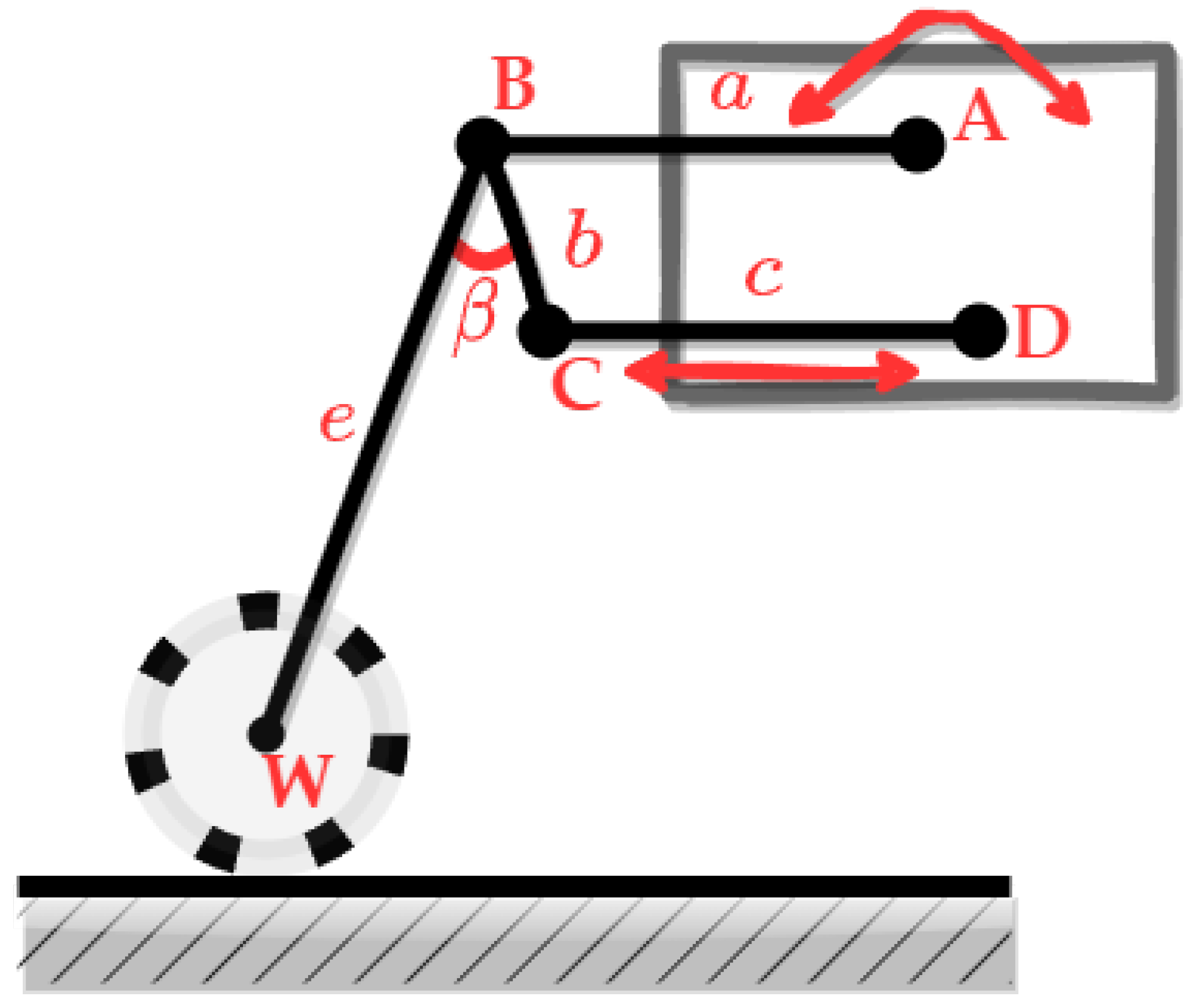
  • The total number of freedom degrees of a single mechanism equals 4 (Figure 5). For synthesis purposes, this can be reduced to 3 as the driving motor introduces the f 2 independently to the suspension mechanism. It can also be noted that turning can be obtained with a simple gear attached at a fixing point of the BLDC motor. Taking these assumptions into consideration, only two degrees of freedom have to be reproduced with a suspension kinematic chain.
  • Both translational and rotational joints can be used.
Figure 5. Required degrees of freedom.
Futureinternet 15 00303 g005
A four-bar ABCD linkage mechanism was selected as the base of the construction (Figure 6). The simple structure was chosen because of two fixing points placed directly on the platform chassis. Both of the mentioned points were also the propulsive elements—the rotational joint (in point A) was responsible for level, and the translational joint (between points C and D—second fixing point) was designed to performs several steps of the robot. After selection of the fixing points, the heavy drives were attached to the chassis. Therefore, the inertia of the mechanism was reduced.
The AB rocker (a crank) was considered as a constant length element, while the CD bar (a follower) was designed with an adjustable length. Such ability, as well as high torque and easy control, were provided through a linear actuator. If the required position is obtained, the drive can be switched off, which leads to low power consumption. The in-wheel BLDC motor was combined with an e element (in point W), connected to a four-bar mechanism (in point B) and oriented with BC linkage (a coupler). The geometry was defined; however, the exact lengths of the elements were required to assure appropriate operation. The following conditions were assumed for the construction:
  • A linear trajectory, perpendicular to ground level;
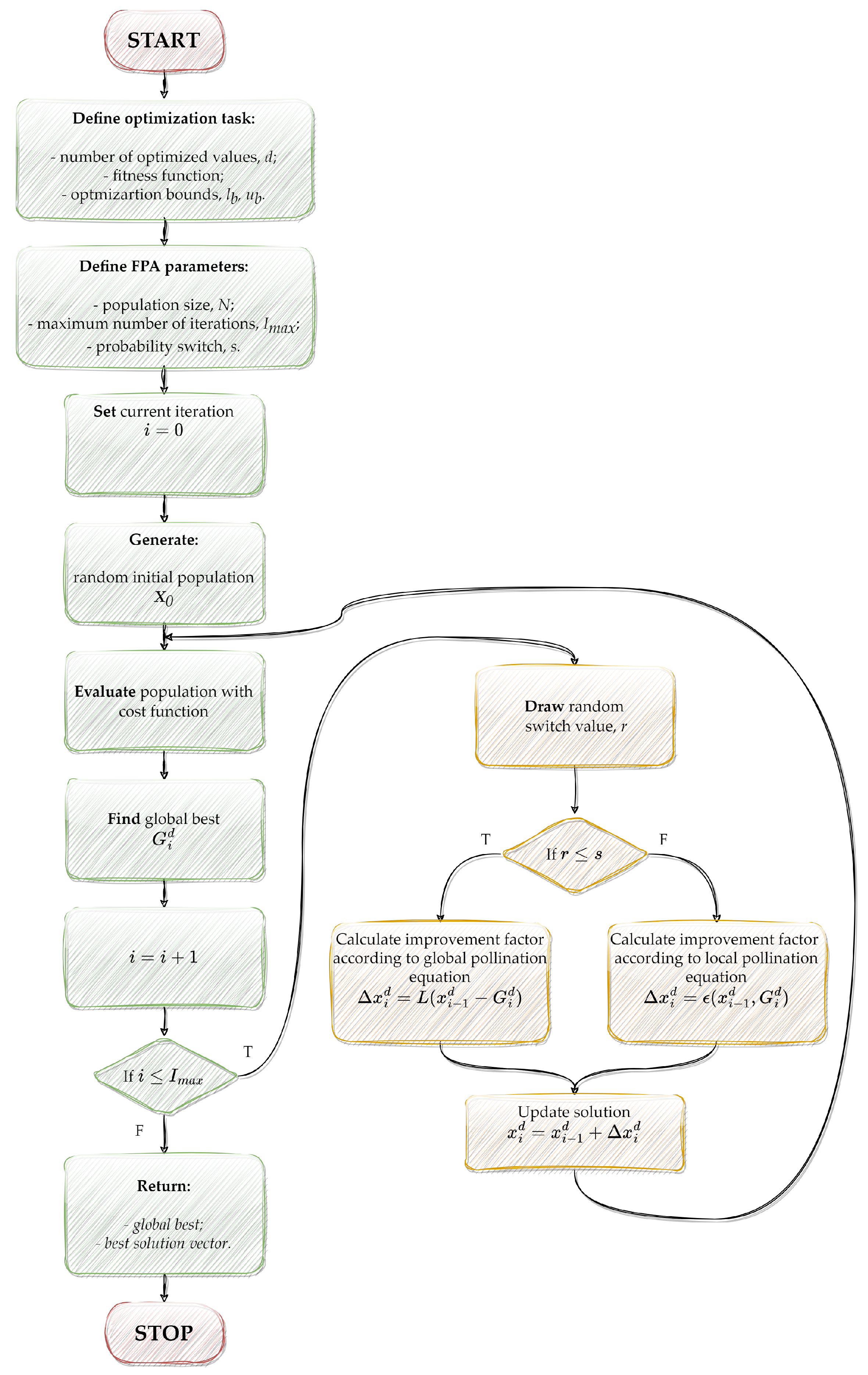
  • Movement along the desired trajectory proportional to the controlled angle (in joint A).
    The above issue is related to the geometrical synthesis task. Different approaches may be used to solve the problem. In the presented work, the flower pollination algorithm (FPA) was used to find the optimal configuration of the kinematic chain lengths. The method was firstly described by Xin She-Yang [47]. It was inspired with observations of pollination phenomena. Two ways of pollination can be taken into consideration with the presence of a single or more species. The self-pollination or geitonogamy process describes the situation in which pollen of a single specimen is moved between its flowers. Such a process is considered as local, where the distance between two flowers of the same plant is marginal. A unique case, called autogamy, is even more local and is where pollen is moved between the anther and the stigma of an individual flower. The method observed in nature requires external pollinators such as insects or birds. The pollen of a single plant adheres to legs, antennae, feathers, etc. Then, it is transported to stigmas of different species. This process is called cross-pollination or allogamy, and is considered as global (pollen affixed to birds can travel hundreds of kilometers before reaching the goal) [48,49]. The FPA is a swarm-based meta-heuristic optimization algorithm [50,51]. Thus, in subsequent iterations, the specimens of the next populations evolve [52,53]. The main purpose of every plant is to donate its best genes to successors. The weakest individuals become extinct and are replaced with stronger entities. In the case of optimization algorithms, the strength is measured with a fitness function defined to a task. For the algorithm purposes, two previously analyzed pollination mechanisms are represented using equations describing the update of solutions assigned to a single specimen. The specimen in the self-pollination process is described by Formula (3) below:
    x i n = x i 1 n + ϵ ( x i 1 k x i 1 l ) ,
    where: x i n , x i 1 n n-th specimen value in the current and the previous iteration; ϵ —random value ϵ ( 0 , 1 ] , x i k , and x i m —randomly chosen solutions from the previous iteration.
The global optimization, resembling cross-pollination, is defined according to Formula (4):
x i n = x i 1 n + γ L ( λ ) ( G n x i 1 n ) ,
where: γ —step size coefficient; G n —current best solution; and L ( λ ) —Lévy flight step calculated according to Equation (5):
L = λ Γ ( λ ) sin ( π λ 2 ) π S 1 + λ ,
where: S—random step size from the Lévy distribution, and Γ ( λ ) —the standard γ function for the λ index.
The main parameter of the FPA is a probability switch, s, which selects the optimization concept used in the current iteration. In the random draw, the r value is obtained. If this satisfies the condition r s , the global pollination equation is used to calculate a new solution. In other cases, local pollination occurs. The process is repeated until stopping criteria are reached (e.g., maximum number of iterations). The FPA returns the global best value and the corresponding solution vector (Figure 7).
The geometrical synthesis was conducted in Matlab/Simulink. The model of the kinematic chain was created according to the expressions:
{ e 2 = ( x B f x W f ) 2 ( y B f y W f ) 2 e 2 = ( x B 0 x W 0 ) 2 ( y B 0 y W 0 ) 2 ,
where: e—length of the element between point B and the BLDC drive axis; B f , W f —final positions of B and W points, respectively, for the maximum rotation of the A joint; and B 0 , W 0 —initial position of B and W points, respectively, defined using the equations:
x B 0 = a cos α 0 , x B 0 = a cos ( α 0 Δ α ) , y B i = a sin α 0 , y B f = a sin ( α 0 Δ α ) ,
where: a—length of AB crank; and α 0 —initial control angle.
The β angle between the BW rocker and the BC coupler can be determined according to equation:
β = a t a n 2 ( x W 0 x B 0 , y W 0 y B 0 ) Φ 2 0 ,
where Φ 2 0 is the angle between linkage BC and the base surface (initial position B 0 ).
The results of the calculations were verified using a quality indicator given with the below equation:
q j = s x i = 1 n l x i 2 + ( 1 s x ) i = 1 n l y i 2 ,
where: s x —weight coefficient; and l x i , l y i —distances between calculated and reference trajectory, respectively, for subsequent points. The defined quality indicator, Equation (9), was used as the fundamental part of cost function of the optimization task. The final form was described by Equation (10), which prioritizes displacement along the x axis with a weight coefficient ratio of 4:1.
F c o s t l e g = 4 × Q j x 2 + Q j y 2 5 ,
where: Q j x , Q j y —sum of distances along the appropriate axes.
The achieved parameters of the optimization are presented in Table 2. It should be noted that the a crank and the length, e, were assumed before the synthesis. The length range of the c follower was defined according to the datasheet of the chosen linear actuator.
The final values were used for the prototype construction. Figure 8 presents the suspension—it can be seen that the platform can be leveled. The change of suspension height does not influence the wheel span. Thus, the requirements were fulfilled and the structure was developed correctly.
Currently, the motors used in the electrical drives of robots are required to be energy efficient and reliable, while providing the highest possible dynamics. Due to these requirements, BLDC motors were used. However, the precision of the work depends highly on the precision of the controller gains selection. Thus, the FPA was also applied to the tuning process of the PI speed controller in the FOC structure. Such specifications allowed definition of the testing criteria. In order to obtain the appropriate dynamics, the cost function was defined:
F c o s t B L D C = q = 1 Q | ω r e f ω m | Q ,
where: ω r e f —reference speed, ω s —measured speed, and Q—number of samples.
The results of the optimization (values of K p ω , K i ω ) and parameters of the FPA algorithm are presented in Table 3.
Figure 9 presents the values of cost function during the optimization process. In subsequent steps of the calculations, reduction of the objective function values can be observed. To obtain the achieved values of the speed controller parameters, the tests were performed. The corresponding speed transient is presented in Figure 10. High dynamics and precision of control can be noticed.

5. Wireless Controller

The developed website allows remote (online) control of the robot. The web interface provides possible changes of the object position (movement of the whole system and the main platform level). The platform height can be adjusted using a simple slider. Individual control of each leg height is also possible. It can be performed with a slider presented next to the considered leg. Both the reference and the current heights are also presented on the user front panel. The control of the drive can be set in the upper part of the HMI. The control is similar to typical RF remote control interfaces—a joystick simulator was used in this case. The website (the final form of the user interface) works best on touch screens of devices such as smartphones and tablets. In order to assure ease of use, vertical orientation of the screen was chosen (Figure 11).
The control algorithm was implemented in ESP32 to keep the user interface simple and memory efficient. It was achieved with a reduced number of graphics and utilization of basic sliders and buttons. Nevertheless, the elements were arranged thoughtfully, thus making the interface user-friendly. The size of the buttons was adapted during tests to fit a 10 screen and provide comfortable operation. The styles and the HTML code were stored in the flash memory of the ESP32 board. Thus, the program memory could be used to store control variables. The standard HTML sliders were used (size was scaled in millimeters). It should be noted that the value was measured from the chassis edge to ground level, and included the 6 wheel. The sliders were defined to allow height adjustment, with a resolution of 5 mm. The difference between the two levels was calculated, and the height of each leg was updated accordingly.
The synchronous state machine (Figure 12) was used to ensure the functionality of the ESP32-embedded software. The main reason for the synchronous configuration was the timing required through the slave microcontrollers. The time between subsequent UART speed transmissions was set to 100 ms. Skipping the communication at the desired time frame would announce an error. The main task of the state machine was the acquisition process (in which information was collected). In the subsequent step, the actual speed level and the control signals for the BLDC motors were calculated. The computation rule was implemented according to Equations (12)–(17). Due to the safety reasons, the highest priority was attached to control function. Thus, the communication between ESP32 and STM32 controllers was realized just after calculation of the control parameters. Then, the data with lower safety significance were processed (the desired heights were transmitted to the Raspberry board). The above steps are related to control in a single iteration of the cycle. Additionally, to make the HMI interactive, the state machine can receive feedback from the slave controllers and the presentation of the data on the website.
The communication between the modules was established with a UART interface. To ensure reliability of the received values, a three-element communication frame was developed. Every message consists of subsequent parts: start, commands and checksum. The length of the commands part depends on the module and the functionality (commands to the BLDC motor consist of two 12-bit speeds, while the position controller handle four 8-bit heights and two 10-bit angles). The presented structure allowed sharing of numeric data between the modules. The errors or alerts were skipped in HMI development, but every slave module was equipped with a buzzer, allowing reporting of any issues.
The robot was equipped with two turnable wheels at the front axle. This allowed calculation of the control kinematics according to the car-like Ackermann model [54]. Figure 13 presents the vectors of the steering process in accordance with the dynamic turning point, O. The speed of the individual wheels and the appropriate steering angles force the robot to turn according to the reference radius (without slip) [55]. The control angles were calculated according to the following equations:
α L = arctan ( l R c + w 2 ) ,
α R = arctan ( l R c w 2 ) ,
where: α L , α R —angles of left and right front wheels, respectively, l—distance between front and rear axles, w—wheel span; and R c —turning radius. The individual speeds of every wheel were achieved according to the given model:
v F L = v R R c + w 2 R c cos α L ,
v F R = v R R c w 2 R c cos α R ,
v R L = v R R c + w 2 R c ,
v R R = v R R c w 2 R c ,
where: v F L , v F R , v R L , v R R —speeds of front left, front right, rear left and rear right wheels, respectively, and v R —speed of the robot.
The above equations were implemented as part of ESP32-microcontroller-embedded software. Such an approach allows calculation of reference angles and speeds of each drive in the master ESP32 controller (directly after acquisition of values through the HMI website). In further development of the project, a configuration admin page is considered. The control system can be applied to any robot without the necessity of reprogramming the ESP32 module.

6. Final Remarks

This article presents the low-cost development of a wheel-legged robot based on modern tools (e.g., the ESP32 microcontroller and swarm-inspired optimization). The flower pollination algorithm, an optimization algorithm, was applied for correct selection of the mechanical structure and parameters of the speed controllers (used for the BLDC machines). Additionally, a low-cost (wireless) HMI integrated with the main controller unit is proposed in the article. The main remarks based on the final results are presented below.
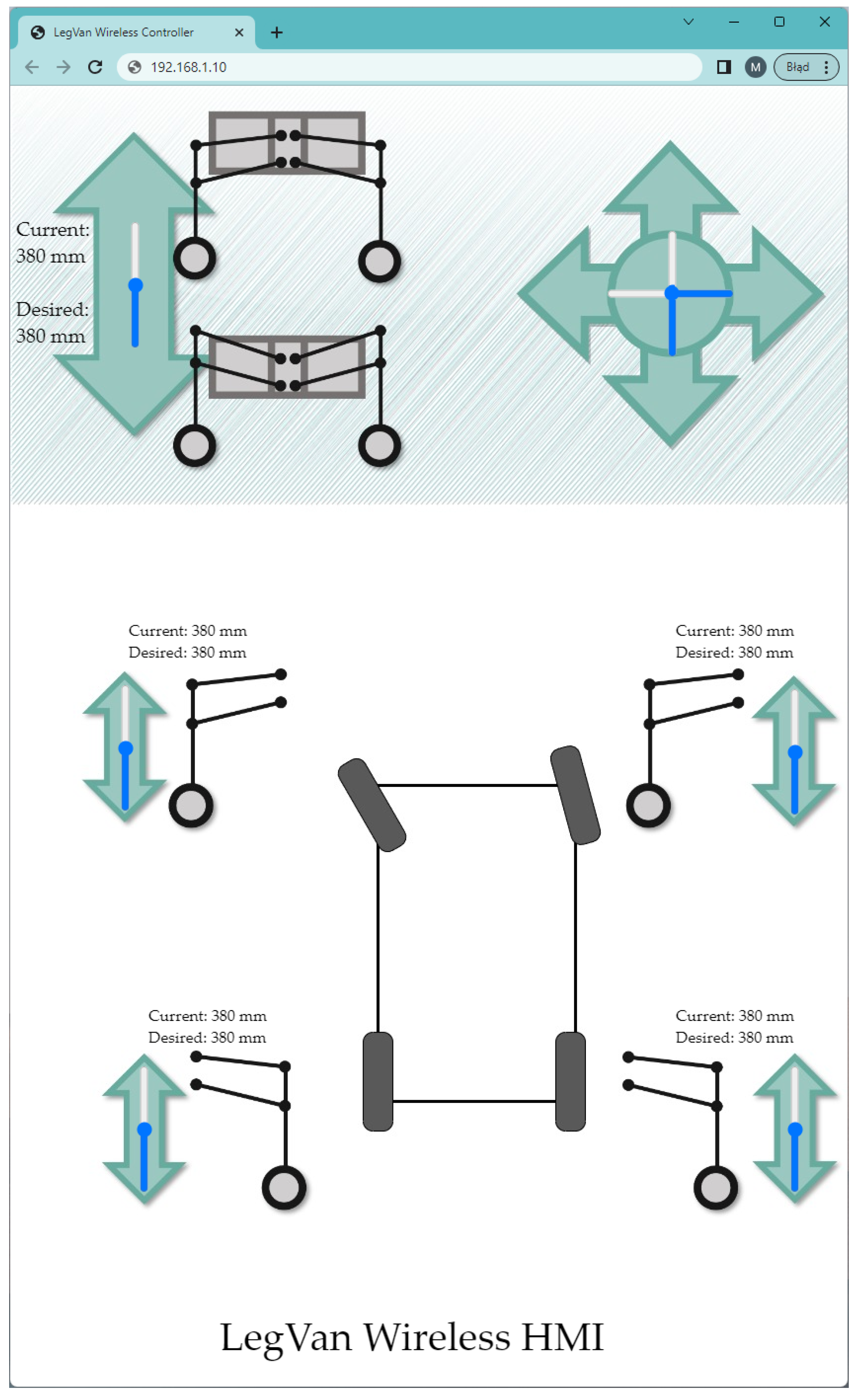
  • In the presented robot control interface, the leveling system does not work autonomously, so the adjustment of each leg height should be realized continuously.
  • The integration of the ESP32 controller with the HMI website is an efficient and low-cost solution for robotic systems.
  • The integration of the control website with a modern microcontroller unit allows operation of the robot using a touch screen.
  • The use of ESP32 allows a mobile robotic platform to be controlled with a smartphone.
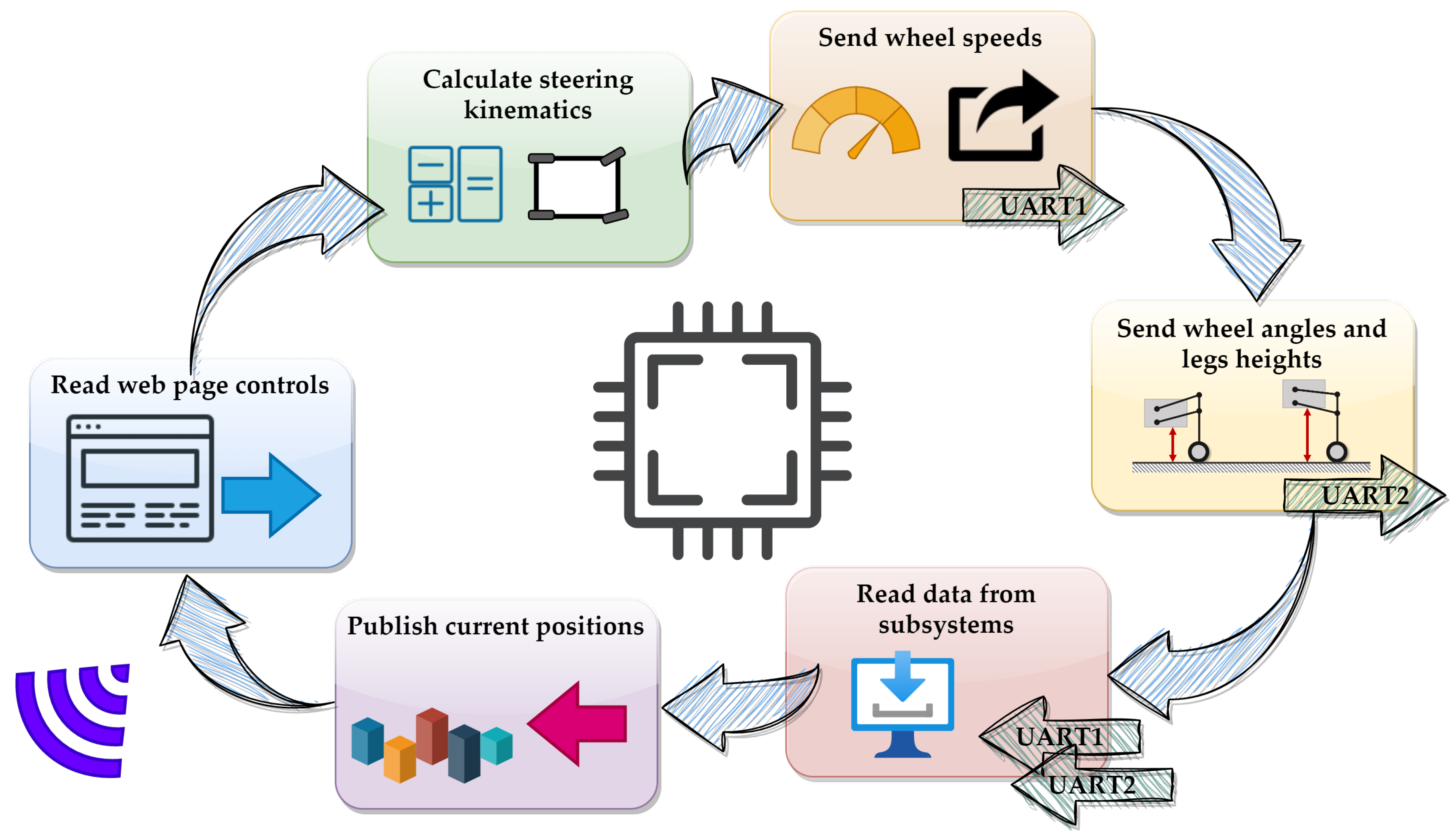
  • The use of a synchronous state machine implemented in the main controller is mandatory in order to synchronize all tasks in specific time windows.
  • The ESP32 is a modern and efficient tool that gives the possibility of synchronising basic control procedures with wireless communication and power demanding calculation of control kinematics.
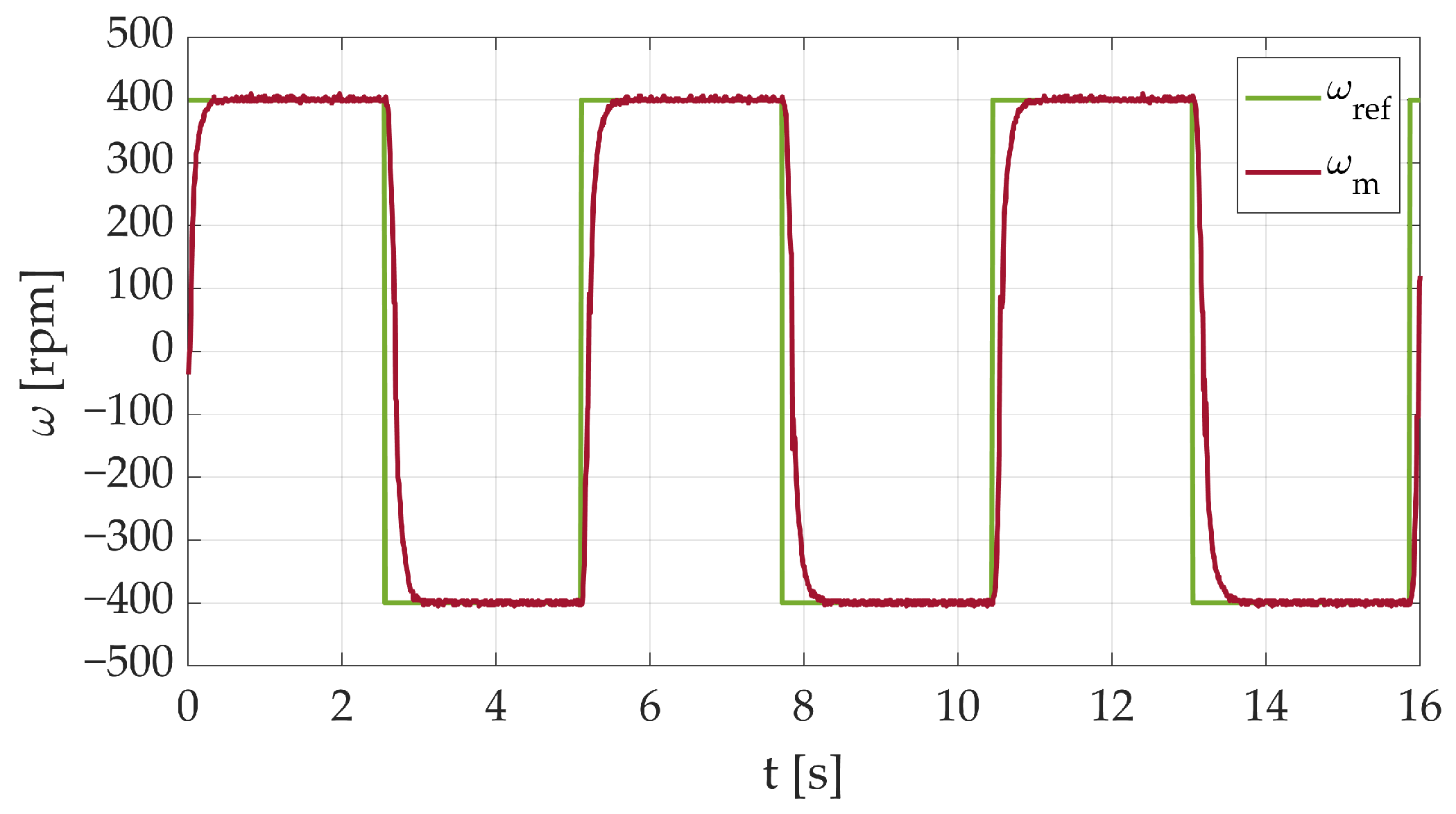
  • The FPA is a reasonable tool in the tuning process of the PI speed controller in the FOC structure, which ensures a high-precision speed control loop.
  • The UART protocol is a sufficient and user-friendly tool to be widely used in modern robotic platforms.
  • Raspberry Pi Pico is a low-cost entry level microcontroller unit, which ensures the possibility to realize advanced control structures in real time.
  • The FPA is an efficient tool for geometric synthesis of wheel-legged suspension.
  • Further improvements in the control system and HMI interface are considered.
  • Enhanced versions of the FPA are planned to be applied in further research activities.
  • Further research will cover both low-cost remote control and autonomous, AI-based systems applied to wheel-legged robots.
The aim of the presented research was to develop a remotely controlled robotic platform with adjustable legs heights. The novelty of the work deals with successful application of the flower pollination algorithm in mechanical synthesis and speed controller tuning, and the development of a low-cost ESP32-based wireless control web framework. The superiority of the proposed solution, over standard robotic platforms, is undoubtedly the possibility of adaptation of each wheel independently. The presented Wi-Fi-based control interface can be considered to be connected with WAN networks via mobile networks, enabling a virtually infinite range of control. Even without additional LTE/5G modems and using only an existing in-plant wireless network infrastructure, the robot can be controlled throughout the whole area by an operator from a single (stationary) PC. Thus, in further development, the operator can be replaced with a single master computer controlling (possibly AI-based) the swarm of the robots connected to a Wi-Fi network.

Author Contributions

Conceptualization, M.K. and M.M.; methodology, M.K., J.S. and M.M.; software, M.M.; validation, M.M. and J.S.; formal analysis, M.K.; investigation, M.K., M.M. and G.K.; resources, M.K., M.M. and J.S.; data curation, M.M. and G.K.; writing—original draft preparation, M.K., M.M., G.K. and J.S.; writing—review and editing, M.K., M.M., G.K. and J.S.; visualization, M.M. and G.K.; supervision, M.K.; project administration, M.K. All authors have read and agreed to the published version of the manuscript.

Funding

This research received no external funding.

Data Availability Statement

Not applicable.

Conflicts of Interest

The authors declare no conflict of interest.

Abbreviations

The following abbreviations are used in this manuscript:
HMIHuman–machine interface
SCADASupervisory control and data acquisition
MCUMicrocontroller unit
RFRadio frequency
RCRemote control
ADCAnalog-to-digital converter
IDEIntegrated development environment
PWMPulse width modulation
SPISerial peripheral interface
UARTUniversal asynchronous receiver/transmitter
BLDCBrushless DC motor
GPIOGeneral purpose input/output
I 2 CInter-integrated circuit
SVMSpace vector machine
FOCField-oriented control
PIProportional integral (controller)
PCBPrinted circuit board
FPAFlower pollination algorithm
EMFElectromagnetic field
DOFDegree of freedom
ROSRobotic Operating System
IoTInternet of Things
IoRTInternet of Robotic Things
LTELong-term evolution

References

  1. Lopes, D.; Coelho, L.; Silva, M.F. Development of a Collaborative Robotic Platform for Autonomous Auscultation. Appl. Sci. 2023, 13, 1604. [Google Scholar] [CrossRef]
  2. Min, H. Smart Warehousing as a Wave of the Future. Logistics 2023, 7, 30. [Google Scholar] [CrossRef]
  3. Liu, X.; Cao, J.; Yang, Y.; Jiang, S. CPS-Based Smart Warehouse for Industry 4.0: A Survey of the Underlying Technologies. Computers 2018, 7, 13. [Google Scholar] [CrossRef]
  4. Sangbae, K.; Wensing, P.M. Design of Dynamic Legged Robots. Foundations and Trends. Robotics 2017, 5, 117–190. [Google Scholar] [CrossRef]
  5. Wang, K.; Zhao, H.; Meng, F.; Zhang, X. Research on the Jumping Control Methods of a Quadruped Robot That Imitates Animals. Biomimetics 2023, 8, 36. [Google Scholar] [CrossRef]
  6. Ning, M.; Yang, J.; Zhang, Z.; Li, J.; Wang, Z.; Wei, L.; Feng, P. Method of Changing Running Direction of Cheetah-Inspired Quadruped Robot. Sensors 2022, 22, 9601. [Google Scholar] [CrossRef]
  7. Hutter, M.; Gehring, C.; Jud, D.; Lauber, A.; Dario Bellicoso, C.; Tsounis, V.; Hwangbo, J.; Bodie, K.; Fankhauser, P.; Bloesch, B.; et al. Anymal—A highly mobile and dynamic quadrupedal robot. In Proceedings of the 2016 IEEE/RSJ International Conference on Intelligent Robots and Systems (IROS), Daejeon, Republic of Korea, 9–14 October 2016; pp. 38–44. [Google Scholar] [CrossRef]
  8. Silva, M.F.; Goher, K.; Funk, M.; Tokhi, M.O.; Mendes, A. Robotics in Natural Settings: Proceedings of 25th Conference Series on Climbing and Walking Robots and Support Technologies for Mobile Machines CLAWAR 2022, Ponta Delgada, Portugal, 12–14 September 2022; Springer International Publishing: Berlin/Heidelberg, Germany, 2023. [Google Scholar] [CrossRef]
  9. Krejci, J.; Babiuch, M.; Babjak, J.; Suder, J.; Wierbica, R. Implementation of an Embedded System into the Internet of Robotic Things. Micromachines 2023, 14, 113. [Google Scholar] [CrossRef]
  10. Noga, M.; Juhas, M.; Gulan, M. Hybrid Virtual Commissioning of a Robotic Manipulator with Machine Vision Using a Single Controller. Sensors 2022, 22, 1621. [Google Scholar] [CrossRef] [PubMed]
  11. Omron Machine Iterface NA Series V457 CSM3.1. Omron Corporation Industrial Automation Company. 2023. Available online: https://assets.omron.eu/downloads/datasheet/en/v14/v457machine_interface_na5-v1_series_datasheet_en.pdf (accessed on 12 June 2023).
  12. Malarczyk, M.; Kaminski, M.; Szrek, J. Metaheuristic Approach to Synthesis of Suspension System of Mobile Robot for Mining Infrastructure Inspection. Sensors 2022, 22, 8839. [Google Scholar] [CrossRef]
  13. Roque, L.A.C.; Fontes, D.B.M.M.; Fontes, F.A.C.C. A Metaheuristic Approach to the Multi-Objective Unit Commitment Problem Combining Economic and Environmental Criteria. Energies 2017, 10, 2029. [Google Scholar] [CrossRef]
  14. Balderas, D.; Ortiz, A.; Méndez, E.; Ponce, P.; Molina, A. Empowering Digital Twin for Industry 4.0 using metaheuristic optimization algorithms: Case study PCB drilling optimization. Int. J. Adv. Manuf. Technol. 2021, 113, 1295–1306. [Google Scholar] [CrossRef]
  15. Sun, L.; Koopialipoor, M.; Jahed Armaghani, D.; Tarinejad, R.; Tahir, M.M. Applying a meta-heuristic algorithm to predict and optimize compressive strength of concrete samples. Eng. Comput. 2021, 37, 1133–1145. [Google Scholar] [CrossRef]
  16. Knypinski, L.; Kuroczycki, S.; Marquez, F.P.G. Minimization of Torque Ripple in the Brushless DC Motor Using Constrained Cuckoo Search Algorithm. Electronics 2021, 10, 2299. [Google Scholar] [CrossRef]
  17. Iwendi, C.; Maddikunta, P.K.R.; Gadekallu, T.R.; Lakshmanna, K.; Bashir, A.K.; Piran, M.J. A metaheuristic optimization approach for energy efficiency in the IoT networks. Softw. Pract. Exper. 2021, 51, 2558–2571. [Google Scholar] [CrossRef]
  18. Nassef, A.M.; Abdelkareem, M.A.; Maghrabie, H.M.; Baroutaji, A. Review of Metaheuristic Optimization Algorithms for Power Systems Problems. Sustainability 2023, 15, 9434. [Google Scholar] [CrossRef]
  19. Devarapalli, R.; Sinha, N.; Rao, B.; Knypinski, L.; Lakshmi, N.; Marquez, F. Allocation of real power generation based on computing over all generation cost: An approach of Salp Swarm Algorithm. Arch. Electr. Eng. 2021, 70, 337–349. [Google Scholar] [CrossRef]
  20. Alizadehsani, R.; Roshanzamir, M.; Izadi, N.H.; Gravina, R.; Kabir, H.M.D.; Nahavandi, D.; Alinejad-Rokny, H.; Khosravi, A.; Acharya, U.R.; Nahavandi, S.; et al. Swarm Intelligence in Internet of Medical Things: A Review. Sensors 2023, 23, 1466. [Google Scholar] [CrossRef] [PubMed]
  21. Rezk, H.; Olabi, A.G.; Wilberforce, T.; Sayed, E.T. A Comprehensive Review and Application of Metaheuristics in Solving the Optimal Parameter Identification Problems. Sustainability 2023, 15, 5732. [Google Scholar] [CrossRef]
  22. Ma, Z.; Wu, G.; Ponnuthurai, N.S.; Song, A.; Luo, Q. Performance assessment and exhaustive listing of 500+ nature-inspired metaheuristic algorithms. Swarm Evol. Comput. 2023, 77, 101248. [Google Scholar] [CrossRef]
  23. Knypinski, L. Performance analysis of selected metaheuristic optimization algorithms applied in the solution of an unconstrained task. COMPEL— Int. J. Comput. Math. Electr. Electron. Eng. 2021, 41, 1271–1284. [Google Scholar] [CrossRef]
  24. Khatri, M.; Dahiya, P.; Chaturvedi, A. Performance Enhancement of Suspension System of an Electric Vehicle Using Nature Inspired Meta-Heuristic Optimization Algorithm. In Ubiquitous Intelligent Systems. Smart Innovation, Systems and Technologies; Springer: Singapore, 2021; Volume 243. [Google Scholar] [CrossRef]
  25. Yildiz, B.S.; Yildiz, A.R.; Albak, E.I.; Abderazek, H.; Sait, S.M.; Bureerat, S. Butterfly optimization algorithm for optimum shape design of automobile suspension components. Mater. Test. 2020, 62, 365–370. [Google Scholar] [CrossRef]
  26. Yildiz, B.S. Optimal design of automotive suspension springs using Differential Evolution Algorithm. Uludağ Üniversitesi Mühendislik Fakültesi Dergisi 2018, 23, 207–214. [Google Scholar] [CrossRef]
  27. Zhu, L. Optimal Design of Suspension Control of Superconducting Gyroscope Rotor Based on Flower Pollination Algorithm. In Proceedings of the 2020 IEEE 3rd International Conference on Information Systems and Computer Aided Education (ICISCAE), Dalian, China, 27–29 September 2020; pp. 282–285. [Google Scholar] [CrossRef]
  28. Vasconcelos, G.J.Q.; Costa, G.S.R.; Spina, T.V.; Pedrini, H. Low-Cost Robot for Agricultural Image Data Acquisition. Agriculture 2023, 13, 413. [Google Scholar] [CrossRef]
  29. Boloz, L.; Bialy, W. Automation and Robotization of Underground Mining in Poland. Appl. Sci. 2020, 10, 7221. [Google Scholar] [CrossRef]
  30. Park, S.; Ahn, S.; Shin, J.; Kim, H.; Yang, J.; Kim, Y.; Lim, K.; Seo, T. WAVE: Last Mile Delivery Robotic Platform With Stair-Climbing Ability Via Four-Bar Linkage-Based Locomotion. IEEE/ASME Trans. Mechatron. 2023, 1–11. [Google Scholar] [CrossRef]
  31. Morlando, V.; Cacace, J.; Ruggiero, F. Online Feet Potential Fields for Quadruped Robots Navigation in Harsh Terrains. Robotics 2023, 12, 86. [Google Scholar] [CrossRef]
  32. Stefanski, T.; Zawarczynski, L. Parametric identification of PM motor mathematical models. Prz. Elektrotechniczny 2012, 88, 224–229. [Google Scholar]
  33. Sikora, A.; Zielonka, A.; Woźniak, M. Minimization of Energy Losses in the BLDC Motor for Improved Control and Power Supply of the System under Static Load. Sensors 2022, 22, 1058. [Google Scholar] [CrossRef] [PubMed]
  34. Mohanraj, D.; Aruldavid, R.; Verma, R.; Sathiyasekar, K.; Barnawi, A.B.; Chokkalingam, B.; Mihet-Popa, L. A Review of BLDC Motor: State of Art, Advanced Control Techniques, and Applications. IEEE Access 2022, 10, 54833–54869. [Google Scholar] [CrossRef]
  35. Furmanik, M.; Gorel, L.; Konvičný, D.; Rafajdus, P. Comparative Study and Overview of Field-Oriented Control Techniques for Six-Phase PMSMs. Appl. Sci. 2021, 11, 7841. [Google Scholar] [CrossRef]
  36. Gamazo-Real, J.C.; Vázquez-Sánchez, E.; Gómez-Gil, J. Position and Speed Control of Brushless DC Motors Using Sensorless Techniques and Application Trends. Sensors 2010, 10, 6901–6947. [Google Scholar] [CrossRef] [PubMed]
  37. Tang, X.; Zhang, Z.; Liu, X.; Liu, C.; Jiang, M.; Song, Y. A Novel Field-Oriented Control Algorithm for Permanent Magnet Synchronous Motors in 60° Coordinate Systems. Actuators 2023, 12, 92. [Google Scholar] [CrossRef]
  38. Gupta, G.; Sreejeth, M. Study and Analysis of Field Oriented Control of Brushless DC Motor Drive using Hysteresis Current Control Technique. In Proceedings of the 2nd Asian Conference on Innovation in Technology (ASIANCON), Ravet, India, 26–28 August 2022; pp. 1–5. [Google Scholar] [CrossRef]
  39. Przybocki, P.; Vassilakis, V.G. An Analysis into Physical and Virtual Power Draw Characteristics of Embedded Wireless Sensor Network Devices under DoS and RPL-Based Attacks. Sensors 2023, 23, 2605. [Google Scholar] [CrossRef] [PubMed]
  40. Szabat, K.; Orlowska-Kowalska, T. Application of the Kalman Filters in the Self-Commissioning High-Performance Drive System with an Elastic Joint. In Kalman Filter Recent Advances and Applications; Intech: London, UK, 2009. [Google Scholar] [CrossRef]
  41. Yakub, M.F.H.; Martono, W.; Akmeliawati, R. Vibration control of two-mass rotary system using improved NCTF controller for positioning systems. In Proceedings of the IEEE Control and System Graduate Research Colloquium (ICSGRC 2010), Shah Alam, Malaysia, 22 June 2010; pp. 61–67. [Google Scholar] [CrossRef]
  42. Bitria, R.; Palacín, J. Optimal PID Control of a Brushed DC Motor with an Embedded Low-Cost Magnetic Quadrature Encoder for Improved Step Overshoot and Undershoot Responses in a Mobile Robot Application. Sensors 2022, 22, 7817. [Google Scholar] [CrossRef] [PubMed]
  43. Abdullah, L.; Jamaludin, Z.; Rafan, N.A.; Jamaludin, J.; Chiew, T.H. Assessment on tracking error performance of Cascade P/PI, NPID and N-Cascade controller for precise positioning of xy table ballscrew drive system. In Proceedings of the 5th International Conference on Mechatronics (ICOM’13), Kuala Lumpur, Malaysia, 2–4 July 2013. [Google Scholar] [CrossRef]
  44. Raspberry Pi Pico Technical Reference. Available online: https://datasheets.raspberrypi.com/rp2040/rp2040-datasheet.pdf (accessed on 12 June 2023).
  45. STM32F103 Technical Reference. Available online: https://www.st.com/resource/en/datasheet/stm32f103c8.pdf (accessed on 12 June 2023).
  46. ESP32 Technical Reference. Available online: https://www.espressif.com/sites/default/files/documentation/esp32_technical_reference_manual_en.pdf (accessed on 12 June 2023).
  47. Yang, X.S. Flower Pollination Algorithm for Global Optimization. In Proceedings of the Unconventional Computation and Natural Computation: 11th International Conference (UCNC 2012), Orleans, France, 3–7 September 2012; Springer: Berlin/Heidelberg, Germany, 2012. [Google Scholar] [CrossRef]
  48. Wang, Y.; Zhang, D.; Renner, S. A new self-pollination mechanism. Nature 2004, 431, 39–40. [Google Scholar] [CrossRef] [PubMed]
  49. Frankel, R.; Galun, E. Pollination Mechanisms, Reproduction and Plant Breeding; Springer: Berlin/Heidelberg, Germany, 1977. [Google Scholar] [CrossRef]
  50. Lalljith, S.; Fleming, I.; Pillay, U.; Naicker, K.; Naidoo, Z.J.; Saha, J.K. Applications of Flower Pollination Algorithm in Electrical Power Systems: A Review. IEEE Access 2022, 10, 8924–8947. [Google Scholar] [CrossRef]
  51. Abdel-Basset, M.; Mohamed, R.; Saber, S.; Askar, S.S.; Abouhawwash, M. Modified Flower Pollination Algorithm for Global Optimization. Mathematics 2021, 9, 1661. [Google Scholar] [CrossRef]
  52. Li, G.; Wang, T.; Chen, Q.; Shao, P.; Xiong, N.; Vasilakos, A. A Survey on Particle Swarm Optimization for Association Rule Mining. Electronics 2022, 11, 3044. [Google Scholar] [CrossRef]
  53. Brezocnik, L.; Fister, I.; Podgorelec, V. Swarm Intelligence Algorithms for Feature Selection: A Review. Appl. Sci. 2018, 8, 1521. [Google Scholar] [CrossRef]
  54. Tan, X.; Liu, D.; Xiong, H. Optimal Control Method of Path Tracking for Four-Wheel Steering Vehicles. Actuators 2022, 11, 61. [Google Scholar] [CrossRef]
  55. Balkwill, J. Chapter 7—Suspension Kinematics in Performance Vehicle Dynamics. In Engineering and Applications; Elsevier: Oxford, UK, 2018; pp. 197–239. [Google Scholar] [CrossRef]
Figure 1. The topology of microcontroller system used for remote control of wheel-legged robot.
Futureinternet 15 00303 g001
Figure 2. The principles of field-oriented control.
Futureinternet 15 00303 g002
Figure 3. Field-oriented control structure.
Futureinternet 15 00303 g003
Figure 4. The position control structure applied for the chassis.
Futureinternet 15 00303 g004
Figure 6. Four-bar linkage suspension structure of analyzed robot.
Futureinternet 15 00303 g006
Figure 7. Flowchart of the flower pollination algorithm—the pollination mechanism is presented in yellow blocks.
Futureinternet 15 00303 g007
Figure 8. The developed prototype of the LegVan3 robot, (a)—the down position (regular driving position), and (b)—the elevated position.
Futureinternet 15 00303 g008
Figure 9. Changes of cost function value during calculations of the FPA.
Futureinternet 15 00303 g009
Figure 10. Speed transient of the BLDC motor implemented in the robot.
Futureinternet 15 00303 g010
Figure 11. Screenshot of developed website.
Futureinternet 15 00303 g011
Figure 12. Data processing in the ESP32.
Futureinternet 15 00303 g012
Figure 13. The kinematics analysis of robot (control part).
Futureinternet 15 00303 g013
Table 2. The results of the geometrical synthesis.
ParameterValue
a32 cm
b[10,15] cm
c[32,40] cm
e40 cm
x A [5,10] cm
y A [0,5] cm
x D [0,5] cm
y D [15,20] cm
Table 3. Parameters of the flower pollination algorithm.
ParameterValue
Population size20
Main loop iteration count20
Probability switch, P0.8
[ L b , U b ] [0,20]
Disclaimer/Publisher’s Note: The statements, opinions and data contained in all publications are solely those of the individual author(s) and contributor(s) and not of MDPI and/or the editor(s). MDPI and/or the editor(s) disclaim responsibility for any injury to people or property resulting from any ideas, methods, instructions or products referred to in the content.

