


Precoding for RIS-Assisted Multi-User MIMO-DQSM Transmission Systems

 ,
,  ,
,  ,
,  , and
, and
Abstract
:1. Introduction
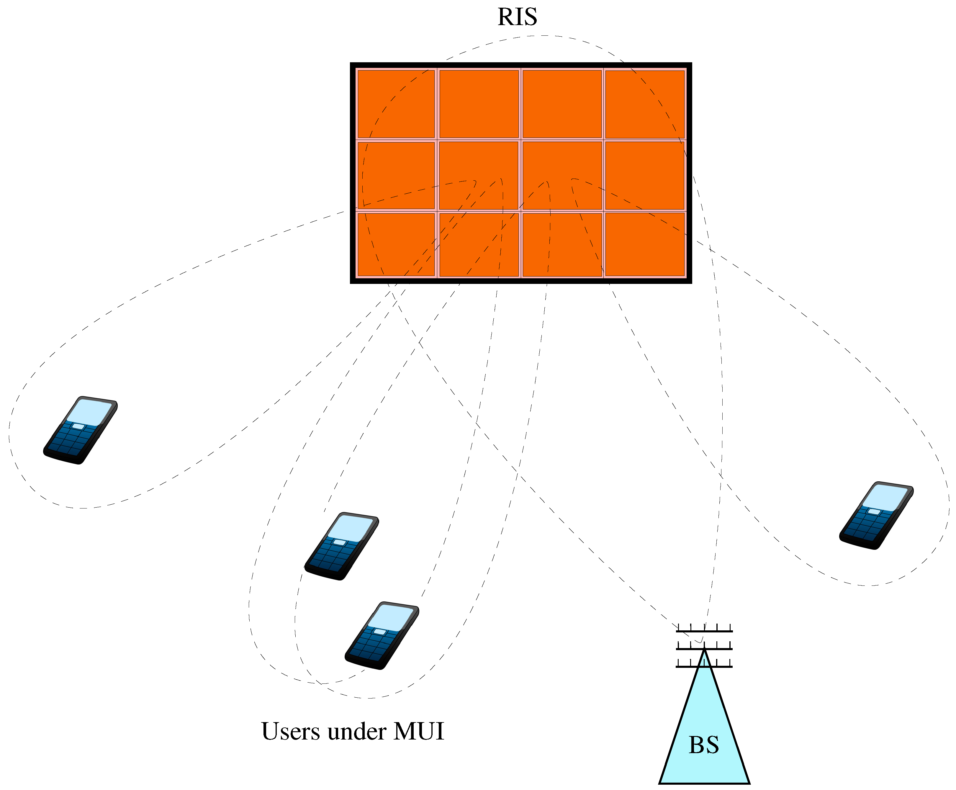
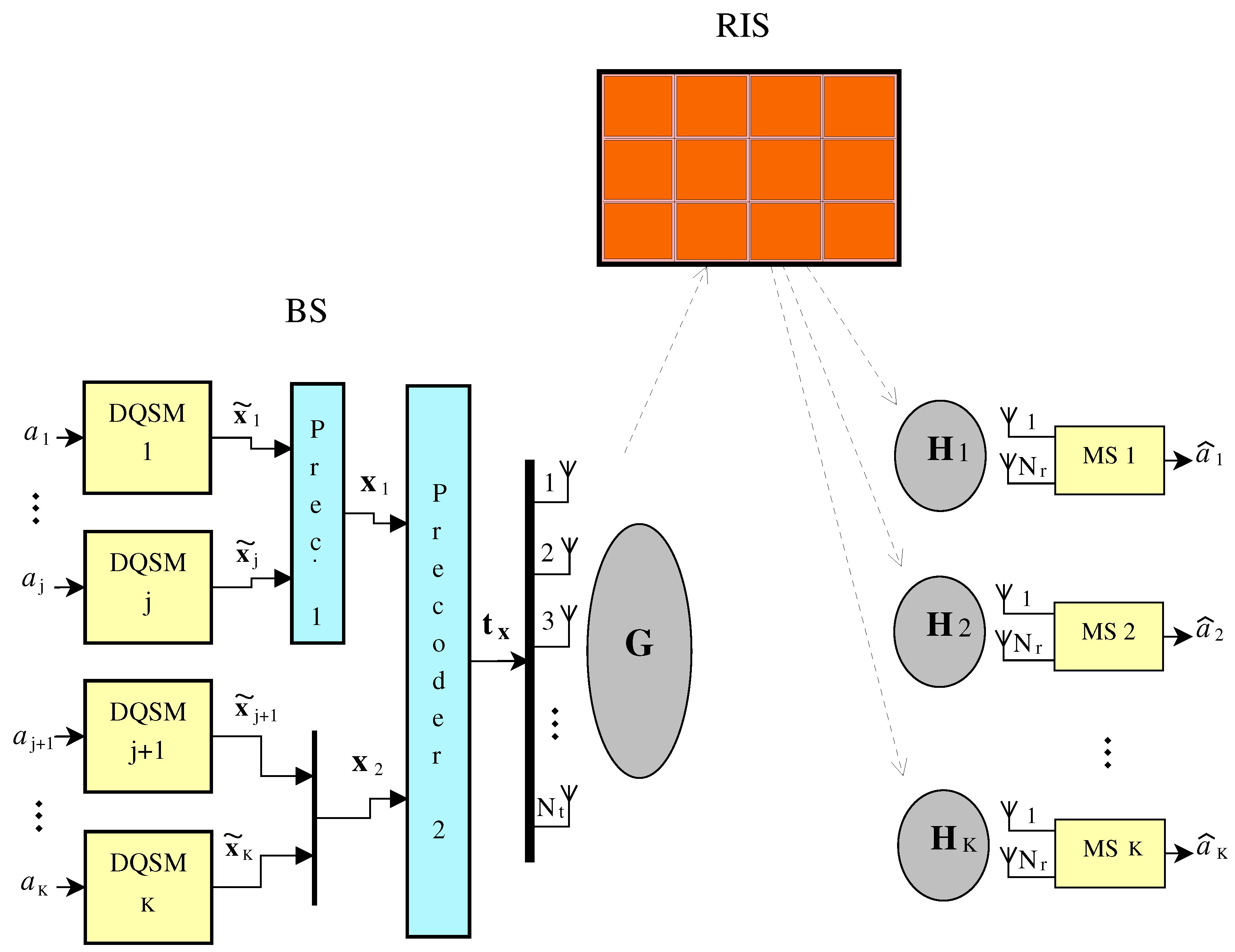
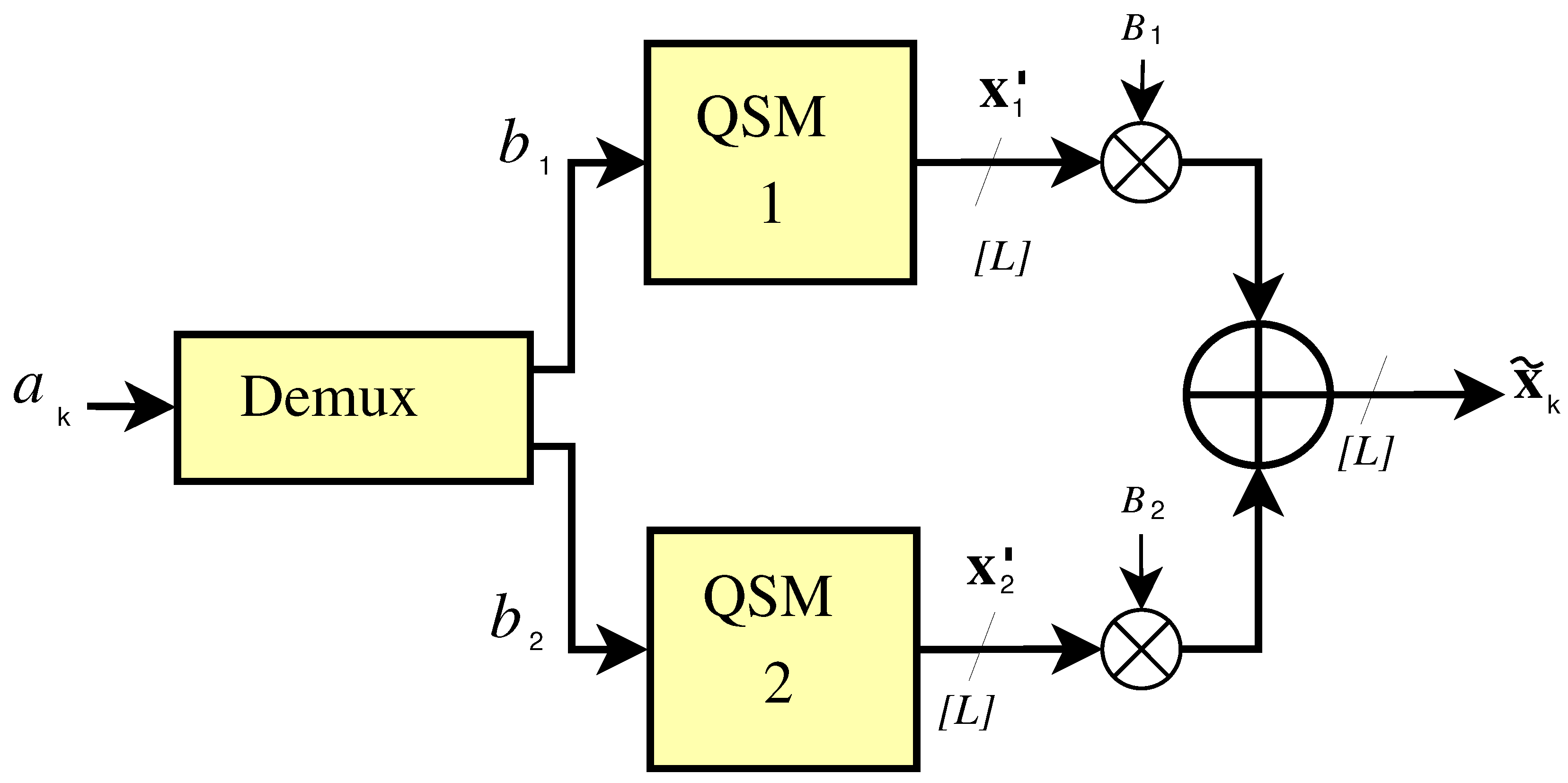
2. System Model
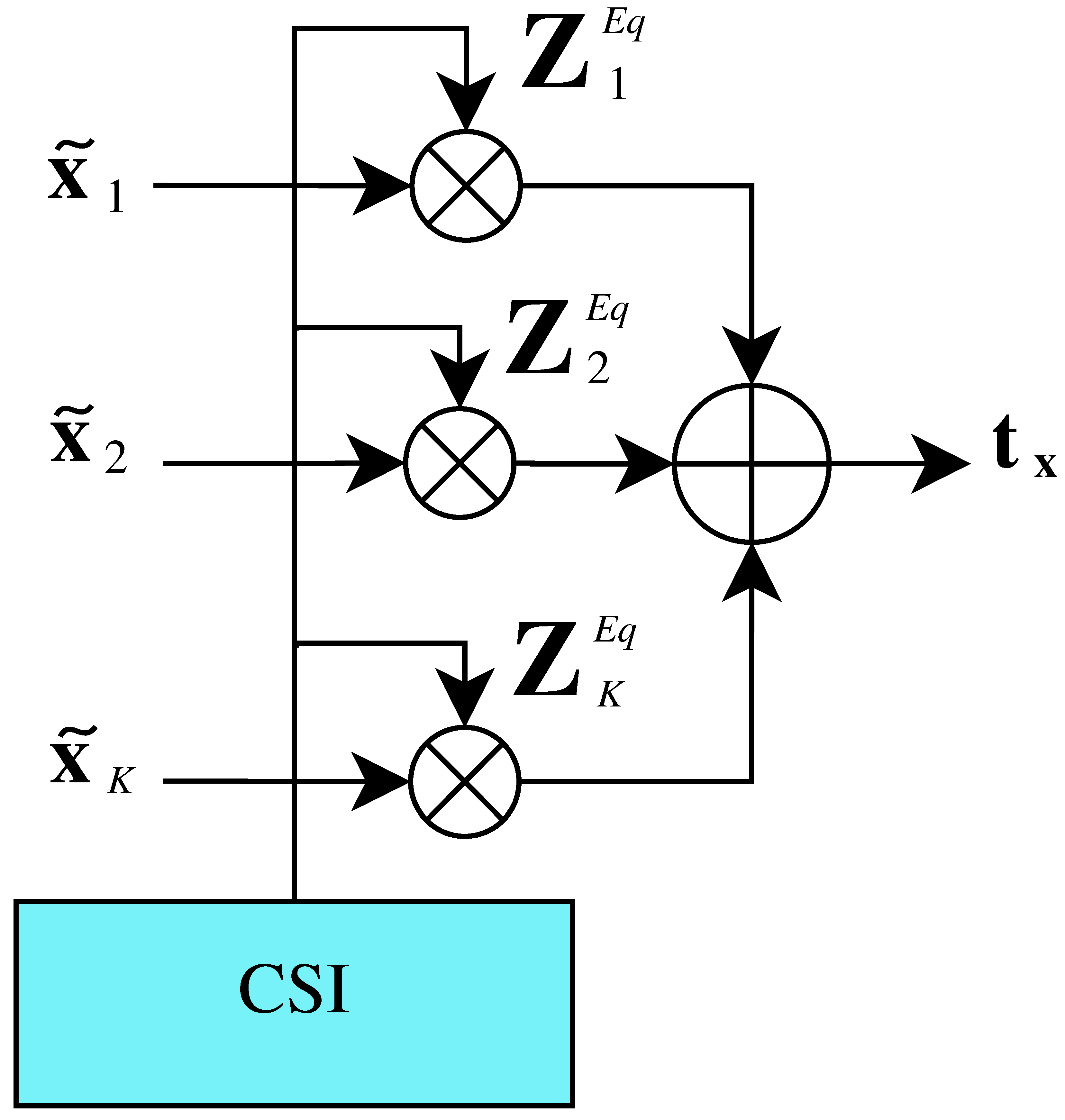
2.1. Transmission
2.2. Reception
3. Channel Model
4. Interference Cancellation
4.1. Strategy I. ZF-BD Precoding
4.2. Strategy II. Joint-BD Precoding
5. Detection
Detection Complexity
6. Results and Discussion
6.1. Detection Complexity Results
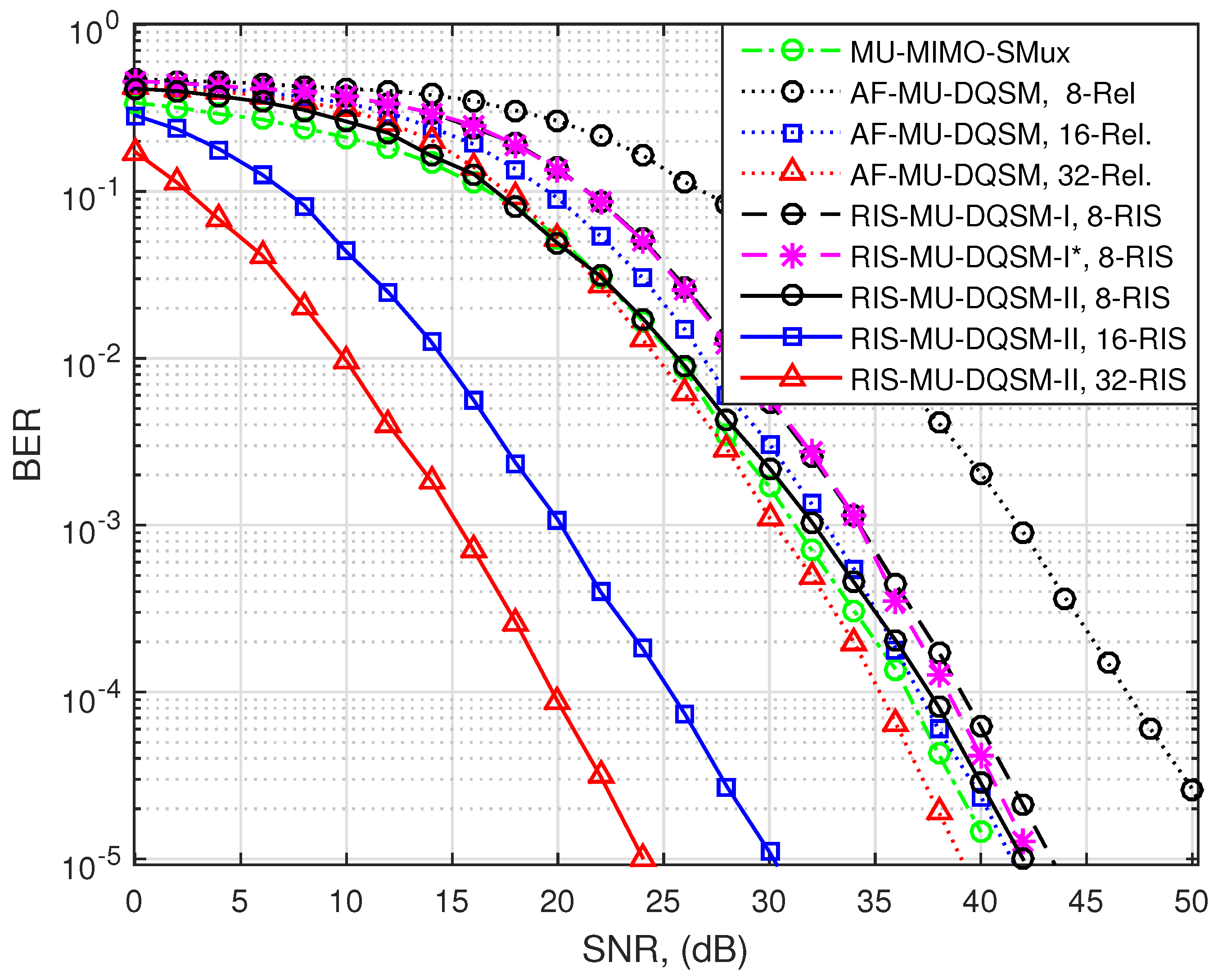
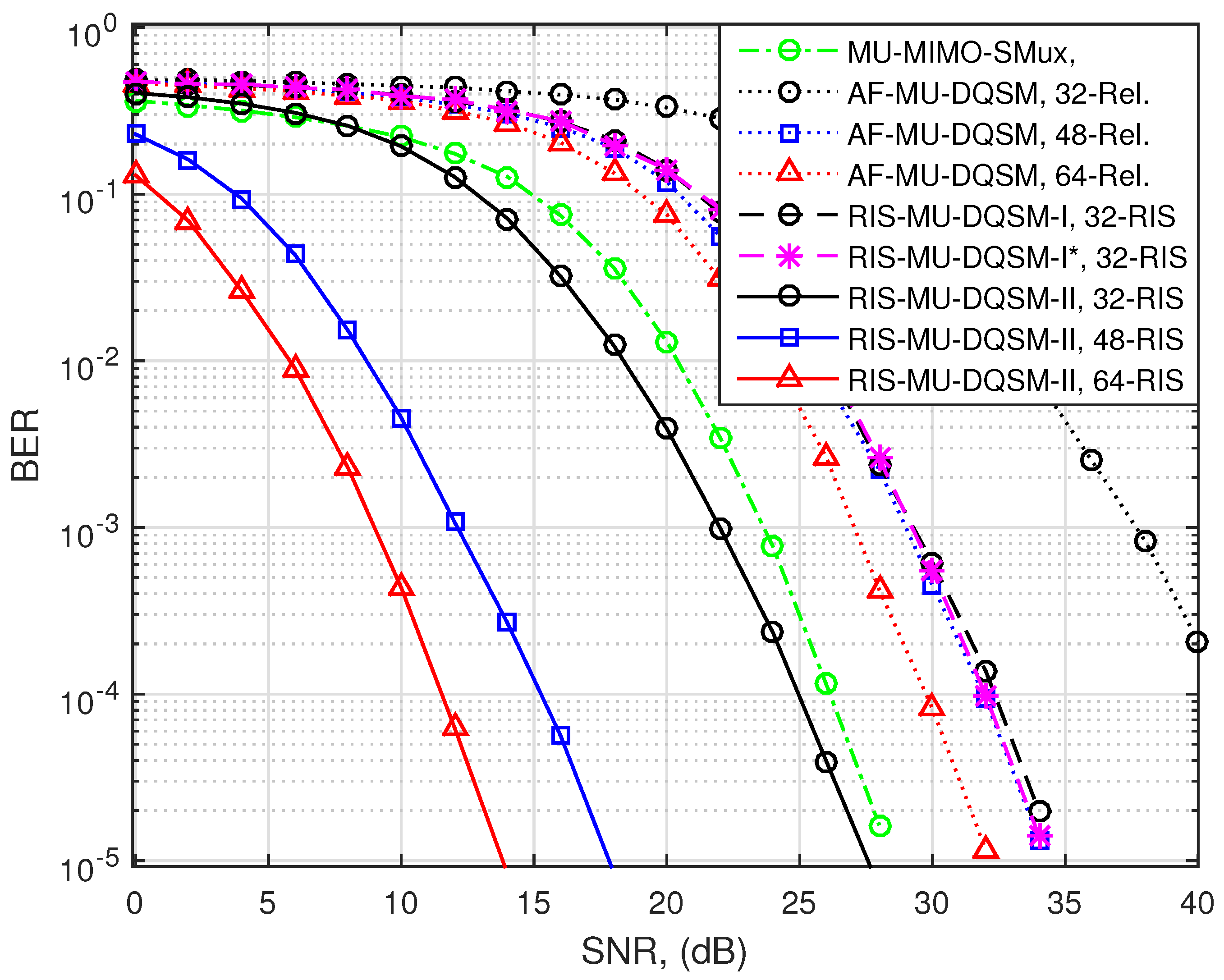
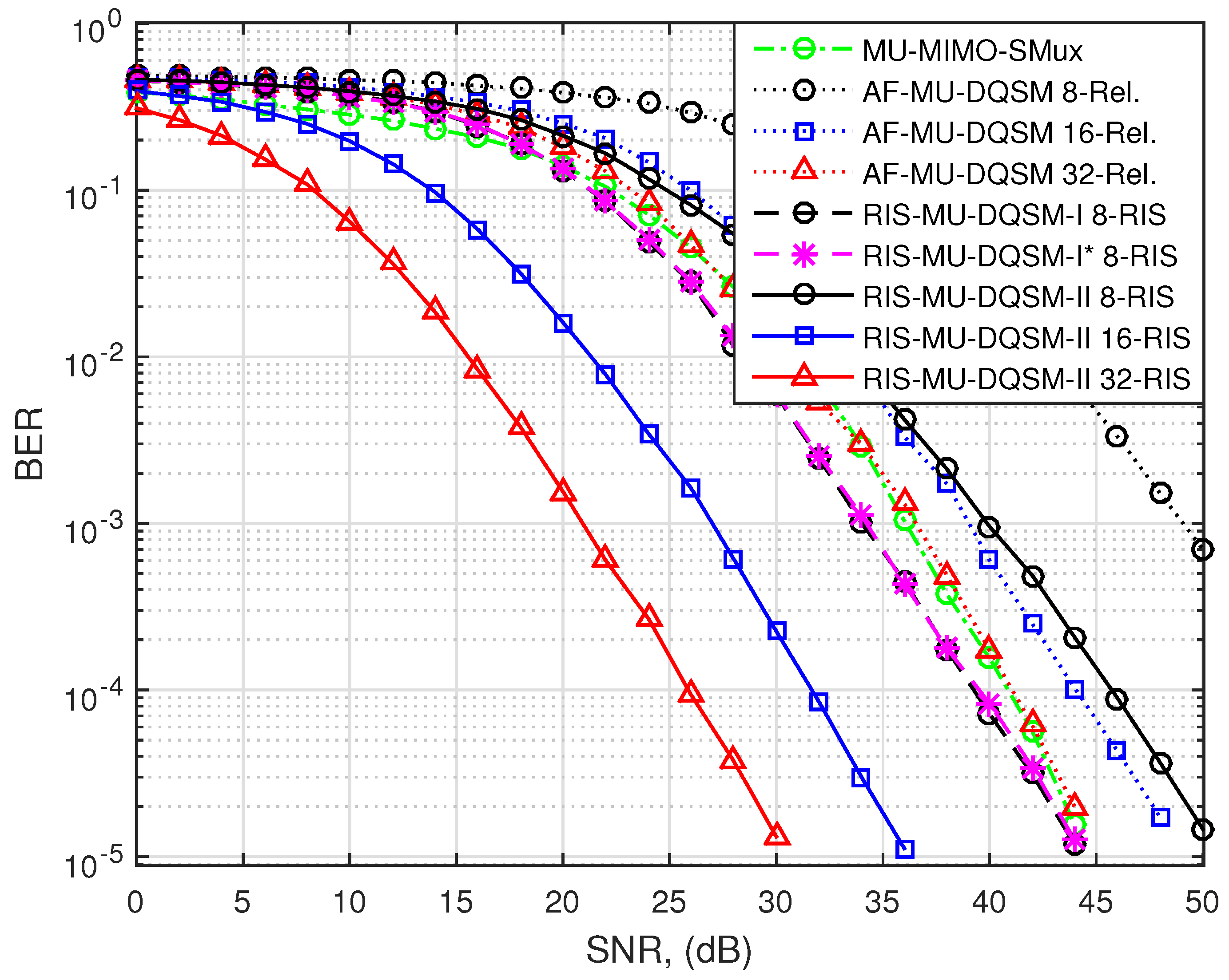
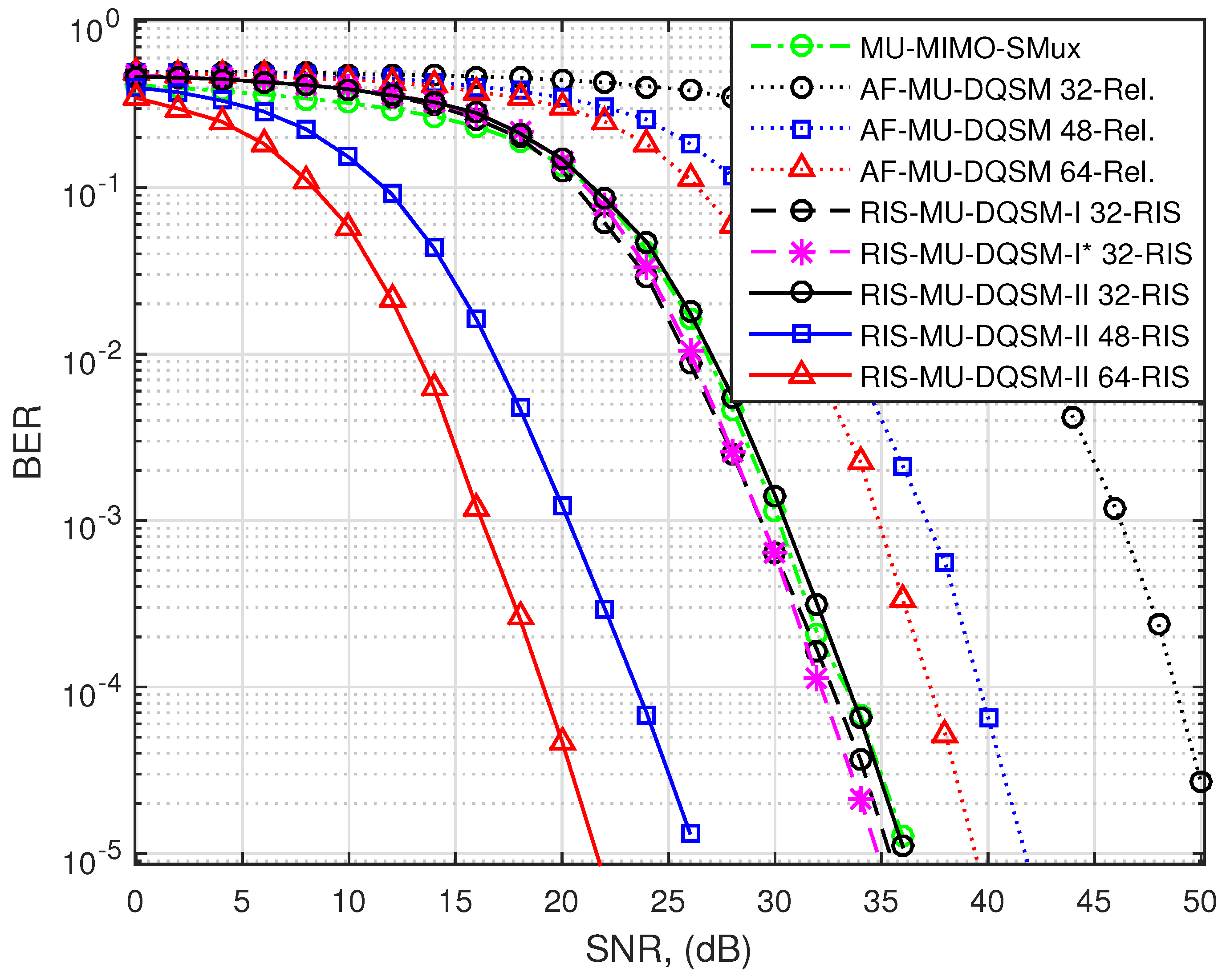
6.2. BER Performance
6.3. Discussion
7. Conclusions
Author Contributions
Funding
Data Availability Statement
Conflicts of Interest
References
- Huo, Y.; Lin, X.; Di, B.; Zhang, H.; Hernando, F.J.L.; Tan, A.S.; Mumtaz, S.; Demir, Ö.T.; Chen-Hu, K. Technology Trends for Massive MIMO towards 6G. Sensors 2023, 23, 6062. [Google Scholar] [CrossRef]
- Pérez-Adán, D.; Fresnedo, Ó.; González-Coma, J.P.; Castedo, L. Intelligent Reflective Surfaces for Wireless Networks: An Overview of Applications, Approached Issues, and Open Problems. Electronics 2021, 10, 2345. [Google Scholar] [CrossRef]
- He, X.; Cui, Y.; Tentzeris, M. Tile-based massively scalable MIMO and phased arrays for 5G/B5G-enabled smart skins and reconfigurable intelligent surfaces. Sci. Rep. 2022, 12, 2741. [Google Scholar] [CrossRef]
- Wang, Y.; Zhang, W.; Chen, Y.; Wang, C.X.; Sun, J. Novel Multiple RIS-Assisted Communications for 6G Networks. IEEE Commun. Lett. 2022, 26, 1413–1417. [Google Scholar] [CrossRef]
- Tang, W.; Chen, M.Z.; Chen, X.; Dai, J.Y.; Han, Y.; Di Renzo, M.; Zeng, Y.; Jin, S.; Cheng, Q.; Cui, T.J. Wireless Communications With Reconfigurable Intelligent Surface: Path Loss Modeling and Experimental Measurement. IEEE Trans. Wirel. Commun. 2021, 20, 421–439. [Google Scholar] [CrossRef]
- Basar, E.; Di Renzo, M.; De Rosny, J.; Debbah, M.; Alouini, M.S.; Zhang, R. Wireless Communications Through Reconfigurable Intelligent Surfaces. IEEE Access 2019, 7, 116753–116773. [Google Scholar] [CrossRef]
- Malathy, S.; Jayarajan, P.; Ojukwu, H.; Qamar, F.; Hindia, M.H.D.N.; Dimyati, K.; Noordin, K.A.; Amiri, I.S. A review on energy management issues for future 5G and beyond network. Wirel. Netw. 2021, 27, 2691–2718. [Google Scholar] [CrossRef]
- Alanazi, F. Intelligent reflecting surfaces with energy harvesting for Nakagami fading channels. Telecommun. Syst. 2021, 78, 351–361. [Google Scholar] [CrossRef]
- Alamzadeh, I.; Alexandropoulos, G.; Shlezinger, N.; Imani, M.F. A reconfigurable intelligent surface with integrated sensing capability. Sci. Rep. 2021, 11, 20737. [Google Scholar] [CrossRef] [PubMed]
- Zhang, H.; Di, B. Intelligent Omni-Surfaces: Simultaneous Refraction and Reflection for Full-Dimensional Wireless Communications. IEEE Commun. Surv. Tutor. 2022, 24, 1997–2028. [Google Scholar] [CrossRef]
- Bansal, A.; Agrawal, N.; Singh, K.; Li, C.P. RIS Selection Scheme for UAV-based Multi-RIS-aided Multiuser Downlink Network with Imperfect and Outdated CSI. IEEE Trans. Commun. 2023, 71, 4650–4664. [Google Scholar] [CrossRef]
- Zargari, S.; Khalili, A.; Zhang, R. Energy Efficiency Maximization via Joint Active and Passive Beamforming Design for Multiuser MISO IRS-Aided SWIPT. IEEE Wirel. Commun. Lett. 2021, 10, 557–561. [Google Scholar] [CrossRef]
- Wang, X.; Fei, Z.; Guo, J.; Zheng, Z.; Li, B. RIS-Assisted Spectrum Sharing Between MIMO Radar and MU-MISO Communication Systems. IEEE Wirel. Commun. Lett. 2021, 10, 594–598. [Google Scholar] [CrossRef]
- Papazafeiropoulos, A.K.; Pan, C.; Kourtessis, P.; Chatzinotas, S.; Senior, J.M. Intelligent Reflecting Surface-assisted MU-MISO Systems with Imperfect Hardware: Channel Estimation, Beamforming Design. arXiv 2021, arXiv:2102.05333. [Google Scholar] [CrossRef]
- Huang, C.; Mo, R.; Yuen, C. Reconfigurable Intelligent Surface Assisted Multiuser MISO Systems Exploiting Deep Reinforcement Learning. IEEE J. Sel. Areas Commun. 2020, 38, 1839–1850. [Google Scholar] [CrossRef]
- Souto, N.; Silva, J.C. Joint Beamforming Algorithm for Multi-stream MIMO Systems Assisted by Multiple Reconfigurable Intelligent Surfaces. IEEE Open J. Commun. Soc. 2023, 4, 1317–1333. [Google Scholar] [CrossRef]
- Semmler, D.; Joham, M.; Utschick, W. Linear Precoding in the Intelligent Reflecting Surface Assisted MIMO Broadcast Channel. In Proceedings of the 2022 IEEE 23rd International Workshop on Signal Processing Advances in Wireless Communication (SPAWC), Oulu, Finland, 4–6 July 2022; pp. 1–5. [Google Scholar] [CrossRef]
- Cai, S.; Qu, H.; Zhang, J.; Shi, X.; Zhu, H. Symbol-Level Precoding Design in IRS-Aided Secure Wireless Communication Systems. IEEE Wirel. Commun. Lett. 2022, 11, 2315–2319. [Google Scholar] [CrossRef]
- Castillo-Soria, F.; Cortez, J.; Gutiérrez, C.; Luna-Rivera, M.; Garcia-Barrientos, A. Extended quadrature spatial modulation for MIMO wireless communications. Phys. Commun. 2019, 32, 88–95. [Google Scholar] [CrossRef]
- Basar, E. Reconfigurable Intelligent Surface-Based Index Modulation: A New Beyond MIMO Paradigm for 6G. IEEE Trans. Commun. 2020, 68, 3187–3196. [Google Scholar] [CrossRef]
- Bamisaye, A.J.; Quazi, T. Quadrature spatial modulation-aided single-input multiple-output-media-based modulation. Int. J. Commun. Syst. 2021, 34, e4883. [Google Scholar] [CrossRef]
- Khan, M.H.A.; Chung, J.; Lee, M. Lattice reduction aided with block diagonalization for multiuser MIMO systems. J. Wirel. Commun. Netw. 2015, 2015, 254. [Google Scholar] [CrossRef]
- Castillo-Soria, F. AF relay assisted multiuser MIMO-DQSM downlink transmission system. Electron. Lett. 2020, 56, 682–684. [Google Scholar] [CrossRef]
- Nadeem, Q.U.A.; Kammoun, A.; Chaaban, A.; Debbah, M.; Alouini, M.S. Asymptotic Max-Min SINR Analysis of Reconfigurable Intelligent Surface Assisted MISO Systems. IEEE Trans. Wirel. Commun. 2020, 19, 7748–7764. [Google Scholar] [CrossRef]
- Huang, C.; Zappone, A.; Alexandropoulos, G.C.; Debbah, M.; Yuen, C. Reconfigurable Intelligent Surfaces for Energy Efficiency in Wireless Communication. IEEE Trans. Wirel. Commun. 2019, 18, 4157–4170. [Google Scholar] [CrossRef]
- Mohades, Z.; Tabataba, V.V. Deep Neural Network for Compressive Sensing and Application to Massive MIMO Channel Estimation. Circuits Syst. Signal Process. 2021, 40, 4474–4489. [Google Scholar] [CrossRef]
- Rao, X.; Lau, V.K.N.; Kong, X. CSIT estimation and feedback for FDD multi-user massive MIMO systems. In Proceedings of the 2014 IEEE International Conference on Acoustics, Speech and Signal Processing (ICASSP), Florence, Italy, 4–9 May 2014; pp. 3157–3161. [Google Scholar] [CrossRef]
- Han, Y.; Tang, W.; Jin, S.; Wen, C.K.; Ma, X. Large Intelligent Surface-Assisted Wireless Communication Exploiting Statistical CSI. IEEE Trans. Veh. Technol. 2019, 68, 8238–8242. [Google Scholar] [CrossRef]
- Mesleh, R.; Ikki, S.S.; Aggoune, H.M. Quadrature Spatial Modulation. IEEE Trans. Veh. Technol. 2015, 64, 2738–2742. [Google Scholar] [CrossRef]
- Martin, C.; Ottersten, B. Asymptotic eigenvalue distributions and capacity for MIMO channels under correlated fading. IEEE Trans. Wirel. Commun. 2004, 3, 1350–1359. [Google Scholar] [CrossRef]
- Wiesel, A.; Eldar, Y.C.; Shamai, S. Zero-Forcing Precoding and Generalized Inverses. IEEE Trans. Signal Process. 2008, 56, 4409–4418. [Google Scholar] [CrossRef]
- Raviv, L.o.; Leshem, A. Scheduling for Multi-User Multi-Input Multi-Output Wireless Networks with Priorities and Deadlines. Future Internet 2019, 11, 172. [Google Scholar] [CrossRef]
- Spencer, Q.; Swindlehurst, A.; Haardt, M. Zero-forcing methods for downlink spatial multiplexing in multiuser MIMO channels. IEEE Trans. Signal Process. 2004, 52, 461–471. [Google Scholar] [CrossRef]
- Li, Q.; Wen, M.; Wang, S.; Alexandropoulos, G.C.; Wu, Y.C. Space Shift Keying With Reconfigurable Intelligent Surfaces: Phase Configuration Designs and Performance Analysis. IEEE Open J. Commun. Soc. 2021, 2, 322–333. [Google Scholar] [CrossRef]
- Kumaravelu, V.B.; Imoize, A.L.; Soria, F.R.C.; Velmurugan, P.G.S.; Thiruvengadam, S.J.; Do, D.T.; Murugadass, A. RIS-Assisted Fixed NOMA: Outage Probability Analysis and Transmit Power Optimization. Future Internet 2023, 15, 249. [Google Scholar] [CrossRef]


| Input Bits, | QSM 1 | QSM 2 | Output Signal |
|---|---|---|---|
| DQSM | |||
| 0000 0000 | |||
| 0000 0001 | |||
| 0000 0010 | |||
| 0000 0011 | |||
| 0000 0100 | |||
| 0000 0101 | |||
| 0000 0110 | |||
| 0000 0111 | |||
| 0000 1000 | |||
| 0000 1001 | |||
| 0000 1010 | |||
| 0000 1011 | |||
| 0000 1100 | |||
| 0000 1101 | |||
| 0000 1110 | |||
| 0000 1111 |
| Operation | Complexity |
|---|---|
| Subtractions | |
| MRC | |
| Ordering | |
| System | RIS-MU | RIS-MU | AF-MU | MU-MIMO |
|---|---|---|---|---|
| Configuration | DQSM-I | DQSM-II | DQSM | SMux |
| 9088 | 10,112 | 10,112 | 12,032 | |
| 283,648 | 316,416 | 316,416 | 643,072 | |
| Scheme | Configuration | QAM Mod. |
|---|---|---|
| RIS-MU-DQSM-I | 4-QAM | |
| RIS-MU-DQSM-II | 4-QAM | |
| AF-MU-DQSM | 4-QAM | |
| MU-MIMO-SMux | 8-QAM |
| Scheme | Configuration | QAM Mod. |
|---|---|---|
| RIS-MU-DQSM-I | 4-QAM | |
| RIS-MU-DQSM-II | 4-QAM | |
| AF-MU-DQSM | 4-QAM | |
| MU-MIMO-SMux | 8-QAM |
Disclaimer/Publisher’s Note: The statements, opinions and data contained in all publications are solely those of the individual author(s) and contributor(s) and not of MDPI and/or the editor(s). MDPI and/or the editor(s) disclaim responsibility for any injury to people or property resulting from any ideas, methods, instructions or products referred to in the content. |
© 2023 by the authors. Licensee MDPI, Basel, Switzerland. This article is an open access article distributed under the terms and conditions of the Creative Commons Attribution (CC BY) license (https://creativecommons.org/licenses/by/4.0/).
Share and Cite
Castillo-Soria, F.R.; Del Puerto-Flores, J.A.; Azurdia-Meza, C.A.; Babu Kumaravelu, V.; Simón, J.; Gutierrez, C.A. Precoding for RIS-Assisted Multi-User MIMO-DQSM Transmission Systems. Future Internet 2023, 15, 299. https://doi.org/10.3390/fi15090299
Castillo-Soria FR, Del Puerto-Flores JA, Azurdia-Meza CA, Babu Kumaravelu V, Simón J, Gutierrez CA. Precoding for RIS-Assisted Multi-User MIMO-DQSM Transmission Systems. Future Internet. 2023; 15(9):299. https://doi.org/10.3390/fi15090299
Chicago/Turabian StyleCastillo-Soria, Francisco R., J. Alberto Del Puerto-Flores, Cesar A. Azurdia-Meza, Vinoth Babu Kumaravelu, Jorge Simón, and Carlos A. Gutierrez. 2023. "Precoding for RIS-Assisted Multi-User MIMO-DQSM Transmission Systems" Future Internet 15, no. 9: 299. https://doi.org/10.3390/fi15090299
APA StyleCastillo-Soria, F. R., Del Puerto-Flores, J. A., Azurdia-Meza, C. A., Babu Kumaravelu, V., Simón, J., & Gutierrez, C. A. (2023). Precoding for RIS-Assisted Multi-User MIMO-DQSM Transmission Systems. Future Internet, 15(9), 299. https://doi.org/10.3390/fi15090299