

An Ontology for Spatio-Temporal Media Management and an Interactive Application

 , , ,
, , ,  and
and
Abstract
1. Introduction
2. Related Works
2.1. Related Ontologies and Studies
2.2. Spatial Acoustic Technology
2.3. Interactive Application Using 3D Video and Audio
3. The Software-Defined Media Ontology
3.1. Design Policies
- 1.
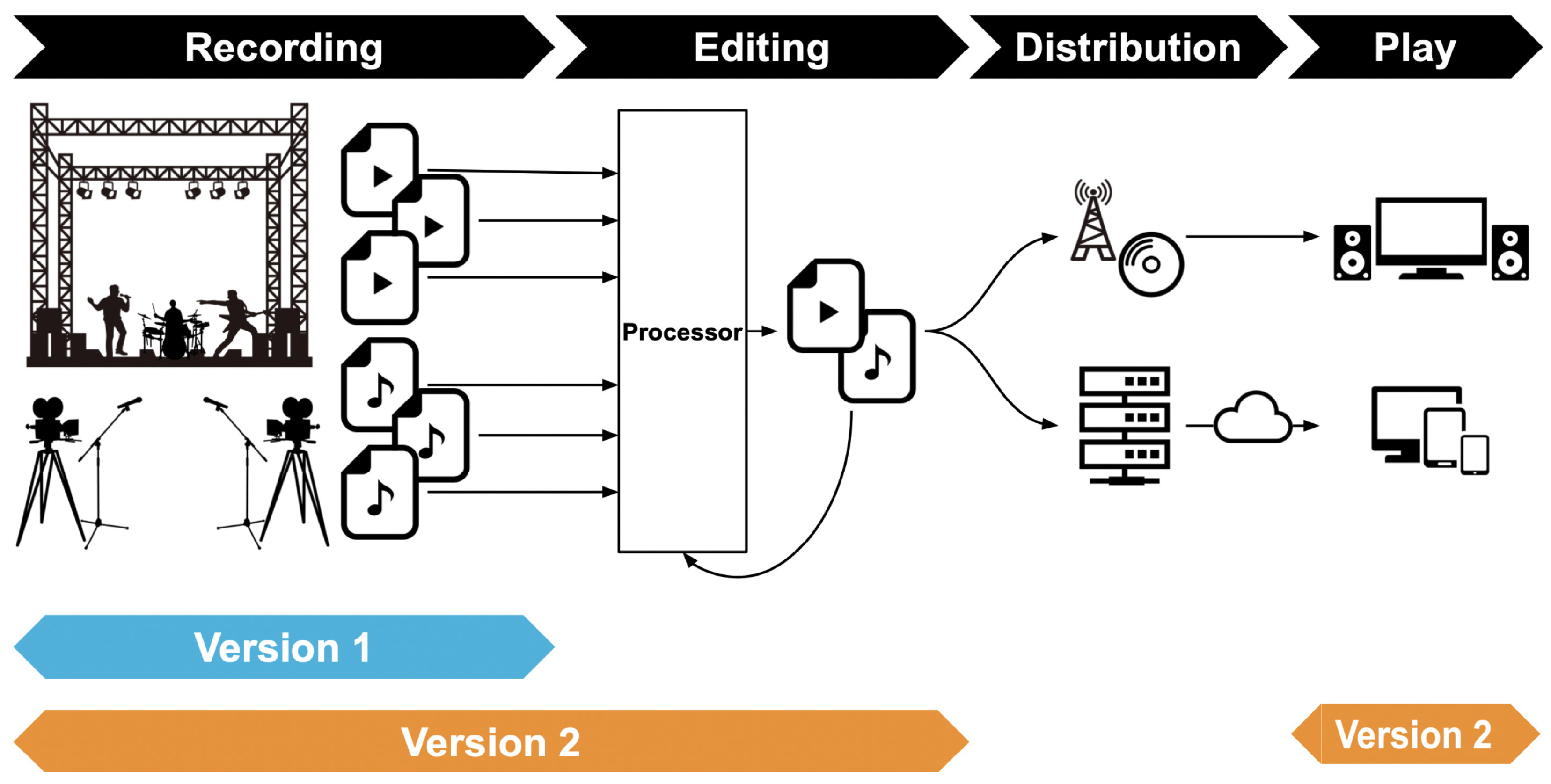
- Description of spatio-temporal media processing workflowIt is not sufficient to describe only spatio-temporal media to specify the workflow of recording, processing/editing, and playback of spatio-temporal media. It is necessary to describe the equipment and functions involved in each step of the workflow, as well as their setting information and operation details, after clarifying the input-output relationship of spatio-temporal media.
- 2.
- Semantic description with extensibilityEach spatio-temporal media and each workflow stage has its semantic information with some intention or purpose. This semantic information is fundamental and indispensable to express spatio-temporal media, but at the same time, it is not easy to define the scope of expression. Since it is not realistic to comprehensively specify this information in the SDM Ontology alone, it is appropriate to utilize external ontology to describe such information. Meanwhile, if unlimited descriptions by external ontology are allowed, the rigor of the semantic description will be compromised. It is necessary to have a system that allows descriptions utilizing external ontology in a format consistent with the design intent of the SDM Ontology.
- 3.
- Hierarchical object representationSpatio-temporal media recording is not only performed with a single piece of equipment, but with a combination of equipment. As the recording scale becomes more extensive and more people are involved, the equipment becomes more complex. The types and composition of the recorded media data also become more complex, and at the same time, the semantic information associated with the data also becomes more complex. The same situation occurs in the processing, editing, and playback phases.To cope with such a situation, it is appropriate to group devices, functions, and accompanying semantic information related to spatio-temporal media processing as necessary and represents them as hierarchical composite objects. At the same time, the spatio-temporal media itself should be described as a composite object that groups various types of spatio-temporal media and hierarchically expresses them.
- 4.
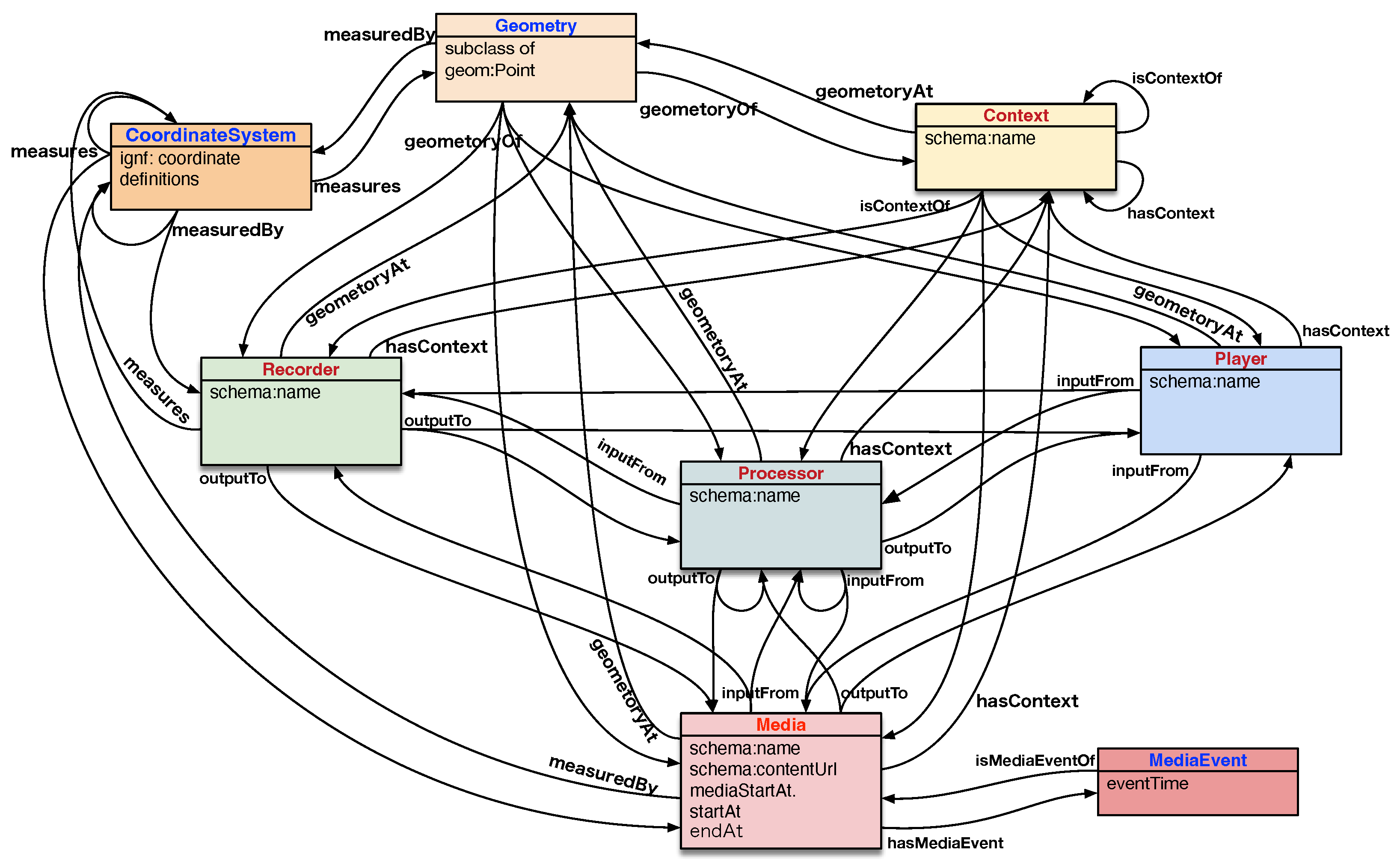
- Spatio-temporal coordinate representationSpatio-temporal coordinates are essential information in representing objects that comprise spatio-temporal media. Therefore, spatio-temporal information should be represented as a fundamental component of the SDM Ontology. Considering the diversity of objects to be handled, the spatio-temporal information they contain is also very diverse. Therefore, the SDM Ontology should be able to describe spatio-temporal information flexibly using various coordinate systems.For example, it would be natural to represent the positional information of microphones and cameras in a concert recording in the local coordinate system of the stage. Meanwhile, the location information of a concert venue is generally expressed in terms of latitude and longitude. Similarly, the time axis of video media recorded by a video camera at a concert is generally set to the origin of the recording start time. However, it is necessary to convert the origin of the time axis to correspond to the time in the concert program. Furthermore, when strict time management is required, the error of the built-in clock of the video camera may be a problem. In such cases, a mechanism to express the correspondence between the time axis in the generated video image data and the accurate time axis is required. Therefore, the spatio-temporal information must be a description that can accommodate coordinate transformation and accuracy compensation processing in the processing and editing phases.
3.2. Design Overview
3.3. Description of Class Definitions
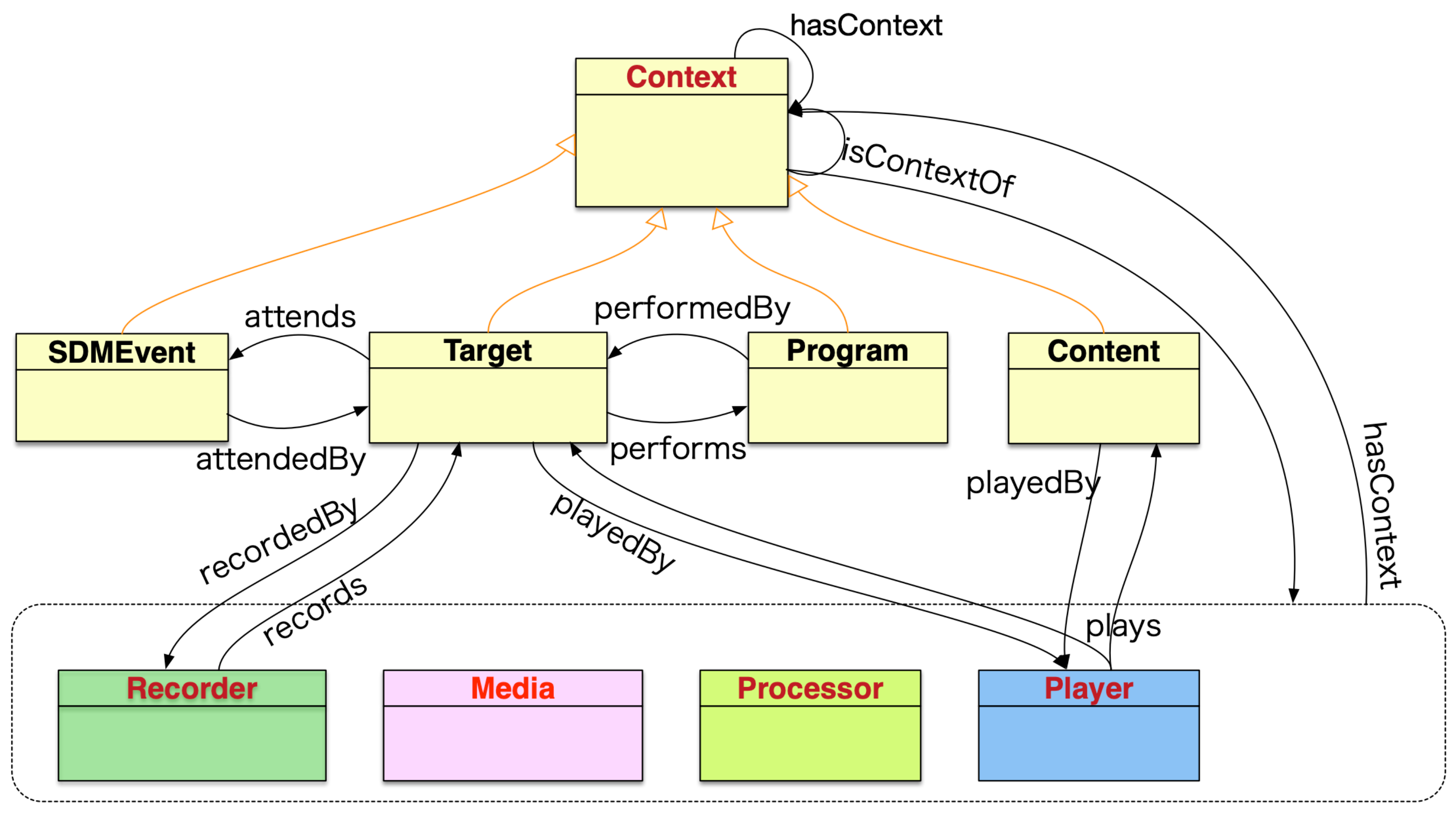
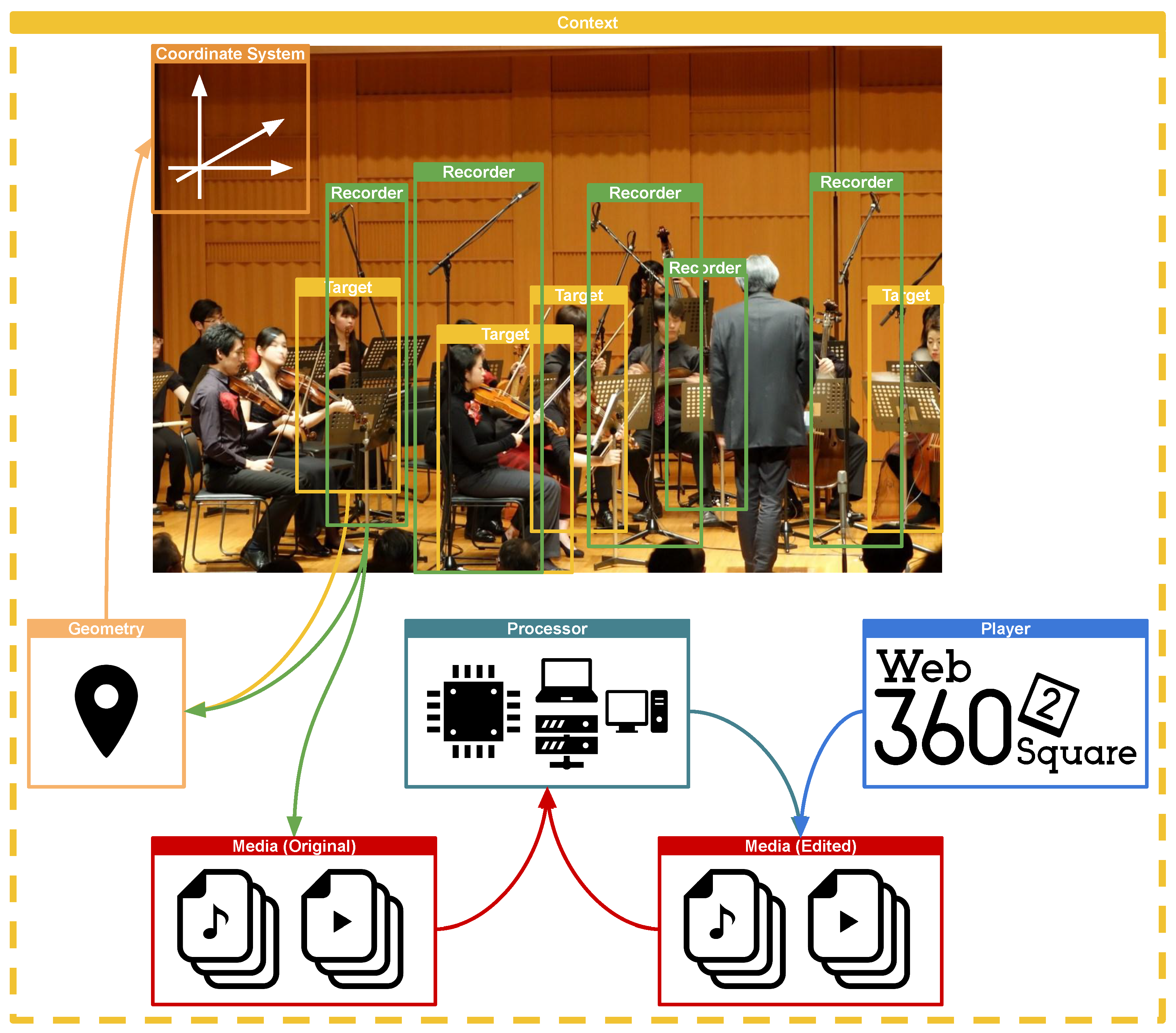
3.3.1. Context Class
- 1.
- SDMEvent subclass:This subclass represents and expresses the entire recording act. Typically, it includes the whole recording of an event, such as a concert or sporting event. By describing SDMEvent in a nested structure, events can be divided and expressed hierarchically according to the content creator’s intent. It is also possible to integrate and express multiple events.
- 2.
- Target subclass:This subclass represents the recording target. The recording target represents not only physical objects such as performers, instruments, instrument parts, and orchestras in a concert recording but also abstract objects such as the recording intention of microphones and cameras installed in various places in a concert hall.
- 3.
- Program subclass:This subclass represents the title of a song in a concert or the program of an event. These are the main attributes of the recording target.
- 4.
- Content subclass:This subclass describes the editorial intent and revision description of spatio-temporal media. Just as the SDMEvent subclass represents the act of recording, the Content subclass represents the act of editing. Typically, this subclass manages the editing history and completed content.
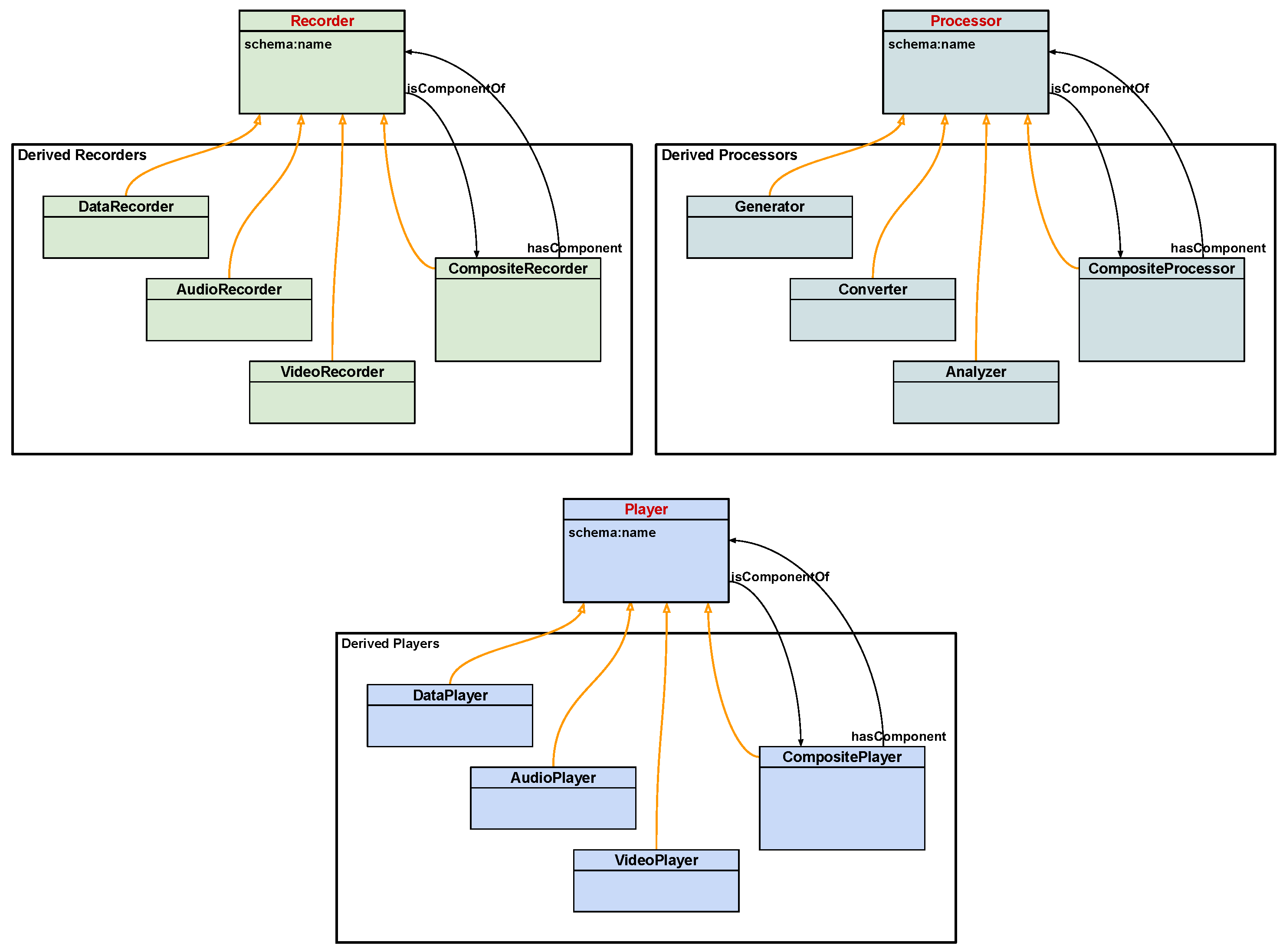
3.3.2. Recorder, Processor, Player Class
3.3.3. Recorder Class
3.3.4. Processor Class
3.3.5. Player Class
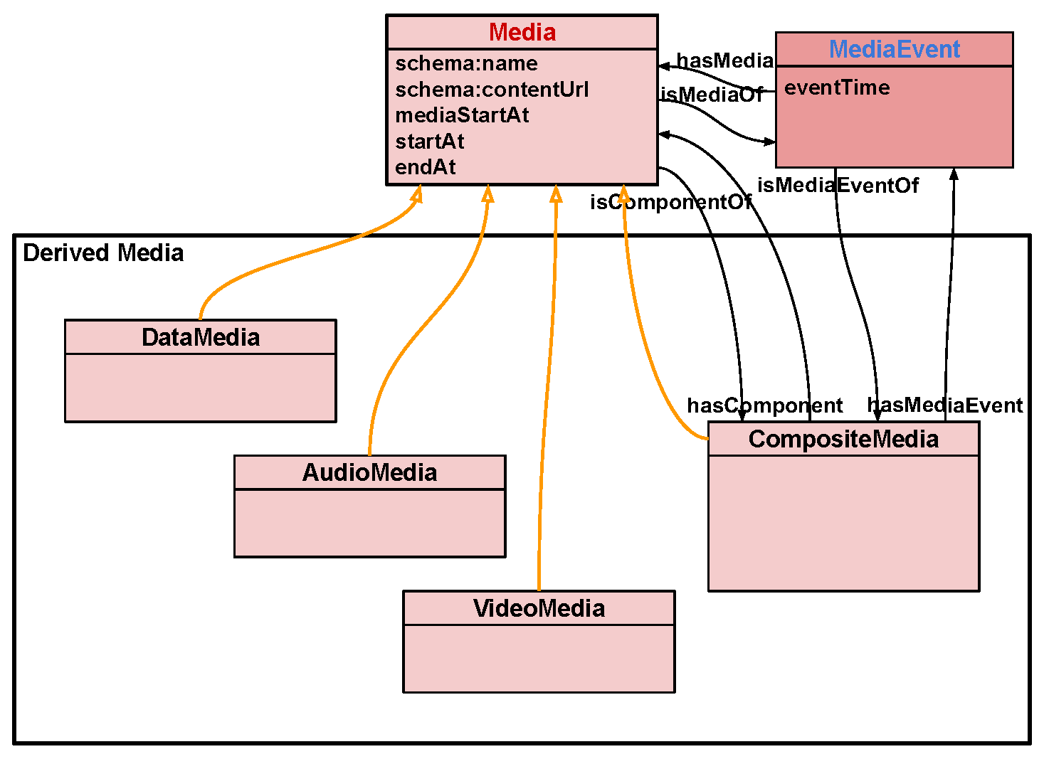
3.4. Media Class
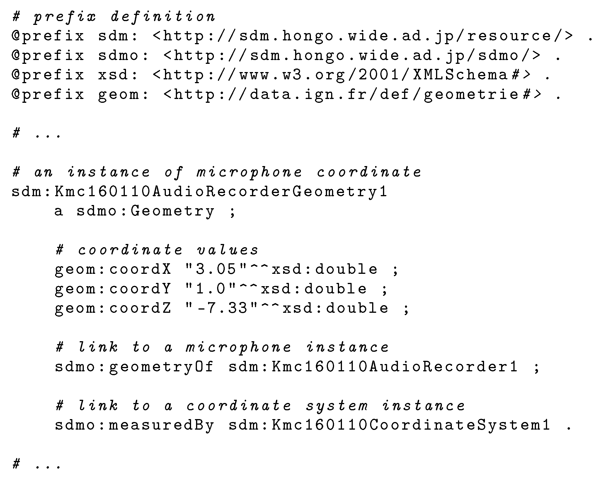
3.5. Geometry and CoordinateSystem Classes
4. Dataset
4.1. Music Events
- 1.
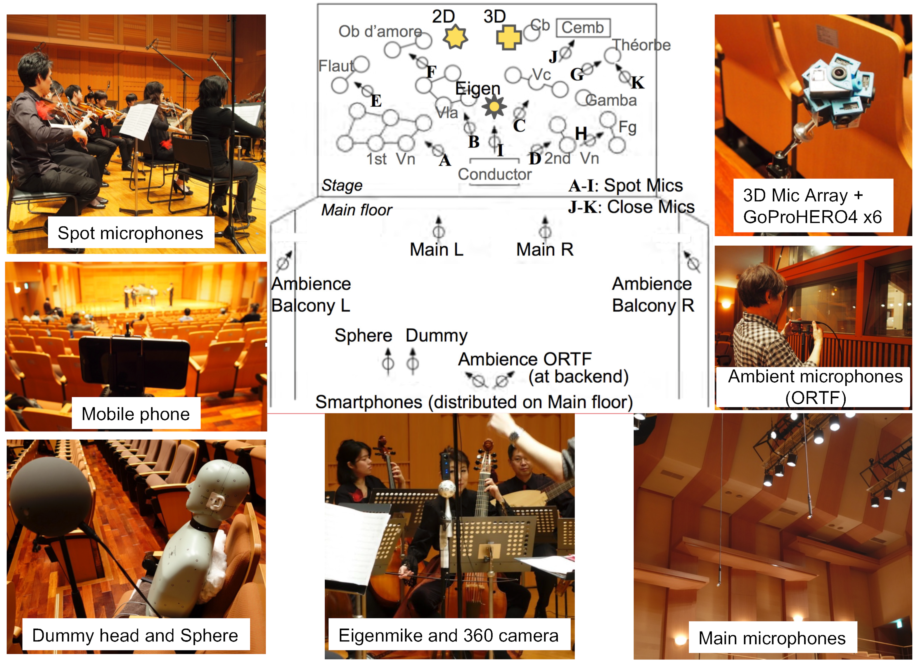
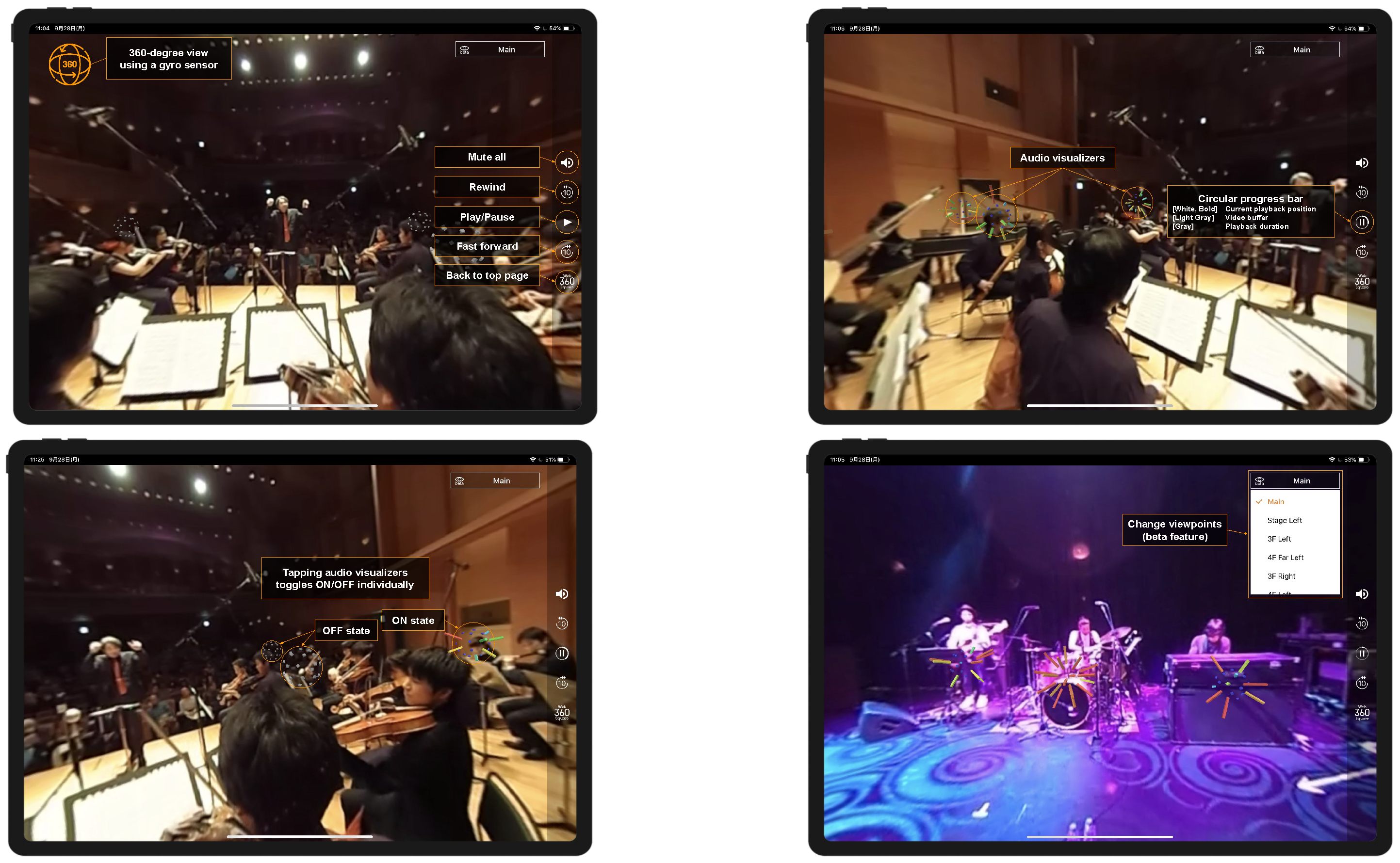
- Keio University Collegium Musicum Academy Concert Recording. This is a recording of the Keio University Collegium Musicum Academy concert held at Fujiwara Memorial Hall, Keio University Hiyoshi Campus, on 10 January 2016. The concert was performed by 24 musicians, all of them acoustic. The microphones located near the instruments recorded the performance sound of each instrument part, while the microphones located on the audience side recorded the combined sound of each instrument [52]. Figure 6 shows the arrangement of the cameras and microphones.
- 2.
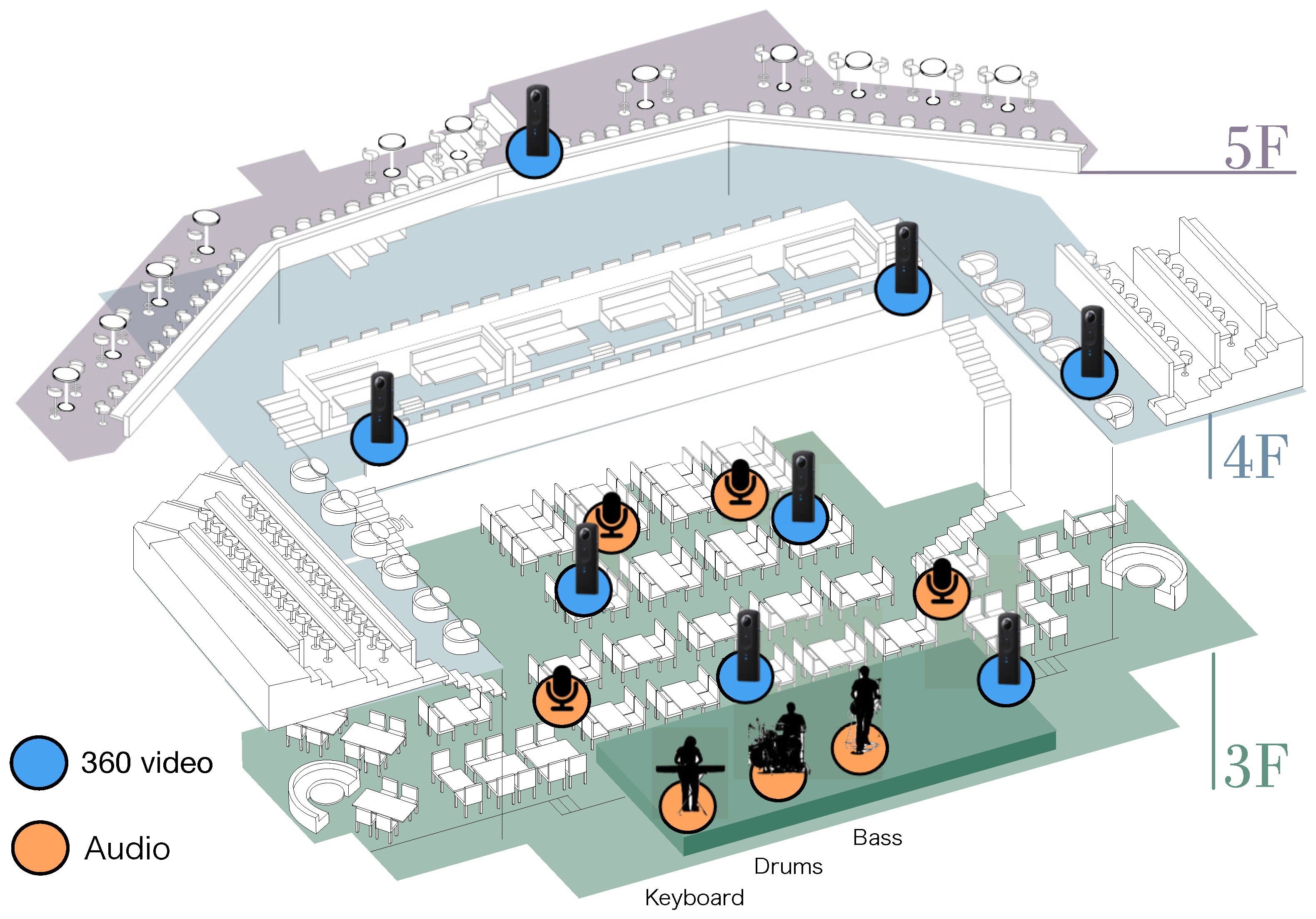
- Recording at Billboard Live Tokyo On 26 January 2017, a jazz band concert was recorded at Billboard Live Tokyo, a 300-seat venue in Roppongi Midtown, Tokyo. The band consists of three parts: drums, electric bass, and keyboard. Figure 7 shows the band composition, the location of the 360-degree camera, and the location of the microphones.The recording was made with four audience microphones in addition to the three individual instruments. The video was shot by eight cameras.
4.2. Creating Dataset
5. Web—Interactive Application Applying SDM Ontology
5.1. Design Policy
- 1.
- Data-driven applicationThe application retrieves media files and the metadata it uses from the RDF store and operates on them.
- 2.
- Web applicationWe aim for ease of use directly from a web browser without the need to install a dedicated application.
- 3.
- Video and audio playback from arbitrary viewpointsBy automatically rendering and presenting appropriate video and audio based on the 3D positional information of the viewing object, the viewer can experience video and audio playback from any viewing position or angle.
- 4.
- Interactive audio object manipulationViewer operations allow the individual access to each audio object and switch it on or off, enabling a highly flexible viewing experience based on the viewer’s interests.
- 5.
- Streaming distributionStream video via HTTP Live Streaming (HLS). By supporting streaming distribution, it is possible to shorten the waiting time before playback starts and eliminate unnecessary communication. Although MPEG DASH and MediaSouce APIs have the potential to achieve higher streaming performance than HLS, this study will use HLS in favor of its native support in Android and iOS.
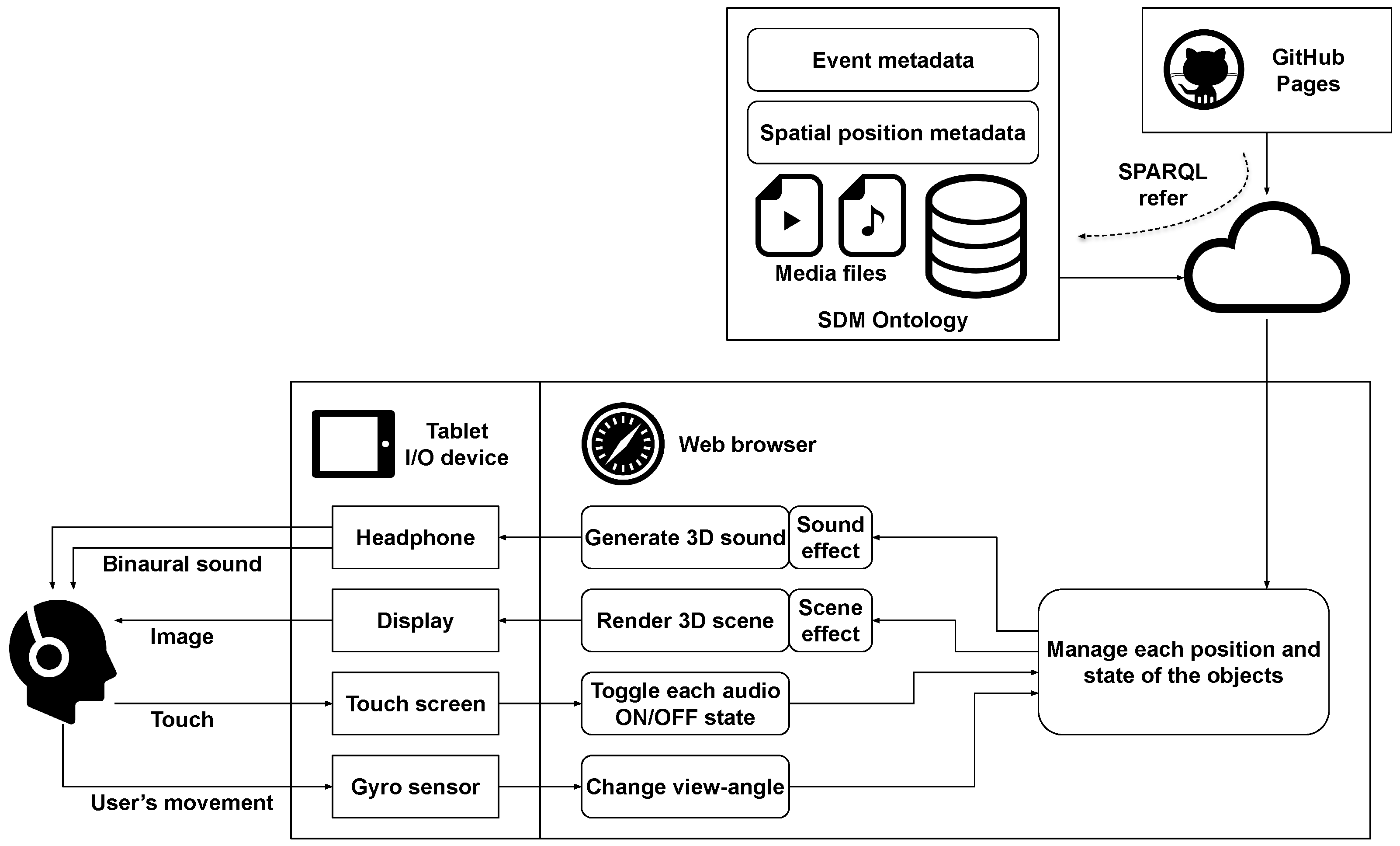
5.2. System Design
5.3. Implementation
5.3.1. Dynamic Data Acquisition by SPARQL Query
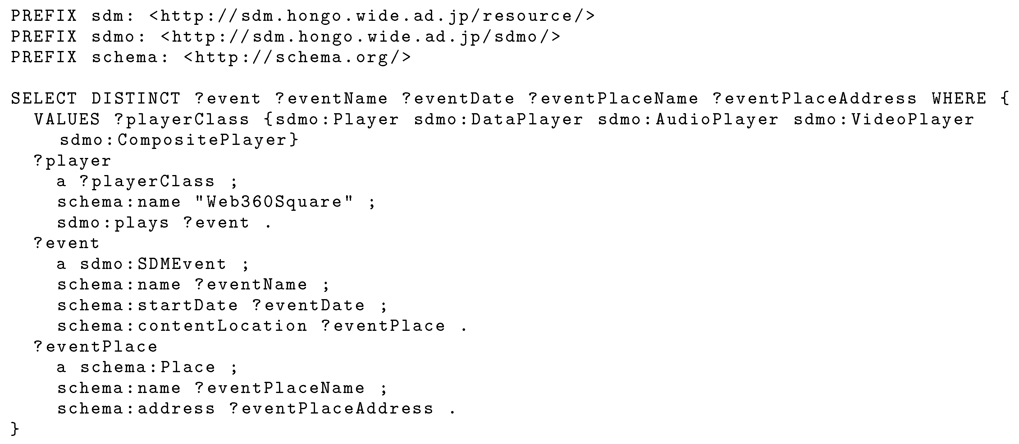
- 1.
- Event list
- 2.
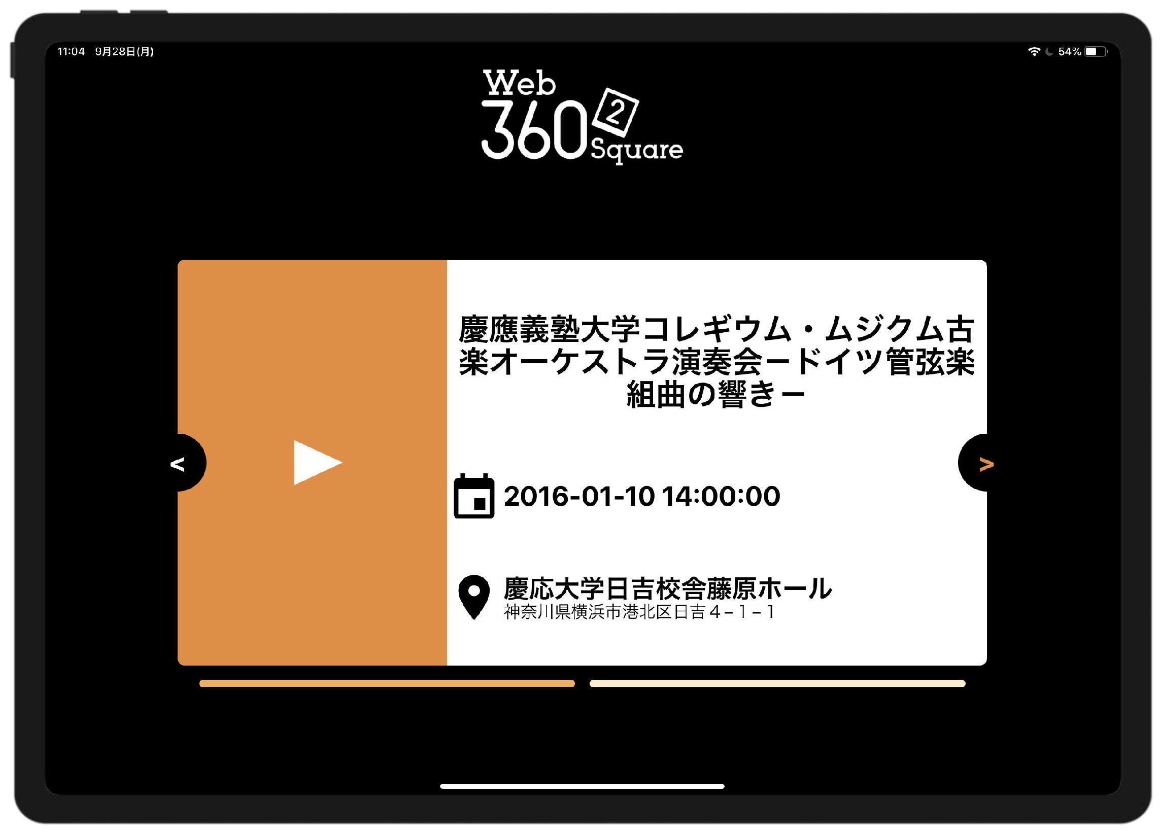
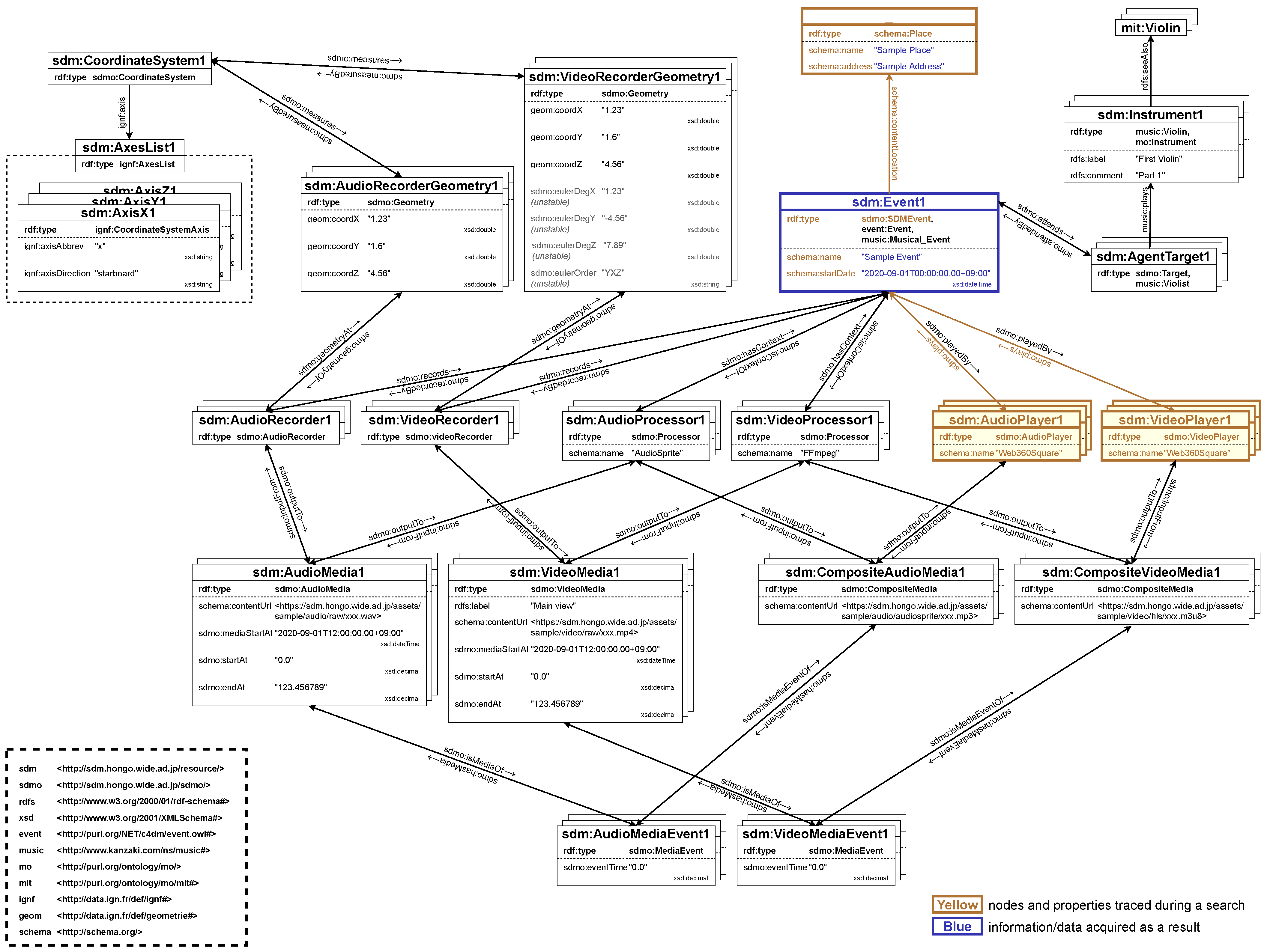
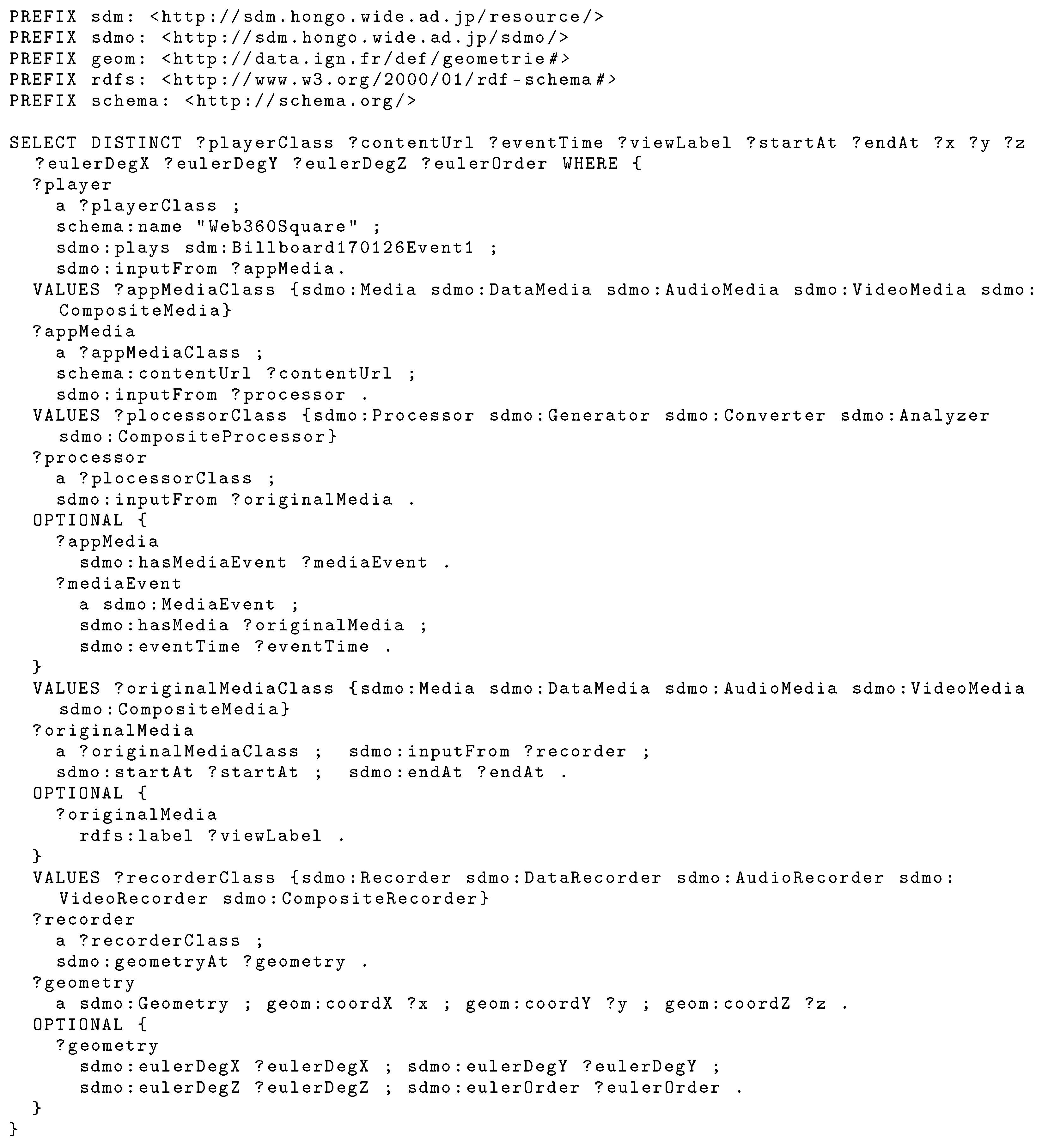
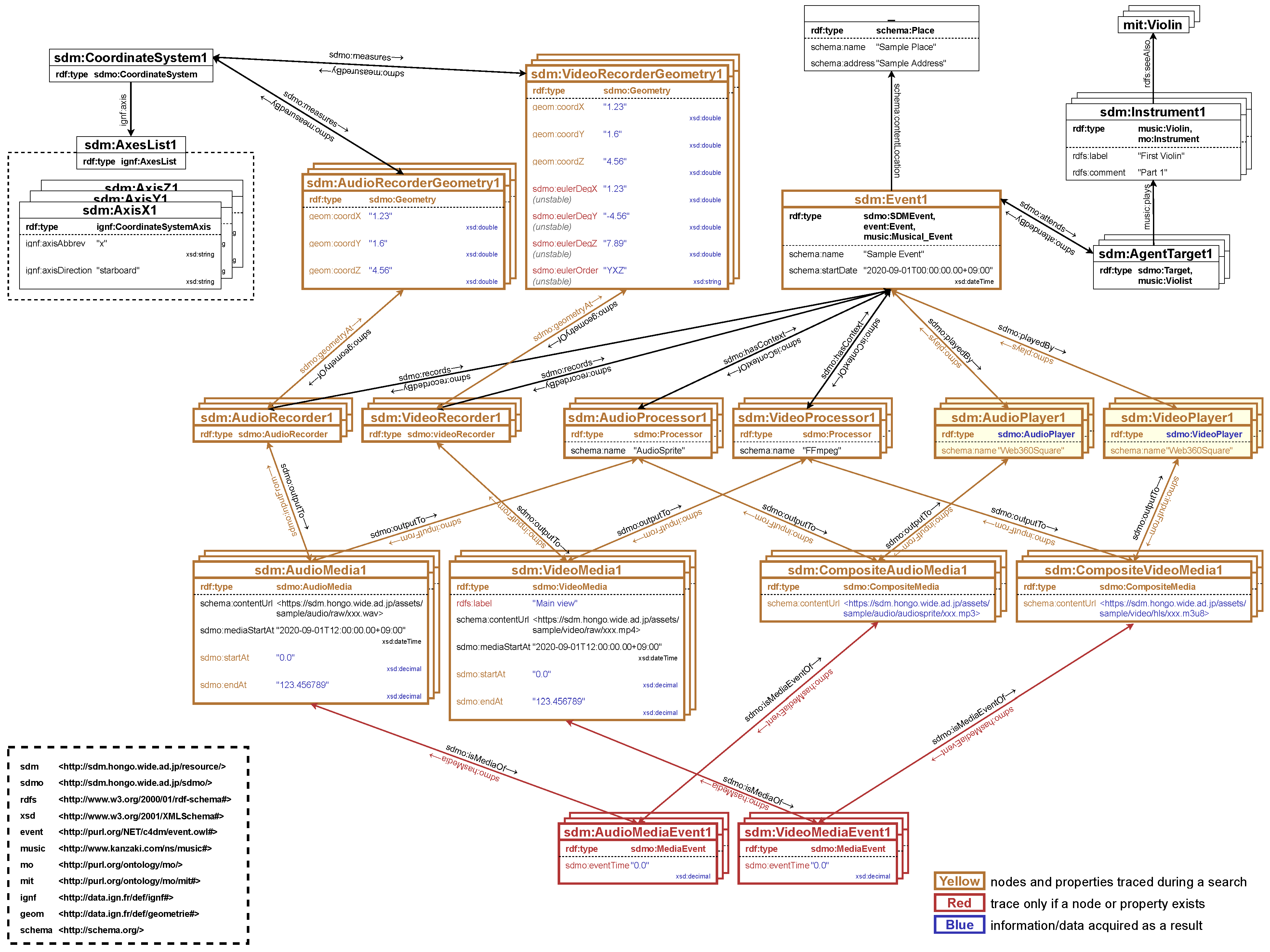
- Event resourcesWeb issues the SPARQL query in Figure 16 to obtain viewing information when an event is selected from the event selection screen. Figure 17 shows the SPARQL search path. Then it transitions to the viewing screen in Figure 12. The video and audio media files and their positional information are needed because each audio visualization object must be rendered in the correct alignment concerning the viewpoint on the viewing screen. In addition, since video and audio are independent media files, synchronization of video and audio is required. Details of the synchronization processes are described in Section 5.3.5.
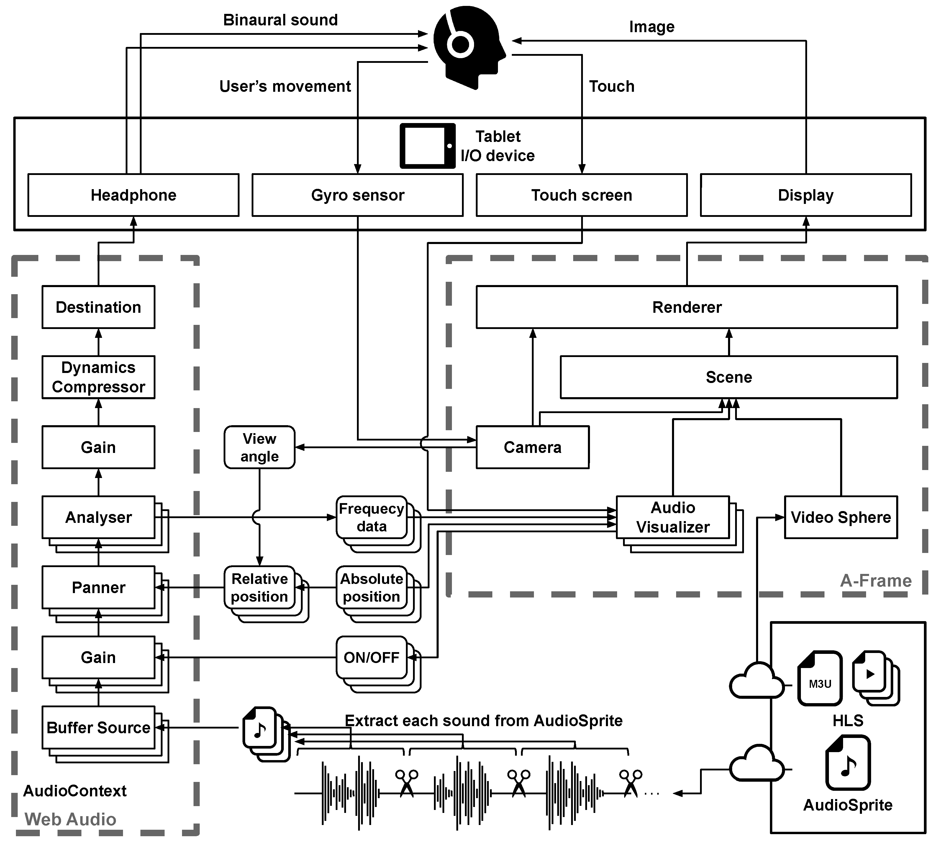
5.3.2. Video Processing Using A-Frame
5.3.3. Audio Processing Using Web Audio API
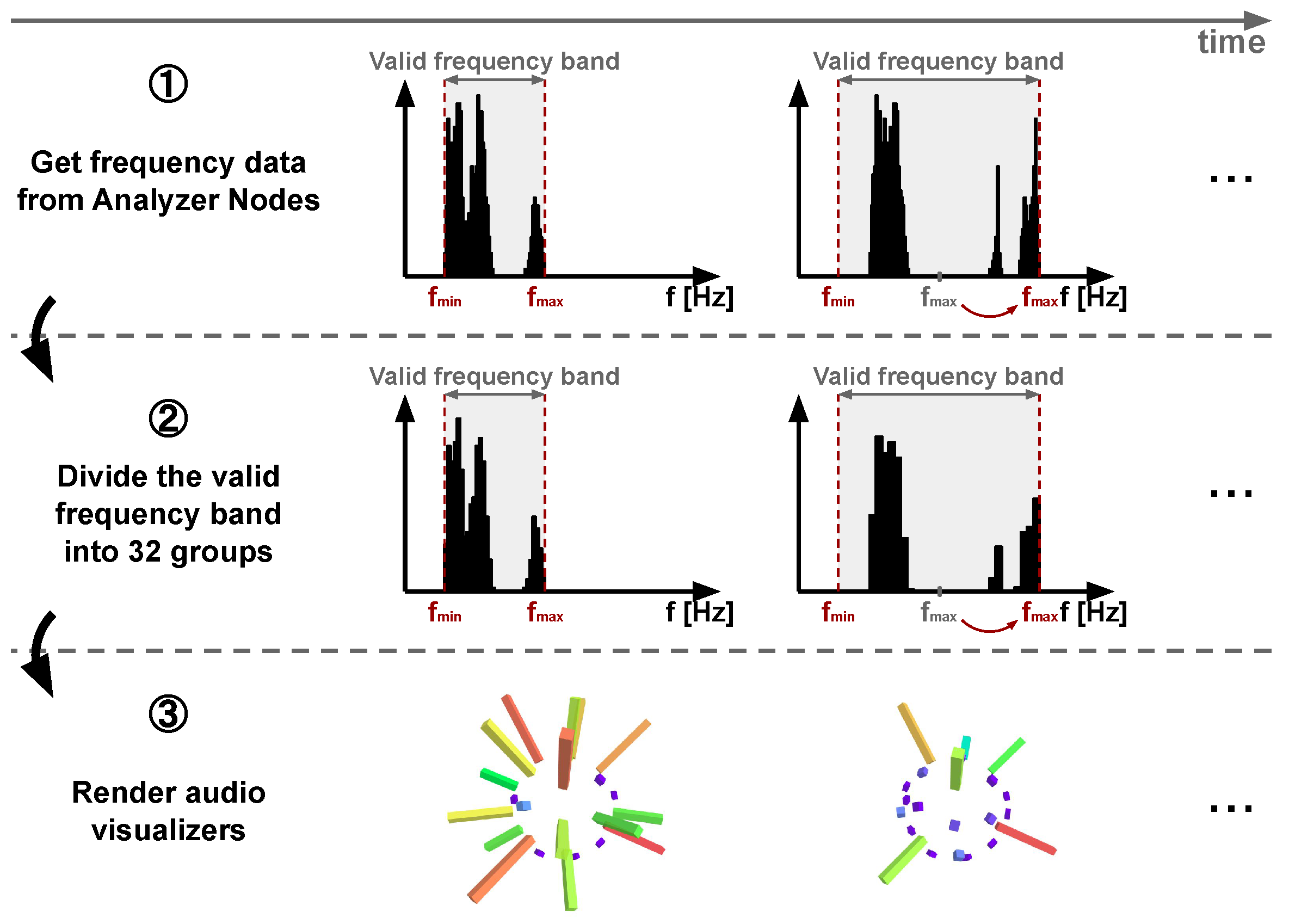
5.3.4. Visualization of Audio Objects
5.3.5. Video and Audio Synchronization
5.3.6. Moving the Viewing Position
6. Evaluation of SDM Ontology
6.1. Evaluation by Ontology Evaluation Index
- (a)
- Indicators of knowledge coverage and popularity
- Number of classesThe number of classes in the target ontology.
- Number of PropertiesThe number of properties in the target ontology.
- Number of individualsThe number of individuals in the target ontology.
- Number used in the external ontologyThe number of times the target ontology is used by external ontologies. In general, the more mature the ontology, the larger the value of this indicator.
- Number of external ontologies usedThe number of times the target ontology uses external ontologies.
- (b)
- Indicators for data structure
- Minimum number of triplesThe minimum number of triples required to describe the data for which the target ontology exists.
- Maximum number of triplesThe maximum number of triples that can be used to describe the data for which the ontology of interest exists.
6.2. Evaluation by OOPS!
- Important pitfalls
- 1.
- The prime relationships among elements are not definedThe SDM Ontology contains elemental relationships that are prime. However, the definition does not reflect them because they are not discussed in detail.
- 2.
- The subject or object of the property is not definedThese warnings occur for properties referenced using external ontologies and do not consist of a nature that should be defined within the SDM Ontology. We believe that the handling of subjects and objects that are not included in the definition of the SDM Ontology should be handled by the operational rules at the time of data production.
- 3.
- Use of recursive definitionsRecursiveness is an intentionally designed structure. We believe that operational rules should handle problems such as the circular references that may occur with recursive descriptions during data production.
- Minor pitfalls
- 1.
- Existence of independent ontology elementsThis warning occurs for class definitions with an external ontology as a superclass. This structure was intentionally designed.
- 2.
- No inverse relationship definedThis warning also occurs for properties referenced from external ontologies and is an intentionally designed structure. The properties inside the SDM Ontology have inverse relationships defined.
- 3.
- No label/annotation presentThis warning also occurs for properties referenced from external ontologies and is an intentionally designed structure.
- 4.
- Misuse of labels and annotationsThis warning occurs when there is a misuse of a label/annotation property for human reading. We believe that a warning is being generated for a label definition defined for symmetry with the definitions of other elements. However, it has not yet been determined whether it should be corrected.
6.3. SDM Ontology Promotion Activities
7. Evaluation of Web
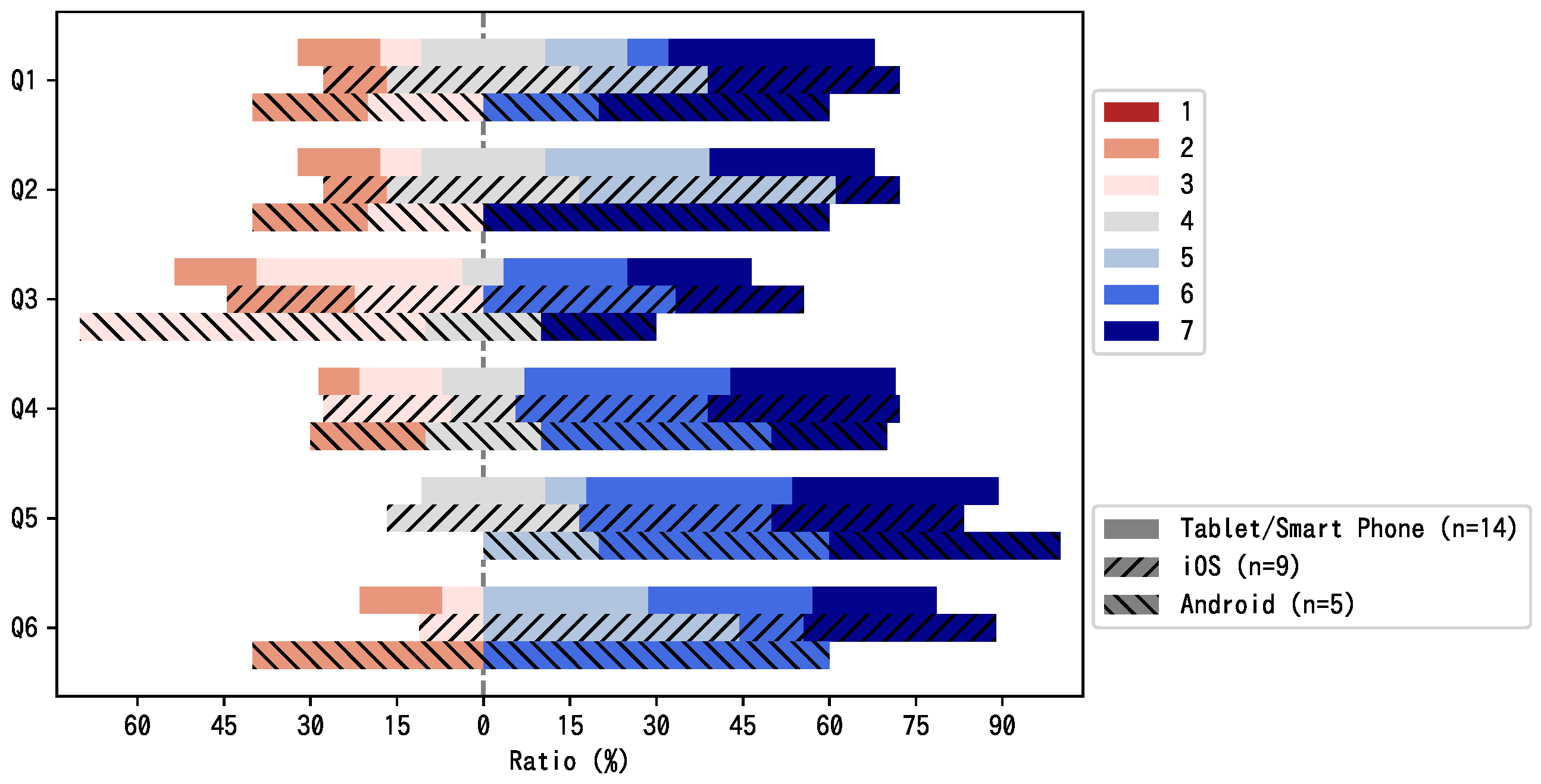
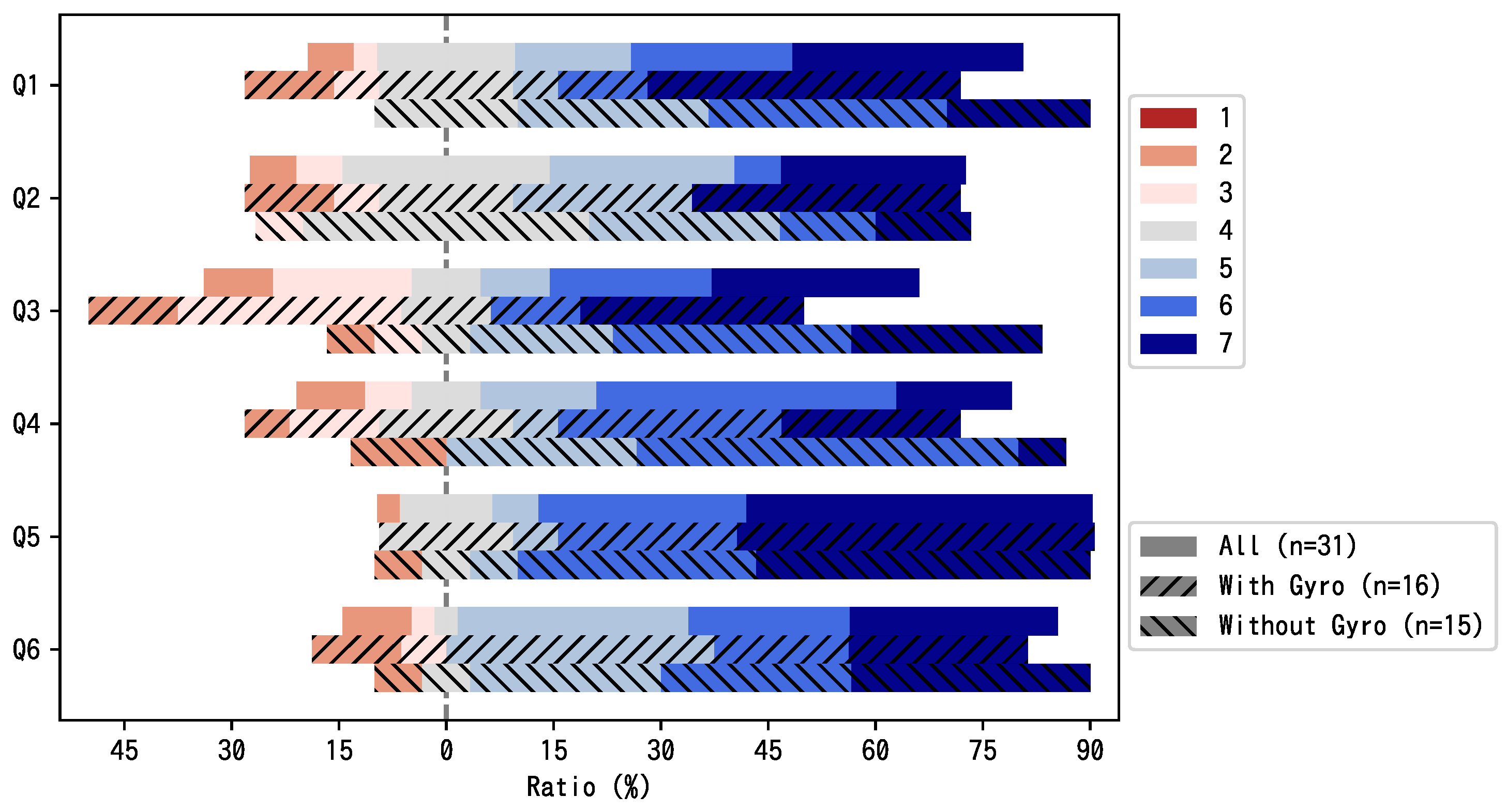
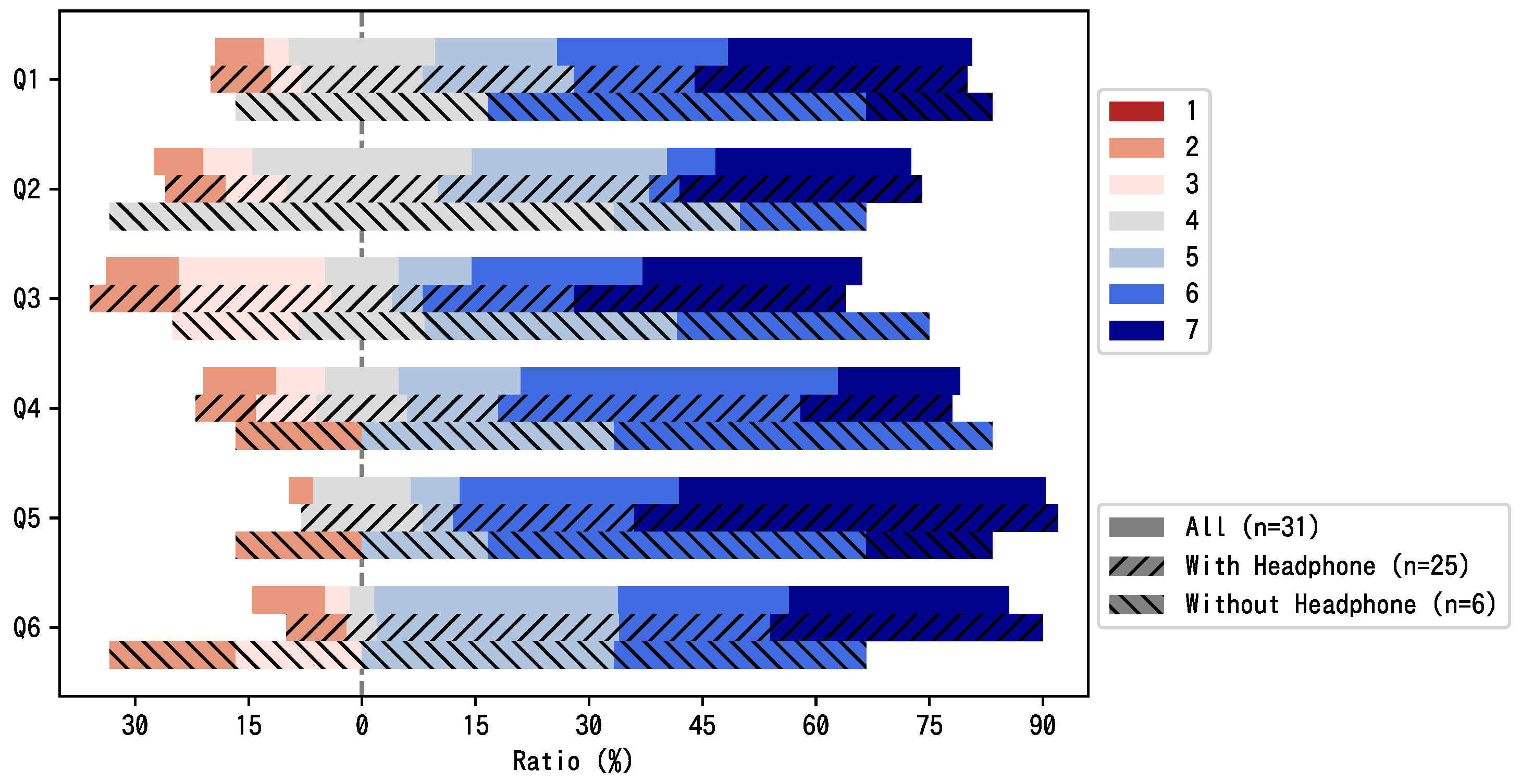
7.1. Online Survey
7.1.1. Participants
| Age Group | Number of Subjects |
| Teenagers | 1 |
| 20s | 10 |
| 30s | 2 |
| 40s | 8 |
| 50s | 7 |
| 60s or older | 3 |
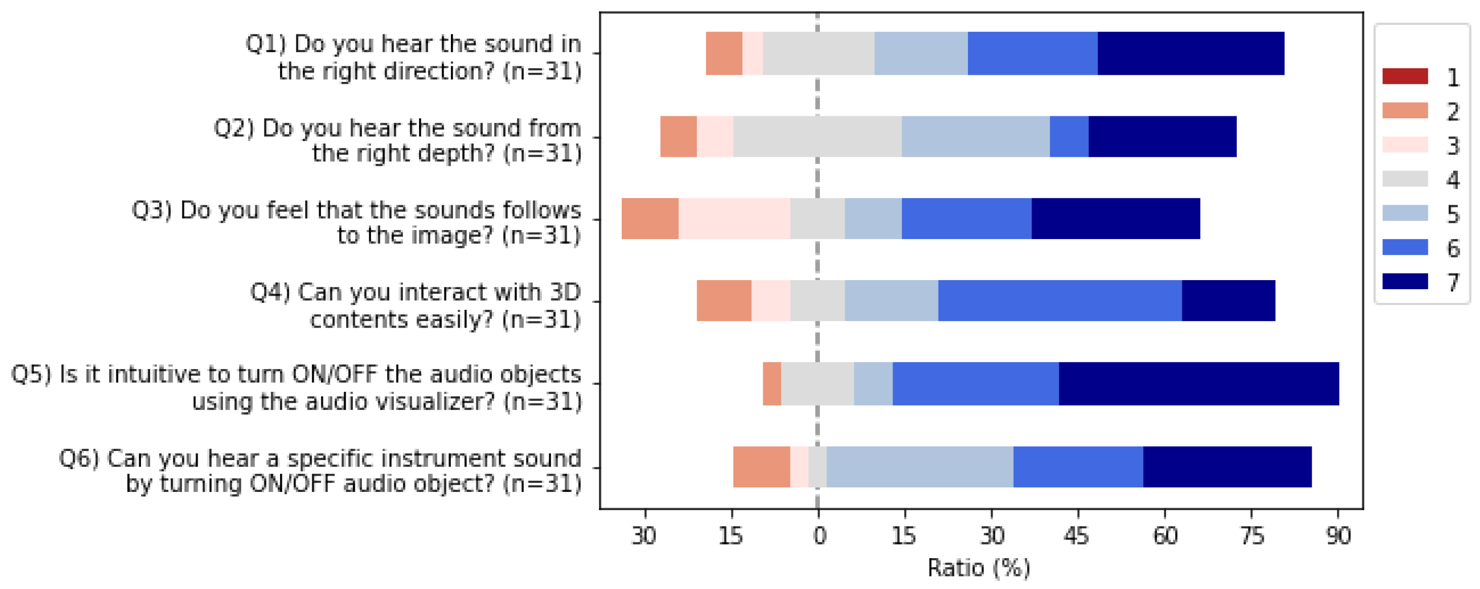
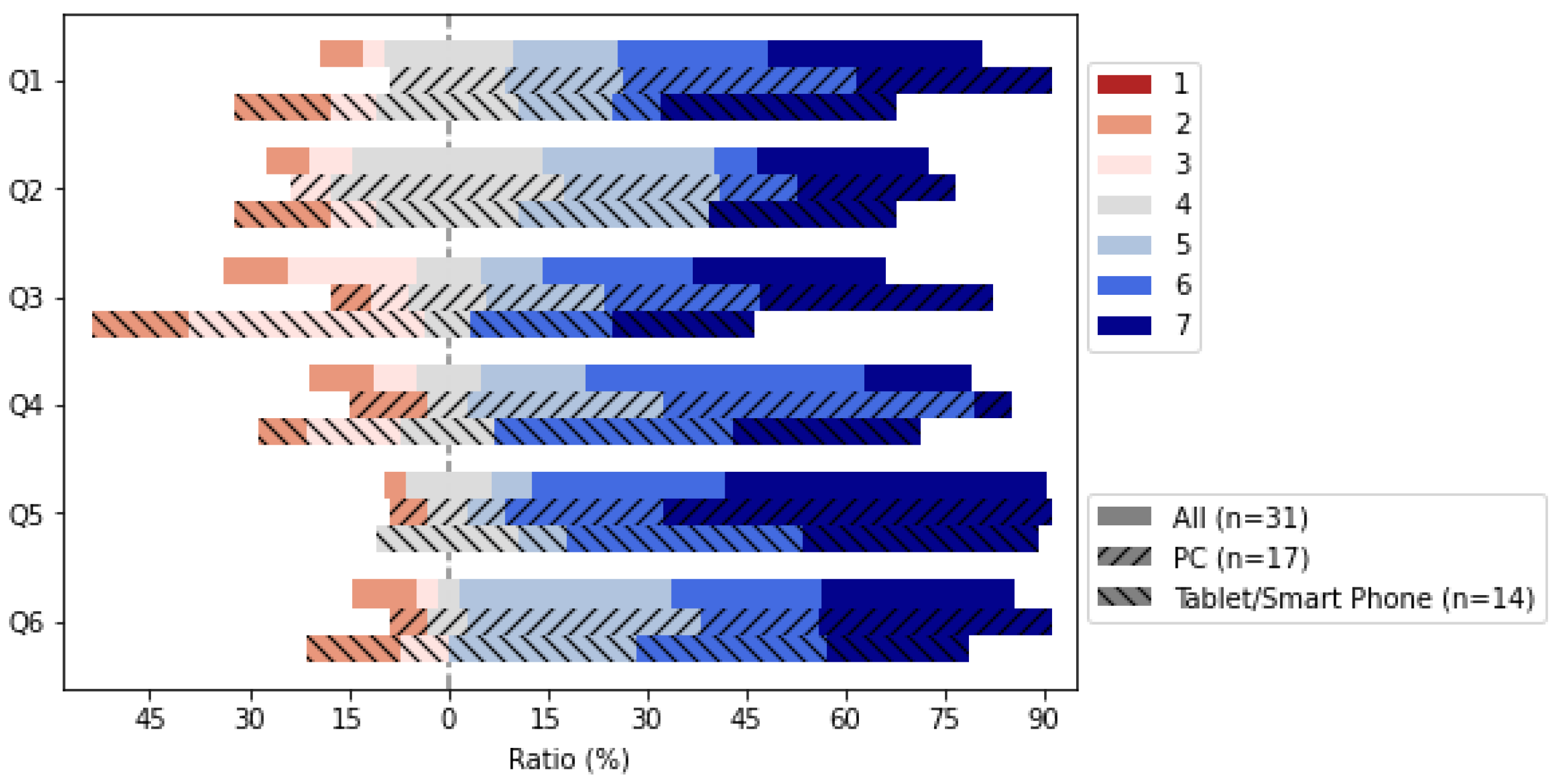
7.1.2. Questionnaire
- Q1
- Did you hear the sound from the right direction?
- Q2
- Did you hear the sound from the proper depth?
- Q3
- Do you feel that the sound follows the image?
- Q4
- Can you interact with the 3D content easily?
- Q5
- Is it intuitive to turn ON/OFF the audio objects using the audio visualizer?
- Q6
- Can you hear a specific instrument sound by turning ON/OFF audio object?
- Device name
- OS type/version
- Web browser type/version
- Network environment
- Gyro sensor use
- Headphone use
- Content viewed and experienced
7.1.3. Results
7.2. Performance Requirements Assessment
7.2.1. Required Network Performance
7.2.2. Required Rendering Performance
8. Discussion and Conclusions
Author Contributions
Funding
Data Availability Statement
Conflicts of Interest
References
- Musmann, H. Genesis of the MP3 audio coding standard. IEEE Trans. Consum. Electron. 2006, 52, 1043–1049. [Google Scholar] [CrossRef]
- Noll, P. MPEG digital audio coding. IEEE Signal Process. Mag. 1997, 14, 59–81. [Google Scholar] [CrossRef]
- Sullivan, G.J.; Ohm, J.R.; Han, W.J.; Wiegand, T. Overview of the High Efficiency Video Coding (HEVC) Standard. IEEE Trans. Circuits Syst. Video Technol. 2012, 22, 1649–1668. [Google Scholar] [CrossRef]
- Alvestrand, H.T. Overview: Real-Time Protocols for Browser-Based Applications; RFC 8825; Internet Engineering Task Force: Fremont, CA, USA, 2021. [Google Scholar] [CrossRef]
- Jesup, R.; Loreto, S.; Tuexen, M. WebRTC Data Channels; RFC 8831; Internet Engineering Task Force: Fremont, CA, USA, 2021. [Google Scholar] [CrossRef]
- Panjkov, Z.; Draskovic, S.; Pele, Z.; Katona, M. Porting, validation and verification of Dolby Pro Logic II decoder. In Proceedings of the 2011 19th Telecommunications Forum (TELFOR) Proceedings of Papers, Belgrade, Serbia, 22–24 November 2011; pp. 723–726. [Google Scholar] [CrossRef]
- Laitinen, M.V.; Pulkki, V. Binaural reproduction for Directional Audio Coding. In Proceedings of the 2009 IEEE Workshop on Applications of Signal Processing to Audio and Acoustics, New Paltz, NY, USA, 18–21 October 2009; pp. 337–340. [Google Scholar] [CrossRef]
- Brooks, F. What’s real about virtual reality? IEEE Comput. Graph. Appl. 1999, 19, 16–27. [Google Scholar] [CrossRef]
- Zyda, M. From visual simulation to virtual reality to games. Computer 2005, 38, 25–32. [Google Scholar] [CrossRef]
- Landone, C.; Sandler, M. 3-D sound systems: A computationally efficient binaural processor. In Proceedings of the IEE Colloquium on Audio and Music Technology: The Challenge of Creative DSP (Ref. No. 1998/470), London, UK, 18 November 1998; pp. 6/1–6/8. [Google Scholar] [CrossRef]
- Serafin, S.; Geronazzo, M.; Erkut, C.; Nilsson, N.C.; Nordahl, R. Sonic Interactions in Virtual Reality: State of the Art, Current Challenges, and Future Directions. IEEE Comput. Graph. Appl. 2018, 38, 31–43. [Google Scholar] [CrossRef] [PubMed]
- Kubota, A.; Smolic, A.; Magnor, M.; Tanimoto, M.; Chen, T.; Zhang, C. Multiview Imaging and 3DTV. IEEE Signal Process. Mag. 2007, 24, 10–21. [Google Scholar] [CrossRef]
- Fitzpatrick, W.; Wickert, M.; Semwal, S. 3D sound imaging with head tracking. In Proceedings of the 2013 IEEE Digital Signal Processing and Signal Processing Education Meeting (DSP/SPE), Napa, CA, USA, 11–14 August 2013; pp. 216–221. [Google Scholar] [CrossRef]
- Salisbury, K.; Conti, F.; Barbagli, F. Haptic rendering: Introductory concepts. IEEE Comput. Graph. Appl. 2004, 24, 24–32. [Google Scholar] [CrossRef] [PubMed]
- Narumi, T.; Kajinami, T.; Nishizaka, S.; Tanikawa, T.; Hirose, M. Pseudo-gustatory display system based on cross-modal integration of vision, olfaction and gustation. In Proceedings of the 2011 IEEE Virtual Reality Conference, Singapore, 19–23 March 2011; pp. 127–130. [Google Scholar] [CrossRef]
- Tsukada, M.; Ogawa, K.; Ikeda, M.; Sone, T.; Niwa, K.; Saito, S.; Kasuya, T.; Sunahara, H.; Esaki, H. Software defined media: Virtualization of audio-visual services. In Proceedings of the 2017 IEEE International Conference on Communications (ICC), Paris, France, 21–25 May 2017; pp. 1–7. [Google Scholar]
- Atarashi, R.; Sone, T.; Komohara, Y.; Tsukada, M.; Kasuya, T.; Okumura, H.; Ikeda, M.; Esaki, H. The software defined media ontology for music events. In Proceedings of the 1st International Workshop on Semantic Applications for Audio and Music, Monterey, CA, USA, 9 October 2018; pp. 15–23. [Google Scholar]
- Raimond, Y.; Abdallah, S.A.; Sandler, M.B.; Giasson, F. The Music Ontology. ISMIR 2007, 2007, 8. [Google Scholar]
- Raimond, Y.; Gängler, T.; Giasson, F.; Jacobson, K.; Fazekas, G.; Reinhardt, S.; Passant, A. The Music Ontology. Available online: http://musicontology.com/ (accessed on 26 April 2020).
- Raimond, Y.; Abdallah, S. The Timeline Ontology. Available online: http://purl.org/NET/c4dm/timeline.owl (accessed on 26 April 2020).
- Raimond, Y.; Abdallah, S. The Event Ontology. Available online: http://purl.org/NET/c4dm/event.owl (accessed on 26 April 2020).
- Davis, I.; Newman, R. Expression of Core FRBR Concepts in RDF. Available online: https://vocab.org/frbr/core (accessed on 26 April 2020).
- Brickley, D.; Miller, L. FOAF Vocabulary Specification 0.99. Available online: http://xmlns.com/foaf/spec/ (accessed on 26 April 2020).
- Fazekas, G.; Sandler, M.B. The Studio Ontology Framework. In Proceedings of the ISMIR, Miami, FL, USA, 24–28 October 2011; pp. 471–476. [Google Scholar]
- Wilmering, T.; Fazekas, G.; Sandler, M.B. The Audio Effects Ontology. In Proceedings of the ISMIR, Curitiba, Brazil, 4–8 November 2013; pp. 215–220. [Google Scholar]
- Wilmering, T.; Fazekas, G. The Audio Effect Ontology. Available online: https://w3id.org/aufx/ontology/1.0# (accessed on 26 April 2020).
- Kolozali, S.; Barthet, M.; Fazekas, G.; Sandler, M.B. Knowledge Representation Issues in Musical Instrument Ontology Design. In Proceedings of the ISMIR, Miami, FL, USA, 24–28 October 2011; pp. 465–470. [Google Scholar]
- Kolozali, S.; Fazekas, G.; Barthet, M.; Sandler, M. A framework for automatic ontology generation based on semantic audio analysis. In Proceedings of the Audio Engineering Society Conference: 53rd International Conference: Semantic Audio, London, UK, 26–29 January 2014. [Google Scholar]
- Allik, A.; Fazekas, G.; Sandler, M.B. An Ontology for Audio Features. In Proceedings of the ISMIR, New York City, NY, USA, 7–11 August 2016; pp. 73–79. [Google Scholar]
- Fazekas, G.; Allik, A. Audio Features Ontology. Available online: https://semantic-audio.github.io/afo/ (accessed on 26 April 2020).
- Ceriani, M.; Fazekas, G. Audio Commons ontology: A data model for an audio content ecosystem. In The Semantic Web—ISWC 2018, Proceedings of the 17th International Semantic Web Conference, Monterey, CA, USA, 8–12 October 2018; Springer: Berlin/Heidelberg, Germany, 2018; pp. 20–35. [Google Scholar]
- Fazekas, G.; Ceriani, M. The Audio Commons Ontology. Available online: https://w3id.org/ac-ontology/aco# (accessed on 26 April 2020).
- Turchet, L.; Antoniazzi, F.; Viola, F.; Giunchiglia, F.; Fazekas, G. The Internet of Musical Things Ontology. J. Web Semant. 2020, 60, 100548. [Google Scholar] [CrossRef]
- Antoniazzi, F. Internet of Musical Things Ontology (IoMusT). Available online: https://fr4ncidir.github.io/IoMusT/ (accessed on 26 April 2020).
- Chang, S.F.; Sikora, T.; Purl, A. Overview of the MPEG-7 standard. IEEE Trans. Circuits Syst. Video Technol. 2001, 11, 688–695. [Google Scholar] [CrossRef]
- Man, J.F.; Yang, L.M.; Wu, Z.H.; Xu, G.W. Research on multimedia ontology bridging “semantic gap” between perceivable world and conceptual world. In Proceedings of the 2008 First IEEE International Conference on Ubi-Media Computing, Lanzhou, China, 31 July–1 August 2008; pp. 100–105. [Google Scholar] [CrossRef]
- Mallik, A.; Ghosh, H.; Chaudhury, S.; Harit, G. MOWL: An ontology representation language for web-based multimedia applications. ACM Trans. Multimed. Comput. Commun. Appl. 2013, 10, 1–21. [Google Scholar] [CrossRef]
- Sujal Subhash Wattamwar, H.G. Spatio-temporal query for multimedia databases. In Proceedings of the 2nd ACM workshop on Multimedia Semantics, International Multimedia Conference, Vancouver, Canada, 31 October 2008; pp. 48–55. [Google Scholar]
- Choi, C.; Wang, T.; Esposito, C.; Gupta, B.B.; Lee, K. Sensored Semantic Annotation for Traffic Control Based on Knowledge Inference in Video. IEEE Sens. J. 2021, 21, 11758–11768. [Google Scholar] [CrossRef]
- Duckham, M.; Gabela, J.; Kealy, A.; Khan, M.; Legg, J.; Moran, B.; Rumi, S.K.; Salim, F.D.; Sharmeen, S.; Tao, Y.; et al. Explainable spatiotemporal reasoning for geospatial intelligence applications. Trans. GIS 2022, 26, 2455–2479. [Google Scholar] [CrossRef]
- 23008-3:2019; Information Iechnology—High Efficiency Coding and Media Delivery in Heterogeneous Environments—Part 3: 3D Audio. ISO; IEC: Washington, DC, USA, 2019.
- Beack, S.; Sung, J.; Seo, J.; Lee, T. MPEG Surround Extension Technique for MPEG-H 3D Audio. ETRI J. 2016, 38, 829–837. [Google Scholar] [CrossRef]
- Dolby Laboratories. Dolby Atmos® Specifications; Dolby Laboratories: San Francisco, CA, USA, 2015; Isuue 3. [Google Scholar]
- Dolby Laboratories. Dolby Atmos® Home Theater Installation Guidelines; Technical Report; Dolby Laboratories: San Francisco, CA, USA, 2018. [Google Scholar]
- DTS, Inc. Home Theater Sound Gets Real. Available online: https://dts.com/dtsx (accessed on 5 September 2020).
- Auro Technologies. AUROMAX® Next Generation Immersive Sound System; Technical report; Auro Technologies: Ayer Keroh, Malaysia, 2015. [Google Scholar]
- Herre, J.; Hilpert, J.; Kuntz, A.; Plogsties, J. MPEG-H 3D audio—The new standard for coding of immersive spatial audio. IEEE J. Sel. Top. Signal Process. 2015, 9, 770–779. [Google Scholar] [CrossRef]
- Ricoh Company, Ltd. 360-Degree Camera RICOH THETA. Available online: https://theta360.com/ (accessed on 5 September 2020).
- Kasuya, T.; Tsukada, M.; Komohara, Y.; Takasaka, S.; Mizuno, T.; Nomura, Y.; Ueda, Y.; Esaki, H. LiVRation: Remote VR live platform with interactive 3D audio-visual service. In Proceedings of the 2019 IEEE Games, Entertainment, Media Conference (GEM), New Haven, CT, USA, 18–21 June 2019; pp. 1–7. [Google Scholar]
- Wang, R.; Peethambaran, J.; Chen, D. LiDAR Point Clouds to 3-D Urban Models: A Review. IEEE J. Sel. Top. Appl. Earth Obs. Remote Sens. 2018, 11, 606–627. [Google Scholar] [CrossRef]
- Turner, E.; Cheng, P.; Zakhor, A. Fast, Automated, Scalable Generation of Textured 3D Models of Indoor Environments. IEEE J. Sel. Top. Signal Process. 2015, 9, 409–421. [Google Scholar] [CrossRef]
- Ikeda, M.; Sone, T.; Niwa, K.; Saito, S.; Tsukada, M.; Esaki, H. New recording application for software defined media. In Proceedings of the Audio Engineering Society Convention 141, Los Angeles, CA, USA, 29 September–2 October 2016. [Google Scholar]
- Kato, S.; Ikeda, T.; Kawamorita, M.; Tsukada, M.; Esaki, H. Web3602: An Interactive Web Application for viewing 3D Audio-visual Contents. In Proceedings of the 17th Sound and Music Computing Conference (SMC), Torino, Italy, 24–26 June 2020. [Google Scholar]
- Fernández, M.; Overbeeke, C.; Sabou, M.; Motta, E. What makes a good ontology? A case-study in fine-grained knowledge reuse. In The Semantic Web, Proceedings of the Fourth Asian Conference, ASWC 2009, Shanghai, China, 6–9 December 2009; Springer: Berlin/Heidelberg, Germany, 2009; pp. 61–75. [Google Scholar]
- Poveda-Villalón, M.; Gómez-Pérez, A.; Suárez-Figueroa, M.C. OOPS! (OntOlogy Pitfall Scanner!): An On-line Tool for Ontology Evaluation. Int. J. Semant. Web Inf. Syst. 2014, 10, 7–34. [Google Scholar] [CrossRef]
- Garijo, D. WIDOCO: A wizard for documenting ontologies. In The Semantic Web—ISWC 2017, Proceedings of the 16th International Semantic Web Conference, Vienna, Austria, 21–25 October 2017; Springer: Cham, Switzerland, 2017; pp. 94–102. [Google Scholar]
- Mian, A.; Bennamoun, M.; Owens, R. Three-Dimensional Model-Based Object Recognition and Segmentation in Cluttered Scenes. IEEE Trans. Pattern Anal. Mach. Intell. 2006, 28, 1584–1601. [Google Scholar] [CrossRef] [PubMed]
- Maturana, D.; Scherer, S. VoxNet: A 3D Convolutional Neural Network for real-time object recognition. In Proceedings of the 2015 IEEE/RSJ International Conference on Intelligent Robots and Systems (IROS), Hamburg, Germany, 28 September–2 October 2015; pp. 922–928. [Google Scholar] [CrossRef]


| Index | Value |
|---|---|
| Number of classes | 30 |
| Number of properties | 31 |
| - Object properties | 23 |
| - Data properties | 8 |
| Number of individuals | 0 |
| Number of external ontologies using it | 0 |
| Number of external ontologies used | 3 |
| - Percentage of external classes | 10.0% |
| - Percentage of external properties | 16.1% |
| N | Q1 | Q2 | Q3 | Q4 | Q5 | Q6 | |
|---|---|---|---|---|---|---|---|
| PC | 17 | 5.77 | 5.12 | 5.53 | 5.18 | 6.18 | 5.65 |
| Smartphone | 14 | 5.00 | 4.79 | 4.43 | 5.29 | 5.86 | 5.14 |
| p-value | 0.19 | 0.57 | 0.10 | 0.85 | 0.49 | 0.38 | |
| iOS | 9 | 5.00 | 4.56 | 4.67 | 5.44 | 5.67 | 5.56 |
| Android | 5 | 5.00 | 5.20 | 4.00 | 5.00 | 6.20 | 4.40 |
| p-value | 1.00 | 0.61 | 0.54 | 0.69 | 0.38 | 0.33 | |
| Gyro | 16 | 5.31 | 5.06 | 4.63 | 5.19 | 6.06 | 5.19 |
| NoGyro | 16 | 5.53 | 4.87 | 5.47 | 5.27 | 6.00 | 5.67 |
| p-value | 0.69 | 0.72 | 0.19 | 0.89 | 0.90 | 0.39 | |
| Headphone | 25 | 5.40 | 5.08 | 5.08 | 5.28 | 6.20 | 5.64 |
| No Headphones | 6 | 5.50 | 4.50 | 4.83 | 5.00 | 5.33 | 4.50 |
| p-value | 0.87 | 0.24 | 0.70 | 0.70 | 0.29 | 0.16 | |
Disclaimer/Publisher’s Note: The statements, opinions and data contained in all publications are solely those of the individual author(s) and contributor(s) and not of MDPI and/or the editor(s). MDPI and/or the editor(s) disclaim responsibility for any injury to people or property resulting from any ideas, methods, instructions or products referred to in the content. |
© 2023 by the authors. Licensee MDPI, Basel, Switzerland. This article is an open access article distributed under the terms and conditions of the Creative Commons Attribution (CC BY) license (https://creativecommons.org/licenses/by/4.0/).
Share and Cite
Sone, T.; Kato, S.; Atarashi, R.; Nakazato, J.; Tsukada, M.; Esaki, H. An Ontology for Spatio-Temporal Media Management and an Interactive Application. Future Internet 2023, 15, 225. https://doi.org/10.3390/fi15070225
Sone T, Kato S, Atarashi R, Nakazato J, Tsukada M, Esaki H. An Ontology for Spatio-Temporal Media Management and an Interactive Application. Future Internet. 2023; 15(7):225. https://doi.org/10.3390/fi15070225
Chicago/Turabian StyleSone, Takuro, Shin Kato, Ray Atarashi, Jin Nakazato, Manabu Tsukada, and Hiroshi Esaki. 2023. "An Ontology for Spatio-Temporal Media Management and an Interactive Application" Future Internet 15, no. 7: 225. https://doi.org/10.3390/fi15070225
APA StyleSone, T., Kato, S., Atarashi, R., Nakazato, J., Tsukada, M., & Esaki, H. (2023). An Ontology for Spatio-Temporal Media Management and an Interactive Application. Future Internet, 15(7), 225. https://doi.org/10.3390/fi15070225