

Towards a Reference Architecture for Cargo Ports


Abstract
1. Introduction
- -
- A set of process/structure patterns that describe the functional aspects of a reference architecture for cargo ports. These patterns describe semantic aspects found in any cargo port and can be adapted or extended to describe other CPSs.
- -
- A decomposition of the cargo port process patterns into use cases that describe its actor interactions with the system. The use cases are dynamic models that complement the structural models of the port.
- -
- A partial reference architecture that shows how to integrate these process patterns with structural patterns, indicating the typical stakeholders found in all ports. We know of no other reference architecture for cargo ports (see Section 7).
- -
- A validation of the proposed RA that highlights its theoretical and practical value.
2. Background
2.1. Patterns and Reference Architectures
2.2. Cargo Ports
2.2.1. Overview
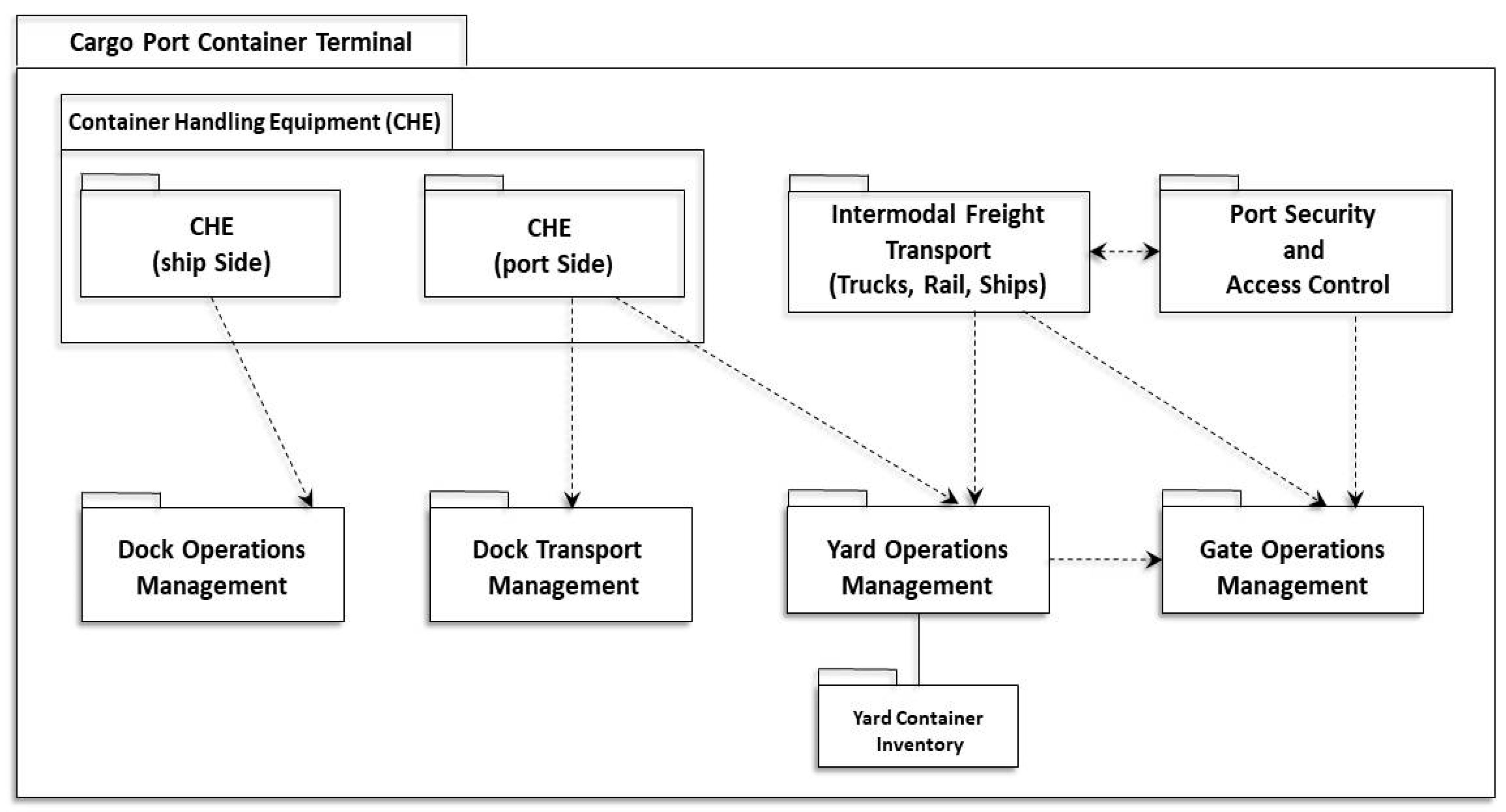
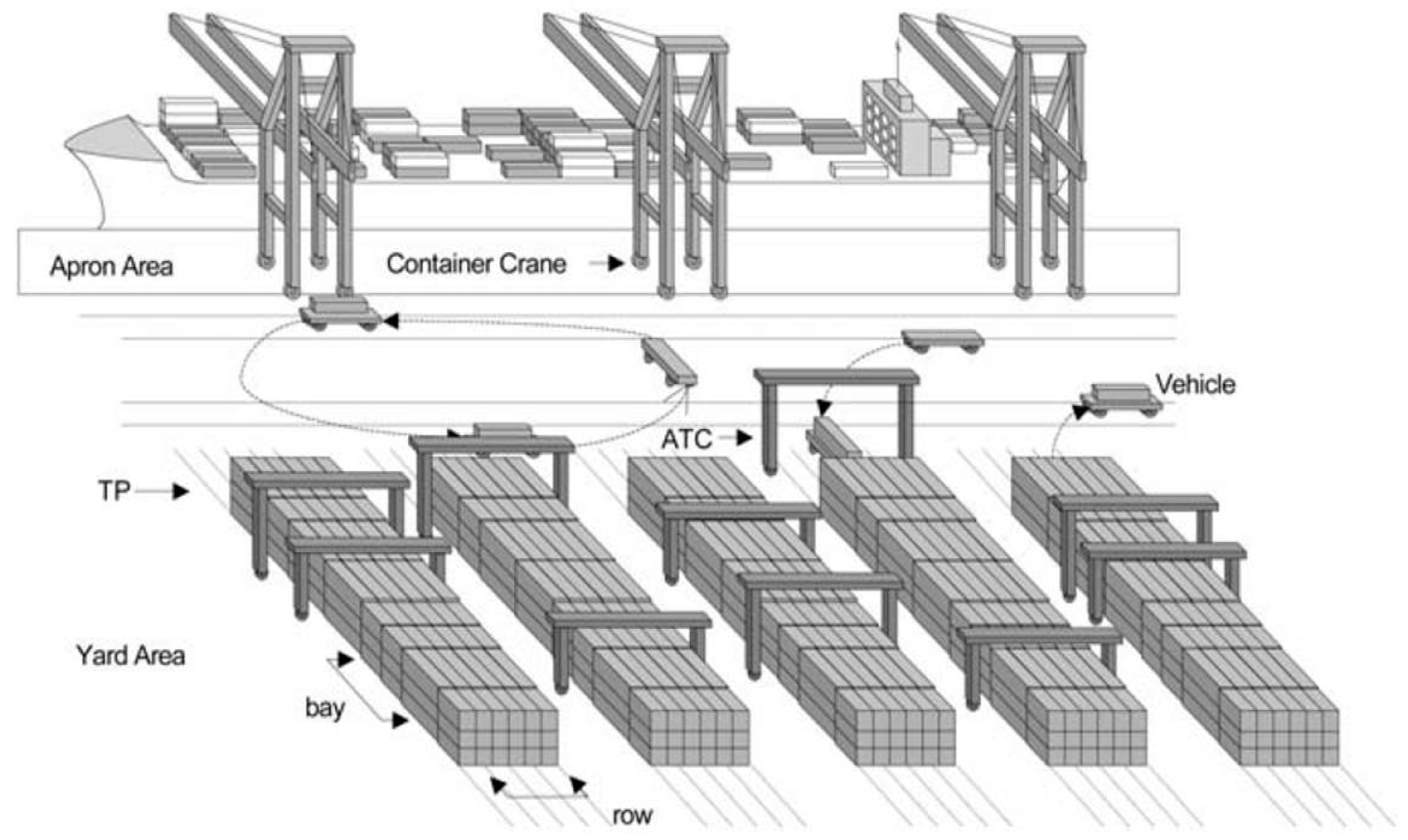
2.2.2. Container Terminal Overview
- An area for port physical security and access control; this incorporates the physical entrance to the terminal, video surveillance, gates, and the infrastructure necessary to check the credentials of the maritime transportation workers requiring unescorted access to the secure areas of the port. Credentials are typically biometric identification cards, also known as TWICs (Transport Worker Identification Cards);
- The cargo handling equipment at shipside and landside, which includes the container terminal cranes, transport vehicles, and similar conveyances;
- An area for intermodal transportation of the containers, such as commercial long-haul trucks, railways, or even other ships;
- A terminal operating center, incorporates the financial, communications, customs, IT security, and other back office functions.
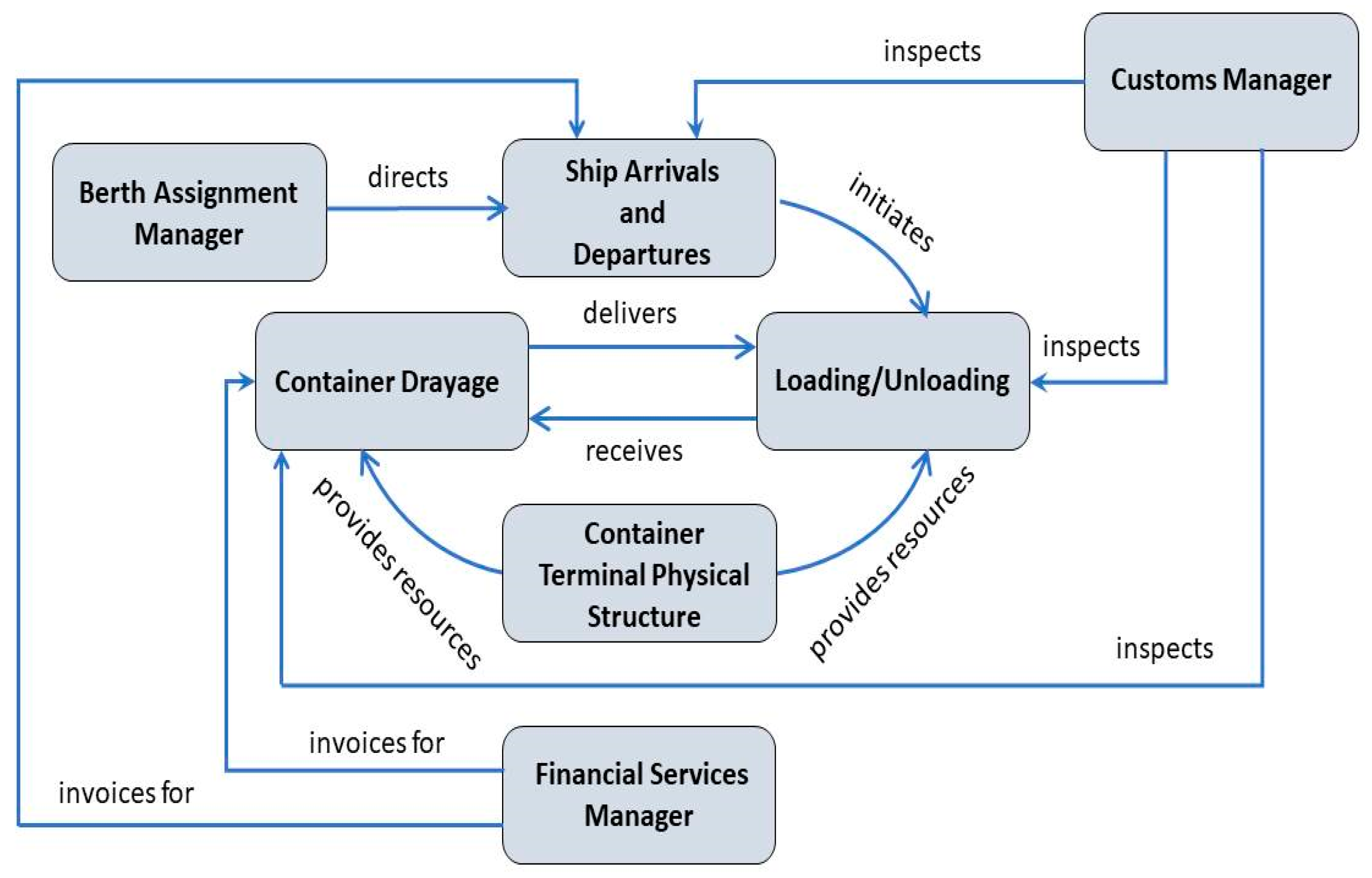
2.2.3. Container Terminal Operations
3. Building a Reference Architecture (RA) for a Cargo Port
3.1. Process Patterns
3.2. Use Case Model
3.3. Stakeholders
- Port Authority: responsible for the overall administration of the property, terminals, and other facilities on the port complex.
- Port Operations Manager: responsible for the efficient use of port facilities and resources with specific responsibilities for health, safety, and security. The individual works closely with regulatory authorities, port operations, and personnel of shipping lines. Manages resource allocation within the terminals and monitors expenditures.
- Terminal Operator (leasing company): legal entities that lease from port authorities their terminal facilities. Either the port authority or the terminal operator will supply the cranes and other cargo-handling equipment. It depends on the lease agreement between the port authority and each terminal operator.
- Terminal Operations Manager: responsible for the planning and administration of the operations at a port terminal in order to optimize resource use, minimize costs, and maintain quality standards. Activities associated with the transportation of cargo include the operation of vessels, cargo handling equipment, locomotives, trucks, vehicles, and storage and warehousing facilities related to the transportation of cargo. Assigned by the terminal leasing company.
- Gate Operations Manager: manage all gate, inter-, and intra-terminal transfer activities. Liaison with customers, port authorities, road container haulers, and truck drivers regarding terminal gate container transactions and transfer activities. Assigned by the terminal leasing company.
- Drayage Company: legal entities in charge of intermodal transportation, i.e., taking containers in and out of warehouses, rail terminals, ocean ports, and harbors. Assigned by shipping lines or terminal operators.
- Drayage Truck Driver Scheduler: an individual responsible for scheduling truck drivers for the drayage transaction (either drop or pick up a container). Assigned by the drayage company.
- Drayage Truck Driver: an individual responsible for dropping off or picking up a container.
- Terminal Trailer Driver: an individual responsible for moving the container to/from the ship to the storage area inside the terminal.
- Crane Operator Scheduler: an individual responsible for assigning crane operators to load/unload containers to/from the ship. Depending on the contract that the terminal operator has with the port authority, the crane operator scheduler can be assigned by the terminal operations manager or the port operations manager.
- Crane Operator: an individual that controls the operation of the STS crane when loading and unloading containers to/from a ship from either the crane’s cabin or a remote control room.
- Operations Officer: a member of a marine operations team involved in the safe transit and handling of vessels into and out of the port. The individual may also be involved in the berthing of vessels, port control and marine services, operation of harbors and marinas, conservancy, and environmental protection.
- Security Officer: an individual responsible for the protection of people, properties, and information at the port.
- Gate Control Employee: a member of the port authority organization.
- Harbor Master: an individual or system establishing a berthing schedule consisting of berthing times and berthing positions of containerships in port container terminals. The berth schedule must be constructed in a way to satisfy requests from carriers on berthing times and minimize handling efforts during ship operation.
- Marine Pilot: an individual employed by a port or harbor to ensure the safe navigation of ships in their waters. Pilots board ships entering or exiting the port and navigate them safely, avoiding hazards. Pilots may be faced with high-risk cargo, poor maneuverability, and communication difficulties.
- Tugboat Pilot: the pilot of a small vessel that helps larger crafts steer in tight spaces where their engines cannot safely reach full power.
3.4. Use Cases (UCs)
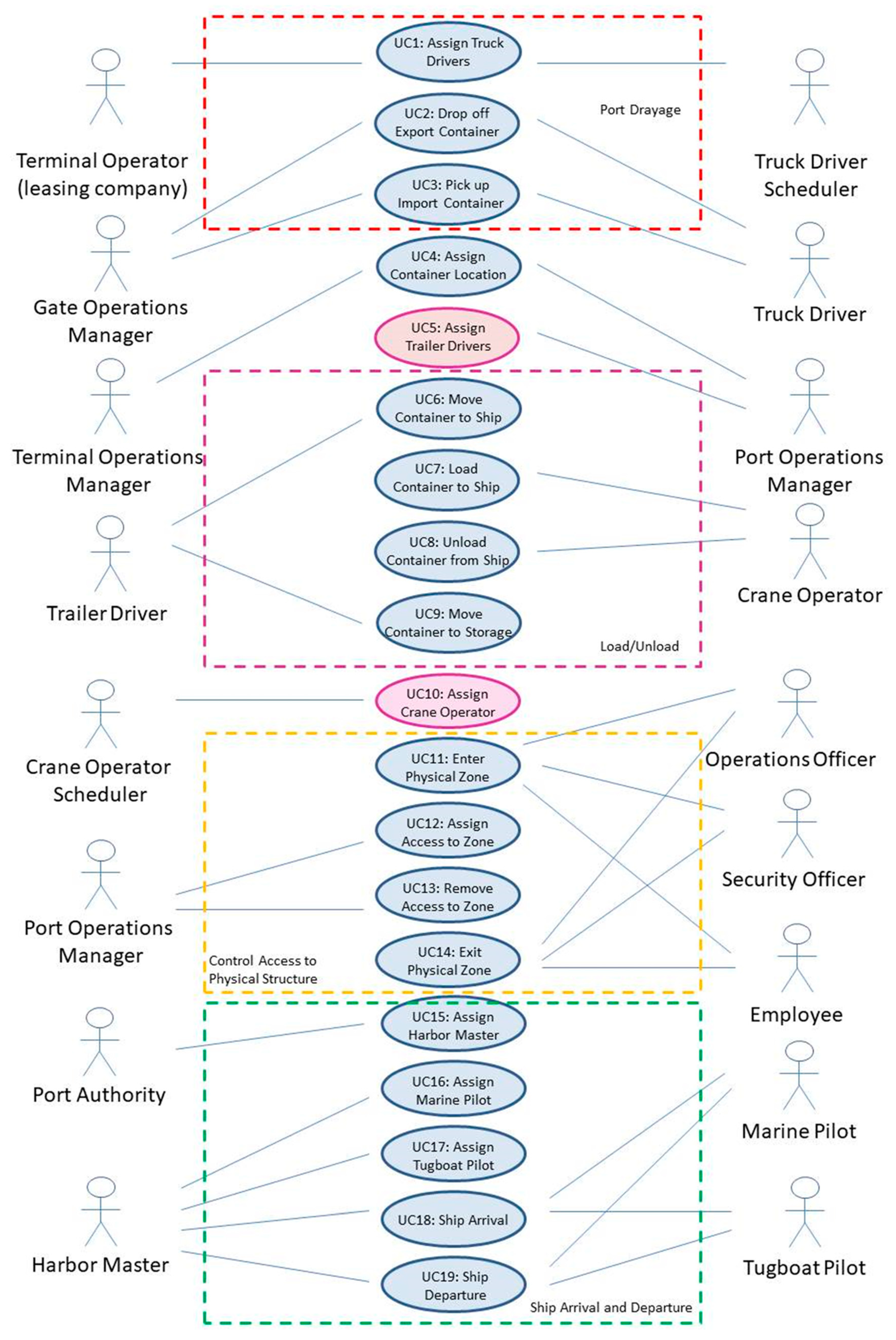
- UC1—Assign Drayage Truck Drivers: Actions taken by the drayage company truck driver scheduler to assign truck drivers to drop off or pick up containers from the cargo port. The drayage company may be assigned by the terminal operator (leasing company) or the shipping line. Actors: terminal operator (leasing company), drayage company truck driver, scheduler.
- UC2—Drop off Export Container: Actions taken by the drayage truck driver and the gate operations manager to allow entrance to the port and drop off an export container.Actors: gate operations manager, drayage truck driver.
- UC3—Pickup Import Container: Actions taken by the drayage truck driver and the gate operations manager to allow entrance to the port and pick up an import container. Actors: gate operations manager, drayage truck driver.
- UC4—Assign Container Location: Actions taken by the terminal operations manager or port operations manager controlling the logistics of the container terminal to assign container locations. Actors: terminal operations manager; port operations manager.
- UC5—Assign Trailer Drivers: Actions taken by the port operations manager to assign trailer/shuttle drivers to take the containers from the STS cranes to the drop-off point in the storage yard. Actors: port operations manager.
- UC6—Move Container to Ship: Actions taken by the trailer/shuttle driver to take the container from the storage yard to the ship. Actors: trailer driver.
- UC7—Load Container to Ship: Actions taken by crane operators to load outbound containers onto ships utilizing STS cranes. Actors: crane operator.
- UC8—Unload Container from Ship: Actions taken by crane operators to offload inbound containers from ships utilizing STS cranes. Actors: crane operator.
- UC9—Move Container to Storage: Actions taken by the trailer/shuttle driver to take the container from the ship to the storage yard. Actors: trailer driver.
- UC10—Assign Crane Operator: Actions taken by the crane operator scheduler to assign a crane operator to a specific STS crane. One crane operator may be assigned more than one STS crane. Actors: crane operator scheduler.
- UC11—Enter Physical Zone: Actions taken by an operations officer, a security officer, or an employee to have access to a specific area in the cargo port. Actors: operations officer, security officer, employee.
- UC12—Assign Access to Zone: Actions taken by the port operations manager to allow access by an individual to a specific zone. Actors: port operations manager.
- UC13—Remove Access to Zone: Actions taken by the port operations manager to remove access for an individual to a specific zone. Actors: port operations manager.
- UC14—Exit Physical Zone: Actions taken by an operations officer, a security officer, or an employee to exit a specific area in the cargo port. Actors: operations officer, security officer, employee.
- UC15—Assign Harbor Master: Actions taken by port operations to assign a harbor master to schedule vessel arrivals, departures, and berthing assignments. Actors: port authority.
- UC16—Assign Marine Pilot: Actions taken by the harbor master to assign a marine pilot to direct the ship to the port area. Actors: harbor master.
- UC17—Assign Tugboat Pilot: Actions taken by the harbor master to assign a tugboat pilot in case the ship requires the assistance of a tugboat for performing maneuvers in the port area and completing entrance and mooring operations. Actors: harbor master.
- UC18—Ship Arrival: Actions taken by the harbor master, marine pilot, and tugboat pilot to bring the ship to port. Actors: harbor master, marine pilot, tugboat pilot.
- UC19—Ship Departure: Actions taken by the harbor master, marine pilot, and tugboat pilot when the ship is departing the port. Actors: harbor master, marine pilot, tugboat pilot.
4. Patterns in a Cargo Port
4.1. Cargo Port Drayage
4.1.1. Intent
4.1.2. Context
4.1.3. Problem
- Flexibility: several internal and external roles may be involved, i.e., truck operators, storage area workers and supervisors, crane operators, etc. Resources and devices used, as well as their corresponding operations, must be flexible to accommodate this variety of roles [47];
- Usability: the software used to identify the individuals entering the port, their trucks, and their container contents should be easy to use by roles that do not have technical backgrounds;
- Alerting: any attempt to deviate from the normal operations of the terminal must produce an alert and should be logged;
- Logging: any activity should be recorded and logged for future auditing. In general, every visit should be logged to keep track of any access to the facility. All containers must be registered and logged;
- Location tracking—we need to be able to find every container. A container in the wrong place can delay operations.
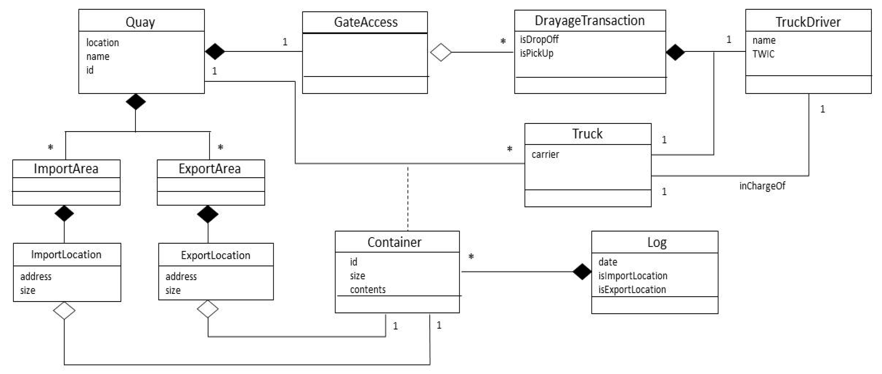
4.1.4. Solution
4.1.5. Structure
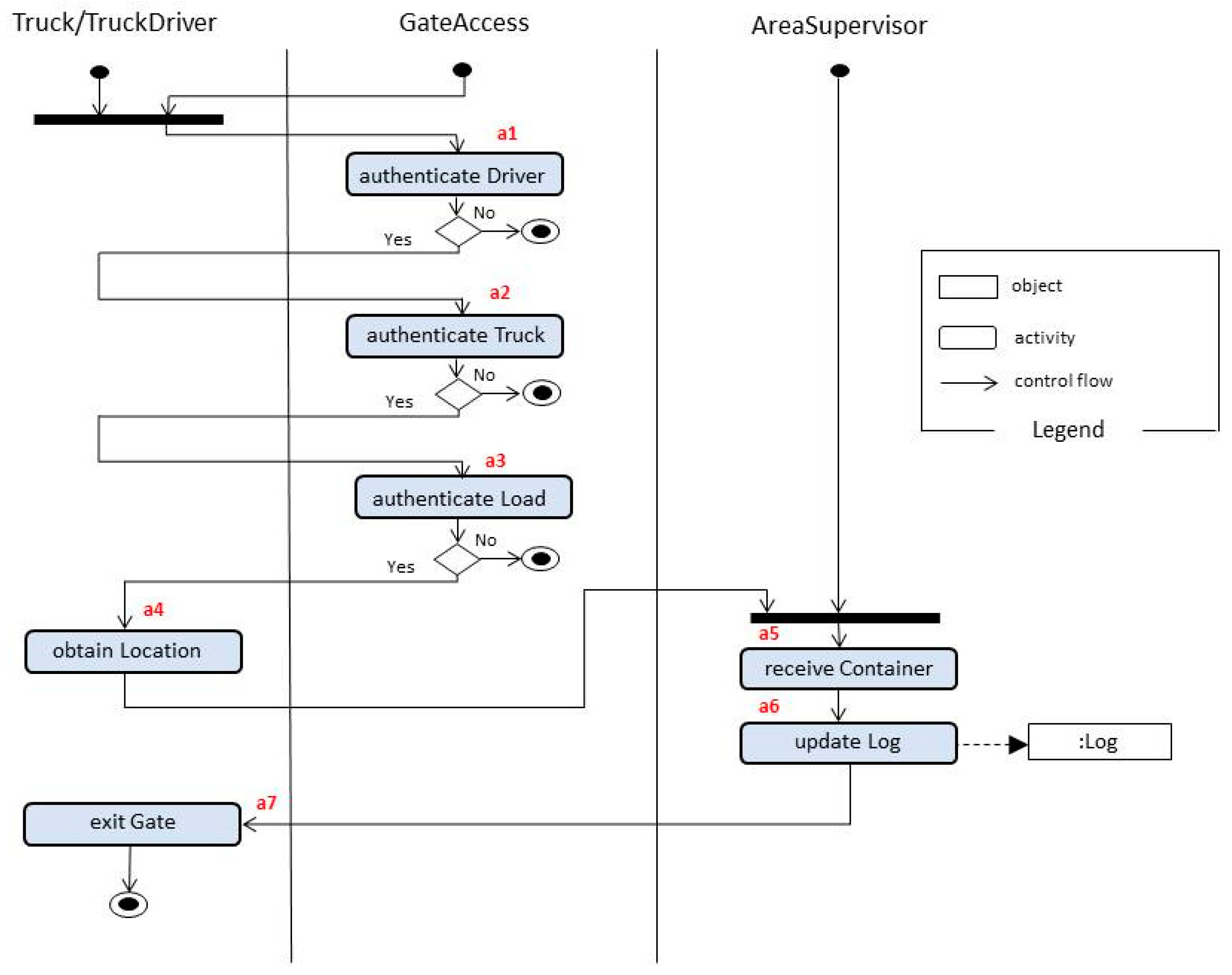
4.1.6. Dynamics
- TruckDriver arrives at the terminal entrance.
- GateAccess authenticates the driver.
- GateAccess authenticates the truck.
- GateAccess authenticates the container load.
- TruckDriver obtains the location for the drop and proceeds to the storage yard.
- TruckDriver drops the container in the appropriate location in the storage yard, exits the terminal, or picks up another container. The log is written, indicating the container ID and its location.
4.1.7. Implementation
4.1.8. Known Uses
4.1.9. Consequences
- Flexibility: role-based access control (RBAC) [50] allows us to accommodate several roles that participate in the system; it allows for all types of users. People performing the same tasks are given the same rights;
- Usability: easy to use by individuals that do not have technical backgrounds;
- Alerting: we can use the alarm monitoring, security logger, and auditor patterns to record all activities that are security relevant. Any deviation from normal activities will be logged, and if necessary, an alert will be displayed;
- Logging: the places where the containers have been placed are registered. All transactions are logged and later audited to assure compliance with security regulations;
- Location Tracking: logging will keep track of locating the containers.
- All the mechanisms needed for the process require extra personnel and maintenance, and they have an associated extra cost. Containers may have dangerous loads, and physical measures are needed to detect them, such as X-rays and radiation portal monitors that may be costly.
4.2. Cargo Port Loading and Unloading
4.2.1. Intent
4.2.2. Context
4.2.3. Problem
- Flexibility: a variety of users are involved in ports. They are required to operate the facility and have assigned roles. Some external users can also have access for administrative or management purposes. We need to accommodate this variety of roles;
- Safety: the equipment has physical limits that cannot be exceeded because they would get damaged or endanger the port workers;
- Records: we need to record all activities that may need to be audited later to record any type of violation.
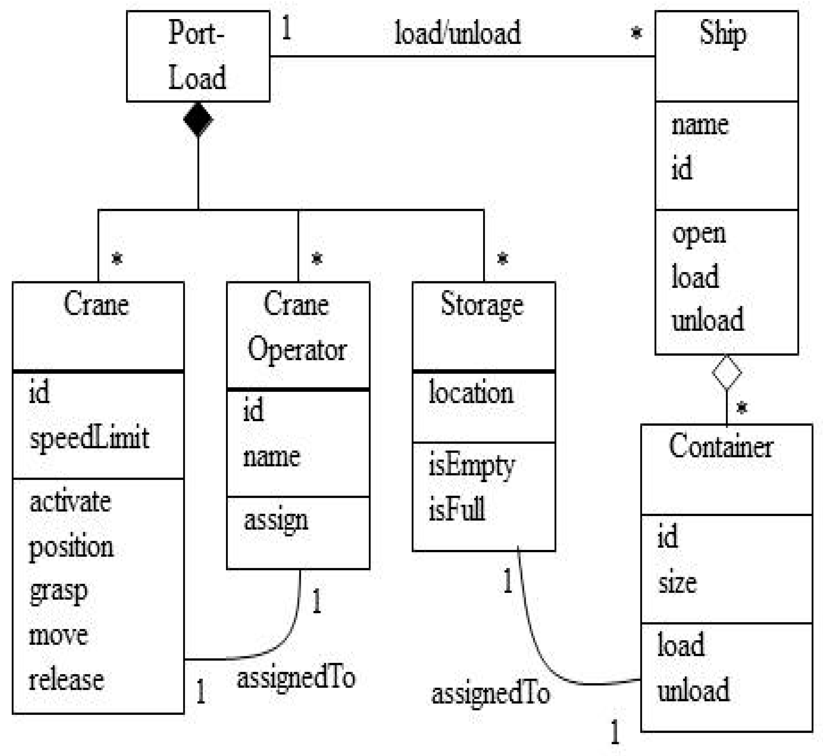
4.2.4. Solution
4.2.5. Structure
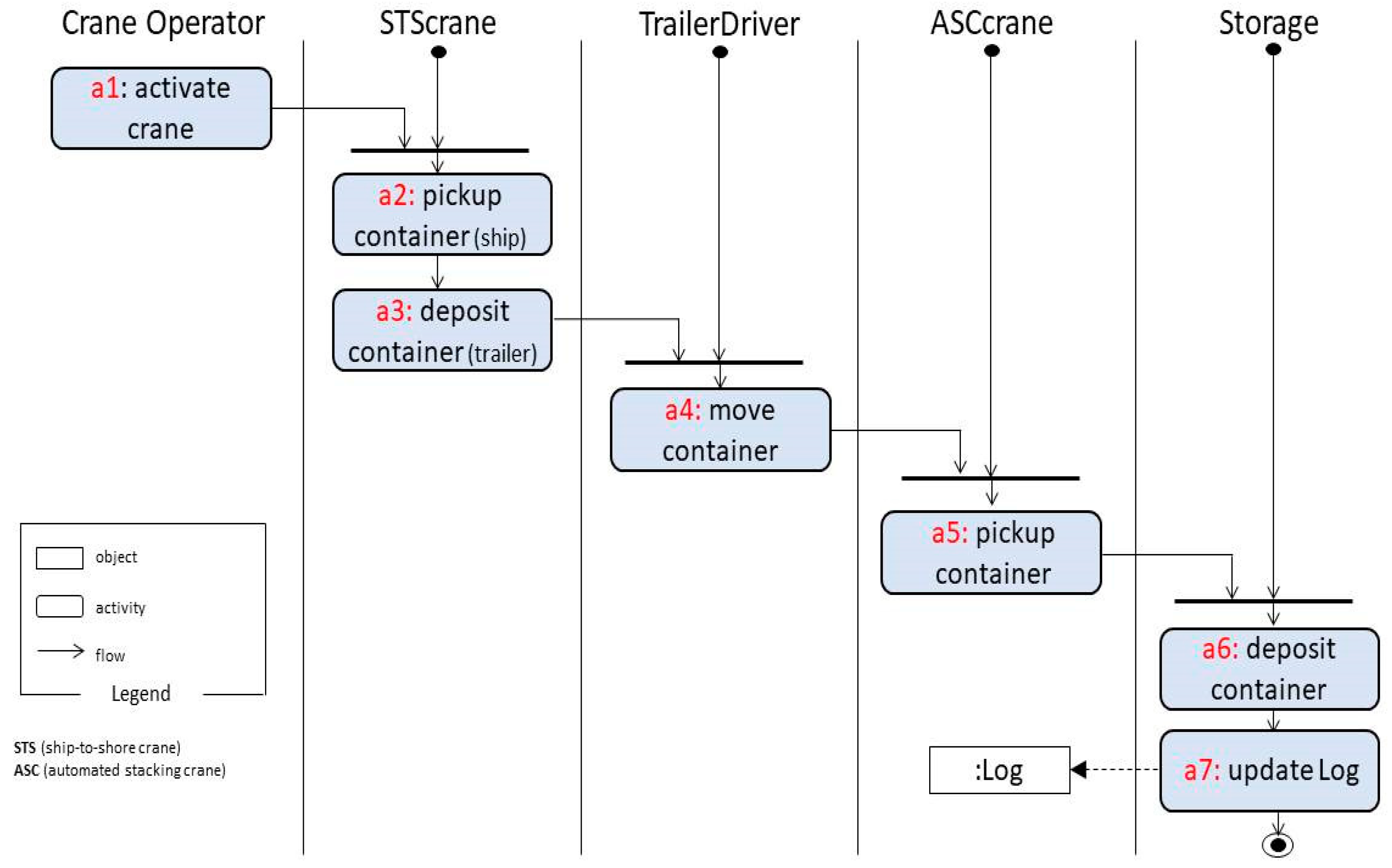
4.2.6. Dynamics
- Crane operator activates the crane.
- Crane operator picks up container from the ship.
- Crane operator deposits the container in the trailer.
- Trailer driver receives the container.
- Trailer driver takes the container to the stacking crane transfer point.
- ASC picks up the container and finds its location in storage.
- ASC deposits container in an appropriate place in storage.
- Transaction is logged.
4.2.7. Implementation
4.2.8. Known Uses
4.2.9. Consequences
- Flexibility: RBAC allows for accommodating any kinds of roles appropriate for all kinds of users;
- Safety: The equipment’s physical limits can be controlled with safety assertions. Other assertions can prevent situations that would be dangerous for humans;
- Records: We can use the security logger/auditor pattern to record security-relevant activities.
- There is the possibility that containers have dangerous loads, and we need physical measures to detect them.
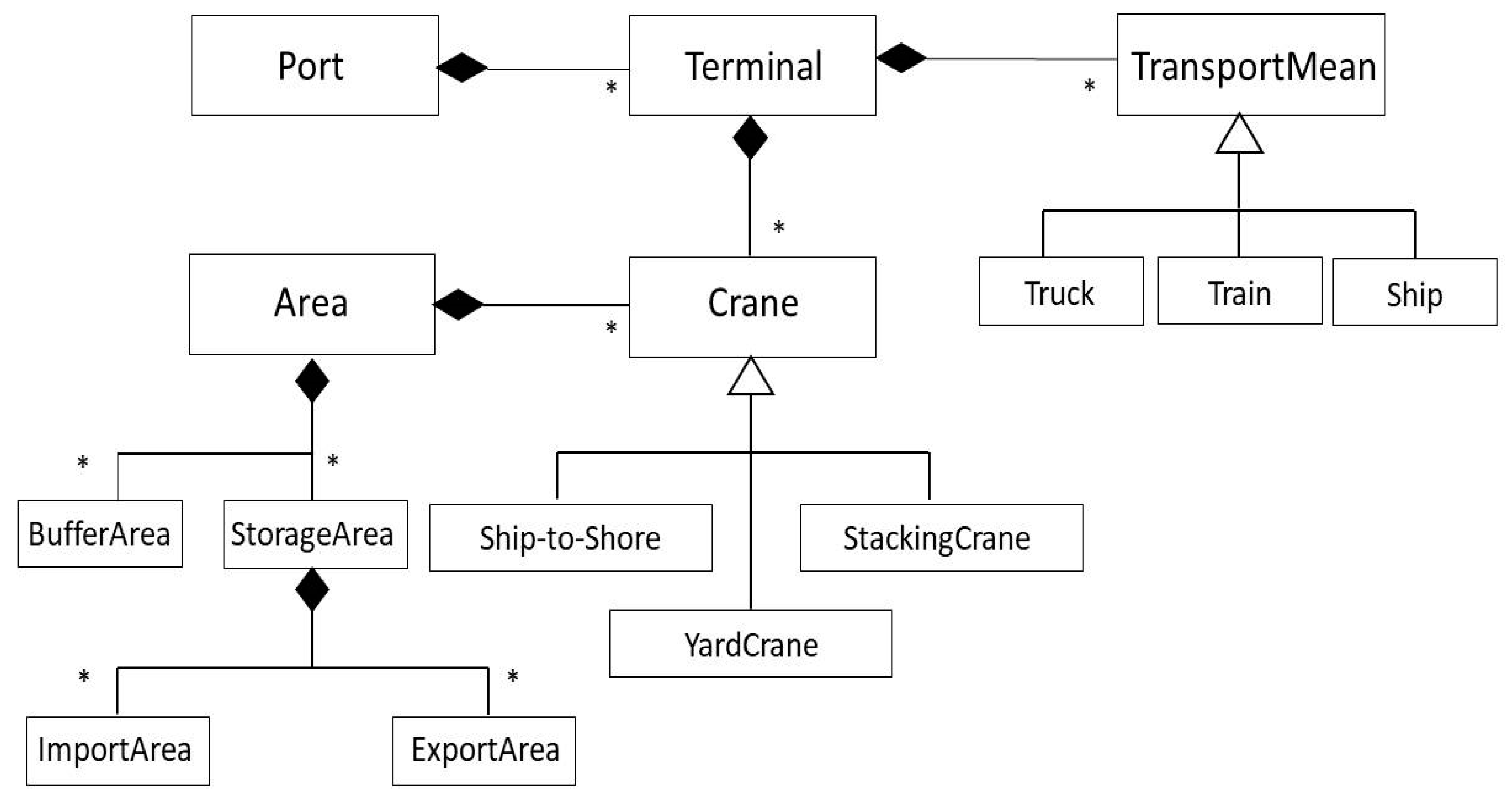
4.3. Container Terminal Physical Structure
4.3.1. Intent
4.3.2. Context
4.3.3. Problem
- Flexibility: the description of the physical structure should be flexible and scalable. The physical units may change their functions, within restrictions, and we may need more physical units of some type;
- Scalability: the number of buildings and their divisions can change up or down depending on the amount of work required;
- Upgradability: should allow for changes in the structure to add or remove port functions;
- Physical Security: need to provide a good level of security for cargo port functions.
4.3.4. Solution
4.3.5. Structure
4.3.6. Implementation
4.3.7. Known Uses
4.3.8. Consequences
- Flexibility: this pattern is flexible enough that we can add other types of cranes and other types of areas to store the containers, i.e., areas to handle refrigerated containers, areas to store liquids, etc;
- Scalability: this pattern provides for any amount of container handling equipment, vehicles used to move the containers around the terminal, and storage areas, depending on the amount of work required;
- Upgradability: this pattern allows for any changes in functionality, such as adding or removing port functions;
- This pattern does not detect dangerous loads, and physical measures are needed to detect them, such as X-rays and radiation portal monitors that may be costly.
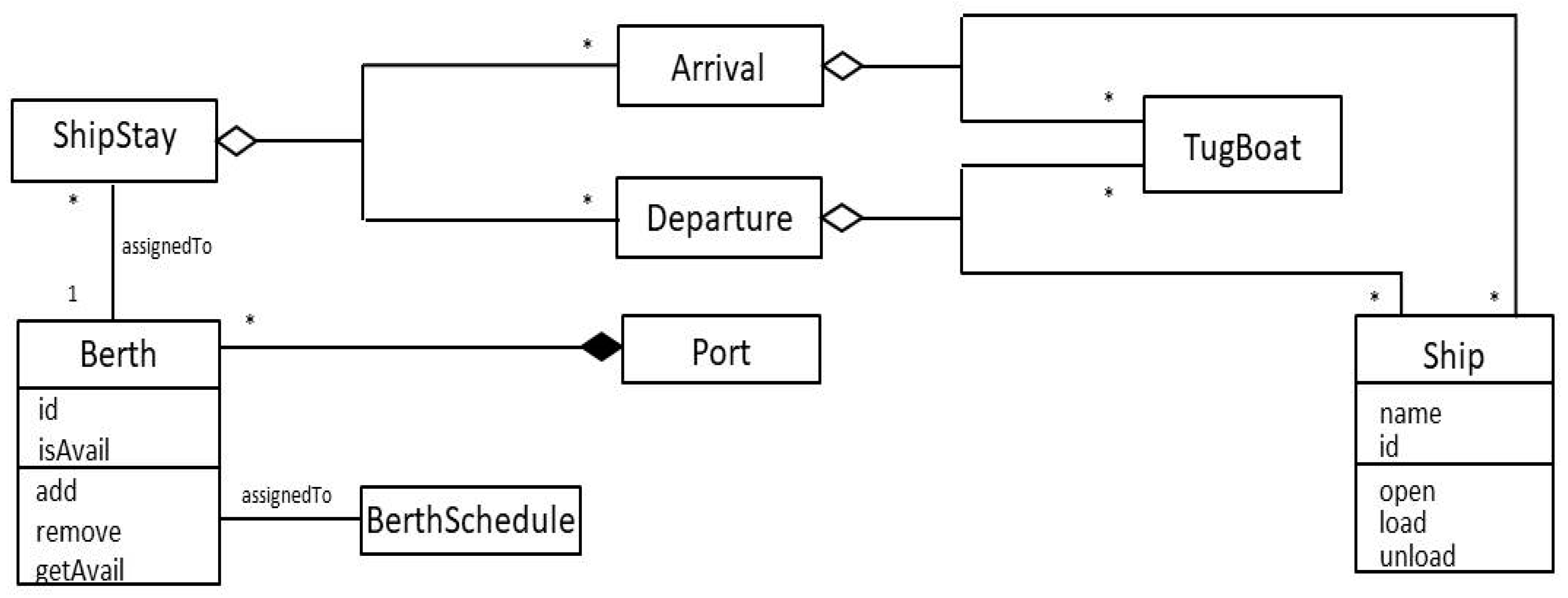
4.4. Ship Arrivals and Departures
4.4.1. Intent
4.4.2. Context
4.4.3. Problem
- Availability: berth facilities must be assigned in advance and in such a way as to minimize ship stays in the port;
- Scalability: the number of provisioned, designated locations to dock in a port should vary depending on the traffic of vessels to the port. New berths can be provisioned for loading/unloading as needed;
- Berth Scheduling: berth scheduling should be based on the priority of resource allocation and a comparison of the vessel and berth data. How to assign its berth time and position is of great importance to improving the level of port services and reducing the port’s cost of production;
- Safety and Port Integrity: arrival and departure procedures should ensure the safety of the ship’s arrival and departure, both for the people on board as well as those at the seaport. Most of the collisions and groundings of ships are reported during the maneuvering of the vessels in port, and hence the maneuvering operation at port arrival or departure is considered the most crucial time a ship faces in her voyage. The availability of marine pilots and tugboats should ensure the avoidance of physical damage [54].
4.4.4. Solution
4.4.5. Structure
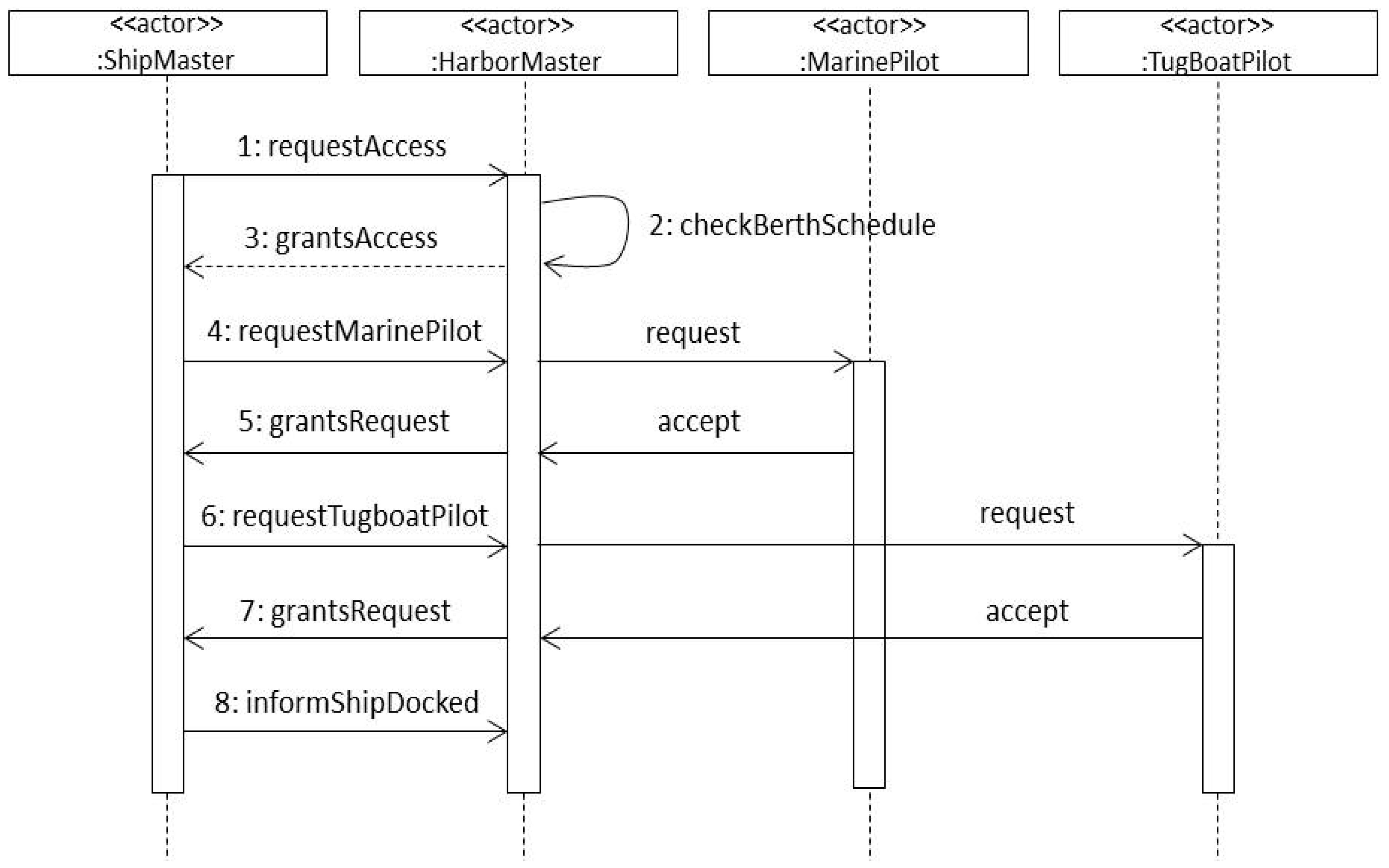
4.4.6. Dynamics
- Ship master contacts harbor master and requests access to the port.
- Harbor master checks the berthing schedule.
- Harbor master grants access for ships to berth.
- Ship master requests a marine pilot to bring the ship to port.
- Harbor master grants request to send marine pilot.
- Ship master requests a tugboat for maneuvering vessel in port.
- Harbor master grants request to send tugboat pilot and tugboat to assist ship.
- Ship master informs ship docked in berth.
4.4.7. Implementation
4.4.8. Known Uses
4.4.9. Consequences
- Availability: port facilities work 24 h a day. By previously scheduling with the harbor master, vessels can arrive at a port at any time. Ports are always open and available to vessels when needed;
- Scalability: ports and harbor masters provision berths for vessels to dock depending on traffic and the number of vessels entering the port;
- Berth scheduling: proper berth assignment and scheduling ensure that the vessel characteristics are compatible with the characteristics of the berth to which the vessel is scheduled. It improves the level of port services and reduces the port’s cost of production;
- Safety and port Integrity: arrival and departure procedures ensure that the essential safety steps are followed both for the people on board as well as those at the seaport. Most of the collisions and consequent grounding of ships are avoided by utilizing experienced marine pilots and tugboat pilots to aid in the mooring of a vessel.
- Having experienced marine pilots and tugboats reserved and waiting to help the ships dock increases the cost of running the port.
5. A Reference Architecture for a Cargo Port
6. Validation of the RA
7. Value and Use of the Reference Architecture in Cargo Port Design and Operation
- RAs aggregate knowledge and design expertise in a specific domain [23]. This knowledge can be reused to build new ports and improve existing ones.
- Holistic and unified models such as RAs are useful for gaining understanding of a complex system and its limitations. Cargo ports are very complex systems, and having an abstract architecture free of implementation details is very important to understanding the system.
- An RA serves as a way to decompose a complex system into simpler and more coherent parts that can be assigned to different types of specialists.
- Automation is now a basic objective to increase efficiency and reduce costs, and an RA can provide a perspective on how the automation of parts of the system contributes to the efficiency of port operation.
- UML models used to represent the RA provide more precision as compared to other descriptions such as block diagrams.
- We can contribute to the standardization of concrete architectures by using the RA as a template. Standardization can accelerate automation and reduce costs [63].
- An RA serves as a way to unify terminology and make it easier to train the developers, system architects, and administrators so they become familiar with the platforms and processes.
- Abstract representational models of the cargo port components in the RA help address heterogeneity; this is accomplished by focusing on the general categories of the system and grouping them on the basis of similarities in structure and functionality.
- We can identify common functionalities and configurations to encourage reuse in new projects.
- RAs support interoperability among different applications and their components by establishing common mechanisms for information exchange.
- RAs can serve as a guideline to indicate where to add defenses for the expected threats and for adding security monitoring in the physical port.
- Security, compliance, privacy, safety, reliability, and governance can all be improved by the use of these models. For example, the analysis of threats in complex systems can be done systematically with the help of RAs [17].
8. Related Work
8.1. Papers That Use Patterns and/or UML Models to Describe CPS Architectures
8.2. Architectures of Transportation Systems
8.3. Architectures Proposed as Part of Descriptions of CPSs or Development Methodologies
8.4. Architectures for Other Types of CPSs
8.5. Papers about Quality Aspects of CPSs
8.6. Papers about Development Methodologies for CPSs
9. Conclusions and Future Work
Author Contributions
Funding
Informed Consent Statement
Data Availability Statement
Acknowledgments
Conflicts of Interest
References
- Lee, E.A. Cyber Physical Systems: Design Challenges. In Proceedings of the 11th IEEE International Symposium on Object and Component-Oriented Real-Time Distributed Computing, Orlando, FL, USA, 5–7 May 2008; pp. 363–369. [Google Scholar]
- Denker, G.; Dutt, N.; Mehrotra, S.; Stehr, M.-O.; Talcott, C.; Venkatasubramanian, N. Resilient dependable cyber-physical systems: A middleware perspective. J. Internet Serv. Appl. 2012, 3, 41–49. [Google Scholar] [CrossRef]
- Yimam, D.; Fernandez, E.B. Building Compliance and Security Reference Architectures for cloud systems. In Proceedings of the IEEE International Conference on Cloud Engineering (IC2E) 2016, Berlin, Germany, 4–8 April 2016. [Google Scholar]
- Gottschalk, M.; Delfs, C.; Model, T.S.G.A. The Use Case and Smart Grid Architecture Model Approach; Springer: Berlin, Germany, 2017; pp. 41–61. [Google Scholar]
- Avgeriou, P. Describing, Instantiating and Evaluating a Reference Architecture: A Case Study. Enterp. Archit. J. 2003, 342, 1–24. [Google Scholar]
- Taylor, R.N.; Medvidovic, N.; Dashofy, E.M. Software Architecture: Foundations, Theory, and Practice; Wiley: London, UK, 2009; ISBN 0470167742, 9780470167748. [Google Scholar]
- Buschmann, F.; Meunier, R.; Rohnert, H.; Sommerlad, P.; Stal, M.; Architecture, P.-O.S. A System of Patterns; John Wiley Sons Ltd.: New York, NY, USA, 1996; Volume 1. [Google Scholar]
- Gamma, E.; Helm, R.; Johnson, R.; Vlissides, J. Design Patterns: Elements of Reusable Object-Oriented Software; Addison-Wesley: Boston, CM, USA, 1994. [Google Scholar]
- Romero, V.M.; Fernandez, E.B. Towards a Security Reference Architecture for Cyber Physical Systems. In Proceedings of the Fifthteen Latin American and Caribbean Conference for Engineering and Technology, Boca Raton, FL, USA, 19–21 July 2017. [Google Scholar]
- Warmer, J.; Kleppe, A. The Object Constraint Language: Getting Your Models Ready for MDA, 2nd ed.; Addison-Wesley Longman: Boston, MA, USA, 2013; ISBN 0321179366. [Google Scholar]
- Garavel, H.; Graf, S. Formal methods for safe and secure computer systems. In Technical Report. BSI Study 875; Federal Office for Information Security: Bonn, Germany, 2013. [Google Scholar]
- Pereira-Vale, A.; Fernandez, E.B. An Ontology for Security Patterns. In Proceedings of the 38th International Conference of the Chilean Computer Science Society (SCCC 2019), Concepción, Chile, 4–8 November 2019. [Google Scholar]
- Weyrich, M.; Ebert, C. Reference architectures for the internet of things. IEEE Softw. 2015, 33, 112–116. [Google Scholar] [CrossRef]
- Seiger, R. Modelling complex and flexible processes for smart cyber-physical environments. J. Comput. Sci. 2015, 10, 137–148. [Google Scholar] [CrossRef]
- Romero, V.M.; Fernandez, E.B. A Pattern for Secure Cargo Port Drayage. In Proceedings of the 7th Asian Conference on Pattern Languages of Programs, Asian PLoP’18, Tokyo, Japan, 1–2 March 2018; p. 9. [Google Scholar]
- Fernandez, E.B.; Monge, R.; Carvajal, R. A pattern for a secure and safe port loading facility. In Proceedings of the 10th Latin American Conference on Pattern Languages of Programs—SugarLoafPLoP, Rio de Janeiro, Brazil, 20–23 November 2014. [Google Scholar]
- Fernandez, E.B.; Romero, V. A security reference architecture for cargo ports. Internet Things Cyber-Phys. Syst. 2022, 2, 120–137. [Google Scholar] [CrossRef]
- Buschmann, F.; Henney, K.; Schmidt, D.C. Architecture, Pattern-Oriented Software Architecture: On Patterns and Pattern Languages; John Wiley Sons Ltd.: Hoboken, NJ, USA, 2007; Volume 5. [Google Scholar]
- Wieringa, R. Design Science as nested problem solving. In Proceedings of the 4th International Conference on Design Science Research in Information Systems and Technology, New York, NY, USA, 7–8 May 2009. [Google Scholar]
- Fernandez, E.B. Security Patterns in Practice: Building Secure Architectures Using Software Patterns; Wiley Series on Software Design Patterns: Chichester, UK, 2013. [Google Scholar]
- Fernandez, E.B.; Pelaez, J.; Larrondo-Petrie, M. Attack Patterns: A New Forensic and Design Tool. In Advances in Digital Forensics III; Springer: New York, NY, USA, 2007; pp. 345–357. [Google Scholar]
- Fernandez, E.B.; Yoshioka, N.; Washizaki, H. Modeling Misuse Patterns. In Proceedings of the 2009 International Conference on Availability, Reliability, and Security (ARES 2009), Fukuoka, Japan, 16–19 March 2009; pp. 566–571. [Google Scholar]
- Bucaioni, A. Reference architectures modelling and compliance checking. Softw. Syst. Model. 2022, 1–27. [Google Scholar] [CrossRef]
- Stricker, V.; Lauenroth, K.; Corte, P.; Gittler, F.; Panfilis, S.D.; Pohl, K. Creating a reference architecture for service-based systems—A pattern-based approach. In Towards the Future Internet—Emerging Trends from European Research; IOS Press: Amsterdam, The Netherlands, 2010; pp. 149–160. [Google Scholar] [CrossRef]
- Uslar, M.; Rohjans, S.; Neureiter, C.; Andrén, F.P.; Velasquez, J.; Steinbrink, C.; Efthymiou, V.; Migliavacca, G.; Horsmanheimo, S.; Brunner, H.; et al. Applying the Smart Grid Architecture Model for Designing and Validating System-of-Systems in the Power and Energy Domain: A European Perspective. Energies 2019, 12, 258. [Google Scholar] [CrossRef]
- Fernandez, E.B.; Monge, R.; Hashizume, K. Building a security reference architecture for cloud systems. Requir. Eng. 2016, 21, 225–249. [Google Scholar] [CrossRef]
- Romero, V.M.; Fernandez, E.B. Building a Reference Architecture for Cargo Ports using Patterns. In Proceedings of the Sixteenth Latin American and Caribbean Conference for Engineering and Technology, Lima, Peru, 18–20 July 2018. [Google Scholar]
- US Dept. of Transportation, Research and Innovative Technology Administration. In Freight Transportation: Global Highlights; Bureau of Transportation Statistics: Washington, DC, USA, 2010.
- Available online: http://www.rita.dot.gov/bts/sites/rita.dot.gov.bts/files/publications/freight_transportation/pdf/entire.pdf (accessed on 14 February 2023).
- Bureau, P.R. 2011 World Population Data Sheet. (Washington, DC: 2012). Available online: http://www.prb.org/pdf11/2011population-data-sheet_eng.pdf (accessed on 1 May 2013).
- The World Bank, Container Port Traffic. Available online: https://data.worldbank.org/indicator/IS.SHP.GOOD.TU (accessed on 14 February 2023).
- US Dept. of Transportation, Research and Innovative Technology Administration, Bureau of Transportation Statistics. America’s Container Ports: Linking Markets at Home and Abroad; Washington, DC, USA. 2011. Available online: https://www.bts.gov/publications/americas_container_ports/2011/pdf/entire.pdf (accessed on 1 May 2013).
- Magazine, F. Internet Reference. Available online: http://fortune.com/2018/01/30/port-automation-robots-container-ships/ (accessed on 14 February 2023).
- Yang, C.H.; Choi, Y.S.; Ha, T.Y. Simulation-based performance evaluation of transport vehicles at automated container terminals. OR Spectr. 2004, 26, 149–170. [Google Scholar] [CrossRef]
- YorkWallischeck, E. ICS Security in Maritime Transportation A White Paper Examining the Security and Resiliency of Critical Transportation Infrastructure; DOT-VNTSC-MARAD-13-01; Bureau of Transportation Statistics: Washington, DC, USA, 2013. [Google Scholar]
- Bielli, M.; Boulmakoul, A.; Rida, M. Object Oriented Model for Container Terminal Distributed Simulation. Eur. J. Oper. Res. 2006, 175, 1731–1751. [Google Scholar] [CrossRef]
- Boulmakoul, A.; Rida, M. Discrete event simulation component specification for container terminals operational management. In Proceedings of the 2nd IEEE ISSPIT (International Symposium on Signal Processing and Information Technology), Marrakesh, Morocco, 18–21 December 2002; pp. 266–271. [Google Scholar]
- Organization, P. Internet Reference. Available online: https://www.pema.org/wp-content/uploads/downloads/2016/06/PEMA-IP12-Container-Terminal-Automation.pdf (accessed on 14 February 2023).
- Steenken, D.; Voß, S.; Stahlbock, R. Container terminal operation and operations research-a classification and literature review. OR Spectr. 2004, 26, 3. [Google Scholar] [CrossRef]
- Cheng, Y.L.; Sen, H.C.; Natarajan, K.; Teo, C.P.; Tan, K.C. Dispatching Automated Guided Vehicles in a Container Terminal. In Supply Chain Optimization. Applied Optimizatio; Geunes, J., Pardalos, P.M., Eds.; Springer: Boston, MA, USA, 2005; Volume 98. [Google Scholar]
- Zaffalon, M.; Rizzoli, A.E.; Gambardella, L.M.; Mastrolilli, M. Resource allocation and scheduling of operations in an intermodal terminal. In Proceedings of the 10th European Simulation Symposium and Exhibition, Simulation in Industry, ESS98, Nottingham, UK, 26–28 October 1998; pp. 520–528. [Google Scholar]
- Günther, H.; Kim, K.H. Container Terminals and Automated Transport Systems: Logistics Control Issues and Quantitative Decision Support; Springer Science & Business Media: Berlin/Heidelberg, Germany, 2005. [Google Scholar]
- Lethbridge, T.C.; Laganière, R. Object-Oriented Software Engineering: Practical Software Development Using UML and Java; McGraw-Hill: New York, NY, USA, 2001; Volume 102. [Google Scholar]
- Angelov, S.; Grefen, P.; Greefhorst, D. A framework for analysis and design of software reference architectures. Inf. Softw. Technol. 2012, 54, 417–431. [Google Scholar] [CrossRef]
- Pankowska, M. Stakeholder Oriented Enterprise Architecture Modelling. In Proceedings of the 12th International Conference on e-Business, Colmar, France, 20–22 July 2015. [Google Scholar]
- Notteboom, T.; Winkelmans, W. Stakeholder Relations Management in ports: Dealing with the interplay of forces among stakeholders in a changing competitive environment. In Proceedings of the IAME 2002 Maritime Economics: Setting the Foundations for Port and Shipping Policies, Panama City, Panama, 12–15 November 2002. [Google Scholar]
- Syed, M.H.; Fernandez, E.B. A reference architecture for the container ecosystem. In Proceedings of the 13th International Conference on Availability, Reliability and Security (ARES 2018), Hamburg, Germany, 27–30 August 2018; ACM: New York, NY, USA, 2018. [Google Scholar]
- Saini, K.; Kaur, S. Forensic Examination of Computer-Manipulated Documents using Image Processing Techniques. Egypt. J. Forensic Sci. 2016, 6, 317–322. [Google Scholar] [CrossRef]
- National Cooperative Freight Research Program, N.C.R.P. Report 11. Truck Drayage Productivity Guide; Grant No. DTOS59-06-00039; The National Academies Press: Washington, DC, USA, 2011. [Google Scholar]
- The Port of Los Angeles Port Drayage. Available online: https://www.portoflosangeles.org/ (accessed on 14 February 2023).
- The Port of Long Beach Port Drayage. Available online: https://www.polb.com/ (accessed on 14 February 2023).
- Stallings, W.; Brown, L. Computer Security: Principles and Practice, 4th ed.; Pearson: London, UK, 2018. [Google Scholar]
- Port Everglades Website, Broward County, FL, USA. Available online: https://www.porteverglades.net/articles/post/port-everglades-inspects-new-super-post-panamax-cranes/ (accessed on 14 February 2023).
- Fernandez, E.B.; Sorgente, T.; VanHilst, M. Constrained Resource Assignment Description Pattern. In Proceedings of the Nordic Conference on Pattern Languages of Programs, Viking PLoP 2005, Otaniemi, Finland, 23–25 September 2005. [Google Scholar]
- Longo, F.; Padovano, A.; Baveja, A.; Melamed, B. Challenges and opportunities in implementing green initiatives for port terminals. In Proceedings of the 3rd International Workshop on Simulation for Energy, Sustainable Development and Environment, SESDE 2015, Bergeggi, Italy, 21–23 September 2015. [Google Scholar]
- Marine Insight. Available online: https://www.marineinsight.com/guidelines/general-procedure-of-preparing-ships-for-entering-ports/ (accessed on 14 February 2023).
- Kaluza, P.; Kölzsch, A.; Gastner, M.T.; Blasius, B. The complex network of global cargo ship movements. J. R. Soc. Interface 2010, 7, 1093–1103. [Google Scholar] [CrossRef]
- Fernandez, E.B.; Ballesteros, J.; Desouza-Doucet, A.C.; Larrondo-Petrie, M.M. Security Patterns for Physical Access Control Systems. In Data and Applications Security XXI. DBSec 2007. Lecture Notes in Computer Science; Barker, S., Ahn, G.J., Eds.; Springer: Berlin/Heidelberg, Germany, 2007; Volume 4602. [Google Scholar]
- Martínez-Fernández, S.; Ayala, C.P.; Franch, X.; Marques, H.M. Benefits and drawbacks of software reference architectures: A case study. Inf. Softw. Technol. 2017, 88, 37–52. [Google Scholar] [CrossRef]
- Group, T.B. Container Port Design and Planning. Available online: https://tba.group/en/services/bulk-container-terminal-design (accessed on 14 February 2023).
- Wikipedia, Container Port Design Process. Available online: https://en.wikipedia.org/wiki/Container_port_design_process (accessed on 14 February 2023).
- Cisco, Ports and Terminals Design Guide. Available online: https://www.cisco.com/c/en/us/td/docs/solutions/Verticals/CCI/Ports/DG/cci-ports-dg/cci-ports-dg.html (accessed on 14 February 2023).
- Martin-Soberon, A.M.; Monfort, A.; Sapina, R.; Monterde, N.; Calduch, D. Automation in port container terminals. Procedia-Soc. Behav. Sci. 2014, 160, 195–204. [Google Scholar] [CrossRef]
- Maidl, M.; Wirtz, R.; Zhao, T.; Heisel, M.; Wagner, M. Pattern-based modeling of cyber-physical systems for analyzing security. In Proceedings of the 24th European Conference on Pattern Languages of Programs, Irsee, Germany, 3–7 July 2019; Volume 23, pp. 1–10. [Google Scholar]
- Hehenberger, P.; Achiche, S. Design, modelling, simulation and integration of cyber physical systems: Methods and applications. Comput. Ind. 2016, 82, 273–289. [Google Scholar] [CrossRef]
- Tan, Y.; Goddard, S.; Perez, L.C. A prototype architecture for cyber-physical systems. ACM Sigbed Rev. 2008, 5, 1–2. [Google Scholar] [CrossRef]
- Thurston, T.; Hu, H. Distributed agent architecture for port automation. In Proceedings of the 26th Annual International Computer Software and Applications, Oxford, England, 26–29 August 2002. [Google Scholar] [CrossRef]
- La, H.J.; Kim, S.D. A service-based approach to designing cyber-physical systems. In Proceedings of the 9th IEEE/ACIS International Conference on Computer and Information Science, Washington, DC, USA, 18–20 August 2010; pp. 895–900. [Google Scholar]
- Hashizume, K.; Fernandez, E.B.; Larrondo-Petrie, M. Cloud infrastructure pattern. First International Symposium on Software Architecture and Patterns; LACCEI: Panama City, Panama, 2012; pp. 23–27. [Google Scholar]
- Hashizume, K.; Fernandez, E.B.; Larrondo-Petrie, M.M. Cloud service model patterns. In Proceedings of the 19th International Conference on Pattern Languages of Programs (PLoP2012), Tucson, AZ, USA, 19–21 October 2012. [Google Scholar]
- Alnaim, A.K.; Alwakeel, A.M.; Fernandez, E.B. Towards a Security Reference Architecture for Network Function Virtualization. Sensors 2022, 22, 3750. [Google Scholar] [CrossRef]
- Nota, G.; Bisogno, M.; Saccomanno, A. A service-oriented approach to modeling and performance analysis of Port Community Systems. Int. J. Eng. Bus. Manag 2018, 10. [Google Scholar] [CrossRef]
- Verissimo, P. CRUTIAL: Towards a reference critical information infrastructure architecture. Eur. CIIP Newsl. 2007, 3, 6–8. [Google Scholar]
- Osório, A.; Afsarmanesh, H.; Camarinha-Matos, L. Towards a Reference Architecture for a Collaborative Intelligent Transport System Infrastructure. In Collaborative Networks for a Sustainable World, IFIP Advances in Information and Communication Technology; Springer: Berlin, Germany, 2010; Volume 336, pp. 469–477. [Google Scholar] [CrossRef]
- Zambrano, G.R.; Vera, L.O. Reference architecture for an intelligent transportation system. Int. J. Innov. Appl. Studies 2016, 15, 2028–9324. [Google Scholar]
- Shi, J.; Wan, J.; Yan, H.; Suo, H. A survey of cyber-physical systems. In Proceedings of the International Conference on Wireless Comm. and Signal Processing, Nanjing, China, 9–11 November 2011. [Google Scholar] [CrossRef]
- King, M.; Zhu, B.; Tang, S. Optimal Path Planning. Mob. Robot. 2001, 8, 520–531. [Google Scholar]
- Cardenas, A.A.; Amin, S.; Lin, Z.-S.; Huang, Y.-L.; Huang, C.H.; Sastry, S. Attacks against process control systems: Risk assessment, detection, and response. In Proceedings of the ASSIACS’11, Hong Kong, China, 22–24 March 2011; pp. 355–366. [Google Scholar]
- Miller, A. Trends in process control systems security. IEEE Secur. Priv. 2005, 3, 57–60. [Google Scholar] [CrossRef]
- Rahman, H.A.; Beznosov, K. SPAPI: A security and protection architecture for physical infrastructures and its deployment strategy using wireless sensor networks. In Proceedings of the 10th IEEE International Conference on Emerging Technologies and Factory Automation (ETFA 2005), Catania, Italy, 19–22 September 2005; pp. 885–892. [Google Scholar]
- Liu, Y.; Peng, Y.; Wang, B.; Yao, S.; Liu, Z. Review on Cyber-physical Systems. IEEE/CAA J. Autom. Sin. 2017, 4, 17–40. [Google Scholar] [CrossRef]
- Spichkova, M.; Schmidt, H.; Peake, I. From abstract modelling to remote cyber-physical integration/interoperability testing. arXiv 2014, arXiv:1403.1005. [Google Scholar]
- Krotofil, M.; Gollmann, D. Industrial control systems security: What is happening? In Proceedings of the 2013 11th IEEE International Conference on Industrial Informatics (INDIN), Bochum, Germany, 29–31 July 2013; pp. 664–669. [Google Scholar] [CrossRef]
- Microsoft Power and Utilities, Smart Energy Reference Architecture, Oct. 2009. Available online: https://www.Microsoft.com/Utilities (accessed on 14 February 2023).
- Guth, J.; Breitenbücher, U.; Falkenthal, M.; Leymann, F.; Reinfurt, L. Comparison of IoT platform architectures: A field study based on a reference architecture. In Proceedings of the 2016 Cloudification of the Internet of Things (CIoT), Paris, France, 23–25 November 2016. [Google Scholar] [CrossRef]
- Prakash, A.; Satish, M.; Bhargav, T.S.S.; Bhalaji, N. Detection and Mitigation of Denial of Service Attacks Using Stratified Architecture; Elsevier: Amsterdam, The Netherlands, 2016. [Google Scholar] [CrossRef]
- Ganjkhani, M.; Fallah, S.N.; Badakhshan, S.; Shamshirband, S.; Chau, K.-W. A Novel Detection Algorithm to Identify False Data Injection Attacks on Power System State Estimation. Energies 2019, 12, 2209. [Google Scholar] [CrossRef]
- Liang, G.; Zhao, J.; Luo, F.; Weller, S.R.; Dong, Z.Y. A Review of False Data Injection Attacks Against Modern Power Systems. IEEE Trans Smart Grid 2016, 8, 1630–1638. [Google Scholar] [CrossRef]
- Hosseinzadeh, M.; Sinopoli, B. Active Attack Detection and Control in Constrained Cyber-Physical Systems Under Prevented Actuation Attack. In Proceedings of the American Control Conference (ACC), New Orleans, LA, USA, 25–28 May 2021. [Google Scholar] [CrossRef]
- Loukas, G.; Vuong, D.G.T. A Review of Cyber Threats and Defence Approaches in Emergency Management. Future Internet 2013, 5, 205–236. [Google Scholar] [CrossRef]
- Jensen, J.C. A model-based design methodology for cyber-physical systems. In Proceedings of the 7th International Wireless Communications and Mobile Computing Conference, Istanbul, Turkey, 4–8 July 2011; pp. 1666–1671. [Google Scholar]
- Jacky, J. Specifying a Safety-Critical Control System in Z. IEEE Trans. Softw. Eng. 1995, 21, 388–402. [Google Scholar] [CrossRef]
- Karsai, G.; Balasubramanian, D.; Dubey, A.; Otte, W.R. Distributed and managed: Research challenges and opportunities of the next generation cyber-physical systems. In Proceedings of the 2014 IEEE 17th International Symposium on Object/Component/Service-Oriented Real-Time Distributed Computing, Reno, NV, USA, 10–12 June 2014; pp. 1–8. [Google Scholar]
- Uzunov, A.; Fernandez, E.B.; Falkner, K. ASE: A Comprehensive Pattern-Driven Security Methodology for Distributed Systems. J. Comput. Stand. Interfaces 2015, 41, 112–137. [Google Scholar] [CrossRef]


Disclaimer/Publisher’s Note: The statements, opinions and data contained in all publications are solely those of the individual author(s) and contributor(s) and not of MDPI and/or the editor(s). MDPI and/or the editor(s) disclaim responsibility for any injury to people or property resulting from any ideas, methods, instructions or products referred to in the content. |
© 2023 by the authors. Licensee MDPI, Basel, Switzerland. This article is an open access article distributed under the terms and conditions of the Creative Commons Attribution (CC BY) license (https://creativecommons.org/licenses/by/4.0/).
Share and Cite
Romero, V.M.; Fernandez, E.B. Towards a Reference Architecture for Cargo Ports. Future Internet 2023, 15, 139. https://doi.org/10.3390/fi15040139
Romero VM, Fernandez EB. Towards a Reference Architecture for Cargo Ports. Future Internet. 2023; 15(4):139. https://doi.org/10.3390/fi15040139
Chicago/Turabian StyleRomero, Virginia M., and Eduardo B. Fernandez. 2023. "Towards a Reference Architecture for Cargo Ports" Future Internet 15, no. 4: 139. https://doi.org/10.3390/fi15040139
APA StyleRomero, V. M., & Fernandez, E. B. (2023). Towards a Reference Architecture for Cargo Ports. Future Internet, 15(4), 139. https://doi.org/10.3390/fi15040139