
Location Transparency Call (LTC) System: An Intelligent Phone Dialing System Based on the Phone of Things (PoT) Architecture


Abstract
:1. Introduction
2. Contributions
- We promote integration between IoT and phone technologies to build intelligent ambient-aware telephony solutions that will result in an innovative office environment, better employee productivity, and increased revenues and customer satisfaction;
- We propose a novel telephony solution to efficiently mitigate the effect of missed business calls by increasing employees’ availability regardless of their mobility within the workplace;
- We evaluate the use of tiny and cost-effective embedded Linux platforms as suitable candidates to act as PoT gateways for homes and small-to-medium-sized business domains through a quantitative study of their capacity in gracefully processing simultaneous VoIP calls;
- We provide a reproducible methodology to estimate the maximum number of simultaneous VoIP calls an embedded platform could gracefully handle for potential PoT applications, each of which utilizes differentiated resources of the board to achieve the designated task of the application. This will help researchers and system developers select a proper platform to satisfy the application’s needs.
3. Related Work
4. LTC Architecture
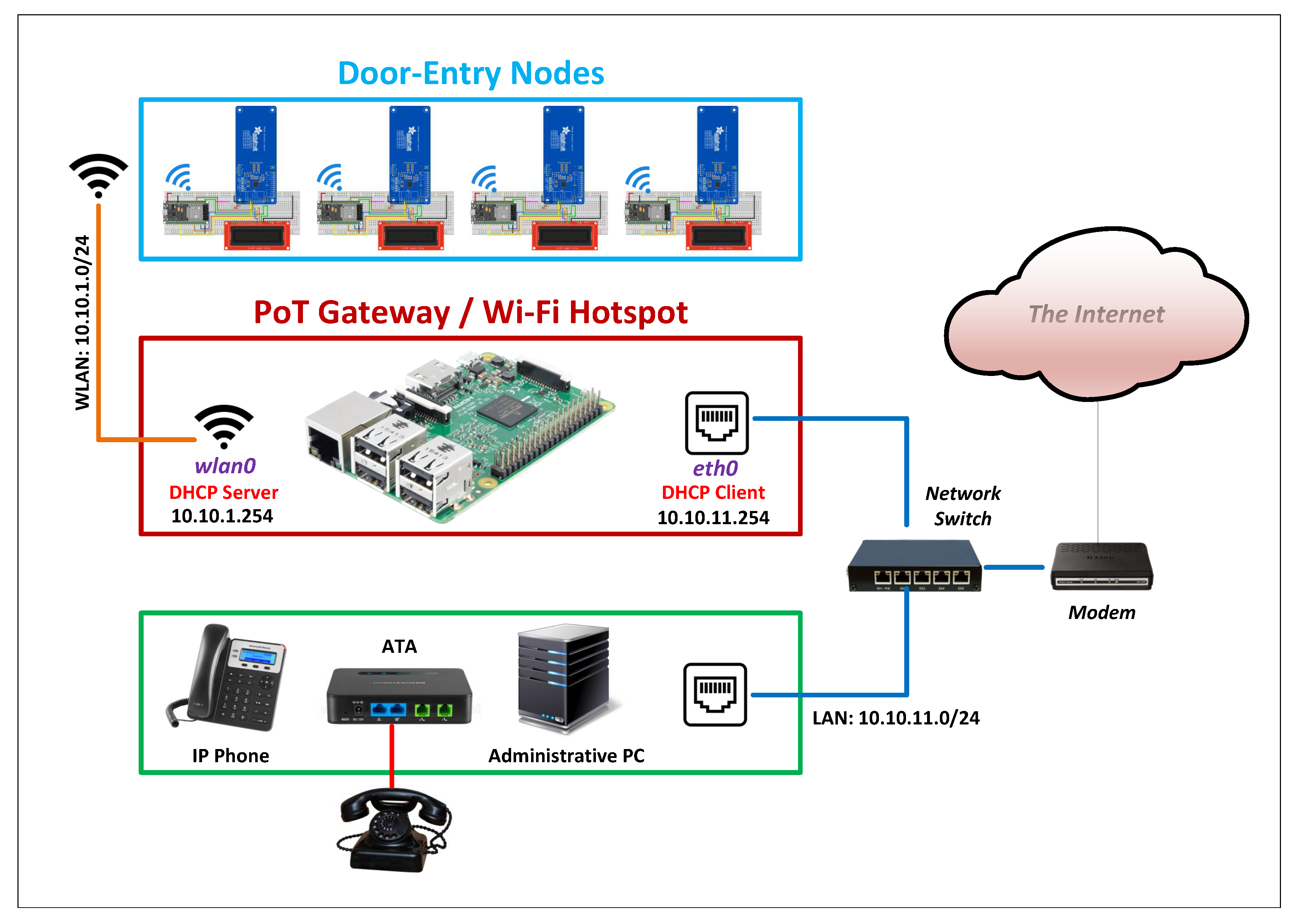
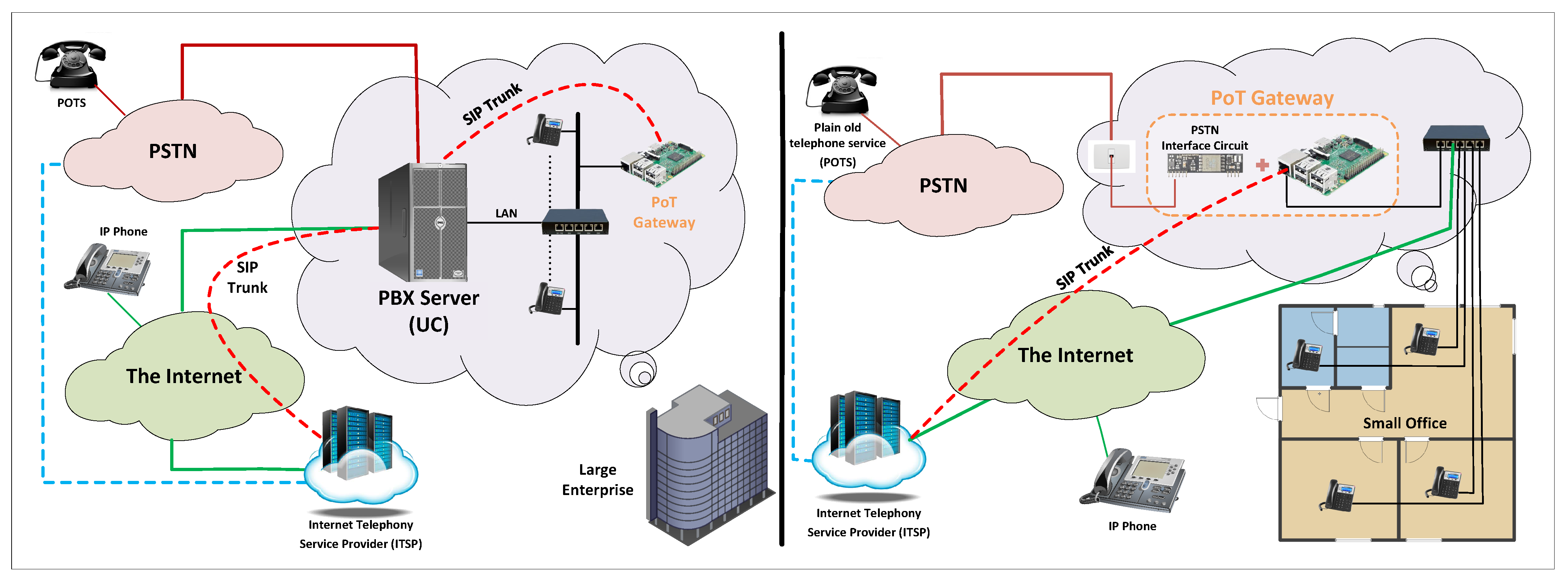
4.1. Overview
4.2. PoT Gateway
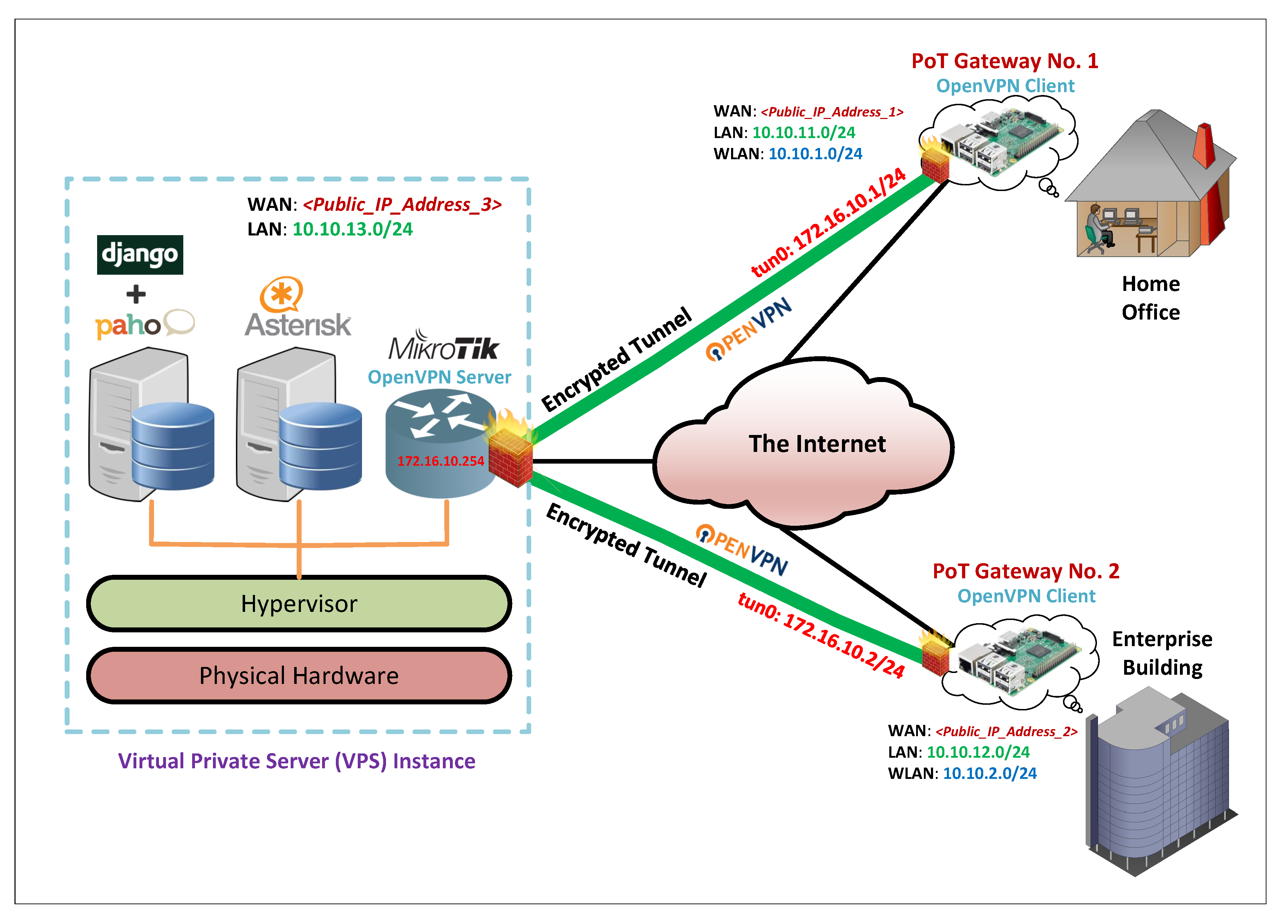
4.2.1. PoT Gateway as an OpenVPN Client
4.2.2. PoT Gateway as a Wi-Fi Access Point
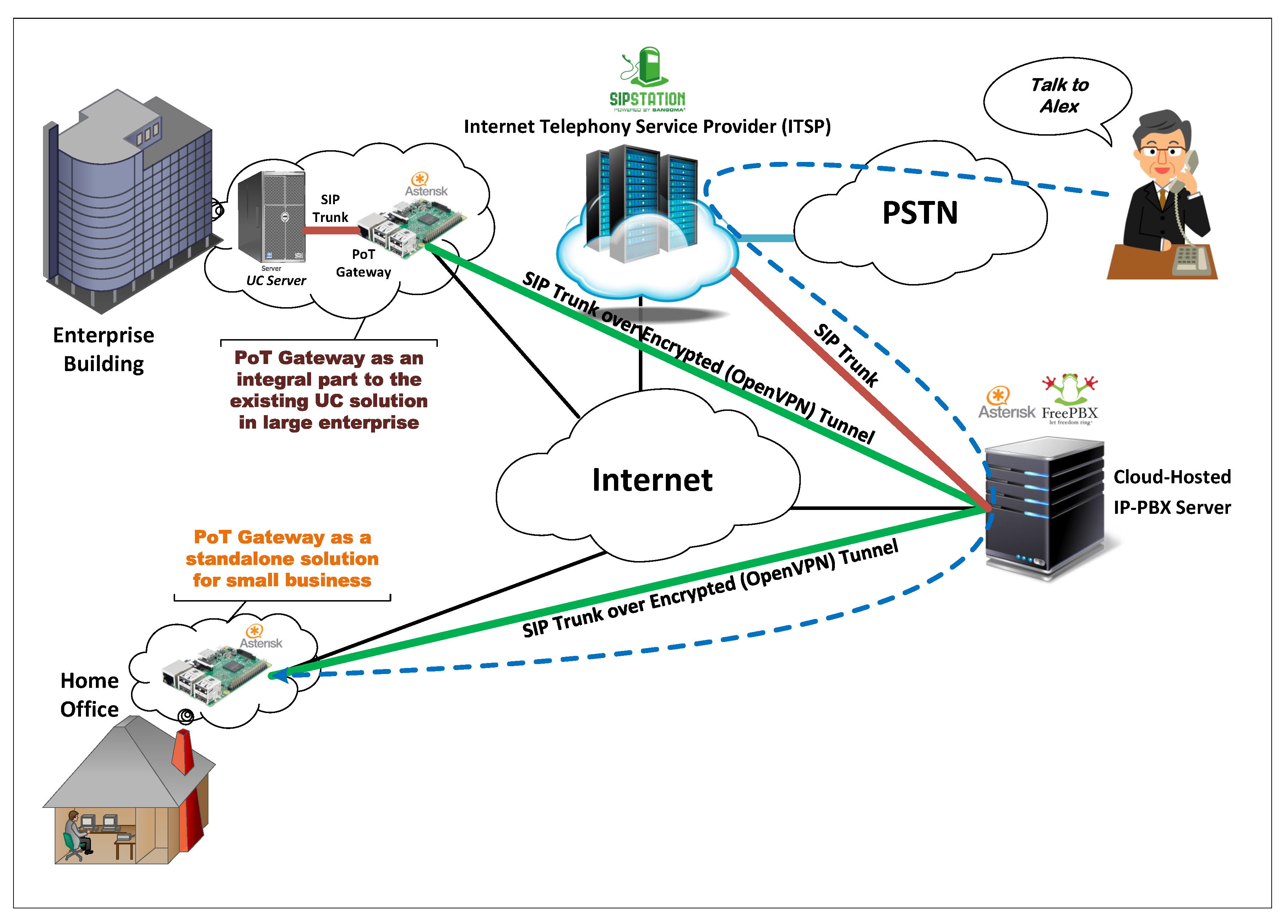
4.2.3. PoT Gateway as an IP-PBX Server
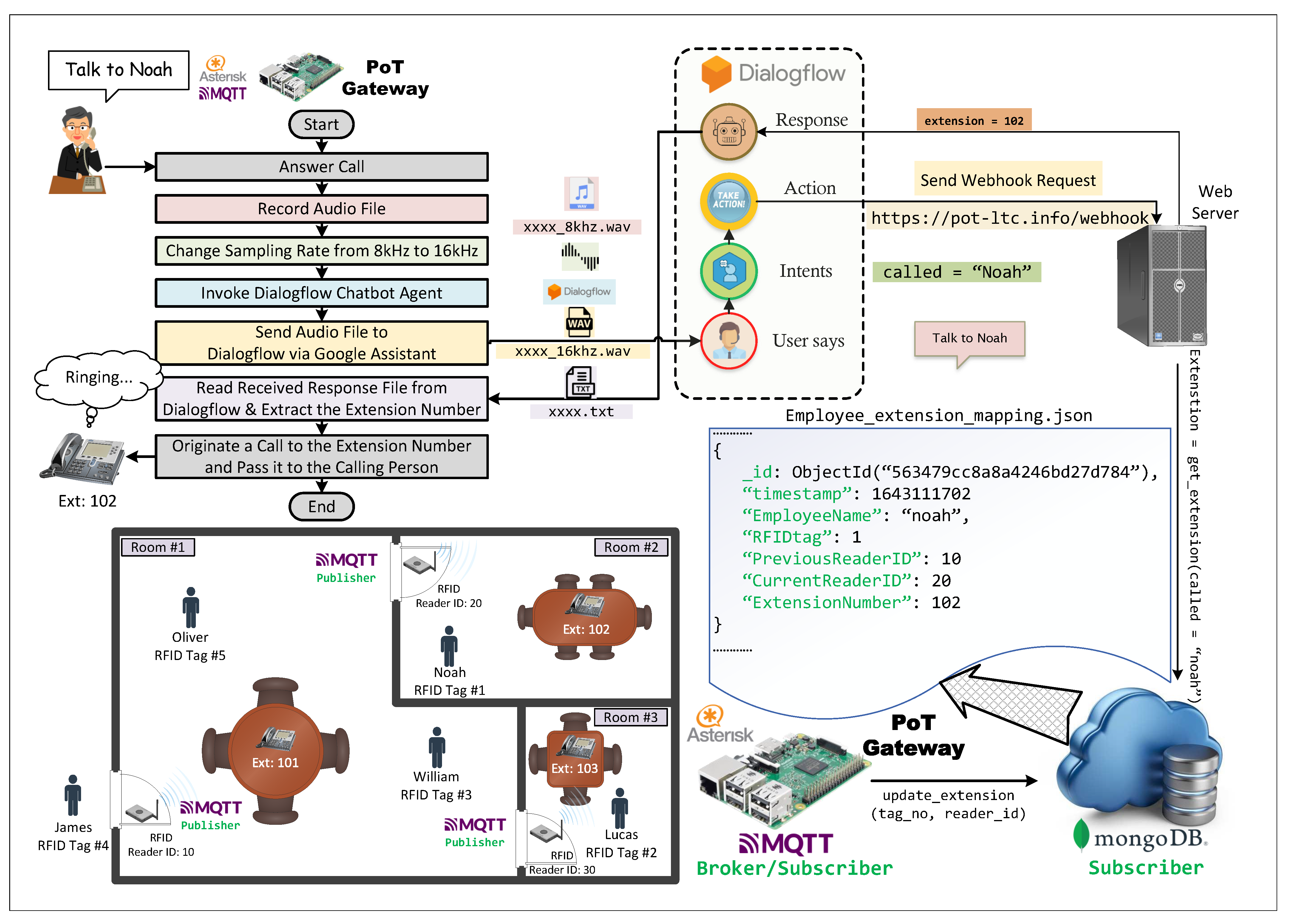
4.2.4. PoT Gateway and Dialogflow Integration
4.2.5. PoT Gateway as an MQTT Broker
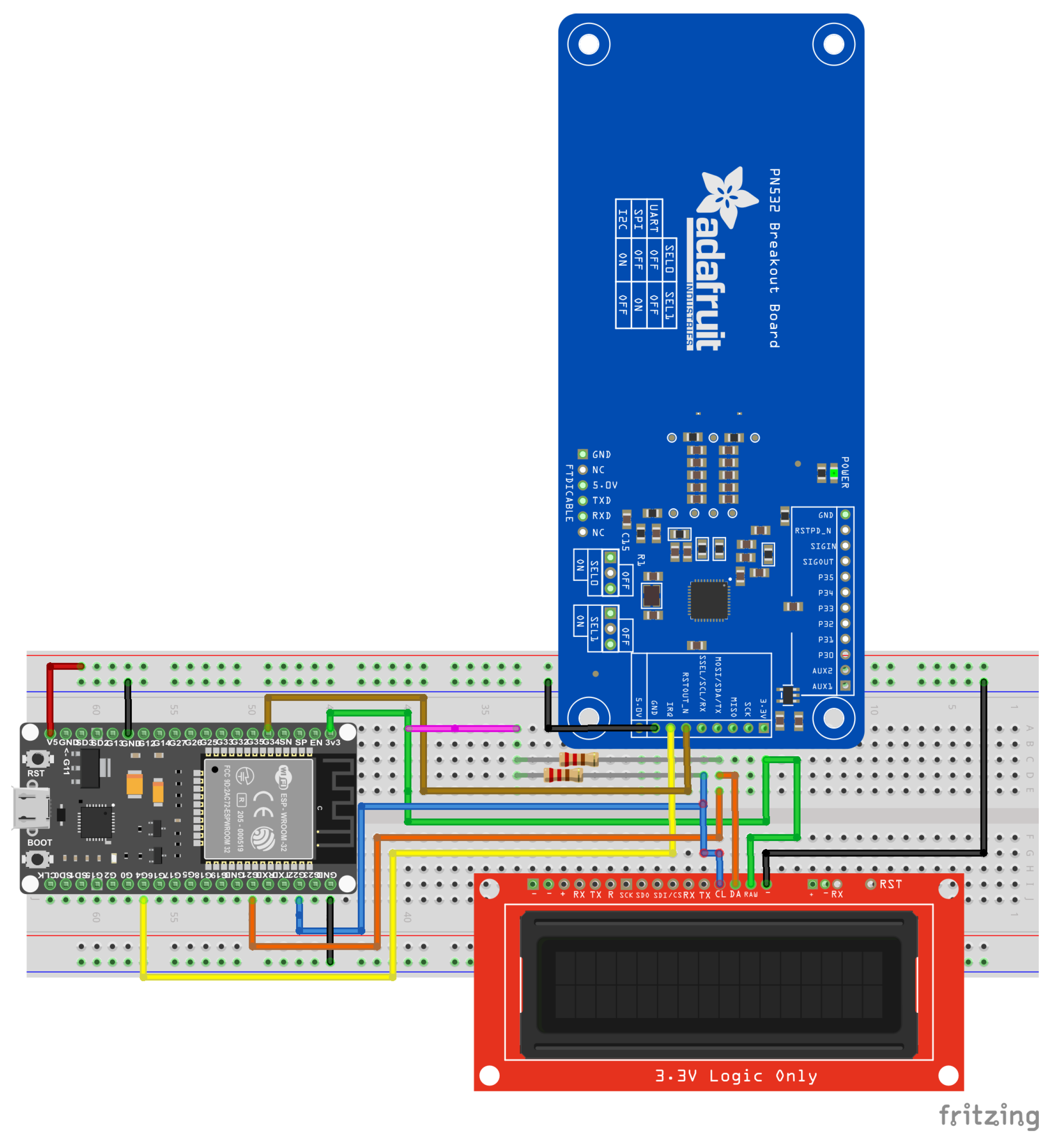
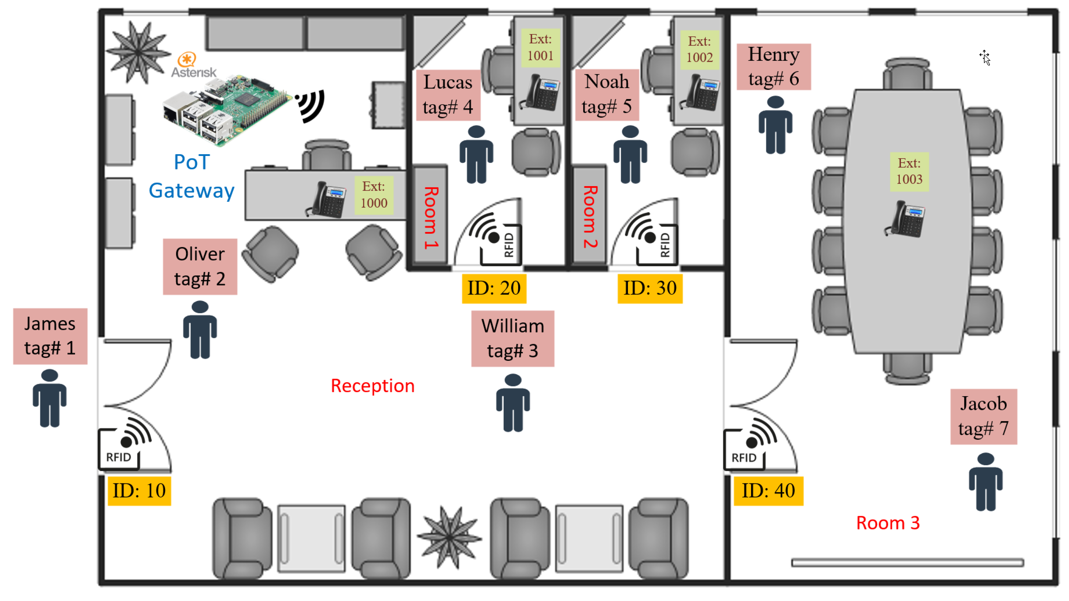
4.3. WiFi-Enabled RFID Door Entry Nodes
5. Feasibility Study
5.1. Performance Evaluation of Raspberry Pi Boards as Asterisk Server for LTC Applications
5.1.1. Overview
5.1.2. Methodology
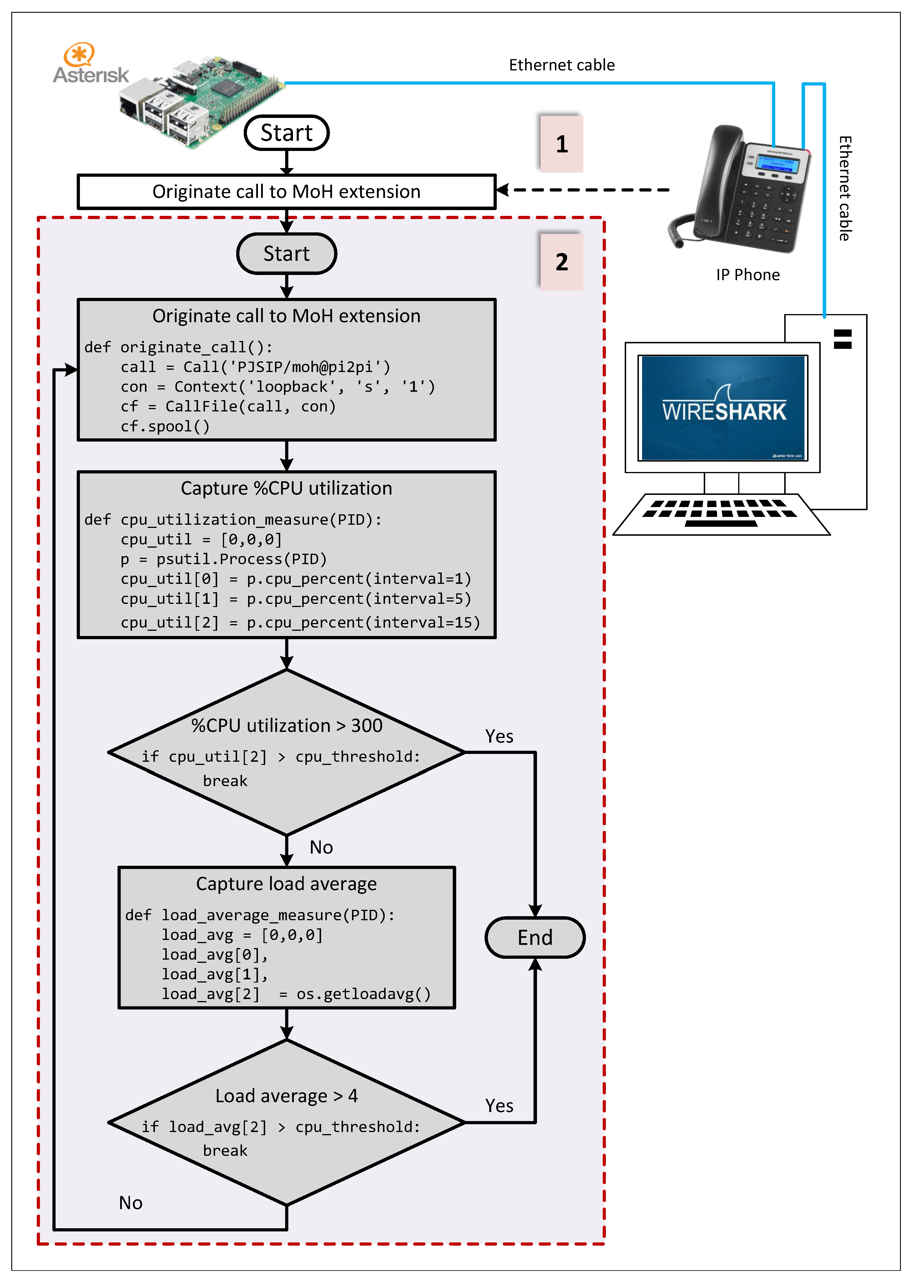
- A music-on-hold (MOH) extension was configured on the embedded Asterisk server of the PoT gateway. MOH maintained each originated call to that extension live until the calling party hung up the call. MOH allows one to programmatically originate an increasing number of simultaneous calls at the PoT gateway.
- After each call origination, the operating system metrics were captured by the testing script and compared against predefined threshold values defined in the script. Thresholds were set such that %CPU utilization <75% for single-core ARM boards and <300% for quad-core ARM boards (equivalent to 75% per core) and the load average (5 min interval) < 4. These thresholds aimed at: (1) protecting the embedded platform from potential hardware damage due to the excessive CPU utilization by the Asterisk process, (2) maintaining the responsiveness of the operating system in order to be able to carry out the evaluation measurements, (3) maintaining the VoIP call quality metrics at acceptable values, and (4) determining the maximum number of simultaneous VoIP calls that the embedded platform can gracefully serve.
- Another VoIP call was originated at the beginning of the test using an IP phone set. It called an MOH extension, and it was kept alive throughout the testing procedure. The traffic of this undergoing VoIP call was captured using Wireshark. The traffic capture was used to monitor the VoIP call quality metrics while originating an increasing number of VoIP calls during the test procedure to assure that both jitter and packet loss of the established VoIP calls still fall within the standard acceptable limits.

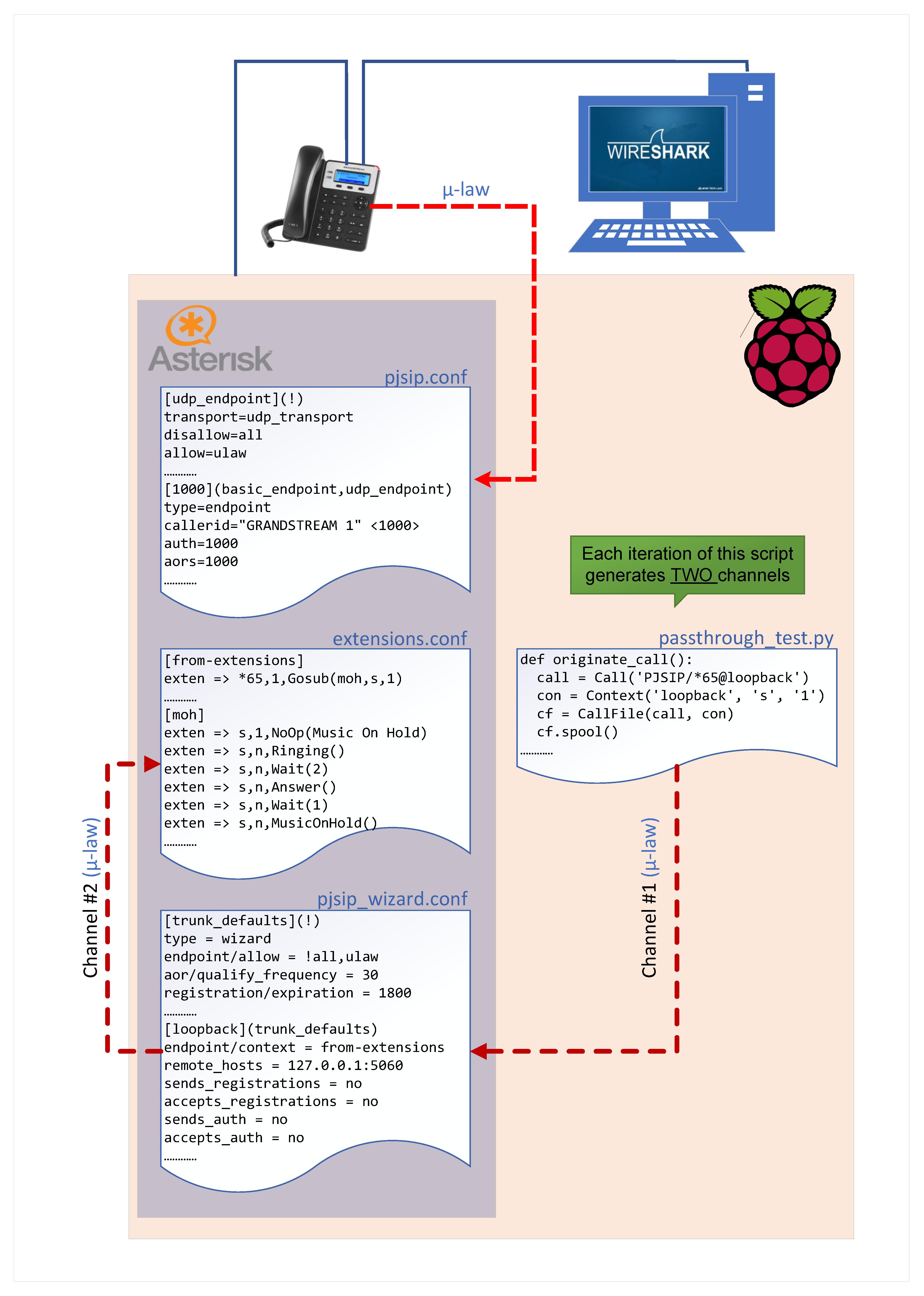
5.1.3. Passthrough VoIP Testing Overview
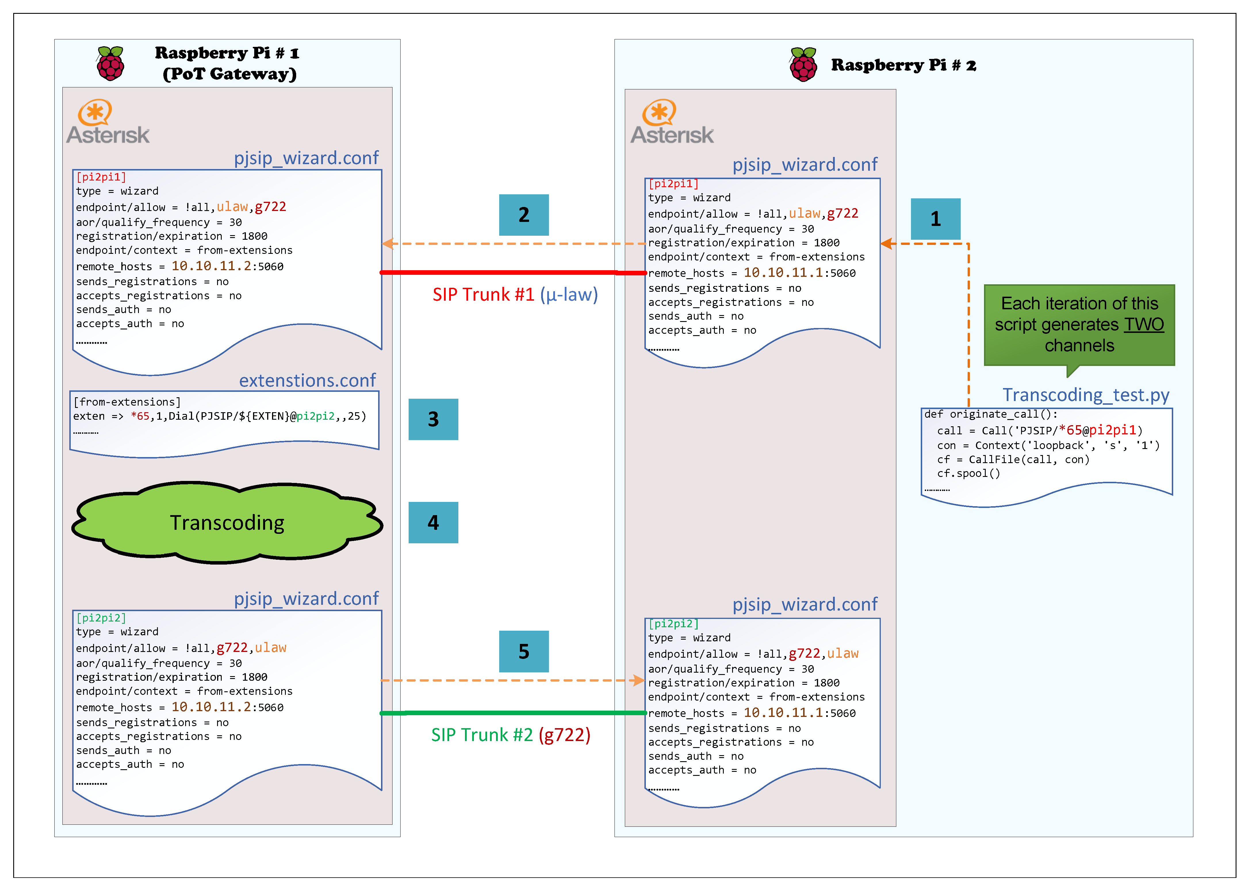
5.1.4. Transcoding VoIP Testing Overview
5.1.5. Results
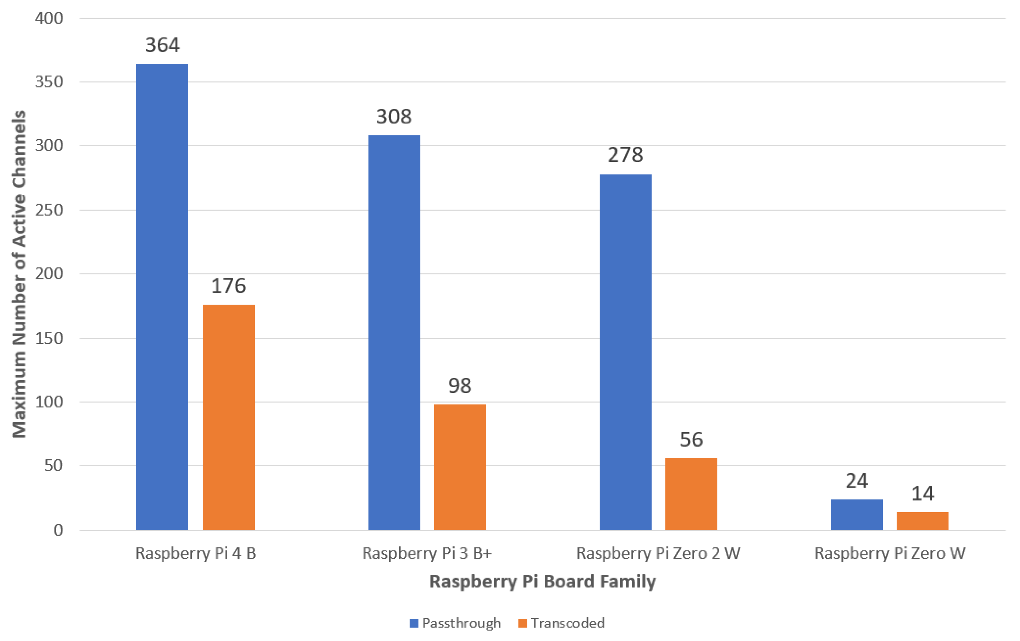
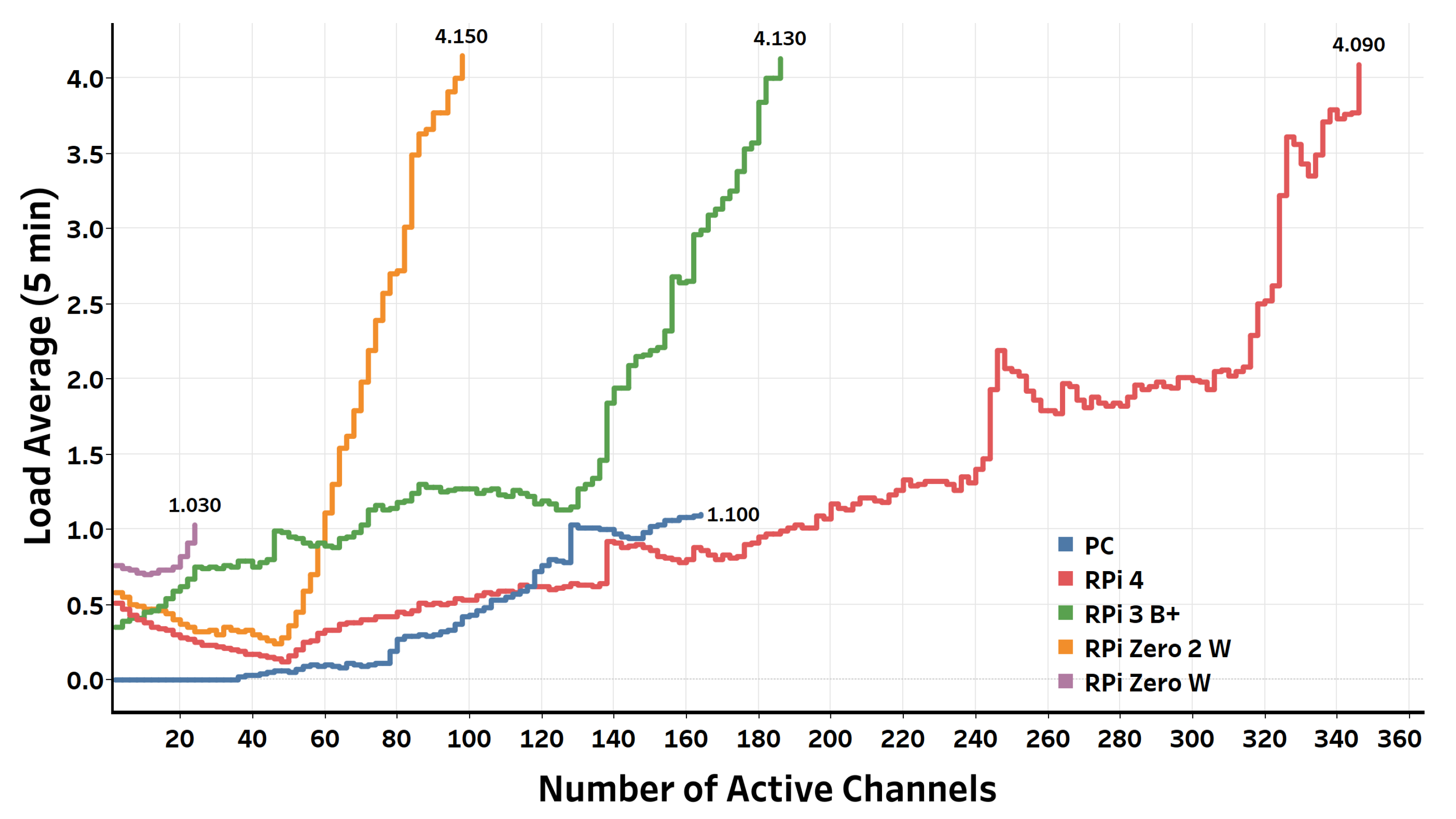
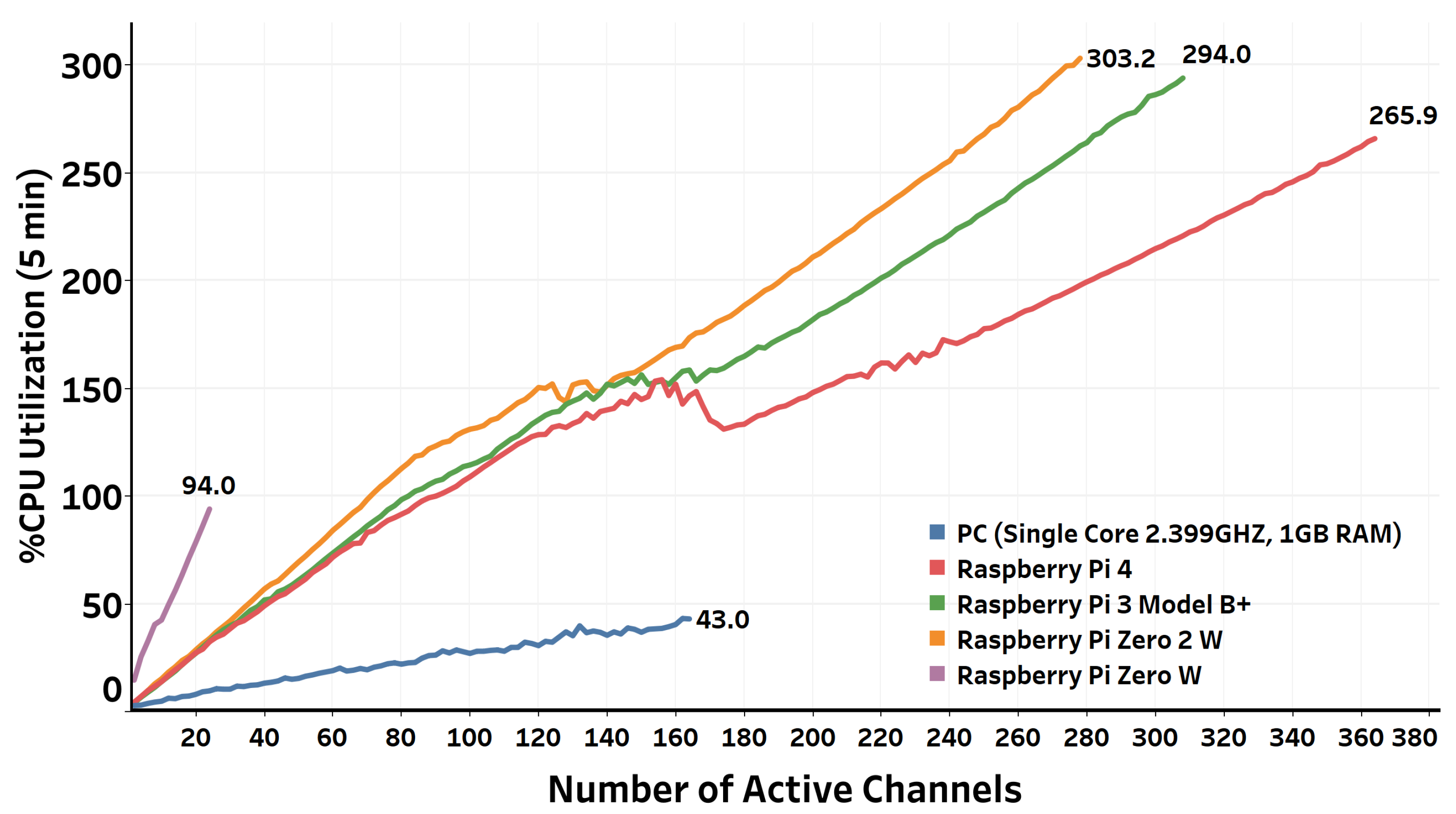
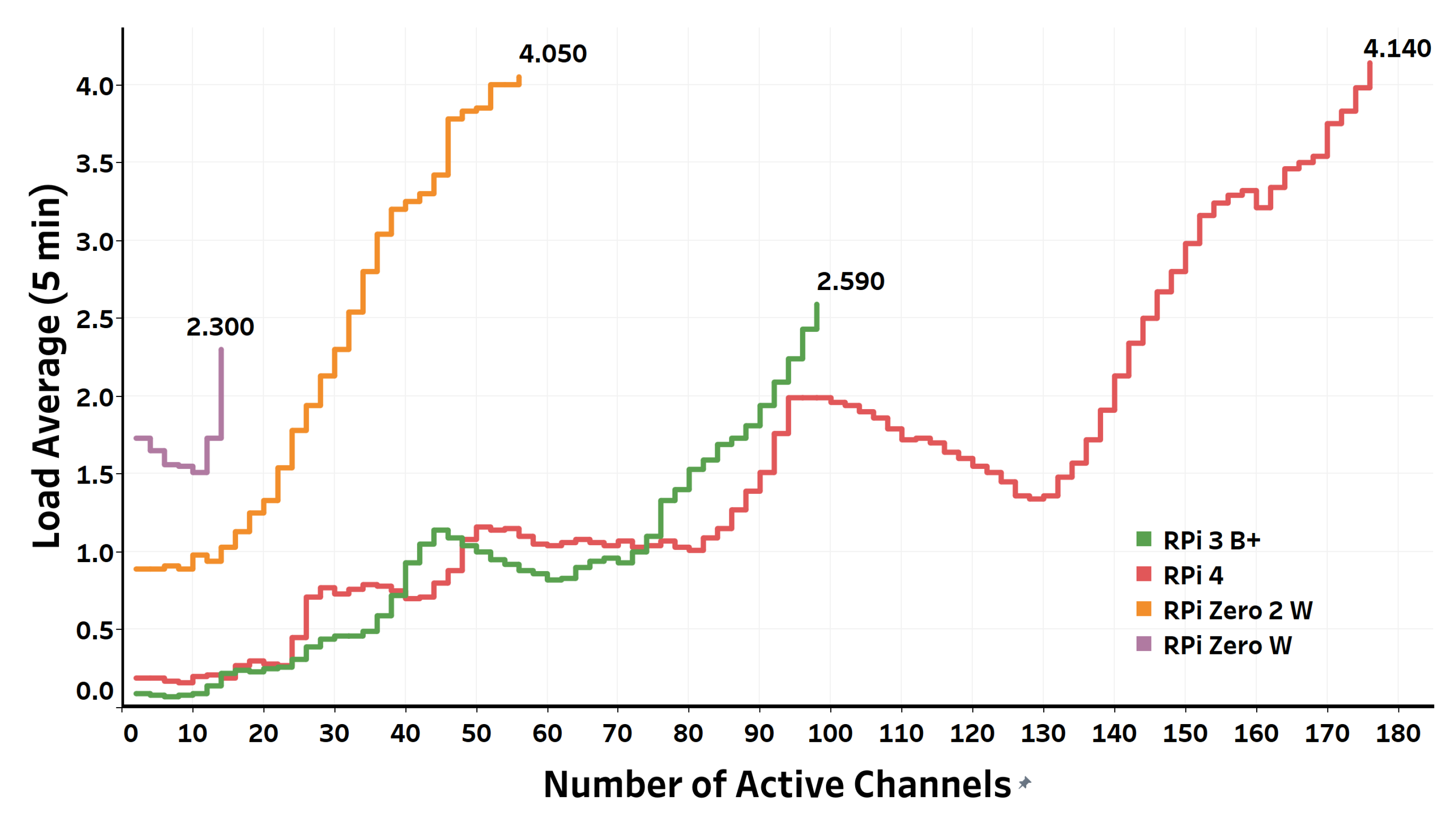
- Passthrough VoIP TestingThe performance evaluation of the Raspberry Pi boards when processing passthrough VoIP calls is shown in Figure 9 and Figure 10. The maximum numbers of simultaneous calls that the boards can gracefully handle are contrasted in Figure 11. Obviously, the maximum number of simultaneous calls is proportional to the board’s hardware specifications concerning the CPU core type, number of cores, and memory size.The results show that the least powerful model of the Raspberry Pi board family, namely, Raspberry Pi Zero W, can gracefully handle up to 24 active channels, which represents 12 simultaneous calls, after which the load average starts to exceed one. The CPU utilization of the board at this maximum number of simultaneous calls is 94%. On the other hand, Raspberry Pi 4 B, the current most powerful model of the Raspberry Pi board family, can gracefully handle up to 364 active passthrough channels (182 simultaneous calls) before the five minute load average starts to exceed four. The CPU utilization of the board at this number of simultaneous passthrough VoIP calls is 266% (66.5% per core). For other Raspberry Pi models, the maximum number of simultaneous calls lie between Raspberry Pi Zero W and Raspberry Pi 4 B based on the board’s hardware specifications.It is worth noting that Raspberry Pi Zero 2 W, the newest member of the Raspberry Pi boards family that launched in October 2021, has comparable performance to Raspberry Pi 3 B+. Raspberry Pi Zero 2 W comes at the same form factor as Raspberry Pi Zero W with a neglectable price increase ($19 CAD for Raspberry Pi Zero 2 W compared to $15 CAD for Raspberry Pi Zero W). However, Raspberry Pi Zero 2 W comes with a quad-core ARM Cortex A53 processor, in contrast to the single-core ARM11 that comes with Raspberry Pi Zero W. The results show that Raspberry Pi Zero 2 W can gracefully serve up to 278 active channels, whereas Raspberry Pi 3 B+ can gracefully serve 308 active channels. Therefore, Raspberry Pi Zero 2 W can ideally fit PoT applications where physical size and power consumption are the primary concerns.Except for Raspberry Pi Zero W, the performance of the Raspberry Pi boards used in the evaluation exceeded the VPS instance’s performance, whose specifications are listed in Table 1. Raspberry Pi Zero 2 W, for instance, can support an approximately 70% higher number of active channels than the number of active channels supported by the VPS. It is also worth noting that the boards can still serve more VoIP calls if we switch the threshold to the 15 min load average instead of the 5 min load average or raise the threshold limit a little bit beyond four. However, when the load average exceeds four, some VoIP call processes will be queued, waiting to be served by the operating system. This queuing affects the soft real-time constraints of VoIP, and hence it degrades the resulting quality measurements of the established VoIP calls.
- Transcoded VoIP TestingThe testing results of the simultaneous transcoded VoIP call capacity that the Raspberry Pi boards can safely process are shown in Figure 12 and Figure 13. In contrast to passthrough VoIP, transcoded VoIP is a process-intensive task that consumes many resources. Therefore, it is obviously expected that a smaller number of simultaneous transcoded VoIP calls can be afforded than simultaneous passthrough VoIP calls using the same platform. After using the same thresholds imposed on the testing algorithm when performing the passthrough testing, the results showed that the Raspberry Pi 4 B board, for example, can gracefully handle up to 176 active channels (88 simultaneous calls) before outpacing the thresholds. This represents 48% of passthrough VoIP calls the same board can afford. The ratio between the number of graceful transcoded VoIP calls to the number of graceful passthrough VoIP calls is proportional to the processing power of the board. The higher the processing power of the board, the higher the ratio of transcoded to passthrough VoIP calls the board can gracefully afford. Concerning the VoIP call quality metrics of established calls throughout the testing procedure, the results from Wireshark, as summarized in Table 2, show values of jitter and packet loss that all fall within the acceptable standardized limits of VoIP call quality metrics.
- Passthrough vs. Transcoded VoIP CallsIt is worth noting that the number of maximum simultaneous transcoded VoIP calls represents an extreme, where every originated call needs transcoding, of what actually happens in real situations. In most real cases, it is more likely that transcoding is avoided by enforcing particular audio codecs to be utilized by the communicating parties. Transcoding only happens when interconnecting with third-party providers, e.g., Internet Telephony Service Providers (ITSP), that operate other audio codecs to what we have already utilized. Therefore, we can posit that the maximum number of simultaneous VoIP calls that the Raspberry Pi boards can gracefully serve lays somewhere between the maximum number of passthrough VoIP calls and the maximum number of transcoded VoIP calls the specific platform can gracefully serve. The exact number of simultaneous VoIP calls depends on the application that defines the expected setup of the established VoIP calls.
5.2. LTC System for Large Enterprises
5.3. Entering and Exiting a Place
5.4. Multi-Site Support
6. Future Work
7. Conclusions
Author Contributions
Funding
Data Availability Statement
Conflicts of Interest
Abbreviations
| AI | Artificial Intelligence |
| AGI | Application Gateway Interface |
| API | Application Programming Interface |
| ATA | Analog Telephone Adapter |
| CoSIP | Constrained Session Initiation Protocol |
| CPU | Central Processing Unit |
| DBaaS | Database as a Service |
| DIY | Do-It-Yourself |
| IoT | Internet of Things |
| IP | Internet Protocol |
| ITSP | Internet Telephony Service Provider |
| IVR | Interactive Voice Response |
| LAN | Local Area Network |
| MCU | Microcontroller Unit |
| MQTT | Message Queuing Telemetry Transport |
| NFC | Near Field Communication |
| PBX | Private Branch Exchange |
| PoT | Phone of Things |
| PSTN | Public Switched Telephone Network |
| RFID | Radio Frequency Identification |
| RTP | Real Time Protocol |
| SDN | Software-Defined Networking |
| SIP | Session Initiation Protocol |
| SMS | Short Message Service |
| UC | Unified Communication |
| VoIP | Voice over Internet Protocol |
| VPN | Virtual Private Network |
| VPS | Virtual Private Server |
| WAN | Wide Area Network |
| WDS | Wireless Distribution System |
| WLAN | Wireless Local Area Network |
References
- Missed Calls: The Real Impact on Your Business. Available online: https://aircall.io/blog/customer-happiness/missed-calls/ (accessed on 20 January 2022).
- UK SMEs Lose ₤90m Due to Missed Calls. Available online: https://www.computerweekly.com/news/2240234997/UK-SMEs-lose-90m-because-of-missed-calls/ (accessed on 20 January 2022).
- The Co$t of a Missed Call: The Math Will Surprise You. Available online: https://www.mapcommunications.com/cost-missed-call/ (accessed on 20 January 2022).
- Stan, R. Automated Attendant Vs. Live Answering. Westchest. Cty. Bus. J. 2005, 40, 44. [Google Scholar]
- What Do Customers Really Think about Long Wait Times? Available online: https://www.icmi.com/resources/2017/what-do-customers-really-think-about-long-wait-times/ (accessed on 20 January 2022).
- Karademir, R.; Heves, E. Dynamic interactive voice response (IVR) platform. In Proceedings of the Eurocon 2013, Zagreb, Croatia, 1–4 July 2013; pp. 98–104. [Google Scholar] [CrossRef]
- Twilio: Communication APIs for SMS, Voice, Video & Authentication. Available online: https://www.twilio.com/ (accessed on 1 March 2022).
- Haytham, K.; Khalid, E. Phone of Things (PoT): Empowering IoT Systems Through VoIP Infrastructure and Voice Commands. In Proceedings of the 7th IEEE World Forum on the Internet of Things—WF-IoT 2021, New Orleans, LA, USA, 14 June–31 July 2021. [Google Scholar]
- Hillar, G.C. MQTT Essentials—A Lightweight IoT Protocol; Packt Pub.: Birmingham, UK, 2017; ISBN 9781787287815. [Google Scholar]
- Simone, C.; Marco, P.; Luca, V. CoSIP: A Constrained Session Initiation Protocol for the Internet of Things. In Advances in Service-Oriented and Cloud Computing; Springer: Berlin/Heidelberg, Germany, 2013; pp. 13–24. [Google Scholar]
- Andriopoulou, F.; Orphanoudakis, T.; Dagiuklas, T. IoTA: IoT Automated SIP-Based Emergency Call Triggering System for General eHealth Purposes. In Proceedings of the 2017 IEEE 13th International Conference on Wireless and Mobile Computing, Networking and Communications (WiMob), Rome, Italy, 9–11 October 2017; IEEE: Piscataway, NJ, USA, 2017; pp. 362–369. [Google Scholar]
- Sangkong, J.; Ongtang, M. Smart VoIP Postbox with Confirmation Receipt Using IoT Technology. In Proceedings of the 2017 International Conference on Industrial Design Engineering, Dubai, United Arab Emirates, 29–31 December 2017; ACM: New York, NY, USA, 2017; pp. 71–75. [Google Scholar]
- Melo, D.D.F.; Lage, E.D.S.; Rocha, A.V.; Cardoso, B.D.J. Improving the Consumption and Water Heating Efficiency in Smart Buildings. In Proceedings of the 2017 13th International Conference and Expo on Emerging Technologies for a Smarter World (CEWIT), Stony Brook, NY, USA, 7–8 November 2017; IEEE: Piscataway, NJ, USA, 2017; pp. 1–6. [Google Scholar]
- López, J.P.B.; Pérez, Y.M. Integration of Asterisk IP-PBX with ESP32 Embedded System for Remote Code Execution. Multidiscip. Digit. Publ. Inst. Proc. 2019, 21, 38. [Google Scholar]
- Hernandez, L.; Ospina, M. Scheme and Creation of a Prototype for the Supervision of Lights and Electronic Devices with a PBX, Using a WLAN Solution Based on IoT. In Proceedings of the 2019 IEEE Colombian Conference on Communications and Computing (COLCOM), Barranquilla, Colombia, 5–7 June 2019; IEEE: Piscataway, NJ, USA, 2019; pp. 1–6. [Google Scholar]
- Elshamy, E.M.; Hussein, A.I.; Hamed, H.F.; Abdelghany, M.A.; Kelash, H.M. Voice over internet protocol voicemail security system using two factor authentication and biometric prints with new efficient hybrid cryptosystem. Multimed Tools Appl. 2021, 80, 9877–9893. [Google Scholar] [CrossRef]
- Cold Call Sales Voicemail Scripts That Get Callbacks. Available online: https://blog.zoominfo.com/cold-sales-voicemails/ (accessed on 20 January 2022).
- James, D.; Michael, S. SMS Notifications for Missed Calls: Expanding Mobility for TDM Environments. In Proceedings of the 3rd Annual Conference on Research in Information Technology, Atlanta, GA, USA, 15–18 October 2014; ACM: New York, NY, USA, 2014; pp. 71–74. [Google Scholar]
- NNurhalim, I.; Gunawan, D. PSTN VoIP Application Support System Design using mobile Short Message Service (SMS): Case Study of PSTN VoIP Missed Call Notification to mobile phone by SMS. In Proceedings of the 2011 International Conference on Electrical Engineering and Informatics, Bandung, Indonesia, 17–19 July 2011; pp. 1–4. [Google Scholar] [CrossRef]
- Aberethy, M.; Grigsby, T.; Paolini, M.; Potluri, L. Missed Call Integration with Voicemail and Granular Access to Voicemail. US Patent 8,594,634, 26 November 2013. [Google Scholar]
- Understanding the Impact of Voicemail. Available online: https://www.answer365.ca/blog/102-understanding-the-impact-of-voicemail.html (accessed on 20 January 2021).
- Raspberry Pi: Teach, Learn, and Make with Raspberry Pi. Available online: https://raspberrypi.org/ (accessed on 20 January 2022).
- Muhammad, I.; Kovacic, B. Analysis of Security Virtual Private Network (VPN) Using OpenVPN. Int. J.-Cyber-Secur. Digit. Forensics 2019, 8, 58–65. [Google Scholar]
- Vultr: SSD VPS Servers, Cloud Servers and Cloud Hosting. Available online: https://www.vultr.com (accessed on 20 January 2022).
- Kamal, B.; Abdeslam, E.; Abdelbaki, E.E. Software-Defined Networking (SDN): A Survey. Secur. Commun. Netw. 2016, 18, 5803–5833. [Google Scholar]
- Asterisk: Open Source Communications Software. Available online: https://asterisk.org/ (accessed on 20 January 2022).
- Raspberry Pi Downloads, Software for the Raspberry Pi. Available online: https://www.raspberrypi.org/downloads/ (accessed on 20 January 2022).
- Jabel, A.N.; Manickam, S.; Ramdas, S. A Study of SIP Trunk Security and Challenges. In Proceedings of the 2012 IEEE International Conference on Electronics Design, Systems and Applications (ICEDSA), Kuala Lumpur, Malaysia, 5–6 November 2021; IEEE: Piscataway, NJ, USA, 2012; Volume 10, pp. 239–243. [Google Scholar]
- Maldonado, J.A.V.; Cuadra, J.A.G. Natural Language Interface to Database Using the DialogFlow Voice Recognition and Text Conversion API. In Proceedings of the 8th International Conference On Software Process Improvement (CIMPS), Leon, Mexico, 23–25 October 2019; pp. 1–10. [Google Scholar] [CrossRef]
- Simionovich, N. Asterisk Gateway Interface 1.4 and 1.6 Programming: Design and Develop Asterisk-Based VoIP Telephony Platforms and Services Using PHP and PHPAGI; Packt Pub.: Birmingham, UK, 2009. [Google Scholar]
- Managed MongoDB Hosting|Database-as-a-Service|MongoDB. Available online: https://www.mongodb.com/cloud/atlas (accessed on 20 January 2022).
- Sharifi, H.; Ismail, H.S.; Qiu, J.; Tavani, S.N. RFID in the Warehouse: A Literature Analysis (1995–2010) of Its Applications, Benefits, Challenges and Future Trends. Int. J. Prod. Econ. 2013, 10, 409–430. [Google Scholar]
- Szigeti, T.; Hattingh, C. End-to-End QoS Network Design: Quality of Service in LANs, WANs, and VPNs, 1st ed.; Cisco Press: Indianapolis, IN, USA, 2004. [Google Scholar]


| Property | Configuration |
|---|---|
| Server Location | Toronto, Canada |
| Server Type | Linux, Ubuntu 18.04 × 64 |
| No. of CPUs | 1 |
| RAM | 1 GB |
| Storage | 25 GB SSD |
| Bandwidth | 500 GB |
| Cost | $5 USD/month |
| RPi 4 B | RPi 3 B+ | RPi Z 2 W | RPi Z W | |||||
|---|---|---|---|---|---|---|---|---|
| Passthrough | Trans. | Passthrough | Trans. | Passthrough | Trans. | Passthrough | Trans. | |
| Forward (Phone-to-RPi) | ||||||||
| Max jitter (milliseconds) | 9.35 | 10.49 | 11.87 | 10.97 | 12.05 | 13.85 | 15.33 | 16.02 |
| Mean jitter (milliseconds) | 7.08 | 6.45 | 8.09 | 6.88 | 9.96 | 10.13 | 11.58 | 13.69 |
| RTP Packets | 132,486 | 115,715 | 111,460 | 65,414 | 101,623 | 37,211 | 8688 | 5058 |
| Expected | 132,486 | 115,715 | 111,460 | 65,414 | 101,623 | 37,211 | 8688 | 5058 |
| Packet loss (%) | 0.0 | 0.0 | 0.0 | 0.0 | 0.0 | 0.0 | 0.0 | 0.0 |
| Reverse (RPi-to-Phone) | ||||||||
| Max jitter (milliseconds) | 5.07 | 5.98 | 5.90 | 8.43 | 8.85 | 9.32 | 10.02 | 20.36 |
| Mean jitter (milliseconds) | 0.65 | 0.68 | 0.70 | 0.73 | 0.98 | 0.85 | 0.90 | 3.5 |
| RTP Packets | 132,450 | 115,624 | 111,365 | 65,369 | 101,577 | 37,188 | 8610 | 5049 |
| Expected | 132,450 | 115,624 | 111,365 | 65,369 | 101,577 | 37,188 | 8610 | 5049 |
| Packet loss (%) | 0.0 | 0.0 | 0.0 | 0.0 | 0.0 | 0.0 | 0.0 | 0.0 |
| Reader ID (t − 1) | Reader ID (t) | Location | Extension No. | Remark |
|---|---|---|---|---|
| - | 10 | Reception | 1000 | Coming |
| 10 | 10 | Reception | 1000 | Leaving (Fallback) |
| 10 | 20 | Room 1 | 1001 | Entering Room 1 |
| 10 | 30 | Room 2 | 1002 | Entering Room 2 |
| 10 | 40 | Room 3 | 1003 | Entering Room 3 |
| 20 | 10 | Reception | 1000 | Leaving (Fallback) |
| 20 | 20 | Reception | 1000 | Entering Reception |
| 20 | 30 | Room 2 | 1002 | Entering Room 2 |
| 20 | 40 | Room 3 | 1003 | Entering Room 3 |
| 30 | 10 | Reception | 1000 | Leaving (Fallback) |
| 30 | 20 | Room 1 | 1001 | Entering Room 1 |
| 30 | 30 | Reception | 1000 | Entering Reception |
| 30 | 40 | Room 3 | 1003 | Entering Room 3 |
| 40 | 10 | Reception | 1000 | Leaving (Fallback) |
| 40 | 20 | Room 1 | 1001 | Entering Room 1 |
| 40 | 30 | Room 2 | 1002 | Entering Room 2 |
| 40 | 40 | Reception | 1000 | Entering Reception |
| No. | Name | RFID Tag No. | Reader ID (t − 1) | Reader ID (t) | Location | Extension No. |
|---|---|---|---|---|---|---|
| 1 | James | 1 | 10 | 10 | Not Exist | 1000 (Fallback) |
| 2 | Oliver | 2 | - | 10 | Reception | 1000 |
| 3 | William | 3 | 20 | 20 | Reception | 1000 |
| 4 | Lucas | 4 | 10 | 20 | Room 1 | 1001 |
| 5 | Noah | 5 | 20 | 30 | Room 2 | 1002 |
| 6 | Henry | 6 | 10 | 40 | Room 3 | 1003 |
| 7 | Jacob | 7 | 30 | 40 | Room 3 | 1003 |
| 8 | Lucas | 4 | - | 20 | Invalid | 1000 (Fallback) |
Publisher’s Note: MDPI stays neutral with regard to jurisdictional claims in published maps and institutional affiliations. |
© 2022 by the authors. Licensee MDPI, Basel, Switzerland. This article is an open access article distributed under the terms and conditions of the Creative Commons Attribution (CC BY) license (https://creativecommons.org/licenses/by/4.0/).
Share and Cite
Khalil, H.; Elgazzar, K. Location Transparency Call (LTC) System: An Intelligent Phone Dialing System Based on the Phone of Things (PoT) Architecture. Future Internet 2022, 14, 111. https://doi.org/10.3390/fi14040111
Khalil H, Elgazzar K. Location Transparency Call (LTC) System: An Intelligent Phone Dialing System Based on the Phone of Things (PoT) Architecture. Future Internet. 2022; 14(4):111. https://doi.org/10.3390/fi14040111
Chicago/Turabian StyleKhalil, Haytham, and Khalid Elgazzar. 2022. "Location Transparency Call (LTC) System: An Intelligent Phone Dialing System Based on the Phone of Things (PoT) Architecture" Future Internet 14, no. 4: 111. https://doi.org/10.3390/fi14040111
APA StyleKhalil, H., & Elgazzar, K. (2022). Location Transparency Call (LTC) System: An Intelligent Phone Dialing System Based on the Phone of Things (PoT) Architecture. Future Internet, 14(4), 111. https://doi.org/10.3390/fi14040111