Article

An In-Network Cooperative Storage Schema Based on Neighbor Offloading in a Programmable Data Plane

1
National Network New Media Engineering Research Center, Institute of Acoustics, Chinese Academy of Sciences, No. 21, North Fourth Ring Road, Haidian District, Beijing 100190, China
2
School of Electronic, Electrical and Communication Engineering, University of Chinese Academy of Sciences, No. 19(A), Yuquan Road, Shijingshan District, Beijing 100049, China
*
Author to whom correspondence should be addressed.
Future Internet 2022, 14(1), 18; https://doi.org/10.3390/fi14010018
Submission received: 13 December 2021 / Revised: 26 December 2021 / Accepted: 28 December 2021 / Published: 30 December 2021
(This article belongs to the Special Issue Recent Advances in Information-Centric Networks (ICNs))

Abstract

:
In scientific domains such as high-energy particle physics and genomics, the quantity of high-speed data traffic generated may far exceed the storage throughput and be unable to be in time stored in the current node. Cooperating and utilizing multiple storage nodes on the forwarding path provides an opportunity for high-speed data storage. This paper proposes the use of flow entries to dynamically split traffic among selected neighbor nodes to sequentially amortize excess traffic. We propose a neighbor selection mechanism based on the Local Name Mapping and Resolution System, in which the node weights are computed by combing the link bandwidth and node storage capability, and determining whether to split traffic by comparing normalized weight values with thresholds. To dynamically offload traffic among multiple targets, the cooperative storage strategy implemented in a programmable data plane is presented using the relative weights and ID suffix matching. Evaluation shows that our proposed schema is more efficient compared with end-to-end transmission and ECMP in terms of bandwidth usage and transfer time, and is beneficial in big science.

1. Introduction

In many scientific disciplines, a huge amount of data is being generated. In the X-ray Free Electron Laser device (XFEL), the average data rate has reached more than 2 GB/s, the peak rate has reached 100 GB/s, and the data storage capacity has exceeded 100 PB [1]. Significant challenges exist in the collection and storage of data by large scientific facilities. The ever-increasing data generation speed and the sheer quantity of data require effective tools to collect and filter the data, save the data through high-speed networks, and prevent the loss of valuable data. Due to the storage capability limitations of existing computer systems, it is too late to completely record and save rapidly generated data [2]. However, there may be an opportunity for more nodes to participate in storage via high-speed networks. In addition, a large amount of data not only needs to be stored properly, but also needs to be able to be efficiently accessed. Due to the increase in the quantity of data, it is becoming increasingly difficult to read and move data. To deal with these challenges, a common approach is to build a data center on site, connect the experimental station with an optical fiber network/InfiniBand, and equip the data center with high-speed storage and computing equipment (CPU, GPU) for scientific computing. However, a bottleneck remains in network throughput and storage capacity in these solutions, because they still use end-to-end transmission, and provide limited improvements using the shortest routing path or multiple paths in the transport layer. Furthermore, distributing the large quantity of raw data and making this data available to scientists around the world in a scalable manner are additional typical challenges.
Recently, Named Data Networking (NDN) [3,4] and big science communities have combined cache and forwarding strategies, and used the cache capability to accelerate the distribution and management for big science experimental data [5,6,7,8,9]. In [5], the author proposes the federating of distributed catalog systems that store and manage NDN names to increase the speed of discovery of desired data. The work of [6] presented a preliminary study addressing opportunities and challenges to enable NDN-based intelligent data retrieval in networks for high-energy physics (HEP). However, these studies focused on the management of a huge quantity of scientific data and data retrieval, and rarely involved the persistent storage of collected data in networks.
As a result of the development of networking and storage, the forwarding rate of the interface commonly exceeds the storage bandwidth in a single network node. However, other switches in the network can have high speeds and large persistent storage capabilities. To better handle high-speed data injection, multiple switches can cooperate to store heavy data storage traffic. Using the network as a means of storage, the data can be stored along the path, which facilitates edge processing and avoids sending data to the cloud for reading, processing, and analysis, thus saving network bandwidth and increasing the responsiveness of the applications. However, no research has been conducted on directly using the network as a form of permanent storage, which would allow producers to simply offload their data to the network and let the network manage the storage and access to data.
This paper proposes the realization of data storage in the forwarding process, and to cooperatively offload the data beyond the local storage capacity to neighbor storage nodes. The main contributions of our work are as follows:
(1)
To address high-speed data storage, we proposed an in-network storage service node structure to support cooperative storage in neighbor nodes, and designed an identifier (ID)-based cooperative storage protocol.
(2)
To support locally cooperative storage and the discovery of more in-network storage service nodes, we proposed a neighbor selection mechanism based on the Local Name Mapping and Resolution System, in which the node weights are computed by combining the link bandwidth and node storage capability, and determining whether to split traffic by comparing normalized weight values with thresholds.
(3)
To dynamically split the traffic among multiple targets, the cooperative storage strategy implemented in a programmable data plane is presented using the relative weights and ID suffix matching. Evaluation shows that our proposed schema is more efficient compared with end-to-end transmission and ECMP [10] in term of bandwidth usage and transfer time.
The remainder of the paper is organized as follows. In Section 2, we review the related work in distributed storage, edge storage, current scientific data management systems, and NDN-based big science. The overall system design and supported protocol are introduced in Section 3. Section 4 presents our core cooperative storage mechanism. Then, the experimental results and analysis are shown in Section 5. Finally, conclusions of this paper are presented in Section 6.

2. Background

Numerous studies have been conducted on distributed storage in academia and industry, but most of storage systems are constructed at the application layer. As a result of the recent development of the programmable network technology, solutions have been developed that use in-network computing to offload part of the storage function into the network [11]. In this section, we present a comprehensive review of the current relevant literature.

2.1. Distributed Storage

Existing data storage services, such as HDFS [12], GFS [13], and CEPH [14], are mostly clustering systems in data centers. Due to monitoring of the load status of each storage node, data requests are routed to storage nodes by centralized scheduling to support load balancing. When load balancing is performed, generally only the storage space of the node is considered, and the network link usage between the requester and the node is ignored. In a CDN network, contents are spread based on requests and the popularity of contents. It dispatches requests to the nearest content replica via central scheduling, and resolves download bottlenecks through caching, and is not suitable for real-time data injecting. The cloud storage system is a core cloud-based service offered by most cloud providers, such as Google, Amazon, and Microsoft. However, cloud storage system is located far from users, resulting in a high response delay for applications. Moreover, a massive amount of data generated by IoT devices places significant pressure on the core network for its transmission to remote clouds. For this purpose, providing storage as close to users as possible or at the edge of the network is beneficial.

2.2. Storage at the Edge

The existing literature tackles the problem of edge data storage with strategies for the optimal placement of data storage, aiming to maximize the QoS offered by the edge [15,16]. In [17], the authors explored the advantages and challenges of edge data storage to reduce the pressure on the core network from the massive data generated by IoT devices when transferring these data to cloud storage. In [18], the authors developed and assessed a preliminary design for the management of popular data at the edge. The Reverse-CDN proposed an architectural design vision to combine both Fog Computing and Information Centric Networking (ICN) to process IoT data locally at the edge [19]. Decentralized content-addressed storage systems, such as IPFS [20], are essentially the product of an end-to-end communication mechanism where retrieval of data needs to first establish a connection.

2.3. Current Scientific Data Management Systems

Scientific communities have designed and developed various customized data management software packages to satisfy their needs. The climate community has developed ESGF [21] to manage CMIP5 [22] data. Similarly, the HEP community uses Xrootd [23] for its data access and storage [8]. These applications are all based on IP networking protocols, inherit the defects caused by the end-to-end communication principle of the existing IP network, and cannot provide an appropriate network service model to efficiently facilitate data discovery and retrieval.

2.4. NDN Based Big Science

In [7], the authors studied federated distributed catalog systems that store and manage NDN names to support climate data discovery in multiple domains using Named Data Networking. The authors in [8] use a VIP forwarding and caching mechanism [24] and designed an NDN-based Large Hadron Collider (LHC) network. This work shows that NDN with VIP forwarding and caching can achieve a large reduction in the average delay per chunk compared to a no-caching case in the simulated LHC network [8]. The work of [9] uses NDN-based primitives to present a design of the deadline-based data transfer protocol for reserved bandwidth data transfers. However, these studies focused on the metadata management of huge scientific data or complex scientific workflow, rarely involved the collected data persistence storage.
Combined with the existing work above, we propose the use of in-network storage to support high-speed scientific data collection, retrieval, and sharing via ICN architecture. We designed the structure of an in-network storage service node, and cooperatively store the data based on an ID protocol.

3. Proposed System Architecture

3.1. System Architecture

To better implement a new network architecture or network protocol on the existing network infrastructure, and reduce deployment or upgrade costs, the system architecture is usually required to be compatible with the existing network infrastructure [25]. To be compatible with the existing network infrastructure, the proposed in-network storage solution is based on name resolution ICN where ID is resolved into an address for routing. Under the architecture of routing and forwarding in ICN based on control and user plane separation, the ID/IP integrated ICN reconstruction module has the capability of asking the Global Name Mapping and Resolution System (GNMRS) or Local Name Mapping and Resolution System (LNMRS) for resolving an ID to address(es) [26]. The ID/IP integrated ICN reconstruction module can also process the address(es) in the packet according to the rules and regulations generated by the local computing module. The rules and regulations may include deleting some addresses from the address field, or changing the destination address [27]. Then, a new ID/IP integrated ICN packet is reconstructed and finally forwarded by the IP forwarding module [27]. The focus of the current study is extending the local computing module to cooperatively support storing data chunk traffic in neighbors.
The designed in-network storage process is as follows:
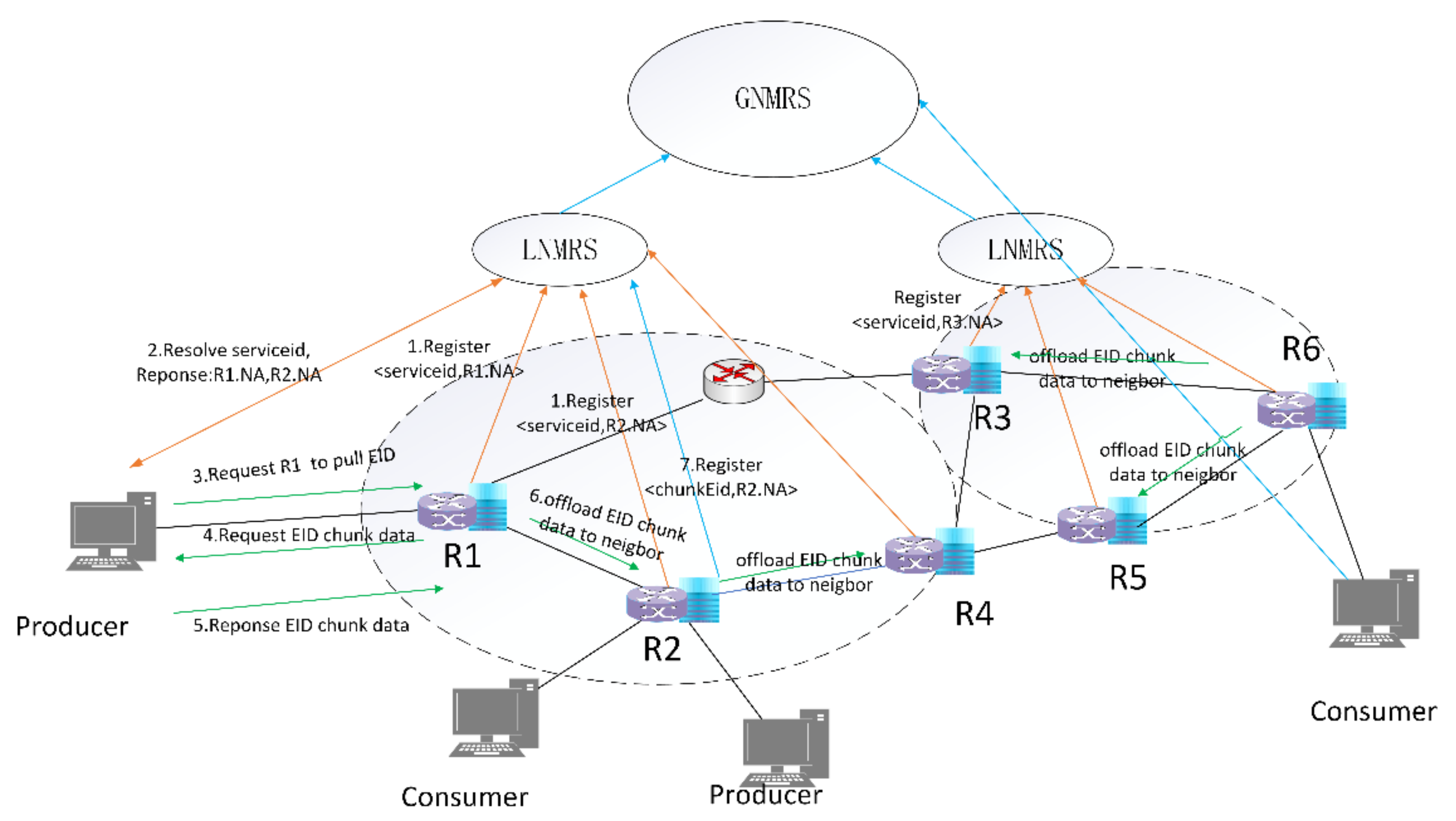
  • An intermediate node with storage service capability, which has been deployed in the network, registers a mapping of a specific identifier indicating a storage service and its Network Address (NA) (selecting any one of the interface IP addresses as the node’s NA) with the LNMRS (step1). As shown in Figure 1, there are two local resolution areas marked with a dashed circle.
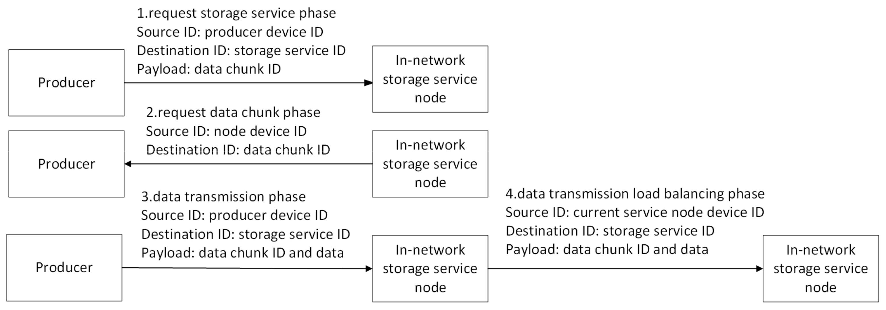
  • Pull-based communications offer several advantages over push-based communications, such as built-in multicast delivery, receiver-oriented congestion control, and native support for client mobility [28]. To support proactive in-network storage, the producer initiates the sending of a “request for pull” message to a storage service node instance, which, in turn, triggers a pull request to be sent back to the producer by the instance. When the producer requests the in-network storage services, the producer first resolves the specific storage service identifier from the LNMRS to obtain the IP address list of storage service nodes (step2), which contains nearby nodes, such as R1 and R2. Then, the closest node (R1) is selected as the target according to latency, and the target (R1) is messaged to ask for the storage service (step3). The message includes the IDs of written data.
  • After receiving the “request for pull” messages, the selected node parses the IDs from the messages and requests data chunks based on the IDs from the producer (step4).
  • Then, the producer starts to send chunk data to the storage service node based on an ID-based protocol described in detail below (step5).
  • Then, the extended cooperative storage schema begins to play a role. Based on the obtained information, the decision state of the current storage service node and the corresponding neighbor information are calculated. After the storage service node receives the data chunk, the storage service node first closes the context of the corresponding ID request, and decides to forward the data chunk to local storage or its neighbor storage node. If the storage service node decides to store in a neighbor node (R2), it selects the neighbor, modifies the destination address field in the packet, and then forwards the chunk data based on the destination address (step6). Otherwise, if the storage service node decides to store locally, it directly forwards the chunk data packets to the local storage module for chunk data storage.
  • The selected neighbor node receives the chunk data and stores it locally. After chunk data is stored in the storage service node, the mapping of the ID of the data chunk and the NA of the storage service node is registered to LNMRS for further retrieval (step7).
  • If there are no available neighbor nodes and the current node has no capability to deal with the data chunk packets, it will forward the packets to the least loaded neighbor and subtract 1 from the TTL field, which indicates the longest storage node path it can forward along. It is currently considered that the chunk data can only be offloaded once; thereafter, there is a need to wait for the data to be stored locally or forwarded to a unified flood discharge area in the cloud. The storage service nodes are assumed to have been deployed ahead of time, which is outside the scope of this paper.
  • Similar processes can be executed in another local resolution area. It is assumed that traffic offloading is not possible between different resolution domains. Every storage service node can execute the offload process mentioned above in its own local resolution area, so that the entire network iteratively achieves load balancing.
  • Then, the consumer queries the GNMRS or LNMRS for the data chunk ID, obtains the NA of R2, and obtains chunk data from R2.

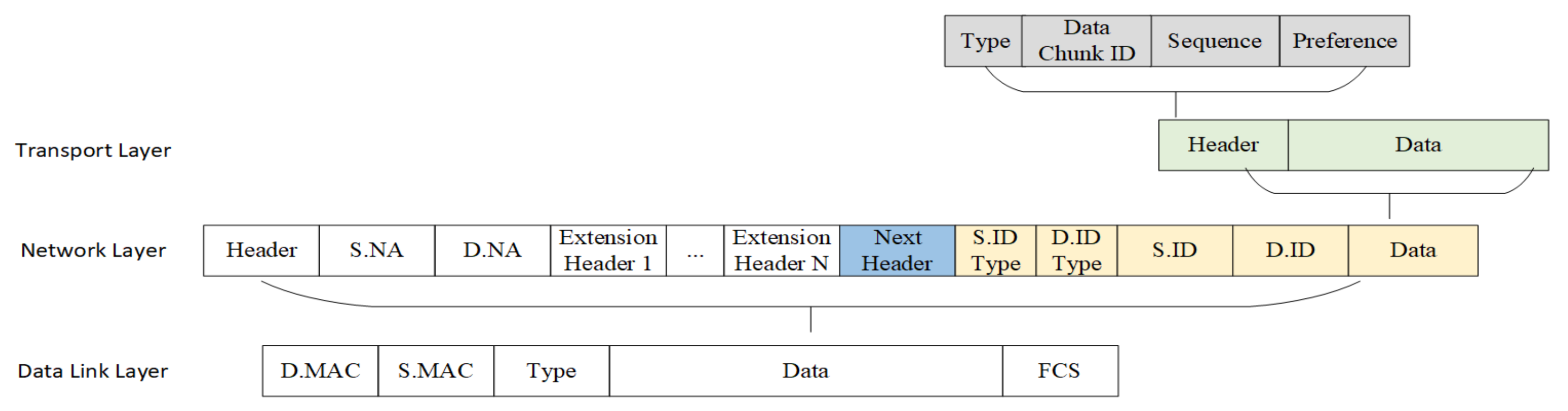
3.2. An ID-Based Cooperative Storage Protocol

An identifier is a series of digits, characters, and symbols or any other form of data used to identify subscribers, users, network elements, functions, network entities providing services/applications, or other entities [29]. Entities are named using a persistent name, which does not change with mobility. This name may also be used by the network to locate, replicate, cache, and access the data. Due to the use of non-semantic identifiers as data names, other attributes of data, including signatures, life cycles, and preferences, can be maintained by the application, and the relationship between the attributes and the ID can also be maintained at the application layer.
In ICN, the data is a first-class citizen. To facilitate data transmission, caching, and storage, the data must be named by an identifier. Many methods can be used to assign the name to a data chunk [29], such as the hierarchically human-readable naming method, the self-certifying flat naming method, the attribute-based naming method, and the hybrid method of the multiple naming mechanism. In this paper, the name is composed by the hash value of the URI and the hash value of the data chunk. To process IDs more efficiently in the network, identifier-related fields are added into the packet header when the packet formats are designed. By also referring to the ID length in MobilityFirst [30], we choose the same length as that of the MobilityFirst GUID, which has a length of 20 bytes. The concept of an end-to-end connection does not apply in ICN, which has multisource routing, so our proposed transport protocol is connectionless [26]. In addition, due to some defects of IPv4, our proposal is designed to expand the next header field based on the IPv6 protocol. We name the proposed schema the identifier protocol (IDP), where a set of rules and regulations that specifies how the locators of a data packet are manipulated based on the ID in the network layer under the ID/locator separation of ICN.
Figure 2 shows the IDP protocol layer layout, which is based on the current TCP/IP protocol (IPv6), including mainly the network layer and transport layer. In the network layer, an ID header acts as the last header using the extension header defined in IPv6 [31]. The ID header contains the Next Header field, the Source ID type field, the Destination ID type, the Source ID field, and the Destination ID field. Because the intermediate router, who cannot recognize the ID header, will ignore the unsupported extension headers, the use of an extension header in IPv6 to host the ID is compatible with existing TCP/IP architectures [25].
The “Next Header” field of the ID header is used to specify which transport protocol the packet will be passed to for processing. It can include our proposed transport protocol SEADP (Data Protocol in SEANet [32]), and can also point to an existing transport layer, such as TCP or UDP. We select 0 × 99 as our transport protocol value from the unsigned range 144–252 in the IANA registry ipv6-parameters [25].
Because various entities in the network can be labelled an identifier (including data and services), it may be necessary to classify IDs. We designed two fields to respectively identify the source ID type and the destination ID type.
For in-network data storage service, there are at least two types of packets, namely storage service request packet and data chunk request/response packet. We mainly combine source device ID and storage service ID, and source device ID and data chunk ID, to deal with in-network data storage service. The main ID combination relationship is shown in Figure 3. First, the producer requests the storage service through the producer’s device ID as the source ID, the storage service ID as the destination ID, and the data chunk ID contained in the transport layer header. The storage service node requests the data chunk through the storage service node’s device ID as the source ID and the data chunk ID as the destination ID. Then, the producer sends the data packet with the producer’s device ID as the source ID, the storage service ID as the destination ID, and the data chunk ID and data contained in the payload. If the storage service node offloads the packets, the packets’ destination IP is modified and the ID fields are unchanged, and are then forwarded.
All IPv6-compliant hosts should be able to dynamically determine the packet length to be transmitted, for example, by using the path MTU discovery process. Briefly, when a host sends a very large IPv6 packet, the router does not segment the packet if it cannot forward such a large packet, but returns an error message to the sending host. This message tells the host that all future packets sent to the destination address will be segmented. It is far more efficient for hosts to send packets of the right size in the first place than for routers along the way to dynamically fragment each packet. Because IPv6 is an end-to-end transmission protocol and the concept of an end-to-end connection does not apply in ICN, our proposed transport protocol is connectionless. There is no handshake throughout the transmission, thus reducing the latency associated with establishing the connection [25]. Considering the optimal chunk size for efficient transmission in ICN and the large overhead that a small data chunk imposes on transmission and caching [33], the data chunk size is set to several MBs in our proposal. The designated data chunk size is larger than that of the path MTU, so the data chunk needs to be segmented. The segmentation information, including data chunk ID and the segment number, remains in the data chunk transport layer header. In addition, a new field, “preference”, was designed, and is mapped from application-related requirements, including storage QoS, specific storing positions, caching strategies, security strategies, multipath transmission, and one-to-many transmission based on multicasting. The intermediate node may execute the corresponding action according to the “preference” field. Our proposed transport protocol SEADP header mainly contains “type”, “data chunk ID”, “sequence”, and “preference” fields. The “type” field currently contains the data request packet and the data chunk response packet. The “data chunk ID” field represents the identifier of the data to be transmitted and stored. The “sequence” field of the packet indicates the segment number of the data chunk segmented by data source.

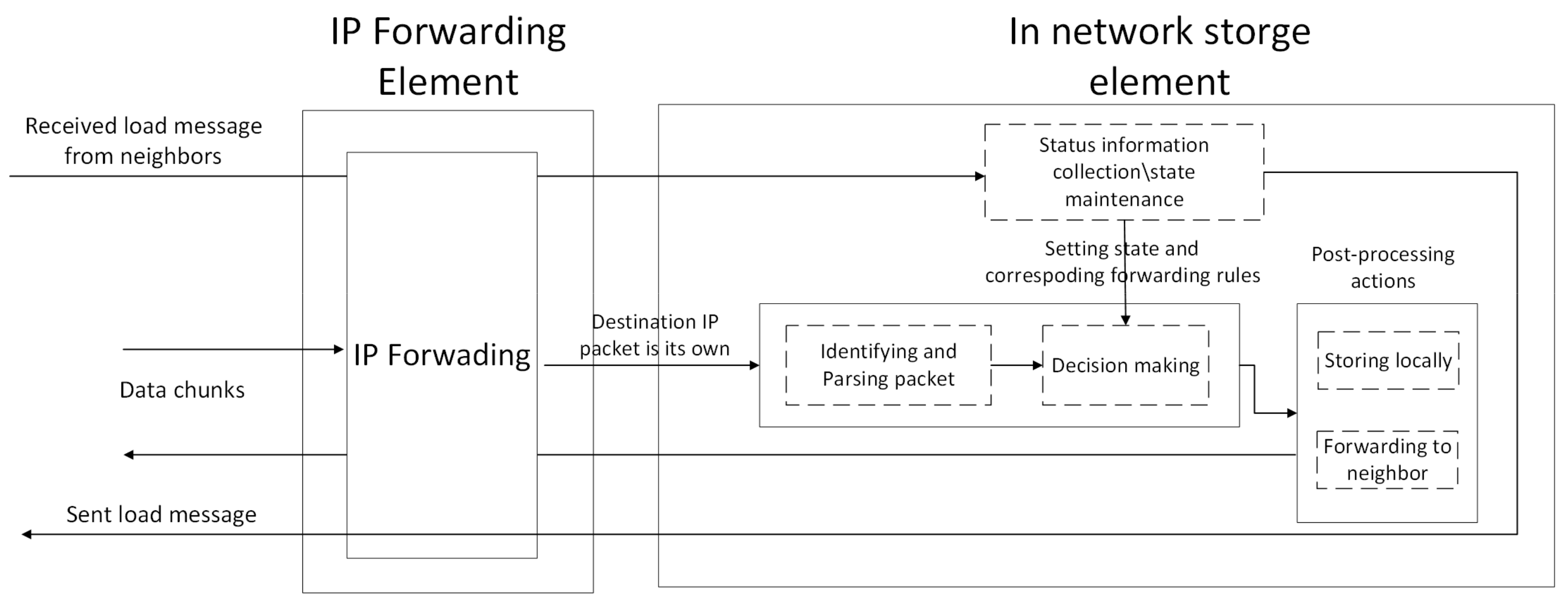
3.3. In-Network Storage Service Node Structure

According to the ID-based protocol described in Section 3.2, the intermediate router’s in-network storage function is enhanced to take advantage of the power of the ID to support in-network storage. We designed its structure based on a programmable data plane. Figure 4 shows the inner structure of the enhanced network node. This can be an instance of a local computing model in ICN based on control and user plane separation. Currently the node structure is assumed to be deployed on every network node. The deployment is outside the scope of our paper and will be studied in other articles.
The network intermediate nodes first need to ensure line-speed forwarding. In order not to affect the forwarding performance of the network intermediate nodes, the relevant status information collection, calculation, and maintenance are placed in the network storage processing element using local computing capacity. In addition, the calculated state value and decision result are inserted into the forwarding processing pipeline for ID-based protocol processing through the programming interface. The structure includes: the Identifying and Parsing packet, Decision making, Post-processing action, and Status information collection/state maintenance.
  • The “Identifying and Parsing packet” module needs to correctly identify our ID-based transport layer packet, parse packet fields, and obtain the storage service ID/data chunk ID, sequence, and preference;
  • The “Decision making” module executes one of the “post-processing actions” according to the state sets. If the state is set to “forwarding to neighbor node”, the “Decision making” module executes the “Forwarding to neighbor” action; otherwise, the “Storing locally” action is invoked;
  • The “Post-processing actions” module currently contains “Storing locally” and “Forwarding to neighbor”. The “Forwarding to neighbor” action will change the destination IP of the data chunk packet to a new destination according to the rules from the computation result of the “Status information collection/state maintenance” module and then forward it. The “Storing locally” action will ACK the received packet, and then request the next segment and reassemble the data chunk from segments for storage in the local file system;
  • The core module is “Status information collection/state maintenance”. This module periodically collects neighbor status information and local status information, and parses packet information, then computes the state threshold and maps forwarding rules based on the ID. These results are set to shared memory that the forwarding pipeline can access according to the programmable interface. The time interval should be set at least as high as the maximum average RTT in the network [34].

4. In-Network Cooperative Storage Mechanism

4.1. Neighbor Selection Mechanism

LNMRS is usually deployed at the edge of the network and close to the forwarding devices, and maintains local ID–locator pairs. As a result, LNMRS may be more efficient or provide on-site service for users. LNMRS is also a hierarchical service system with a distributed architecture, which can synchronize part of the mapping of the ID and NA to GNMRS to be accessed globally [35].
The in-network storage service node registers the mapping storage service ID and its NA to LNMRS on startup. Considering the locality of the storage and a fast response, the neighbor nodes should be selected from nearby nodes. In addition, LNMRS is a suitable choice to select candidate neighbors by resolving the service ID.
In the case of the storage, congestion occurs where the transmission bandwidth is limited or storage IO is insufficient. Only considering link bandwidth or node storage capability is not enough, especially in high throughput traffic scenarios. Thus, we combine the two pieces of information as the criteria for node selection. The load information exchange packet contains the current input interface’s total available input and output bandwidth (interface_total_bandwidth), and the current node’s available writing throughput (wIO) and message identification. When the neighbor node receives a load information exchange packet, it will respond with an ACK. Based on the received ACK time, we estimate the latency (RTT). RTT is computed as an exponentially weighted moving average (EWMA) of RTT in Equation (1). r t t i is the time from the transmission of the i-th packet until receipt of the ACK of the i-th packet. R T T i is estimated as the average round trip time after the i-th packet. We assume RTT0 = 0 and α = 0.125 (which is a typical value in TCP [36]).
R T T k i =   1 α     R T T k i 1 +   α     r t t k i
The neighbor node’s weight is computed based on the neighbor’s interface_total_bandwidth and available writing throughput in Equation (2).
neighbor weight k = β     b a n d w i d t h k     R T T k   +   1 β     w k I O R T T k / 2
The weight of the node itself is computed in Equation (3) based on the node’s available writing throughput and the average RTT of all neighbor nodes.
self _ weight = w I O a v e r a g _ R T T / 2
Because the chunk data needs to be shifted from nodes with heavy load to those with less load, determining when to shift the load is important. We define a normalized value γ in Equation (4).
γ = s e l f _ w e i g h t i min ( w e i g h t k , k n e i g h b o r s _ l i s t | i ) m a x w e i g h t k , k n e i g h b o r | i min ( w e i g h t k , k n e i g h b o r s _ l i s t | i )
If γ is smaller than the defined threshold, the chunk data should be offloaded to its neighbors; otherwise, the traffic is not offloaded to its neighbors and it is better to store the chunk itself. We defined the threshold as 0.5 in simulation. When the threshold is set to 0, it means it has no cooperative storage mechanism and is just like a common node.
As shown in Algorithm 1, when the node is in the cooperative state, it sorts the neighbors’ weight and selects a certain number of nodes (N) that exceed the current node’s weight value as its final offloaded targets. Then, the traffic is split by the data chunk ID to these selected targets according to their weights.
Algorithm 1 Neighbor selection algorithm.
Input:
rtt = r t t 1 i , r t t 2 i , r t t k i , current rtt of each neighbor interface;
b a n d w i d t h =   b a n d w i d t h 1 i , b a n d w i d t h 2 i , b a n d w i d t h k i , current bandwidth of each neighbor interface;
w I O = w I O 1 i , w I O 2 i , w I O k i , , current writing throughput of each neighbor;
Output: state, target_list
1: Initialize RTT0 = 0, α = 0.875,   β = 0.1
2: While k < K do
3: calculate RTT(k) ← Equation (1)
4: calculate neighbor_weight(k) ← Equation (2)
5: EndWhile
6: calculate averag _ RTT = 1 K 1 K R T T k
7: calculate self_weight ← Equation (3)
8: calculate normalized value γ ← Equation (4)
9: if  γ < t h r e s h o l d , then
10:  state ← “cooperative”
11:  sortedlist ← sort (neighbor_list|i) by weight desc
12:  sublist ← subsist (0, number_threshold-1) from sortedlist
13:  target_list ← sublist
14: else
15:  state ← “local_storage”
16: EndIf
17: Return state, target_list

4.2. Cooperative Storage Strategy

Many load-balancing strategies have been proposed in academia and industry, such as the round robin strategy, random strategy, hash strategy, or weight-based strategy [37], and traffic splitting in programmable switches [38,39,40,41]. The round robin strategy distributes traffic equally among the instances by forwarding traffic to each instance in turn. The random strategy will select a random instance to forward traffic. The hash strategy will compute the hash value x of a field, such as the source IP or destination IP, compute index y as × mod K (the count of instances), then obtain the corresponding target based on y in K targets. Traffic splitting in programmable switches mainly focuses on the weight approximation using flow table entries, but is still subject to flow-based traffic and does not consider how to obtain the weight. The strategies above do not consider the weight of targets and will cause load unbalancing if flow-based splitting is used. We consider the weight-based strategy and compute the relative weight in Equation (5).
relativeWeight n = w e i g h t n 1 N w e i g h t n
According to the relative weight ratio of K nodes, we calculate the number of nodes corresponding to the constraint of storage space having a length under M (each index occupies 2 bytes) in Equation (6).
Count n   = f l o o r   r e l a t i v e W e i g h t n     M   / 2
Then, two linear storage spaces are constructed separately for storing the index of targets and targets’ IPs. Linear Storage Space 1 is used to store the index of the neighbors’ IP, which is stored in Linear Storage Space 2. The flow entries will match the L bits of the ID’s suffix; then, the actions are executed to determine whether it is in the cooperative state. If this is the case, the corresponding index x is searched for in Linear Storage Space 1 based on the value of the L bits of the ID’s suffix; the target IP in Linear Storage Space 2 is obtained with the value of index x as the index in Linear Storage Space 2; and the “Forwarding to neighbor” action is executed. Figure 5 shows a simple example.
However, the ping-pong loops problem may exist. When a producer P1 begins to store chunks, the corresponding in-network storage service node A enters the load balancing state, and may offload a portion of the chunks to its neighbor B according the load balancing rules. Immediately afterwards, the in-network storage service B receives the data storage from another producer P2. Assuming that A is also a neighbor of B, B also enters the cooperative state after calculating the normalized value of its weight. A portion of the chunks may be offloaded to A according the offloading rules in B. After A receives these chunks, they may be offloaded to B according to A’s offloading rules, and a loop occurs. To avoid ping-pong loop problems, the input port avoidance mechanism is adopted. The input port avoidance mechanism is used to exclude the input port of the packet and to prevent forwarding to the input port where the packet comes. It is currently considered that the chunk data can only be offloaded once, before waiting to be stored locally or forwarded to a unified flood discharge area in the cloud. The detailed algorithm is described in Algorithm 2.
Algorithm 2 Cooperative storage algorithm.
Input:
weight =   w e i g h t 1 , w e i g h t 2 , , w e i g h t n , node weight of selected targets;
Output:
1: Initialize
2: While n < N do
3:  calculate relativeWeight n ← Equation (5)
4:  calculate Count n ← Equation (6)
5: EndWhile
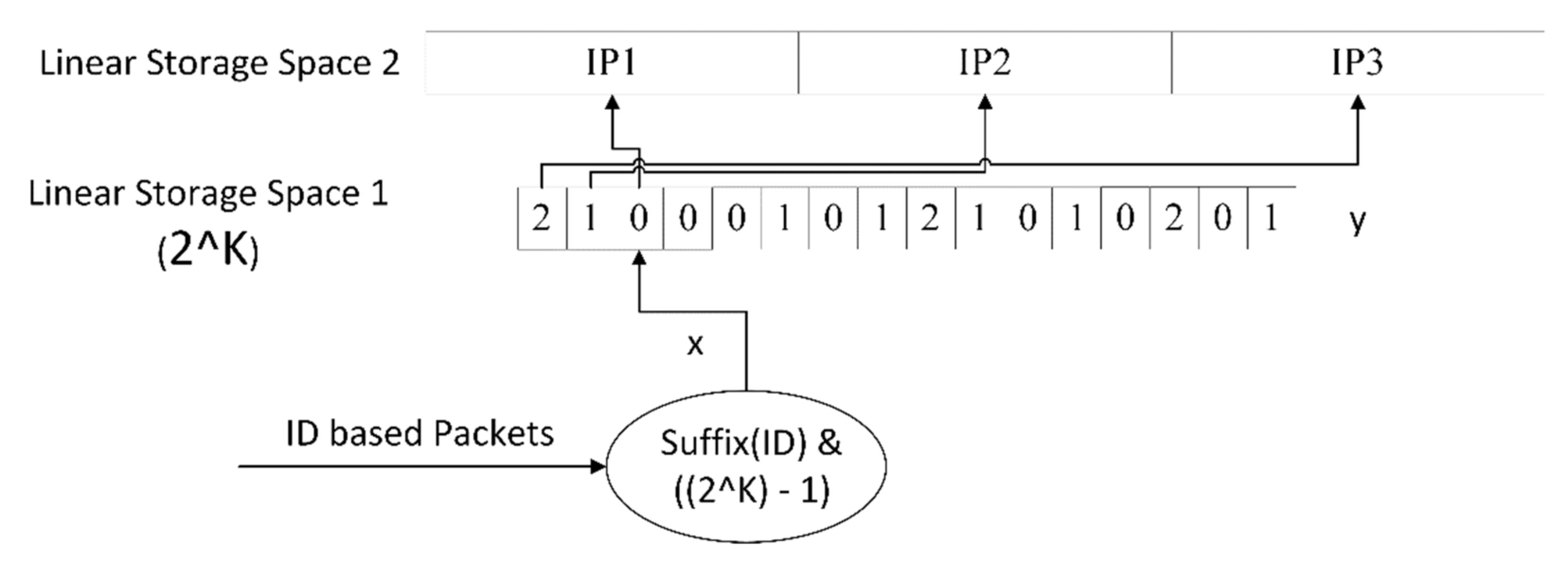
6: fill up linear storage space 1
7: fill up linear storage space 2
8: calculate index1=hash(ID) % N
9: get index2 = linear_storage_space_1(index1)
10: get destination = linear_storage_space2(index2)
11: get Out_port from destination
12: if packet.In_port == Out_port, then
13:   Local Storage
14: else
15:   Forward to neighbor
16: Return

5. Evaluation

The rationality and performance of the algorithm were verified and evaluated using an actual deployed prototype system in a simulation environment for a large-scale scientific facility.

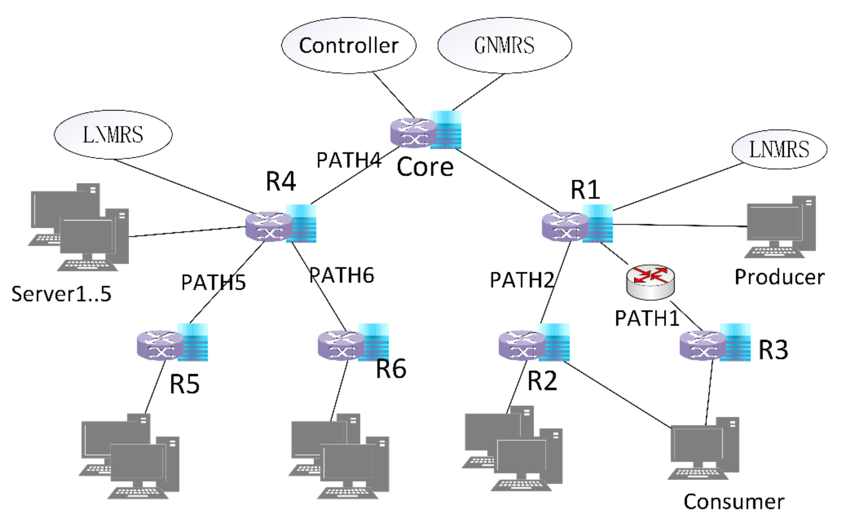
5.1. Network Environment Setup

The network topology is a simple FatTree topology, as shown in Figure 6. All the switches, except a common layer 3 Huawei router between R1 and R3, are our own programmable switches implemented based on a Protocol Oblivious Forwarding (POF) switch [42]. The controller is implemented based on an ONOS controller. We implemented the whole routing process based on the POF protocol and corresponding instruction sets. These applications can support hybrid routing with the current IP infrastructure through OSPF.
The key components are GNMRS and, in particular, LNMRS. We implemented LNMRS, which can maintain name and NA mapping for resolving the ID to addresses locally, and synchronize a portion of the mappings of the ID and NA to GNMRS to be accessed globally.
In the network topology, our in-network storage modules are deployed in every POF switch, which are connected with 10 Gbps optical fiber. In addition, there is a common layer-3 IP router in the path from R1 to R3. This can simulate the hybrid network environment, and is also used for traffic control, because our new protocol is implemented based on the raw socket in a Linux environment and the network throughput in the Linux server can only achieve 4 Gbps on average. Two servers, namely the producer and the consumer, are connected to the network using 10 Gbps optical fiber. All POF switches are configured for in-network storage with a size of 10 TB.

5.2. Performance Results

We mainly focus on the throughput and transfer time influenced by the load balancing schema in the ID-based data chunk transmission.

5.2.1. Evaluation of the Selection Mechanism

To evaluate our neighbor selection mechanism, we use the left part of the topology to compare our proposal with the ECMP mechanism under a constructed flow. We use three servers to simulate two 4 Gbps data flows and one 2 Gbps data flow. We limit the bandwidth between R4 and R5, and the bandwidth between R4 and R6, to 4 Gbps. In addition, the bandwidth between R4 and the core is limited to 2 Gbps. According to the ECMP mechanism, the paths R4 → R5, and R4 → R6 are equal cost paths.
First, server one writes 4 Gbps data flows to R4 for 30 s. After 10 s, server two writes 4 Gbps data flows to R4 for 30 s. Then, server three writes 2 Gbps data flows to R4 for 30 s. We compared our proposed neighbor selection mechanism with ECMP and compared statistics for the throughput of the two mechanisms. Figure 7 shows the throughput of our selection mechanism and ECMP. The data flow generated by our mechanism is basically consistent with the expected data flow. However, the ECMP mechanism cannot achieve the expected data flow and has a long flow completion time. Our peak data traffic reached 10.43 Gbps and ECMP’s peak data traffic was only 7.51 Gbps. In addition, during the period of 20 to 30 s of the whole experiment, the ECMP mechanism could not use more paths to offload the excess traffic. The network started to become congested, resulting in a drop in throughput. According to the ECMP mechanism, two paths can only be used for storing data and the peak throughput absorbed by R4 is about 8 Gbps. Our neighbor selection mechanism can discover three paths and split the data traffic, thereby improving the flow completion time.

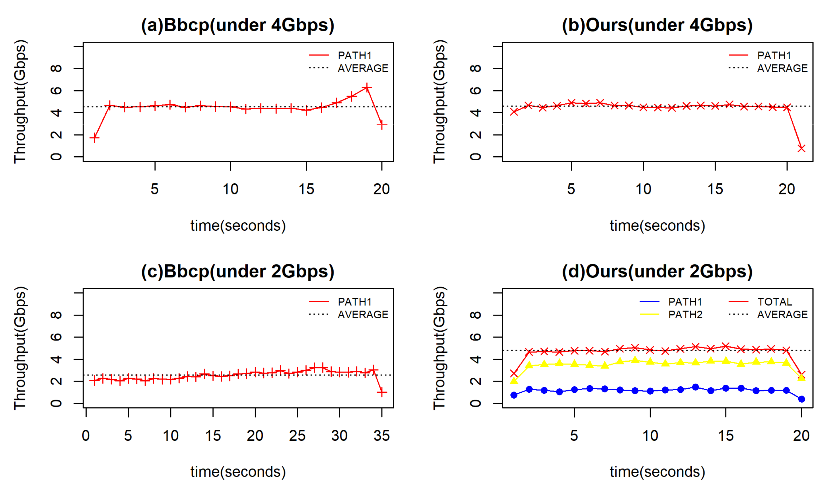
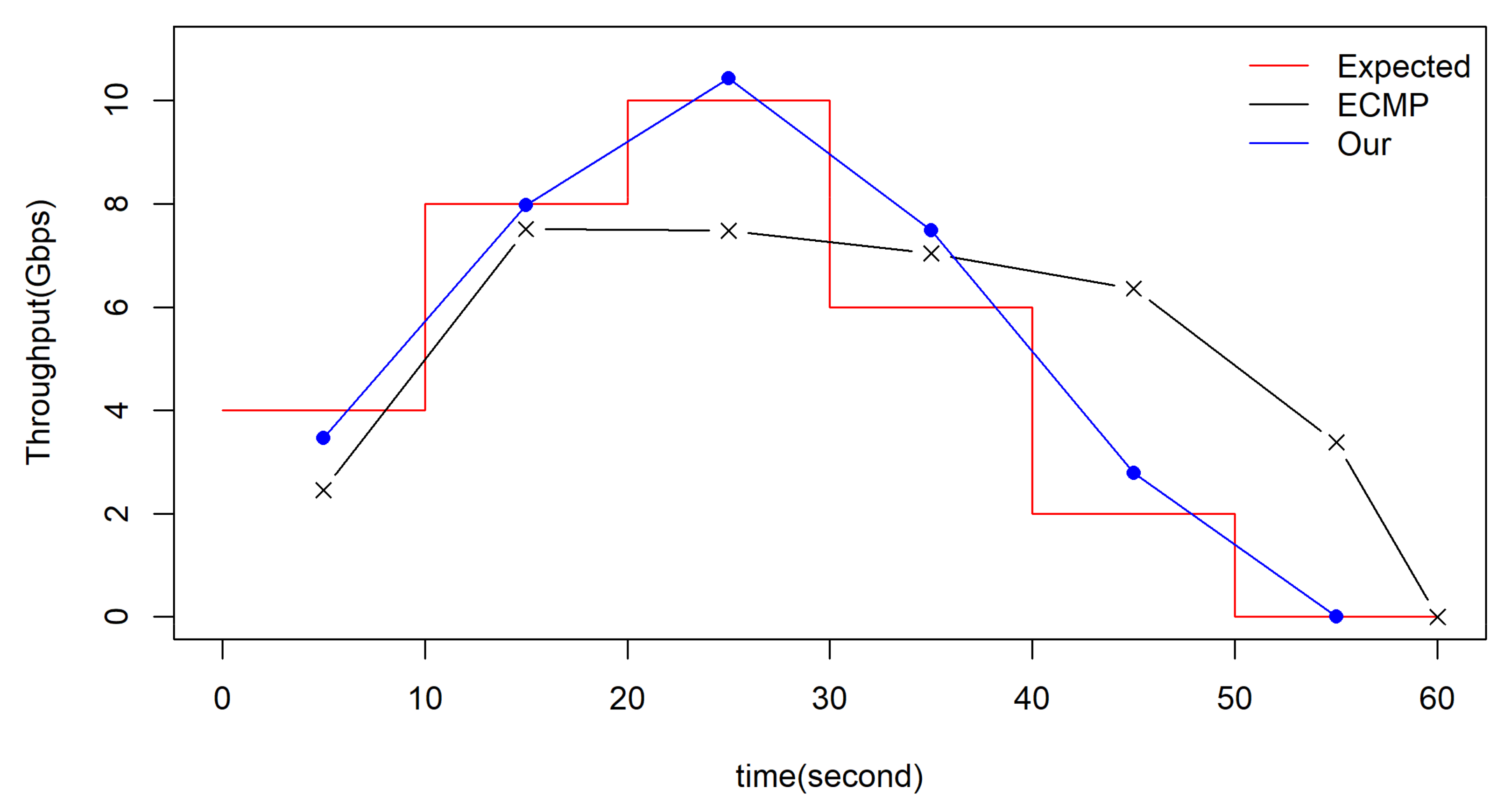
5.2.2. Comparison with End-to-End Transmission

Bbcp [43] is a point-to-point network file copy application, which is capable of transferring files approaching line speeds in a wide area network (WAN). We tested this under our simulated network environment and found that it can almost occupy the whole bandwidth when the link is idle. However, it can use the single shortest path and has no awareness of multipath. Our in-network storage can discover multiple neighbors to offload its traffic based on the LNRMS. If there is congestion in the shortest path, the efficiency of Bbcp is degraded. However, our in-network storage is barely influenced because of its selection of multiple neighbors and the traffic splitting mechanism.
To evaluate the end-to-end transmission and in-network storage, we carried out four experiments, including an end-to-end remote file transfer test and an in-network storage test under no constraint on the bandwidth, and an end-to-end remote file transfer test and an in-network storage test under a network bandwidth constraint. We used the right-hand part of the topology in Figure 6. The bandwidth from the producer to the consumer was 10 Gbps in the physical link and the network throughput of our current transport layer protocol stack implemented in the raw socket only reached 4 Gbps on average. Therefore, to ensure a fair evaluation between the end-to-end transmission and in-network storage, we limited the bandwidth of the link between R1 and R3 to 4 Gbps.
First, we constrained the bandwidth between R1 and R3 to 4 Gbps. In Figure 8a, the transmission bandwidth of Bbcp is shown between the producer and the consumer along the path of producer → R1 → R3 → consumer under the constraint of 4 Gbps controlled by the common router in the path of R1 to R3. It shows that the average bandwidth of Bbcp is 4.53 Gbps and Bbcp almost uses all the available bandwidth. From Figure 8b, the average transmission bandwidth of our proposed algorithm is 4.6 Gbps when our proposed algorithm is not in a cooperative state, and it only stores the data in R1. The bandwidth utilization of our algorithm is almost the same as that of Bbcp. The file transfer time is compared in Table 1.
Then, the bandwidth between R1 and R3 was limited to 2 Gbps. In Figure 8c, the average transmission bandwidth of Bbcp is only 2.56 Gbps because it can only use the single path of producer → R1 → R3 → consumer. It can also be seen in Figure 8d that the average transmission bandwidth of our proposed algorithm is 4.82 Gbps, which is barely influenced by the constraint, because the proposed algorithm can use R2 to cooperatively store its data and the bandwidth from R1 to R2 is 10 Gbps [44]. In all our tests, we transferred the same file having a size of 10 GB. In addition, the transfer time of Bbcp was also lengthened due to bandwidth rate degradation. The transfer time of our proposed algorithm showed almost no increase although there was a slight truncation of the traffic.
From the comparison, we can see that our proposed algorithm is useful in improving the bandwidth usage, especially in multiple path environments.

5.2.3. Influence of Cooperative Storage Schema

Traffic is spilt based on the flow or flowlet in common load-balancing strategies. The flow-based load balancing strategies must distinguish between elephant and mice flows, because these two flows have an obvious influence on the load-balancing strategies. If the traffic is split based on an elephant flow, it may overload the target while the other servers are underloaded. Conversely, if the traffic is a mice flow, it may be not beneficial to split it over multiple servers due to the cost of packet reordering. Our proposed cooperative storage schema is based on the splitting of the data chunk by the application, which can be stored in a disordered state between data chunks and in different locations. The only requirement is that the packets in a chunk are delivered in order. This can be realized using an in-network cache to temporarily hold complete chunks in hop-by-hop transmission [45], or by utilizing the suffix of the ID to match flow entries to maintain the consistency of the packet forwarding path. We used the second method to implement our schema considering the latency of the hop-by-hop transmission.
To verify our cooperative storage strategy, we evaluated our algorithm and the ECMP algorithm under equal weights and under changed weights. We varied the weights by changing the network bandwidth between R1 and R3.
We undertook the experiments using two split ratios under our network environment with no bandwidth constraint. First, we used R1 to split data chunks equally to R3 and R2, and gathered statistics of bandwidth usage and transfer time. Figure 9a shows 4.77 Gbps on average was achieved where there is no cooperative storage strategy. Second, we limited the bandwidth of the path from R1 to R3 to 1 Gbps, and the split ratio of PATH2 to PATH1 was changed to 3:1. From Figure 9c, we can see that we obtained total bandwidth of 4.69 Gbps, which is comparable to the bandwidth of 4.77 Gbps in Figure 9a. Furthermore, the transfer time in the two cases is nearly the same from Table 2. Our cooperative storage strategy has no influence on transmission bandwidth because of the chunk ID-based transmission.
Then, we limited the bandwidth of PATH1 to 1 Gbps and undertook the experiments to load balance the traffic between PATH1 and PATH2. The actual transmission bandwidth was reduced to 3.0 Gbps, compared with 4.77 Gbps under no constraint in Figure 9b. The incorrect split ratio causes congestion on PATH1, degrades the transmission speed of PATH1, can resulting in a decrease in the total bandwidth. The transfer time of ECMP under the split ratio of 1:3 was increased to 28.5 s, compared to the transfer time of 17.6 s of our schema in a split ratio of 1:3. The congestion and fluctuation of traffic in PATH1 result in heavy partial packet transmission, and the transfer time is even more significantly affected from Table 2. Thus, our weight-based schema is more efficient than the schema without an awareness of the multipath state.

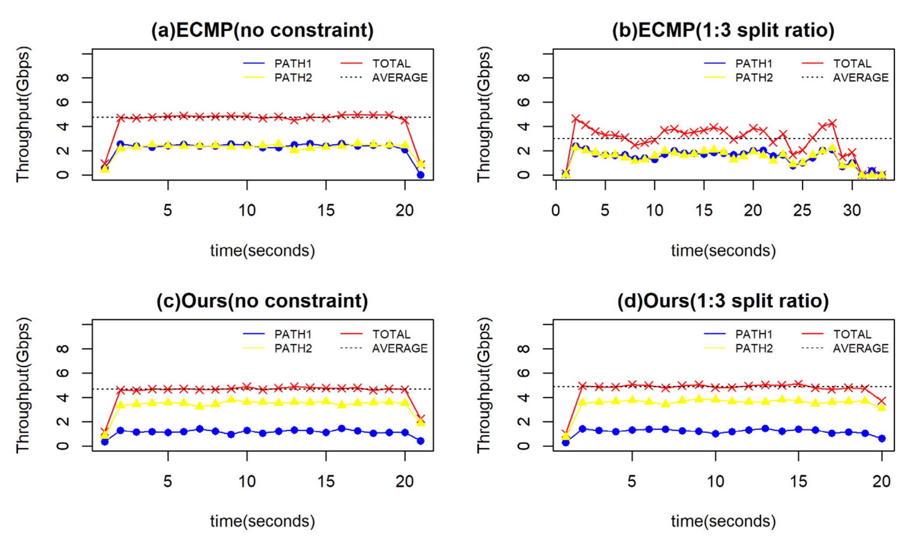
5.2.4. The Accuracy of Traffic Split Ratio

Given a limited rule capacity at the switch, we need to make a tradeoff between the accuracy of the traffic split ratio and the number of flow entries. We measured the throughput under different lengths of the ID’s suffix (M) under an expected split ratio of 4:1. We adjusted the bandwidth ratio between PATH1 and PATH2 to 1:4 through the three-layer router.
When the length of the matched ID’s suffix is 2, we built four flow entries for every interface. The mask of the corresponding field is 0 × 11, and the IDs are split in the ratio of 3:1. If the length of the matched ID’s suffix is 3, the IDs are split in the ratio of 3:1, and the IDs are split in the ratio of 4.3:1 when the length of the matched ID’s suffix is 4. As shown in Figure 10, the measured traffic ratio (4.4:1) is the most accurate when the length of the ID’s suffix is 4. However, the number of flow entries is also the greatest. If the split ratio needs to be updated frequently, the cost of maintaining the accuracy of the traffic split ratio and the resulting traffic fluctuation cannot be neglected.

5.2.5. Comparison with Common File Systems

We compared our in-network cooperative storage system with IPFS and CEPH, which are common distributed storage systems. We wrote different files having sizes of 1, 5 and 10 GB to these file systems under different cluster sizes (including three and five nodes). Our experiments show that the average throughput of the three-node CEPH cluster is about 8 Gbps. When the number of CEPH cluster nodes increases to five, the average throughput is about 9.15 Gbps for a single client. The average throughput of the five-node CEPH cluster drops to about 8.05 Gbps when two clients write simultaneously. It is shown that CEPH achieved a relatively high performance through load-balancing strategies. However, this is still implemented in the application layer based on the current IP infrastructure. CEPH has inherent flaws, such as application layer protocol processing and scheduling overhead. IPFS is another popular distributed storage system based on DHT. It takes about 2 min to upload a 10 GB file for the first time, but the time for subsequent uploads is reduced by half. The average upload rate is about 1.5 Gbps in IPFS.
We used five servers to write simultaneously to R4, and the bandwidth of PATH4 was limited to 2 Gbps. The traffic of the R4 output interface is shown in Figure 11. Four servers can write at an average of 4 Gbps, whereas one server can write at only 1.6 Gbps. The peak throughput reaches 16.3 Gbps when five servers write simultaneously, and the average throughput is about 9.3 Gbps. Through experiments, it is shown that our storage system co-designed with the network is more suitable for real-time data writing. By comparison, IPFS is more suitable for file sharing, and CEPH is a cluster system, which is limited by its scale.

6. Conclusions

This paper proposes an in-network cooperative storage schema based on neighbor offloading, in which the ID-based traffic is sequentially dynamically offloaded to neighbors and multiple neighbor nodes are utilized to detour the congestion path. First, we proposed an in-network storage service node structure to support cooperative storage in neighbor nodes, and designed an ID-based cooperative storage protocol. Then, a neighbor selection mechanism based on LNRMS was introduced in which the node weights are computed by combining the link bandwidth and node storage capability, and determining whether to split the traffic by comparing normalized weight values with a threshold. In addition, a cooperative storage strategy in a programmable data plane is presented using the relative weights and ID suffix matching to approximate the traffic split ratio. Finally, the experimental results show that our proposed schema is more efficient compared with end-to-end transmission and ECMP in terms of transfer bandwidth and transfer time. In the future, we will study the influence of fluctuation caused by dynamic updating due to load changes in traffic splitting under different traffic characteristics, and consider recording historical neighbor forwarding information in the versions.

Author Contributions

Conceptualization, S.D., and R.H.; methodology, S.D., and R.H.; software, S.D.; writing—original draft preparation, S.D.; writing—review and editing, R.H.; supervision, R.H.; project administration, R.H.; funding acquisition, R.H. All authors have read and agreed to the published version of the manuscript.

Funding

This work was funded by Strategic Leadership Project of Chinese Academy of Sciences: SEANET Technology Standardization Research System Development (Project No. XDC02070100).

Data Availability Statement

Not Applicable, the study does not report any data.

Acknowledgments

We would like to express our gratitude to J.W. and R.H. for their meaningful support for this work.

Conflicts of Interest

The authors declare no conflict of interest.

References

  1. Ping, H. An Overview of SHINE Data System. Available online: https://indico.ihep.ac.cn/event/13035/contribution/4/material/slides/0.pdf (accessed on 10 December 2021).
  2. Chen, G. Challenges of big data in science researches. Chin. Sci. Bull. 2015, 60, 439–444. (In Chinese) [Google Scholar] [CrossRef]
  3. Jacobson, V.; Smetters, D.K.; Thornton, J.D.; Plass, M.F.; Briggs, N.H.; Braynard, R.L. Networking named content. In Proceedings of the 5th International Conference on Emerging Networking Experiments and Technologies, Rome, Italy, 1–4 December 2009; pp. 1–12. [Google Scholar]
  4. Zhang, L.; Alexander, A.; Jeffrey, B.; Jacobson, V.; Claffy, K.; Crowley, P.J.; Papadopoulos, C.; Wang, L.; Zhang, B. Named data networking. ACM SIGCOMM Comput. Commun. Rev. 2014, 44, 66–73. [Google Scholar] [CrossRef]
  5. Fan, C.; Shannigrahi, S.; DiBenedetto, S.; Olschanowsky, C.M.; Papadopoulos, C.; Newman, H.B. Managing scientific data with named data networking. In Proceedings of the Fifth International Workshop on Network-Aware Data Management, Austin, TX, USA, 15 November 2015; pp. 1–7. [Google Scholar]
  6. Dabin, K.; Inchan, H.; Vartika, S.; Young-Bae, K.; Huhnkuk, L. Implementation of a front-end and back-end NDN system for climate modeling application. In Proceedings of the 2015 International Conference on Information and Communication Technology Convergence (ICTC), Jeju, Korea, 28–30 October 2015; pp. 554–559. [Google Scholar]
  7. Catherine, O.; Susmit, S.; Christos, P. Supporting climate research using named data networking. In Proceedings of the IEEE 20th International Workshop on Local & Metropolitan Area Networks (LANMAN), Reno, NV, USA, 21–23 May 2014; pp. 1–6. [Google Scholar]
  8. Huhnkuk, L.; Alexander, N.; Dabin, K.; Young-Bae, K.; Susmit, S.; Christos, P. NDN Construction for Big Science: Lessons Learned from Establishing a Testbed. IEEE Netw. 2018, 32, 124–136. [Google Scholar]
  9. Susmit, S.; Chengyu, F.; Christos, P. Named Data Networking Strategies for Improving Large Scientific Data Transfers. In Proceedings of the IEEE International Conference on Communications Workshops, Kansas City, MO, USA, 20–24 May 2018; pp. 1–6. [Google Scholar]
  10. Christian, E. Analysis of an Equal-Cost Multi-Path Algorithm. Available online: https://datatracker.ietf.org/doc/html/rfc2992 (accessed on 10 December 2021).
  11. Liu, M.; Luo, L.; Nelson, J.; Ceze, L.; Krishnamurthy, A.; Atreya., K. IncBricks: Toward In-Network Computation with an In-Network Cache. In Proceedings of the Twenty-Second International Conference on Architectural Support for Programming Languages and Operating Systems, Xi’an, China, 8–12 April 2017; Volume 52, pp. 795–809. [Google Scholar]
  12. Stathis, M.; Bianca, S. The Evolution of the Hadoop Distributed File System. In Proceedings of the 2018 32nd International Conference on Advanced Information Networking and Applications Workshops (WAINA), Krakow, Poland, 16–18 May 2018; pp. 67–74. [Google Scholar]
  13. Ghemawat, S.; Gobioff, H.; Leung, S.-T. The Google File System. SIGOPS Oper. Syst. Rev. 2003, 37, 29–43. [Google Scholar] [CrossRef]
  14. Weil, S.A.; Brandt, S.A.; Miller, E.L.; Long, D.D.E.; Maltzahn, C. Ceph: A Scalable, High-Performance Distributed File System. In Proceedings of the 7th Symposium on Operating Systems Design and Implementation, Seattle, DC, USA, 6–8 November 2006; pp. 307–320. [Google Scholar]
  15. Onur, A.; Truong, K.P. On uncoordinated service placement in edge-clouds. In Proceedings of the 2017 IEEE International Conference on Cloud Computing Technology and Science (CloudCom), Hong Kong, 11–14 December 2017; pp. 41–48. [Google Scholar]
  16. Tao, O.; Zhi, Z.; Xu, C. Follow me at the edge: Mobilityaware dynamic service placement for mobile edge computing. IEEE J. Sel. Areas Commun. 2018, 36, 1–10. [Google Scholar]
  17. Carofiglio, G.; Morabito, G.; Muscariello, L.; Solis, I.; Varvello, M. From content delivery today to information centric networking. Comput. Netw. 2013, 57, 3116–3127. [Google Scholar] [CrossRef]
  18. Adrian-Cristian, N.; Spyridon, M.; Ioannis, P. Store Edge Networked Data (SEND): A Data and Performance Driven Edge Storage Framework. In Proceedings of the IEEE INFOCOM 2021-IEEE Conference on Computer Communications, Virtual Conference, 10–13 May 2021; pp. 1–10. [Google Scholar]
  19. Eve, M.; David, Z.; Jeff, S.; Moustafa, H.; Brown, A.; Ambrosin, M. An Architectural Vision for a Data-Centric IoT: Rethinking Things, Trust and Clouds. In Proceedings of the 2017 IEEE 37th International Conference on Distributed Computing Systems (ICDCS), Atlanta, GA, USA, 5–8 June 2017; pp. 1717–1728. [Google Scholar]
  20. Benet, J. IPFS—Content Addressed, Versioned, P2P File System. arXiv 2014, arXiv:1407.3561. [Google Scholar]
  21. Cinquini, L.; Crichton, D.; Mattmann, C.; Harney, J.; Shipman, G.; Wang, F.; Ananthakrishnan, R.; Miller, N.; Denvil, S.; Morgan, M.; et al. The earth system grid federation: An open infrastructure for access to distributed geospatial data. Future Gener. Comput. Syst. 2014, 36, 400–417. [Google Scholar] [CrossRef]
  22. Karl, E.; Ronald, J.; Gerald, A. An overview of cmip5 and the experiment design. Bull. Am. Meteorol. Soc. 2012, 93, 485–498. [Google Scholar]
  23. Alvise, D.; Peter, E.; Fabrizio, F.; Andrew, H. Xrootd-a highly scalable architecture for data access. WSEAS Trans. Comput. 2005, 4, 348–353. [Google Scholar]
  24. Ying, C.; Fan, L.; Edmund, Y.; Ran, L. Enhanced VIP Algorithms for Forwarding, Caching, and Congestion Control in Named Data Networks. In Proceedings of the 2016 IEEE Global Communications Conference (GLOBECOM), Washington, DC USA, 4–8 December 2016; pp. 1–7. [Google Scholar]
  25. Zeng, L.; Ni, H.; Han, R. An Incrementally Deployable IP-Compatible-Information-Centric Networking Hierarchical Cache System. Appl. Sci. 2020, 10, 6228. [Google Scholar] [CrossRef]
  26. Xu, Y.; Ni, H.; Zhu, X. An Effective Transmission Scheme Based on Early Congestion Detection for Information-Centric Network. Electronics 2021, 10, 2205. [Google Scholar] [CrossRef]
  27. You, J.; Ji, G.; Xiao, Z.; Jin, L. ITU-T Y.3075 Requirements and Capabilities of ICN Routing and Forwarding based on Control and User Plane Separation in IMT-2020. Available online: https://www.itu.int/rec/dologin_pub.asp?lang=e&id=T-REC-Y.3075-202009-I!!PDF-E&type=items (accessed on 12 December 2021).
  28. Psaras, I.; Ascigil, O.; Rene, S.; Pavlou, G.; Afanasyev, A.; Zhang, L. Mobile Data Repositories at the Edge. In Proceedings of the USENIX Workshop on Hot Topics in Edge Computing HotEdge ’18, Boston, MA, USA, 10 July 2018. [Google Scholar]
  29. Dang, S.; You, J.; Li, Y.Y. ICN-DOS, Requirements and Capabilities of Data Object Segmentation in Information Centric NETWORKING for IMT-2020. Available online: https://www.itu.int/md/T17-SG13-C-1318 (accessed on 12 December 2021).
  30. Raychaudhuri, D.; Nagaraja, K.; Venkataramani, A. MobilityFirst: A robust and trustworthy mobility-centric architecture for the future internet. ACM SIGMOBILE Mob. Comput. Commun. Rev. 2012, 16, 2–13. [Google Scholar] [CrossRef]
  31. Ye, X.; Cao, J.; Zhu, X.Y. ICN-TL Requirements and Mechanisms of Transport Layer for Information Centric Networking in IMT-2020. Available online: https://www.itu.int/md/T17-SG13-200720-TD-WP1-0589 (accessed on 12 December 2021).
  32. Wang, J.; Chen, G.; You, J.; Sun, P. SEANet: Architecture and Technologies of an On-site, Elastic, Autonomous Network. New Media 2020, 9, 1–8. [Google Scholar]
  33. Song, Y.; Ni, H.; Zhu, X. Analytical modelling of optimal chunk size for efficient transmission in information-centric network. Int. J. Innov. Comput. Inf. Control 2020, 16, 1511–1525. [Google Scholar]
  34. Schneider, K.; Zhang, B.; Mai, V.S.; Benmohamed, L. The Case for Hop-by-Hop Traffic Engineering. arXiv 2020, arXiv:2010.13198. [Google Scholar]
  35. You, J.; Zhang, J.; Li, Y.Y. ICN-NMR Framework of Locally Enhanced Name Mapping and Resolution for Information Centric Networking in IMT-2020. Available online: https://www.itu.int/md/T17-SG13-C-1319/ (accessed on 12 December 2021).
  36. Jacobson, V. Congestion avoidance and control. SIGCOMM Comput. Commun. Rev. 1988, 18, 314–329. [Google Scholar] [CrossRef]
  37. Zhou, J.; Tewari, M.; Zhu, M.; Kabbani, A.; Poutievski, L.; Singh, A.; Vahdat, A. WCMP: Weighted cost multipathing for improved fairness in data centers. EuroSys 2014, 5, 1–14. [Google Scholar]
  38. Qadir, J.; Ali, A.; Yau, K.L.; Sathiaseelan, A.; Crowcroft, J. Exploiting the Power of Multiplicity: A Holistic Survey of Network-Layer Multipath. IEEE Commun. Surv. Tutor. 2015, 17, 2176–2213. [Google Scholar] [CrossRef] [Green Version]
  39. Rottenstreich, O.; Kanizo, Y.; Kaplan, H.; Rexford, J. Accurate Traffic Splitting on SDN Switches. IEEE J. Sel. Areas Commun. 2018, 36, 2190–2201. [Google Scholar] [CrossRef]
  40. Tuncer, D.; Charalambides, M.; Clayman, S.; Pavlou, G. Flexible Traffic Splitting in OpenFlow Networks. IEEE Trans. Netw. Serv. Manag. 2016, 3, 407–420. [Google Scholar] [CrossRef] [Green Version]
  41. Kang, N.; Ghobadi, M.; Reumann, J.; Shraer, A.; Rexford, J. Efficient traffic splitting on commodity switches. In Proceedings of the 11th ACM Conference on Emerging Networking Experiments and Technologies, CoNEXT 2015, Heidelberg, Germany, 1–4 December 2015. [Google Scholar]
  42. Li, S.; Hu, D.; Fang, W.; Ma, S.; Chen, C.; Huang, H.; Zhu, Z. Protocol Oblivious Forwarding (POF): Software-Defined Networking with Enhanced Programmability. IEEE Netw. 2017, 31, 58–66. [Google Scholar] [CrossRef]
  43. Andy, H. Bbcp. Available online: https://www.slac.stanford.edu/~abh/bbcp/ (accessed on 10 December 2021).
  44. Liu, Y.; Qin, X.; Zhu, T.; Chen, X.; Wei, G. Improve MPTCP with SDN: From the perspective of resource pooling. J. Netw. Comput. Appl. 2019, 141, 73–85. [Google Scholar] [CrossRef]
  45. Klaus, S.; Bei, C.; Lotfi, B. Hop-by-Hop Multipath Routing: Choosing the Right Nexthop Set. In Proceedings of the IEEE INFOCOM 2020—IEEE Conference on Computer Communications, Virtual Conference, 6–9 July 2020; pp. 2273–2282. [Google Scholar]
Figure 1. The overview of the chunk storage process.
Futureinternet 14 00018 g001
Figure 2. IDP protocol layer layout.
Futureinternet 14 00018 g002
Figure 3. ID combination relationship in an in-network storage service scenario.
Futureinternet 14 00018 g003
Figure 4. The extended network intermediate node structure.
Futureinternet 14 00018 g004
Figure 5. The load balancing strategy procedure.
Futureinternet 14 00018 g005
Figure 6. Network topology in the evaluation.
Futureinternet 14 00018 g006
Figure 7. Results of the selection mechanism.
Futureinternet 14 00018 g007
Figure 8. Results of comparison with end-to-end transmission.
Futureinternet 14 00018 g008
Figure 9. Results of the influence of the load balancing schema.
Futureinternet 14 00018 g009
Figure 10. Results of the influence of the number of flow entries.
Futureinternet 14 00018 g010
Figure 11. Throughput when five servers write simultaneously.
Futureinternet 14 00018 g011
Table 1. Comparison of transfer time between Bbcp and our mechanism.
ExperimentsTime(s)
Bbcp (under 4 Gbps)19
Ours (under 4 Gbps)18.5
Bbcp (under 2 Gbps)33.5
Ours (under 2 Gbps)17.5
Table 2. Comparison of the transfer time between ECMP and our mechanism.
ExperimentsTime(s)
ECMP (no constraint)18
ECMP (1:3 split ratio)28.5
Ours (no constraint)18.3
Ours (1:3 split ratio)17.6
Publisher’s Note: MDPI stays neutral with regard to jurisdictional claims in published maps and institutional affiliations.

