1. Introduction
One of the main trends of ICT management nowadays is to move services once provided through physical and dedicated hardware to a virtual environment. To give some examples: firewalls, NATs, and even fully-fledged routing services quite often move from network devices landing into general-purpose hardware [
1]. In some cases a significant portion of the network is replaced by its virtual counterpart. Of course, this is not always possible for several reasons, ranging from the intrinsic limitations of general purpose hardware in managing bulks of high-frequency traffic to the reluctance of migrating to the new paradigm legacy networks, which required large investments.
Despite these contrary reasons, this tendency keeps growing fast. This depends on the reduced costs that a virtual network has in terms of deployment, scalability, and maintainability. Also, an enabling factor that makes this trend feasible is the presence on the market of cloud providers that allow to run thousands of virtual machines or containers in their clouds.
Implementing (even partially) a complex and large network architecture in terms of the virtualization paradigm requires the support of tools that can be used to transform the description of a network scenario into a distributed virtual network composed of a number of interacting entities. This implies a consistent effort of standardization and implementation.
However, the currently available platforms that allow to implement network services into a virtual environment have one or more of the following limitations (see also,
Section 2.5).
Frequently, they are vendor-specific; i.e., they are dedicated to emulating a specific hardware.
They are seldom open-source.
They usually focus only on the virtualization of specific network functions rather than allowing the virtualization of an entire network device.
They usually require platform-specific configurations. Ideally, we would like to move into the virtual environment, in just one step and on an as-is basis, both the interconnections and the device configurations (e.g., their address plans).
They seldom allow massive virtualization activities, where huge networks with hundreds or thousands of devices are virtualized.
They do not allow a seamless interconnection between the virtual environment and the physical one, based on state-of-the-art and widely adopted protocols.
We present Megalos (from the Greek word that stands for “big” or “large”). It is an open-source framework that overcomes all the above limitations and can be used to virtually implement large and complex network scenarios. Megalos has the following main features.
It supports the implementation of large and complex virtual network scenarios consisting of a number of virtual devices (VDs) where each VD may have several L2 interfaces assigned to virtual LANs.
It relies on Docker containers to run VDs that correspond to their physical counterparts, allowing the user to directly import their original configuration.
It takes advantage of an underlying distributed cluster to scale up with respect to the number of VDs that are run, leveraging Kubernetes for the management of such clusters.
It guarantees the segregation of each virtual LAN traffic from the traffic of other LANs, from the cluster traffic, and from Internet traffic, exploiting well known protocols (e.g., VXLAN and EVPN BGP).
The paper is organized as follows.
Section 2 discusses the state-of-the-art related to Megalos. In
Section 3 we model our container-based virtual network and its scalability requirements. In
Section 4 we illustrate the Megalos architecture, and in
Section 5 we focus on its networking layer.
Section 6 illustrates several use cases involving large network scenarios with thousands of VDs and LANs. In
Section 7 we experimentally show the scalability potential of Megalos by discussing the results of several experiments on a different clusters, including the measure of the overhead of the distributed environment and of its signaling protocols.
Section 8 concludes the paper with final considerations and open problems.
2. Related Work and State of the Art
In this section, we briefly survey the existing container managers and orchestrators. Second, we discuss existing emulation systems, both single-host and distributed, underlying the differences with respect to Megalos.
2.1. The Docker Container Engine
There are several container engines currently available, but Docker [
2] is the most widespread. It has been pointed out in [
3] that Docker containers have many advantages over virtual machines in data intensive applications. Especially, the overhead of Docker is negligible. The analysis in [
3] has been deepened in [
4], where Docker is compared with other container engines. In [
5], Docker-based monolith and microservice approaches to design an NFV-based system are compared and a methodology is proposed to estimate the number of instances required to maximize performance.
Due to its wide adoption, flexibility, and efficiency, we selected Docker to implement our VDs.
2.2. Orchestrators for Docker
Container engines are designed to be deployed on a single host. However, modern applications are often composed by hundred of containers that should be replicated and distributed, to satisfy some requirements like scalability and availability. To achieve these goals, container orchestrators have been developed. Briefly, their task is to distribute containers among different nodes of a cluster, following a scheduling algorithm. Also, they ensure that every user-requested container is always running, rescheduling them in case of failures.
There are currently two main open-source container orchestrators for Docker. Docker Swarm [
6] is the Docker built-in container orchestrator. It is an overlay tool that allows to coordinate a multitude of hosts running the Docker engine. Kubernetes [
7] is the state-of-the-art container orchestrator, widely adopted in production environments. Being initially developed by Google, it is able to manage distributed clusters composed of thousand of nodes (up to 5k). It supports several container engines, including Docker.
Since Kubernetes is the de-facto standard among the container orchestrators, we rely on Kubernetes for our architecture.
2.3. Virtual Network Embedding Algorithms
Given: (1) a set of virtual networks, each consisting of a set of virtual devices and a set of virtual links, and (2) a physical network, also called
substrate network, the Virtual Network Embedding problem is the one of embedding virtual devices and virtual links in the substrate network in such a way that bandwidth and other physical constraints are satisfied. There is a large body of literature addressing this NP-hard problem (see, e.g., [
8,
9,
10,
11]).
As will be clarified in the following section, the application scenarios we are interested in may have worker-resource constraints but do not have bandwidth limitations; because of this, as mentioned above, we just rely on the default Kubernetes scheduler, which balances the CPU and memory usage among the workers.
2.4. Single Host Network Emulation Systems
Several solutions have been developed for emulating networks on a single host.
NetKit [
12] is a tool capable of emulating arbitrary network topologies using User-Mode Linux (UML) virtual machines.
Kathará [
13,
14] is the spiritual successor of NetKit. It leverages on Docker containers, instead of UML virtual machines, to emulate network devices.
MiniNet [
15] is a virtual testbed and development environment for software-defined networks. Network devices are emulated using pure Linux namespaces. It provides an extensive Python API to interact with the virtual devices.
EVE-NG [
16] is a network emulation system that supports different virtualization technologies, either container-based (like Docker) or virtual-machine-based (like QEMU).
Containerlab [
17] is a network emulator based on Docker containers. Similarly to NetKit and Kathará, it provides a declarative way of defining arbitrary network scenarios using a configuration file. Moreover, it is able to run vendor-specific router images.
For scalability reasons Megalos is conceived as a distributed network emulation system.
2.5. Existing Distributed Network Emulation Systems Compared with Megalos
Some network emulators allow to distribute the workload among different hosts.
ClickOS [
18] is a system that aims to provide middleboxes (e.g., firewall, load balancer, NAT) running on minimal virtual machines. However, it cannot emulate arbitrary network devices.
GLANF [
19] allows to run middleboxes using containers and to interconnect them with a SDN approach. It cannot emulate arbitrary network devices and requires a SDN architecture.
DVCL [
20] is a project, based on NetKit, that allows the emulation of network topologies distributed across multiple hosts. The scalability of the system is not discussed, so it is unclear if it allows massive virtualization activities. Moreover, being based on NetKit, it leverages on UML virtual machines which are slower and heavier than container-based solutions.
Kollaps [
21] is a distributed emulation system which leverages on the Kubernetes container orchestrator. The main novelty of the system is that it can precisely emulate data-plane metrics (e.g., latency, bandwidth). However, network devices do not behave like real ones (e.g., they cannot run a routing daemon). Additionally, all the tested data-plane properties and actions are pre-computed in a graph. This means that the user cannot interact with the devices during the experiment and when all the events are executed, the network scenario is shut down.
CrystalNet [
22] is an emulation system proposed by Microsoft, which is able to emulate an entire Azure data center. CrystalNet is mainly used by Microsoft operators to validate network configurations changes before applying them in the production environment. However, CrystalNet is not open-source, and uses a proprietary orchestrator. Also, it is unclear if the system is only able to emulate Azure networks or it implements a description language to specify arbitrary topologies.
The present paper describes the Megalos architecture and is an extended version of [
1]. With respect to [
1], we generalized the model from one restricted to the NFV standard to a more versatile one that allows us the emulation of general networks and VDs. Further, we provide a detailed description of the Megalos networking stack, which is a critical component of the architecture. Finally, we extend the experimental evaluation adding tests aimed at assessing the scalability of Megalos with respect to latency and startup times.
3. A Model of Container-Based Virtual Network and Its Scalability
In this section we describe the virtual network model adopted in this paper and its scalability requirements.
3.1. The Model
What follows is the list of the main features of the virtual network we aim to support with our architecture.
Interconnected Containers: A virtual network consists of several interconnected containers each representing a VD and implementing either a complex device (e.g., a router, a switch, a web server, etc.) or a simpler atomic network function.
Multiple Interfaces: Each container has several L2 interfaces. Each interface is assigned to exactly one virtual LAN. Conversely, a virtual LAN can be connected to several interfaces.
Traffic Segregation between LANs: The traffic between interfaces assigned to a certain virtual LAN is kept separated from the traffic of any other LAN, from the cluster traffic, and from the Internet traffic.
Traffic Integrity: Packets sent by an interface must be received by the destination interface with no modification.
Partial Virtualization: For the sake of generality, we assume that part of the network is virtualized while the remaining part consists of physical devices and physical LANs.
3.2. Scalability Requirements
We assume to have at disposal a cluster of several physical or virtual nodes which can be anywhere in the Internet. Each container is allocated to a specific node.
We consider several scalability requirements. Some of them are well-known for any distributed architecture. For example: containers should be as ephemeral as possible and ready to be replaced by another instance at any point of time. Also, it should be possible to change the number of cluster nodes depending on the workload and according to real-time metrics. Finally, the physical allocation of containers should be distributed among the nodes according to a load balancing policy.
Some other requirements are specific of our domain. Namely, consider two interfaces and of containers and , respectively. Suppose that and are assigned to the same virtual LAN and that is allocated to node and is allocated to node . The traffic between and should not be received by any node different from and . If this requirement is not satisfied, the traffic would risk to flood the entire infrastructure, impairing any scalability goal. Hence, once containers are allocated to nodes, we have two types of LANs; intra-node LANs and inter-node LANs. The former are LANs whose interfaces are all assigned to containers allocated to the same node, while the latter are LANs whose interfaces are assigned to containers allocated to at least two different nodes. In each moment, it should be possible to determine the allocation of containers to nodes and, for each LAN, whether it is inter-node or intra-node. Also, for each LAN (inter- or intra-node), which are the nodes containing the interfaces allocated to that LAN.
4. The Megalos Framework
In this section we illustrate the Megalos framework. First, we introduce the Megalos architecture. Second, we discuss how Megalos exploits containers and their interfaces. Finally, we focus on the main features of our Megalos Controller.
4.1. A Reference Architecture
In order to implement VDs, our solution leverages on containers. Containers are distributed among a cluster of physical computing nodes connected by a network. These nodes are of two types: master nodes and worker nodes. Worker nodes are nodes where containers are deployed into and they are controlled by master nodes. Master nodes are nodes that do not execute containers but manage the worker nodes in terms of scheduling/unscheduling the containers into them and checking the state of the cluster. The master nodes also expose APIs to interact with them. The nodes can be geographically distributed, as long as full mesh L3 connectivity between them is guaranteed. The Megalos architecture is then composed by three main components:
We use the Docker container engine to provide VDs and we use Kubernetes in order to distribute containers among the physical cluster. We remark that Kubernetes is also used by Kollaps [
21].
The main task of the Megalos Controller is to manage the lifecycle of each VD, in particular the instantiation and termination of it. Moreover, our Controller allows to manage the network scenario, composed by the virtual network topology, the network devices, and their configurations. This information is transmitted in a suitable format by the Megalos Controller to Kubernetes which manages the containers accordingly.
Since none of the available Kubernetes’ networking plug-ins matches all the goals of the model described in
Section 3, we implemented a custom network plug-in, called Megalos CNI, described in
Section 5.
4.2. Containers and Their Interfaces
Kubernetes does not allow to execute raw containers but needs to wrap them into Pods. A Kubernetes Pod is a logical host, which can enclose one or more containers that can share volumes and a network. To place VDs into Pods, we had to solve two main problems, one related to the network interfaces and the other one related to the Pod life-cycle.
Regarding interfaces, we have that Kubernetes implements the so called “IP-per-pod” [
23] model which means that a Pod has only one network interface and one IP address. Of course, since our containers represent network devices, having at disposal just one interface is not satisfying. Also, for the same reason, having more than one container into a single Pod would require to share the same interface for more than one network device. This exacerbates the above problem. Hence, we deploy just one container per Pod and exploit a specific technology to provide each Pod with more than one interface. Namely, the single Pod interface provided by Kubernetes is configured by a plug-in implementing the Container Network Interface (CNI) [
24], a general model for managing container networks. In order to assign multiple interfaces we exploited the Multus CNI [
25] plug-in for Kubernetes, which acts as a “meta plug-in”, a CNI plug-in that can call multiple other CNI plug-ins.
Regarding the Pod life-cycle problem, as suggested in [
26], Pods that are directly scheduled (the so called “naked” Pods) are not recommended because they do not reschedule on failure. To ensure the availability of the containers we used
Kubernetes Deployment objects. These objects represent a set of identical Pods managed by the Kubernetes Deployment controller, which organizes multiple replicas of the same service and automatically reschedules them whenever they fail or whenever the number of running replicas does not match the desired amount.
4.3. The Megalos Controller
Kubernetes allows the user to interact only with master nodes. Master nodes expose a REST API in order to manage the cluster. Hence, it is possible to interact with the master both locally or from a remote host. Our solution is designed to be as much agnostic as possible with respect to the specific configuration format. Hence, the network scenario can be described in any format, as long as the Megalos Controller logic is able to convert the chosen format into a Kubernetes understandable language. Once the topology and its configuration are deployed into the cluster, the Controller is no longer required, unless the scenario needs modifications. Hence, it can be detached from the architecture since all the managing is delegated to Kubernetes.
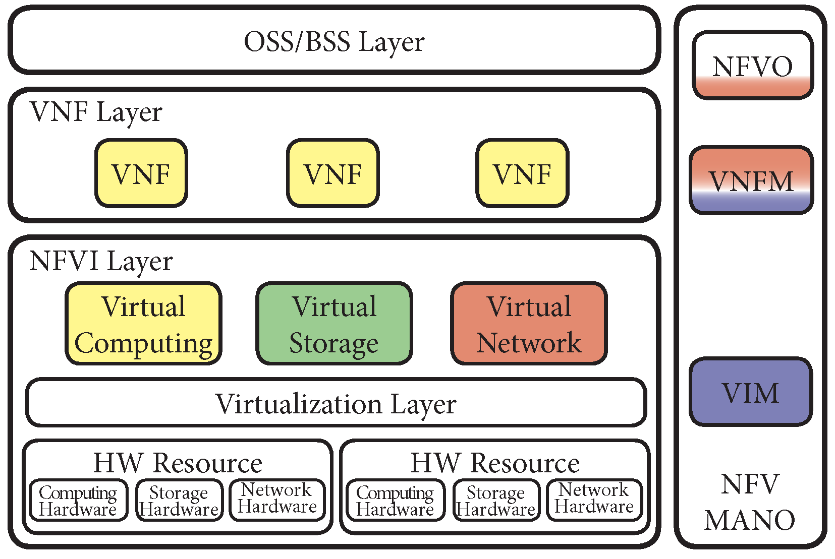
4.4. Relationship with ETSI NFV Architecture
It is worth noticing that the Megalos architecture is partially compliant with the European Telecommunications Standards Institute (ETSI) Network Function Virtualization (NFV) architecture [
27]. In particular, using the ETSI terminology, Megalos implements the Network Function Virtualization Infrastructure (NFVI) Layer, the Virtual Network Function (VNF) Layer and part of the NFV Management and Orchestration (MANO) component, as shown in
Figure 1.
The Docker container engine provides the Virtual Computing module and the VNF Layer (yellow colour in
Figure 1), while Kubernetes implements the Virtualized Infrastructure Manager (VIM) component. Megalos relies on Kubernetes also for some of the VNF Manager (VNFM) functionalities, such as VNF failure handling, scaling or updating. This is represented with the blue colour in
Figure 1. The Virtual Storage module, marked in green, is provided by Kubernetes through a multitude of supported drivers [
28].
The custom network plug-in described in
Section 5 (in red in
Figure 1) implements the Virtual Network module of the NFVI layer.
The VNFM component of the NFV MANO is provided by the Megalos Controller (in red in
Figure 1). Moreover, the Megalos Controller also implements some features of the NFV Orchestrator (NFVO). On the other hand, observe that Megalos cannot be classified as an ETSI NFV orchestrator, but rather as a network scenarios emulator. As described extensively in [
29], there are many NFV orchestrators such as: OpenStack’s Tacker, OSM, ONAP, CloudNFV, OPNFV, or CloudBand. Among these NFV orchestrators, OPNFV is attracting an increasing attention. It is worth to remark, however, that Megalos and OPNFV have different purposes. In fact, while Megalos is a distributed network emulation system that embodies some orchestrator functions, OPNFV is a general purpose orchestrator for the development of virtual network functions.
5. Megalos Networking
In this Section, we give a detailed explanation on how we designed the networking stack of Megalos, devised to meet the goals of
Section 3.
5.1. Data Plane
One of the main constraints of the architecture is that each packet generated by a Pod interface and sent outside a worker node must be routable to the correct destination by the cluster network. Moreover, the original packet must not be modified (see
Section 3.1).
Several strategies are possible for implementing a data plane for the virtual LANs, provided that the cluster network is an L3 network (see
Section 4.1) and the packets sent by VDs are not modified (see
Section 3.1). Such strategies are described below.
Assign routable IP addresses to Pods: A first possibility is to assign to Pod interfaces IPs that are routable in the physical cluster network, i.e., in the same IP realm. This strategy does not meet our goals since it rules out the existence of interfaces without any IP address and forces each virtual LAN to be an L3 network.
Map each virtual LAN to a specific VLAN: A second possibility is to constrain worker nodes to add specific VLAN tags to packets sent from Pod interfaces according to their virtual LAN. However, this strategy would require the cluster network to be a L2 network and a manual configuration on the physical switches. For these reasons, this solution does not satisfy our goals.
Use an SDN approach: A third option is to rely on an SDN controller and to install into each worker node an SDN-compliant virtual switch (as an example Open vSwitch [
30]). This choice requires to automatically devise OpenFlow rules that are installed by the SDN controller into the virtual switches to emulate the LANs. This can be done in several ways. As an example, one could trigger a suitable
PacketOut in all the switches that are recipients of a packet. As another example, one could encapsulate each packet into an L3 packet and send it to the network. The first alternative does not scale since the routing of each packet involves an interaction with the SDN controller. The second alternative is discussed below.
Rely on a custom encapsulation: A fourth option is to devise a custom encapsulation protocol to encapsulate L2 frames into L3 (or above) packets. This strategy has been adopted in [
20]. We discarded this solution since it relies on non-standard protocols.
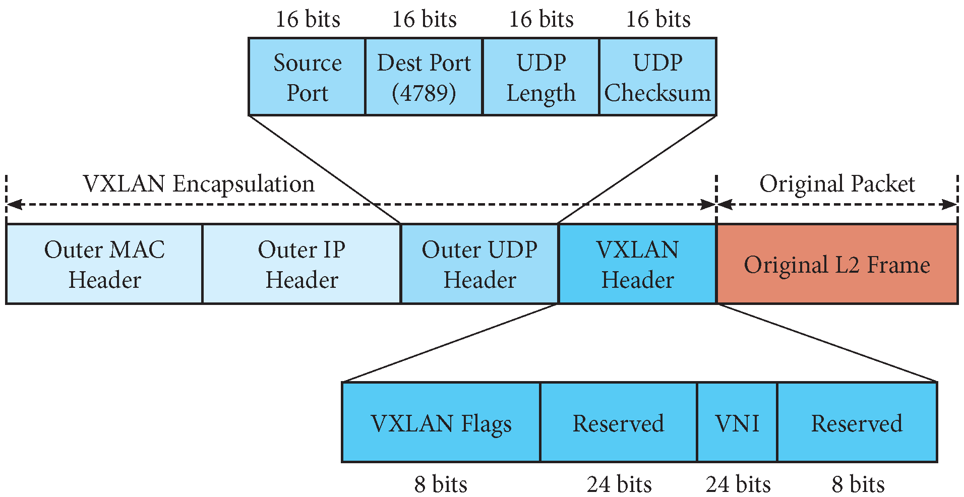
Use VXLAN [31]: The fifth choice is to use VXLAN, a standard protocol to transport Ethernet frames through an IP network based on MAC-in-UDP encapsulation.
Like CrystalNet [
22], Megalos Networking leverages on VXLAN. Indeed, VXLAN is an open standard, it is widely adopted in real networks, and it is supported by modern network equipment. Also, VXLAN is suitable for a possible hybrid network scenario (see
Section 6), since both physical and virtual portions of the network can make use of this technology. Another advantage of this choice is the L4 encapsulation, since packets may traverse NAT and L4 firewalls, and such middle-boxes filter out traffic without an L4 header.
Each virtual LAN is mapped into a VXLAN Segment and it is identified by a VXLAN Network Identifier (VNI). It is possible to manage up to ∼16M VNIs. The overlay network endpoint (analogous to a VPN termination point) is called VXLAN Tunnel End Point (VTEP). VXLAN behavior is the same of a switched L2 LAN: there is a MAC-to-VTEP table that is filled with a flood-and-learn policy. Precisely, the first Ethernet frame directed to an unknown destination is sent to an L3 multicast address, which corresponds to the VXLAN Segment associated with the virtual LAN. Hence, the packet is received by all the VTEPs of that VXLAN Segment (i.e., by all the nodes hosting interfaces on that virtual LAN). When a VTEP receives a packet, it records in the MAC-to-VTEP table the association between: the source MAC address, the VNI of the VXLAN Segment; and the IP unicast address of the VTEP hosting that specific MAC address. After this initial learning phase, Ethernet frames are only sent to the IP unicast address associated with the destination MAC address, reducing the need of multicast traffic. Thanks to the MAC-to-VTEP table, each VTEP can also reply to the ARP requests originating from its VXLAN Segment without forwarding them to the whole network (acting, in fact, as a proxy).
The ability of VXLAN to simulate a switched L2 LAN is so effective that it works even if there are two interfaces with the same MAC address belonging to different Segments, just as a real network does.
As shown in
Figure 2, VXLAN adds only 50 bytes of overhead to the original packet, so the network’s MTU is not dramatically reduced. Therefore, only very large packets will require fragmentation.
Observe that VXLAN payload is not encrypted so that VXLAN packets are subject to be sniffed and read through the network. If confidentiality is required, IPSec could be used to encapsulate the entire VXLAN packet (it is not possible to use IPSec to encapsulate the VXLAN payload only, since it is an L2 packet). Of course, this alternative would yield a larger packet size overhead. We consider these security issues out of the scope of our paper.
5.2. Control Plane
The VXLAN flood-and-learn process has two drawbacks. The first is that it relies on IP multicast to populate the MAC-to-VTEP table, which may not be possible as the Internet does not necessarily guarantee IP multicast packets forwarding. The second problem is that if a container
c is created on a worker node, its interfaces and their MAC addresses in the MAC-to-VTEP tables of the other worker nodes of the cluster will not be updated till
c sends its first packet. In order to overcome these drawbacks we need to replace the flood-and-learn process with an alternative control plane. This could be done with standardized or non-standardized technologies. There are many downsides in using non-standardized ones, although they have been sometimes proposed. For example VXFLD [
32] implements a custom control plane for VXLAN. In our solution we leverage on Ethernet VPN (EVPN) BGP, since it is standardized in [
33] and widely used in large data centers [
34].
EVPN is a model for exchanging control plane information (in our case MAC-to-VTEP tables) using BGP updates. The BGP daemon is able to read and inject information into the VXLAN data plane so that packets will be correctly encapsulated and routed. When a container c is started on a worker node w, the BGP daemon associated to w announces the MAC address, VTEP, and VNI of all the interfaces of c, so that all the other peers can update their tables.
To support EVPN BGP while keeping Kubernetes unaware of the presence of such protocol, we put the BGP daemon into a dedicated container, instead of installing it directly into the worker node. To make this solution work, the container needs visibility of the worker Linux network namespace. In this way, it is able to read and inject information directly into the MAC-to-VTEP tables of the physical worker. An instance of this container, wrapped into a Pod, is deployed on each worker node, using the Kubernetes DaemonSet object [
35].
Additionally, another Pod, configured as a BGP Route Reflector [
36], is deployed on a worker node elected by Kubernetes. This Pod is wrapped by a Kubernetes Service [
37], so it has a Service IP address that is automatically reachable by each other Pod in the cluster. The Route Reflector accepts dynamic BGP peerings, so it does not require further configuration. Briefly, when a new worker node is added to the cluster, the DaemonSet deploys on it an instance of the worker BGP daemon, and it establishes a peering with the Route Reflector through the Service IP Address. In conclusion, using the Route Reflector significantly simplifies the BGP setup, avoiding the full mesh peerings between worker nodes. Also, the dynamic peerings of the Route Reflector overcome the need of manually configuring all the worker IP addresses in the BGP control plane.
The solution described above is shown in
Figure 3. In the figure two Kubernetes worker nodes are shown. Each node hosts some Pods (blue boxes), as scheduled by the Kubernetes master node. In particular,
podX,
podY,
podZ, and
podA represent VDs with several user-defined interfaces. Such interfaces are associated with suitable VTEPs (green boxes) corresponding to the virtual LANs. In each worker node there is also a
podBGP hosting a BGP daemon configured using EVPN BGP, which is updated according to the MAC addresses belonging to the VTEPs (dashed lines). All the BGP daemons peer (dotted lines) with a BGP Route Reflector running on a specific Pod (
podBGP RR) which is unique in the cluster.
5.3. The Megalos Container Network Interface
Each VD may have several virtual interfaces. In addition to the virtual interfaces required by the user, there is also a mandatory management interface used by Kubernetes (for heartbeat functions, etc.). Kubernetes delegates the management of network interfaces to suitable CNI plug-ins. For the management interface any available CNI plug-in can be used (e.g., [
38,
39,
40]), including the Kubernetes default KubeNet CNI. All these CNIs assign to the management interface an IP address chosen in a specific pool which is routable in the cluster. Hence, the management interface belongs to an L3 network. On the other hand, since Megalos offers L2 interfaces to the VDs and enforces traffic segregation among virtual LANs (
Section 3.1), no traditional CNI can be used to manage the user-defined interfaces.
Therefore, we implemented a custom CNI plug-in, called
Megalos CNI. Megalos CNI is not directly invoked by Kubernetes. Kubernetes, instead, invokes the Multus CNI plug-in which, in turn, invokes an instance of Megalos CNI for each virtual interface assigned to the VD. When a new Pod representing a VD is created on a worker node, the Multus CNI plug-in, by using the etcd [
41] distributed key-value store, retrieves from the master node the virtual LANs configuration which contain the VNIs identifying the needed VXLAN Segments. For each VXLAN Segment the worker node is aware of, there exists in the worker node a VTEP and a
VTEP companion bridge. The Multus CNI plug-in passes to each instance of the Megalos CNI the parameters of its virtual LAN. Using such parameters, the Megalos CNI checks if the VTEP companion bridge already exists in the worker node, and creates it if it doesn’t. Then it attaches the virtual interface of the VD to the VTEP companion bridge.
6. Use Cases
In this section we illustrate the flexibility and scalability of Megalos by describing three possible use cases. In particular, we focus on using Megalos for setting up network scenarios that can be: (i) large, (ii) heterogeneous, and/or (iii) hybrid.
Large Networks: Megalos can be used to emulate large scale network infrastructures. These scenarios may require a huge quantity of VDs and virtual LANs. Hence, running them on a single node would be unpractical since a workstation with a great amount of resources would be required. We give two examples.
A large network that we emulated with Megalos is the one of a data center, structured as a Clos [
42,
43]. Clos topologies were formalized in 1952 to implement non-blocking, multistage switching architectures [
42]. Their design was recently redefined and adapted to be used in large scale data centers under the name of Fat-Trees [
44,
45]. Details on the emulation of this kind of networks are provided in
Section 7.
As a second example, Megalos can be used to perform a high-level emulation of the entire Internet interdomain routing, provided that a suitable number of worker nodes is available. More precisely, each Autonomous System (AS) can be mapped to a single BGP router and the CAIDA ASRank [
46] database can be used to create a set of BGP customer-provider peer policies. The generated network scenario will count about 100k VDs [
47] and about 350k virtual LANs [
46]. In this scenario, ASes need to announce their real IP prefixes, so it is not possible to emulate it without a tool that allows the usage of globally routed IP addresses and that isolates the virtual LANs from the cluster network. In the hypothesis of placing 1K Pods per worker, Megalos would need a total amount of 100 workers. We remark that the emulation in a testbed of the interdomain routing of the Internet has been a challenge for years [
48]. Observe that DRMSim [
49] tries to solve this problem with a discrete event simulator.
Heterogeneous Networks: The flexibility of Megalos allows (by creating proper Docker Images) to emulate a variety of network devices, such as SDN switches or P4-compliant devices [
50]. In particular those two kind of devices are very expensive, hence being able to emulate them would help researchers to experiment with those technologies without having to buy any physical device. Megalos has been successfully tested with the already available Docker images [
51] running OpenVSwitch [
30] or P4 behavioral model. As an example, if the user wants to emulate a network scenario containing a P4-compliant device
d, it is sufficient to perform the following steps: (1) A Docker image containing the P4 Behavioral Model (BMv2) must be created and pushed to the Docker Hub (observe that one of such images is already published). (2) In the description file of the network scenario, the aforementioned Docker image is assigned to
d. (3) The P4 source code to be used by
d must be added to the configuration files of
d. (4) When the network scenario is deployed the configuration for
d is read and the BMv2 daemon is automatically started.
Hybrid Networks: Network virtualization is gaining an ever growing attention of both the scientific community and the industry. One limit in the adoption of this paradigm is that migrating in just “one step” from a physical network to a virtual one is overly complex without breaking the service continuity. Hence, transition methods and tools allowing the co-existence of physical and virtual devices are especially useful (see, for example, the survey [
52] for NFV technology). Megalos can be exploited to support this migration. In fact, it is possible to configure a physical router to announce the physical network’s MAC Addresses to the virtual portion of the network and vice-versa, allowing the communication between them. To achieve this, it is needed to configure EVPN BGP on a physical router with a peering to the route reflector of the Kubernetes cluster. With this hybrid scenario, it is possible to transpose each physical device into its (one or more) virtual counterpart without any changes in the configuration of the other portion of the network.
7. Evaluating the Scalability
To assess the efficiency and effectiveness of Megalos we implemented the Architecture described in
Section 4 (source code and testbed used in this paper are available at [
53]).
As we said in
Section 4.3, any suitable language can be used to describe a network scenario that has to be realized with Megalos. In any case, in order to perform the experiments described in this section we used the same language of Kathará and the Megalos Controller is realized using a modified version of Kathará that uses Kubernetes APIs.
We performed the following four experiments.
Virtual LAN Scalability: We performed tests to check if Megalos can concurrently manage a large number of virtual LANs.
Virtual Device Scalability: We designed Megalos in order to manage, even on cheap clusters, large network scenarios where each VD can be as complex as a network device. Hence, we verified that Megalos can emulate a large number of VDs each equipped with a fully fledged network protocol stack.
Latency Scalability: A weak point of complex architectures (like Megalos) is that they might introduce unnecessary latency. Hence, we performed tests to measure the impact of Megalos on the latency of the virtual network.
Startup Scalability: We measured the time required to startup a network scenario first by just using Kathará (single- and multi-thread) and then by using Megalos (single- and multi-worker).
7.1. Virtual LAN Scalability
To demonstrate that Megalos can achieve scalability in terms of number of virtual LANs, we measured the amount of virtual LANs that can be deployed in a cluster. The results of the test were very positive. Indeed, we were able to start on a single worker more than 500K different virtual LANs distributed among 1000 VDs. However this does not come for free: starting a high number of virtual LANs on the same worker implies spending a considerable startup time. Indeed, our experiment took about 90 min on a worker equipped with dual Intel Xeon Gold 6126 CPU, 768 GB of RAM, 9× SAS SSDs Raid 5, and Debian 9 as OS.
7.2. Virtual Device Scalability
The cluster used in the experiments described in this test is composed of 50 cheap physical nodes, each one equipped with Intel Core i5 4590T CPU, 8GB of RAM, mechanical HDD and Debian 9 as OS. To test the VD scalability, we used Megalos to implement the virtual network of a small data center consisting of about 2K VDs. The topology is the one of a Fat-Tree Network, analogous to that described in
Section 6. In the network there are 2048 servers, each containing an Apache Webserver (using 20 MBytes of RAM), and 128 ToRs, 128 Leafs, 64 Spines, and 2 Exit Nodes, each equipped with a fully-fledged FRRouting [
54] daemon (using 10 MBytes of RAM). Hence, we have an average of 48 VDs per worker. The test was successful, we were able to smoothly run the entire topology and we ensured that all hosts were reachable each other. Megalos was able to startup the network scenario in our low-performing cluster.
7.3. Latency Scalability
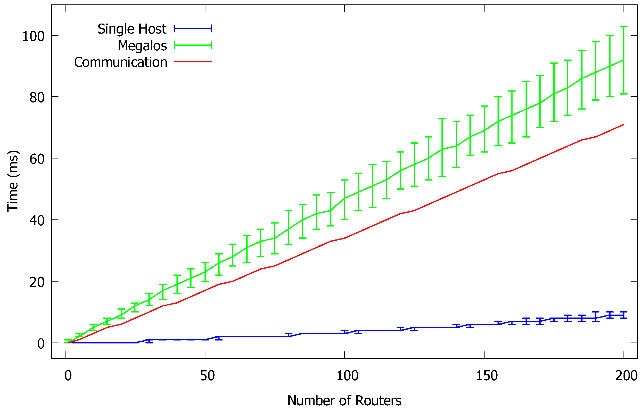
To measure the latency overhead induced by Megalos, using the same cluster of the previous experiment, we realized a network scenario consisting of a chain of VDs, for different values of n, where:
The first and the last VD of the chain are a client and a server, respectively;
All the intermediate VDs are routers; and
Two VDs that are consecutive in the chain are connected by a virtual LAN.
Also, we tampered the Kubernetes scheduler so that two VDs that are consecutive in the chain are never allocated to the same worker. Using plain
ping we measured the Round-Trip Time (RTT) between the client and the server. We performed the above experiment ranging
n from 0 to 200. The measured average RTTs are in
Figure 4 with the green curve (standard deviation is also shown).
In order to obtain the RTT overhead actually introduced by Megalos, we need to subtract from the above described values the intrinsic latency of the containers and the latency due to the physical network. Therefore, we performed the following additional measures.
Finally, for each value of
n, we summed up the RTT measured in the single host scenario with the average latency of the physical network multiplied by
n. The red curve of
Figure 4 shows the result. The difference between the green curve and the red curve is the overhead latency introduced by Megalos. It appears that such overhead is linear with the number of consecutive VDs traversed by the traffic that are allocated to different workers.
7.4. Startup Scalability
We performed three different types of experiments.
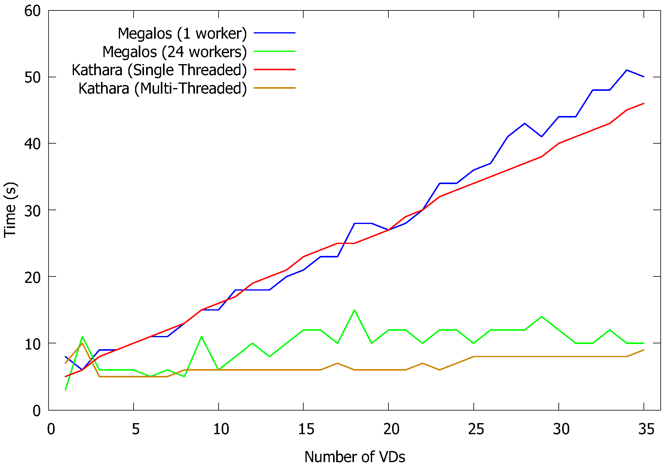
In the first experiment, we focus on measuring Megalos performance with respect to the amount of time needed to deploy network scenarios compared with Kathará. In particular we used Kathará version 3.10 both with the default multi-thread execution, and forcing a single-thread execution. In contrast, we measured the startup times of Megalos both with one worker and 24 workers. We ran this test over several network scenarios, increasing the number of VDs. The results, shown in
Figure 5, highlight the ability of Kubernetes of schedule VDs in a distributed way. It is apparent that Kubernetes takes advantage of the number of worker nodes (horizontal scalability) more efficiently than what it gains by increasing the number of threads (vertical scalability). Conversely, Kathará, being single-host, is favored only by increasing the number of threads. From
Figure 5 it appears that single-worker Megalos has startup times equivalent to those of single threaded Kathará and that multi-worker Megalos has startup time equivalent to those of multi-threaded Kathará.
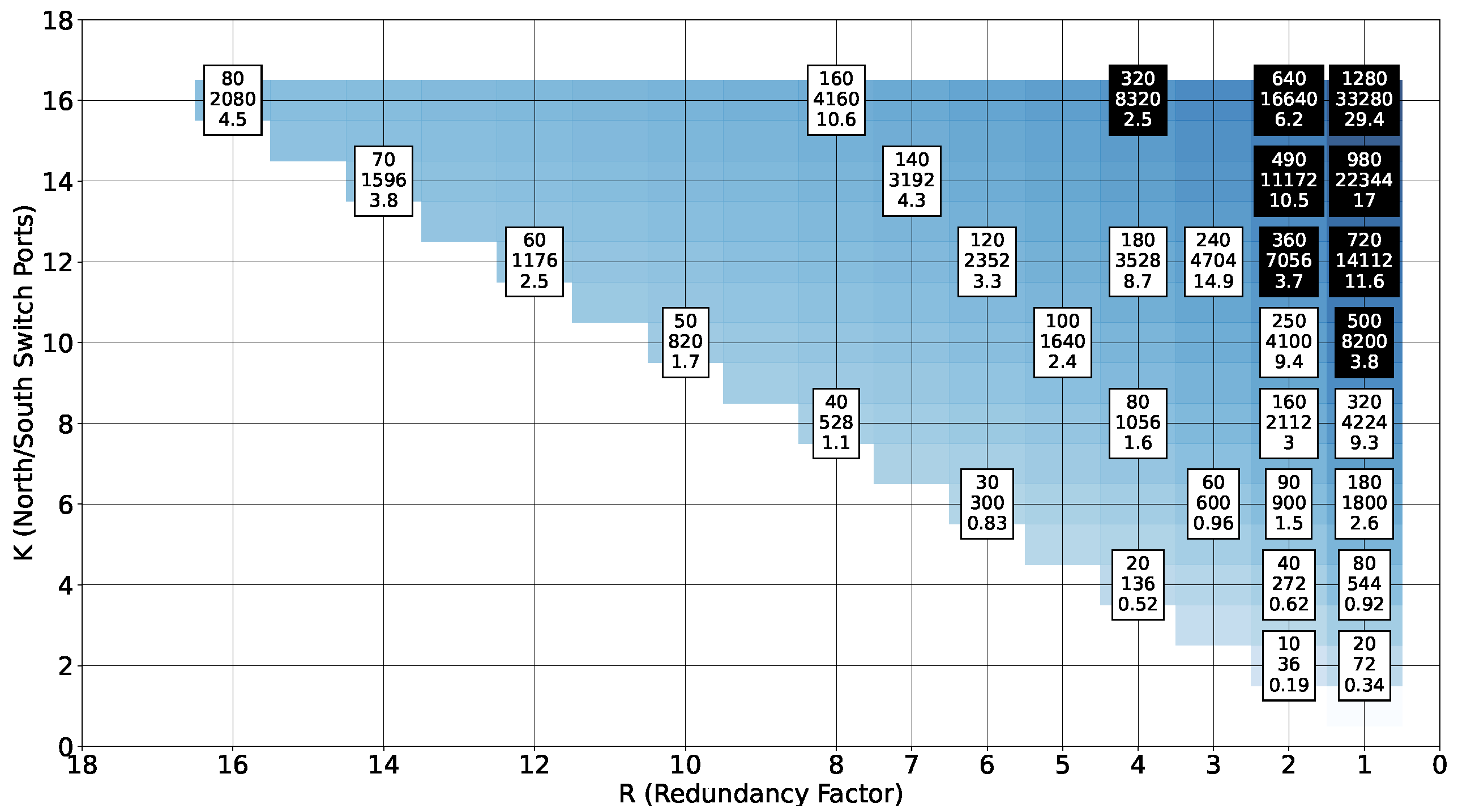
In the second experiment, focusing on the application of Megalos to a real-life networks, we considered the startup time of Fat-Tree networks, which are commonly used in data-centers.
Figure 6 shows the number of VDs, the number of interfaces, and the startup time in minutes (average of five measures) depending on the fundamental parameters
K (north/south switch ports) and
R (redundancy factor, a divisor of
K) of the Fat-Tree. Each VD of the Fat-Tree has
interfaces and the number of VDs is given by the formula
[
55]. In
Figure 6, the color intensity of the blue heatmap in the background is proportional to such a number. In particular, we have networks with number of VDs ranging from 10, for
, to 1280, for
. White boxes correspond to experiments performed on a local virtual cluster composed of 22 worker nodes, each with 2-core vCPUs and 8 GB of vRAM. Black boxes correspond to experiments performed on an Azure cluster composed of 160 worker nodes, each with 4-core vCPUs and 8GB of vRAM.
As expected, the startup times increase with the number of VDs. Notice that the startup times also strongly depend on the number of interfaces. For example, the networks generated for
and
have the same size in term of VDs, but a different number of interfaces, and this strongly impacts the resulting startup time. As it was the case for the previous measures, it is apparent that Megalos takes advantage from the size of the available cluster. The startup times are much lower for the Azure experiments (black boxes of
Figure 6) with respect to the local cluster (white boxes). Overall the startup times are, in our opinion, acceptable for practical use. The largest network (1280 VDs and 33,280 interfaces) was launched in about half an hour.
Motivated by the result of the second experiment, in the third experiment we measured the impact of the number of virtual interfaces on the startup time. In particular, we launched a single VD with an increasing number
n of virtual interfaces, with
n ranging from 1 to 150.
Figure 7 shows that the dependency of the startup time from the number of interfaces is linear, which again confirms the scalability of the Megalos architecture.
8. Conclusions & Future Work
We proved that, by using off-the-shelf container-based technologies (Docker and Kubernetes) and standard network protocols (VXLAN and EVPN BGP), it is possible to build a framework that allows us to emulate in a distributed environment large and complex network scenarios. In particular, we presented Megalos, a scalable, and distributed architecture, that supports the implementation of virtual network scenarios consisting of several networking devices (VDs) where each VD:
can implement a fully-fledged network device and
can have several Layer 2 interfaces, each connected to a virtual LAN.
Some problems, mainly of technical nature, remain open.
Megalos architecture inherits from Kubernetes some limitations. For example, when the latency among the cluster nodes is too high, Kubernetes is not guaranteed to work as worker nodes appear to be unreachable due to the Kubernetes timeout values. This may cause problems when the cluster is geographically distributed among weakly connected sites. Empirically, we measured that 300 ms of delay among two cluster nodes is a too high value for Kubernetes to work properly.
A second limitation is that Kubernetes currently supports containers only and does not support virtual machines. This rules off hybrid VM/container scenarios which would allow us to emulate network functions that are impractical to containerize. Examples of such non-containerizable devices are those that need additional kernel modules or specific kernels different from the Kubernetes worker ones. These include devices using a different Operating System; platform using the Soft-RoCE [
56] kernel module; some vendor router images distributed via VM only; etc. A solution to this limitation could come from the project KubeVirt [
57], aimed at allowing Kubernetes to also manage VMs. The compatibility of KubeVirt with Megalos architecture and, in particular, with Megalos CNI has to be further investigated.
A third limitation inherited from Kubernetes is that IPv6 is not yet fully supported for the addresses of the cluster nodes. We remark, though, that Megalos emulation pushes itself down to Layer 2, allowing arbitrary Layer 3 protocols for the virtual LANs, including IPv6. IPv6 support in Kubernetes will be likely introduced in the future versions (up to now it is only provided in the beta version).
A limitation of Megalos coming from the use of Multus CNI is the impossibility to dynamically modify the number of network interfaces after the VD’s deployment. Until Multus CNI does not support the dynamic creation and deletion of network interfaces, this limitation cannot be easily addressed.
In addition to solving some of the limitations above, future work include the following.
Investigate the technical feasibility of using Kubernetes instances provided directly by public clouds like Amazon Web Services, Microsoft Azure, or Google Cloud Platform. This would improve the usability of Megalos and reduce the costs of an emulation.
Improve the flexibility of Megalos by allowing external software components to interface with it, leveraging on standard protocols (e.g., via REST APIs).
Support IPSec for the connections among VTEPs in different worker nodes, allowing the encryption of the traffic flowing into virtual LANs.
Use Megalos to perform an emulation of the current network of the Autonomous Systems in the Internet.


