1. Introduction
The Brazilian territory holds around 12% of the world’s total freshwater [
1]. Such a precious asset deserves careful management to preserve its quality and to avoid wastes in water distribution systems.
However, approximately 40% of the water flowing through the Brazilian water supply systems in Brazil is lost. The waste represents almost 7000 Olympic pools of drinking water per day, generating a financial loss above USD 3 billion every year. The reasons for these losses are diverse: leaks, measurement errors, or even water theft.
Smart water management in supply systems is essential to optimize the use of water resources and the quality of service. In this context, the Internet of Things (IoT) can be a valuable tool, as it enables the integration of multiple technologies, storing and analyzing data from different sources in real-time, and extracting contextual information.
It can be difficult to anticipate all operational scenarios in IoT-based systems and to establish how managers should act in each situation. Modeling these operational processes through conventional workflows (e.g., Business Process Model and Notation (BPMN) [
2]), based on fixed flows, is a considerable challenge. In this situation, the flexibility provided by declarative processes can be an adequate solution to deal with water systems. The declarative paradigm allows the execution of every activity provided it is not explicitly prohibited in the process specification [
3]. Thus, it ensures that only activities that do not violate the policies of management will be executed. This paper demonstrates the advantages of adopting declarative processes in the context of water management systems through an illustrative example. The paper models a real water system using both process paradigms: declarative and imperative. Then it compares each model to evaluate its potential and limitations.
After drawing the model, the process implementation phase took place. However, feeding the process in real-time with information that originates from the sensor network is a complex task, since the amount of data generated by the environment increases exponentially. Hence, there is a strong need for identifying information patterns hidden in such a data storm. To address this challenge, this paper exploits the Complex Event Processing (CEP), which is capable of dealing with the analysis of large amounts of data in real-time, and identifying patterns and relationships between distinct events.
This paper proposes an IoT framework for intelligent water management, called REFlex Water. It uses declarative processes to model the water system. A process represents policies and the infrastructure required to control the water distribution, allowing operators to handle routine situations and unforeseen occurrences. REFlex Water implements the process using CEP technology. The paper tests the implementation performance to evaluate the framework’s capacity to respond to scenarios with a high number of IoT devices and heavy data traffic.
The main contribution is to provide a framework for smart water management, which provides efficiency in measuring and identifying leaks based on an IoT infrastructure. An additional contribution is the use of declarative processes to represent water management policies. Such a process modeling paradigm allows for the implementation of ordinary controlling policies but also offers the necessary flexibility to handle unforeseen situations.
Table 1 shows the comparison of REFlex Water with other Frameworks. The characteristics C1 to C9 observed are as follows: use of declarative processes (C1), use of CEP (C2), monitoring system (C3), intelligent measurement (C4), energy management (C5), real-time data analytics (C6), monitoring water quality (C7), leak detection (C8), sending alerts (C9). The bullets refer to characteristics supported, while the minus to characteristics unsupported.
Among the frameworks, it was observed recurring characteristics presented by SWAMP, Navarro-Hellín et al. [
5], EARNPIPE and SMWQC that make these solutions similar to REFlex Water, where they use monitoring systems, intelligent measurement, and real-time data analysis. However, they are also similar in the absence of the use of complex event processing, or declarative processes. REFlex Water differs from the other frameworks, precisely because it contemplates the use of declarative processes and processing of complex events. On the other hand, REFlex Water does not include energy management and monitoring water quality.
2. Motivational Scenario
This work uses a real water monitoring system running in the Brazilian city of Teresina as the motivational scenario. The system monitors critical information such as water flow, pressure in the pipes, and tank levels, among others. A set of IoT devices where installed throughout the water infrastructure to capture such information. The main concern was to avoid water losses and interruption in the water supply. This work will focus on the subsystem of water prevention.
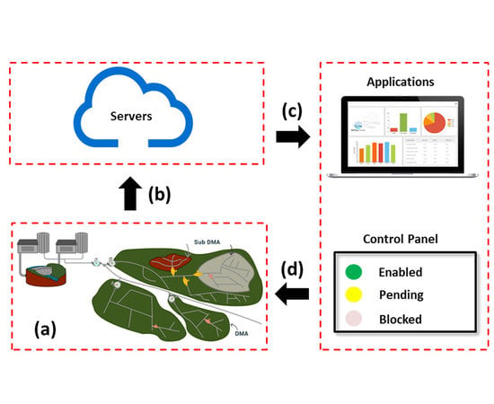
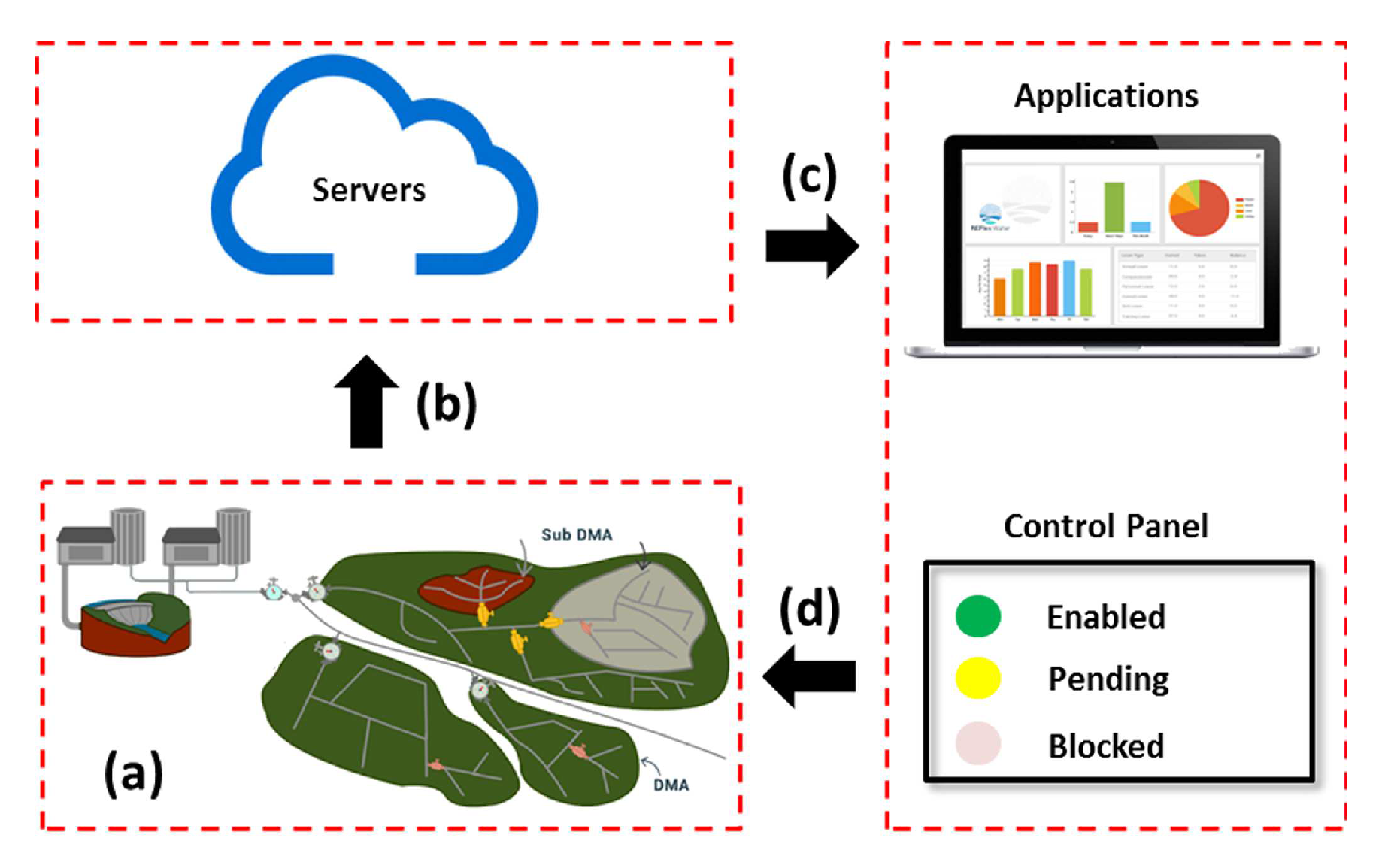
Figure 1 illustrates the monitoring framework implemented in this paper: (a) sensors installed in the water supply system collect data and send to servers; (b) servers use CEP technology to process data from the sensors in real-time, in order to identify recurring patterns of water loss; (c) alarms are triggered upon the occurrence of water loss; (d) water management agents take action to solve the problem, executing one or more tasks enabled in the control center panel. A declarative business process controls the enabling and disabling of tasks in the control panel.
3. Related Work
The Internet of Things (IoT) is a dynamic wireless network infrastructure that integrates various communication technologies and solutions to enable the interaction between people and things/objects [
8]. This remarkable technology opens opportunities for the development of distinct applications for the so-called smart cities. For instance, in the context of water management, the use of IoT allows for monitoring and controlling water supply systems in real-time.
A literature review on the use of IoT technologies for water management confirms that this theme has been the focus of a number of recent works. However, most of these research papers are largely engineering works. They focus on the IoT infrastructure itself to demonstrate and evaluate some implementation possibilities. Other works address innovative strategies for analyzing the copious amounts of data generated by the sensors. They want to identify patterns (e.g., water leakages) through big data technologies that usually do not present adequate response time in the context of water systems. Unfortunately, in real life scenarios, the analysis must produce results in real-time. Otherwise it may be too late to take the necessary actions to handle issues in the water supply systems. Therefore, efficient mechanisms are required to control and operate these systems, preventing undesirable incidents in real-time.
The dynamic behavior of water supply systems requires the flexibility to deal with unpredictable situations. At the same time, it is necessary to maintain strict control to respect the operational and strategic policies defined by water management companies. This paper suggests the use of declarative business processes to provide flexibility and control in the operations of water supply systems. To confirm these facts, we present below a summary of the main works related to the theme addressed in this paper:
Jadhav et al. [
11] developed an automatic system for measuring water quality in real-time. The system uses water pH, turbidity, and temperature levels to determine the quality of the water. The data collected is sent to the Global System for Mobile Communications (GSM) monitoring center in the form of a Short Message Service (SMS). If water does not present the expected quality level, it sends data to the management center and mobile devices. The solution is low cost and does not require personnel to be on call. However, the work is limited to water quality measuring. It does not address other aspects of water supply systems, such as water leakage or interruption of water supply.
Robles et al. [
12] proposed an architecture to describe physical water scenarios to allow the integration of water equipment into an interoperable environment. The authors claim that the use of a platform-independent service-oriented architecture would simplify the integration of new water equipment. They evaluated the architecture through an experiment conducted in their laboratory to demonstrate the application of their architecture. In the context of water supply systems, it is essential to understand the performance behavior of the solution. Unfortunately, the experiment does not evaluate the performance of the proposed architecture.
Shah [
13] implemented an IoT infrastructure that includes water flow sensors, water control valves, and a raspberry PI core controller. They use a web interface to monitor and control the water system to ensure equal water distribution to each connection point. This solution is a typical engineering work that demonstrates the practical implementation of infrastructure in a specific context. Hence, it is very difficult to replicate their work or apply their solution in water systems with different characteristics.
Jo et al. [
10] used CEP rules to detect real-time leaks in a water supply system. Water flow meters are installed in the system to monitor the pressure and flow rate of each block. In addition, they developed a visualization tool that displays on a map the leaks detected by the CEP. The work is based on imperative processes to control the behavior of water systems. Therefore, managers must anticipate all operational scenarios, reducing the flexibility of the solution.
Yang et al. [
14] proposed an intelligent application for real-time monitoring of water supply systems based on CEP technology to anticipate risks and to control devices remotely. Despite having the objective of monitoring in real-time, the work does not demonstrate the scalability of the solution in a real environment. Moreover, the paper does not take into account the flexibility that water management processes need.
Allen et al. [
15] developed a platform called WaterWiSe that manages and analyzes data from a water network through wireless sensors. WaterWiSe supports a variety of applications, including continuous water demand and hydraulic state forecasts, online detection of events such as pipe leaks, and data mining to identify long-term trends. They deployed a platform to represent water network management. However, their solution only takes into account the infrastructure, which generates reports to indicate the occurrence of predefined issues, but does not deal with the decision-making process.
Pesic et al. [
16] argue that replacing the imperative with the declarative paradigm is essential to make business process management more flexible. The authors demonstrated that the adoption of the declarative paradigm could (a) avoid changes in the business process to relax stringent rules, (b) provide support for changes at the instance level (ad-hoc change) and type (evolutionary change), and (c) simplify the distinction between mandatory and optional restrictions. The focus of their work is not water management systems.
Döhring et al. [
17] observed that existing reference workflow often has to be adapted according to specific contextual factors. The authors proposed extending basic changing operations, such as task insertion and removal, with a pattern catalog. The work only reinforces the need for more flexibility in workflow-based (imperative) processes.
Afflerbach et al. [
18] proposed an optimization model that takes into account the principles of value-based business process management, from an economic perspective, to determine the optimal level of process flexibility. The authors evaluated the model through an experiment conducted using production processes from an international company in the semiconductor industry. The work reinforces the arguments presented in this document: water management business processes must provide sufficient control to respect defined policies and the flexibility to allow all actions not to be restricted by those policies.
Thus, subsequent to the literature review and to the best of our knowledge, this is the first work to propose the application of declarative business processes to the efficient management of water systems based on IoT infrastructures.
4. Background
This section presents the basic concepts adopted for building the REFlex Water framework.
4.1. Declarative Process
Unlike imperative processes, the concept declarative defines a set of restrictive rules. As long as users respect these rules, they are free to choose how to execute the process [
19]. In the opposite direction, imperative processes specify how the users must execute the rules, stating all possible dependencies between tasks. This difference is fundamental for declarative processes in environments of uncertainty and constant change as in the field of water management.
Scenario
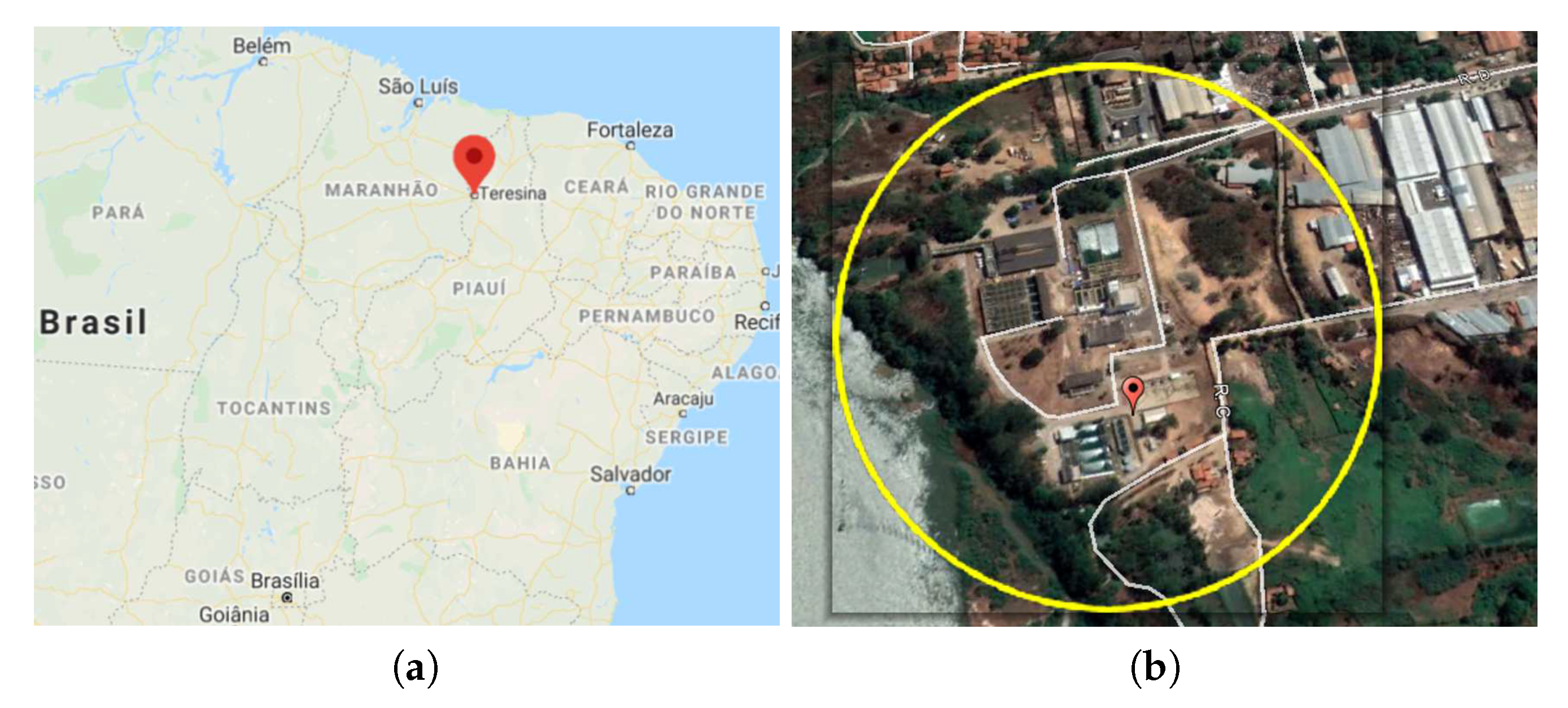
This paper uses a real water system from a Brazilian city.
Figure 2a shows the map of the northeast region of Brazil. It indicates the location of the water system used in this study.
Figure 2b highlights the area covered by the water system, using an image extracted from Google Earth.
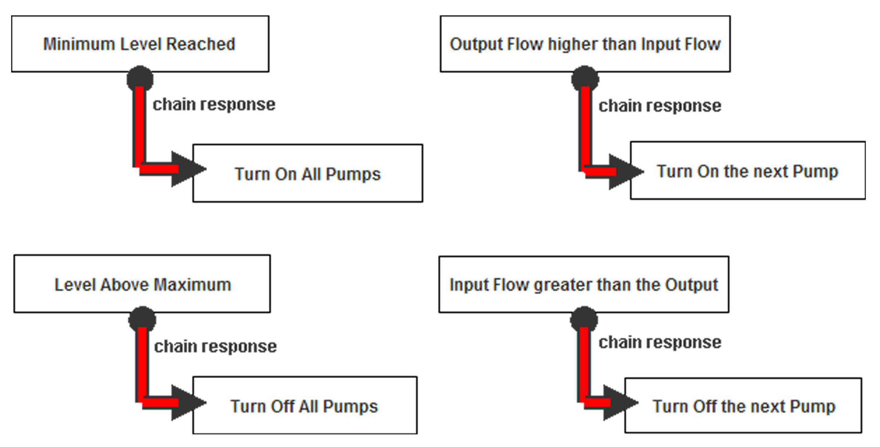
The scenario models a subsystem that consists of four pumps and a tank. The pumps draw water from a water treatment plant. The system adopts the following rules to control the real system:
All pumps are off at the beginning of the process.
It checks the tank level after a given predefined period.
Turns all pumps on when the tank reaches the lower level.
Turns all pumps off when the tank reaches the higher level.
Turns off the pump running for the longest period whenever the volume of water flowing to the tank is greater than the volume of water flowing out of the tank.
Turns off the pump running for the longest period whenever the volume of water flowing to the tank is lower than the volume of water flowing out of the tank.
For the sake of clarity, the scenario used in this paper does not include some of these rules. Examples include the treatment of defective pumps, pumps that need maintenance, lack of water at the source, excessive water turbidity, and problems in the tank.
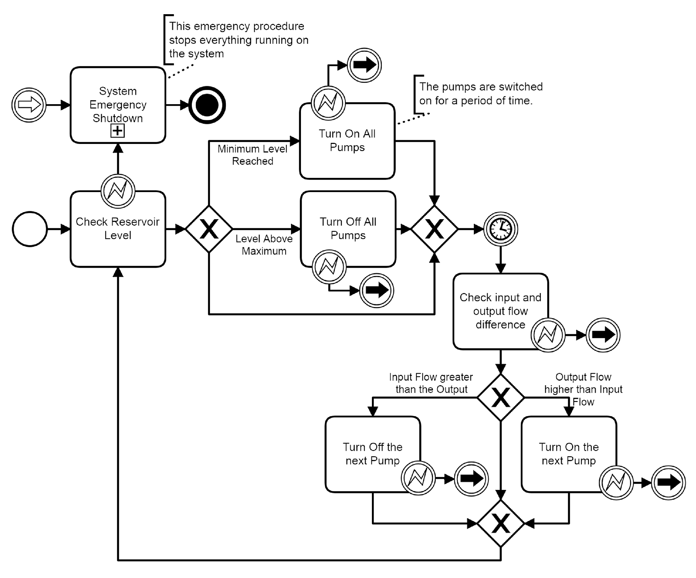
Figure 3 shows the process modeled in BPMN. Steps 1 to 6 are depicted in
Figure 3 and
Figure 4. These figures show representations in BPMN and in Declare of the six steps. In
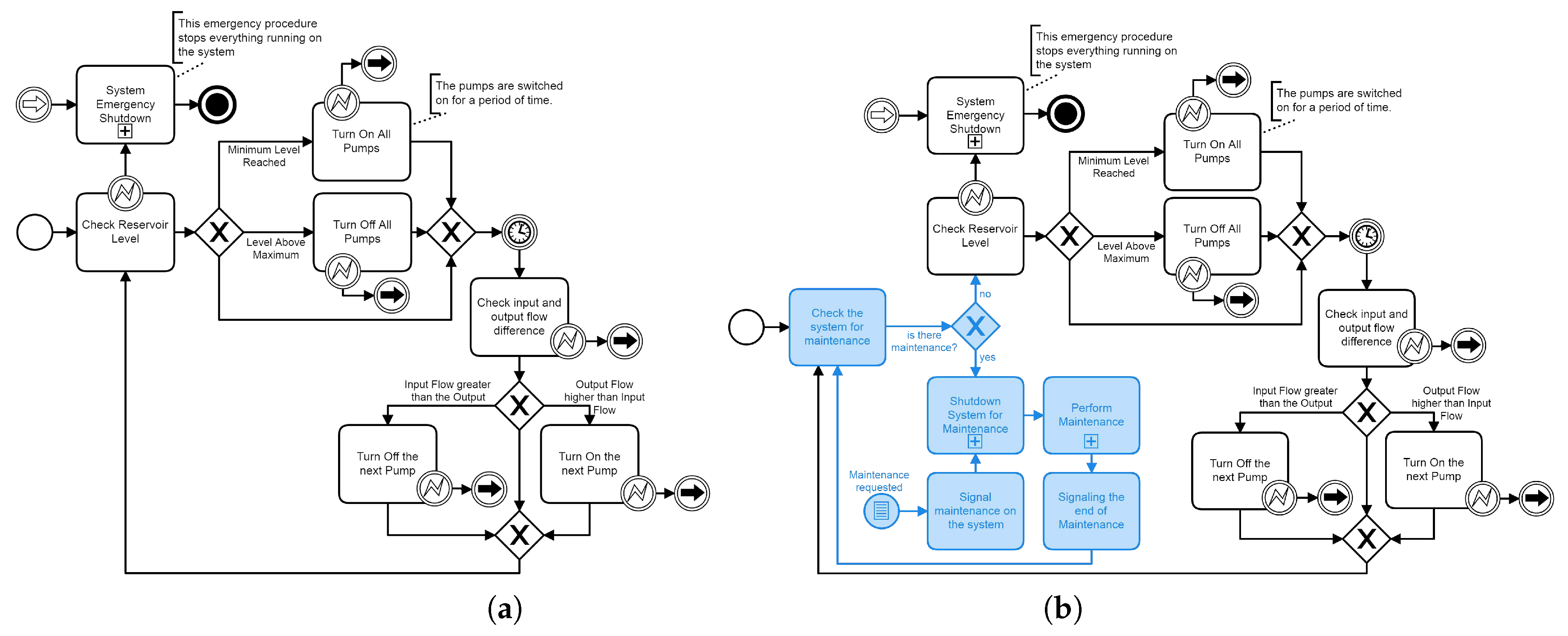
Figure 3 we see some error treatments that lead to a System Emergency Shutdown in the case of any problems during BPMN activities like Check Tank Level, or Turn on or Turn off pumps. As described in the list, the first activity is Check Tank Level: based on the result of this activity the system will turn on or turn off all pumps. After some time, a second activity will check the difference between input and output water flow and make another decision based on the result: eliminate one pump (turning it off) or turn on another pump (if it is some other pump to be turned on). This is an infinite loop that will stop only if another action outside of the model is performed. During the modeling phase, we noticed a significant impact on the complexity of the imperative process (
Figure 3) when any of the simplifications mentioned above are not assumed. For instance, the addition of a maintenance subprocess, which stops pumps for preventive maintenance or closes the tank for cleaning, duplicates the number of connections in the BPMN model. On the other hand, including the same rules in the declarative process (
Figure 4) has a negligible impact on the process complexity. In this case, to add an action to stop a pump and execute the preventive maintenance or to close and clean the tank would be enough.
The simplicity of the BPMN model is also its weakness when trying to when trying to devise a stop process for one or more pumps for preventive maintenance, or even a stop for tank cleaning or maintenance. On must rewrite the entire process to meet the need for unforeseen events.
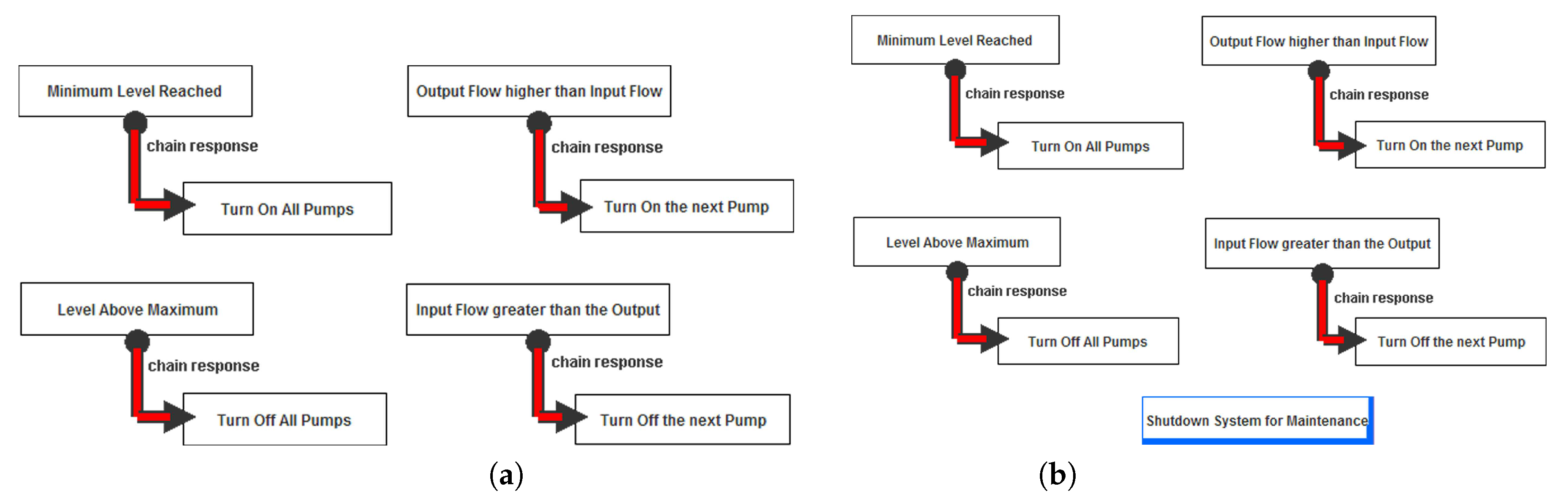
Figure 4 depicts the same process that was described before: the difference is the notation. As it is a declarative notation, there is no definition of the sequence of activities, only the constraints. The activities on this notation are the rectangles. There is just one kind of rule, which is an obligation of immediate execution, called a chain response. This rule implies that, whenever the source activity is performed, the next activity to be executed is the activity at the end of the rule. So after the Minimum Level Reached the next activity is Turn on All Pumps; after Output Flow higher than Input Flow, it will be Turn on the Next Pump, and so on.
4.2. Water Supply Systems
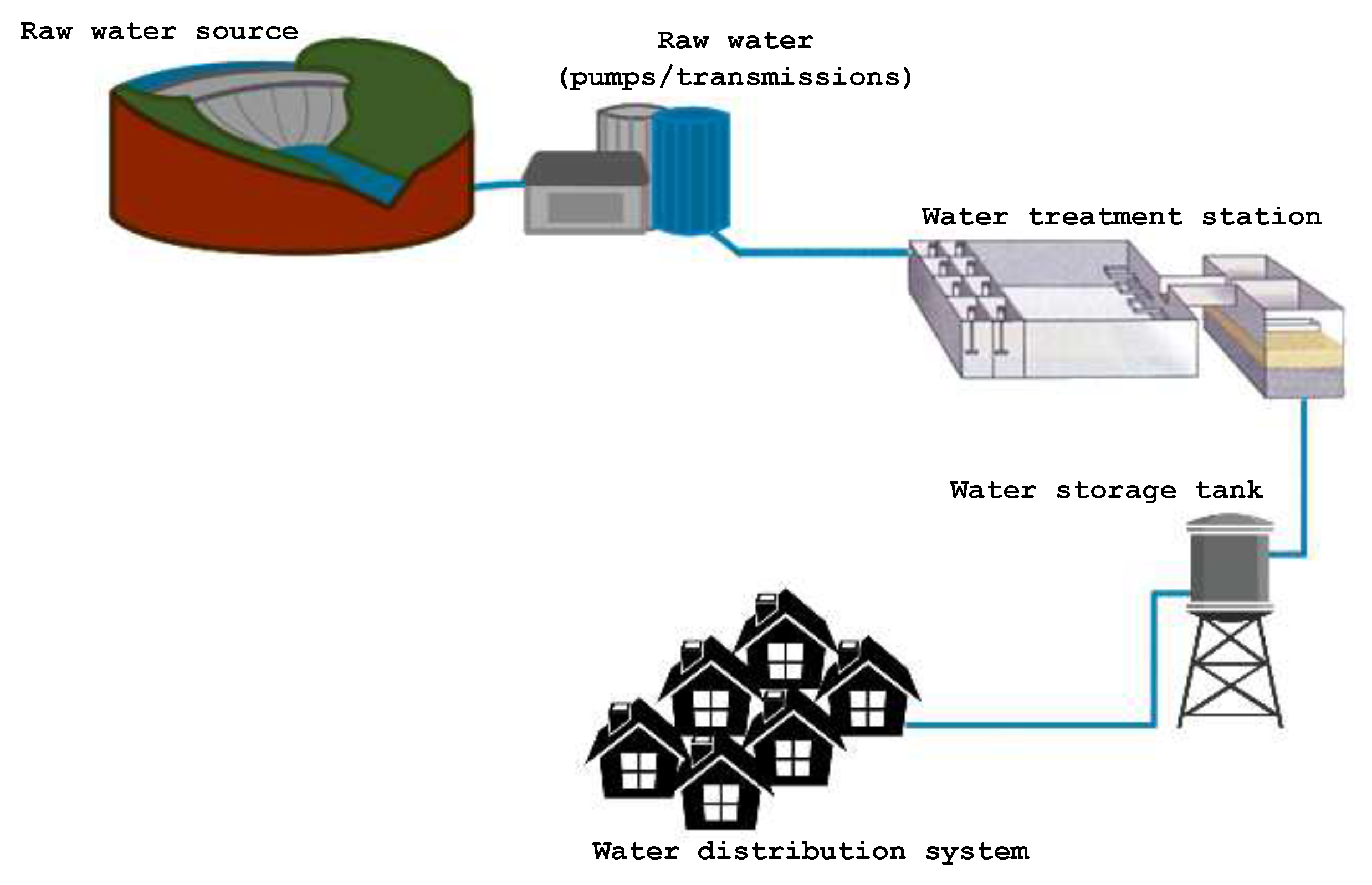
The term water supply system denotes a set of interconnected hydraulic components to collect water from rivers and lakes, to apply water treatment procedures, and to distribute water to the final consumers [
1]. A conventional water supply system includes the following elements:
Raw water source: water found in the environment.
Raw water pumps: a set of equipment and installations used to collect water from rivers and lakes.
Raw water transmissions: transportation raw water to the water treatment facilities.
Water treatment station: infrastructure for water purification installed close to the final delivery points, to reduce pumping costs and to reduce the chance of new contamination after treatment.
Water storage tank: a water tank installed on top of a structure, at a height sufficient to pressurize the water distribution system.
Water distribution system: a set of interconnected pipes and valves used to deliver water to the eventual consumers.
Figure 5 shows the water life cycle of a water supply system.
4.3. Complex Event Processing
Complex Event Processing (CEP) is a technology for capturing and analyzing event streams in order to identify patterns of behavior in real-time [
20]. CEP plays an important role in many application areas, such as smart metering, energy management, and irrigation for agriculture [
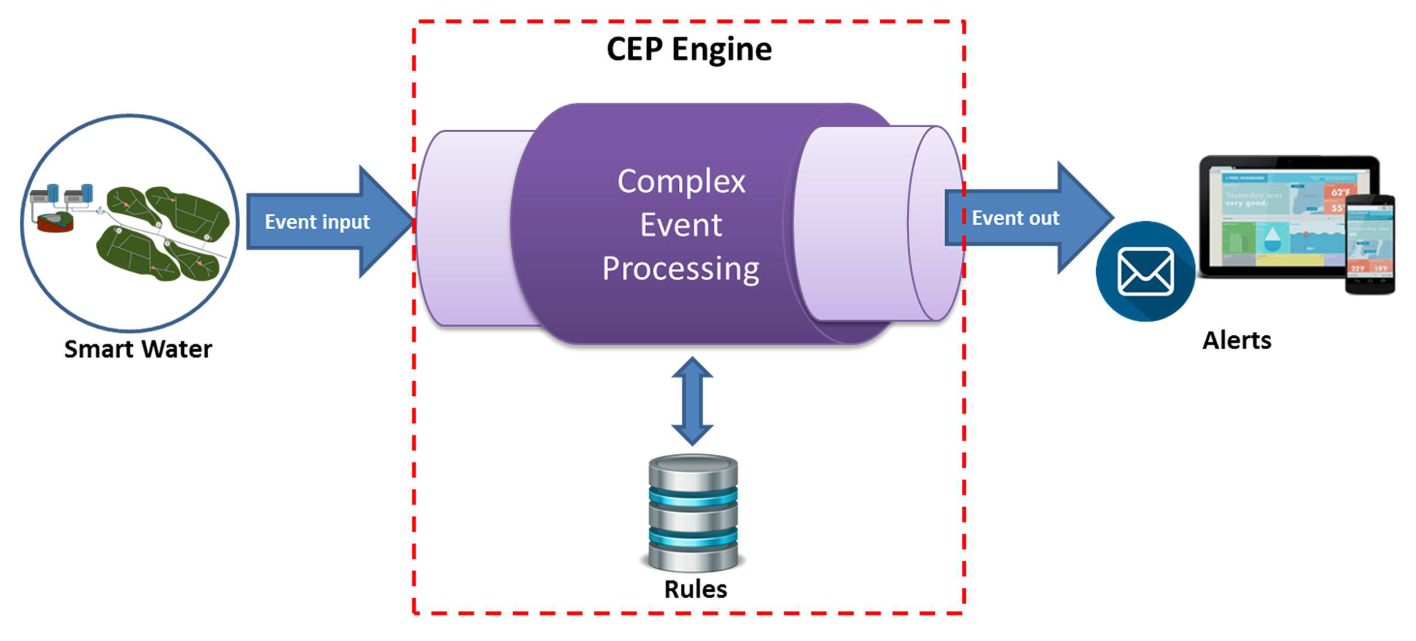
21]. In the context of water management systems, one could use CEP to measure pressure and volume of water flow in pipes, to identify patterns of water leakage, anticipate accidents. A set of CEP rules specifies each pattern. A rule defines filtering, aggregation, correlation, and transformation of data flows.
Figure 6 illustrates the CEP architecture. The CEP engine receives the event streams and applies the CEP rules to identify predefined patterns. As soon as a pattern is recognized, the CEP engine sends an alert to notify human operators or other systems.
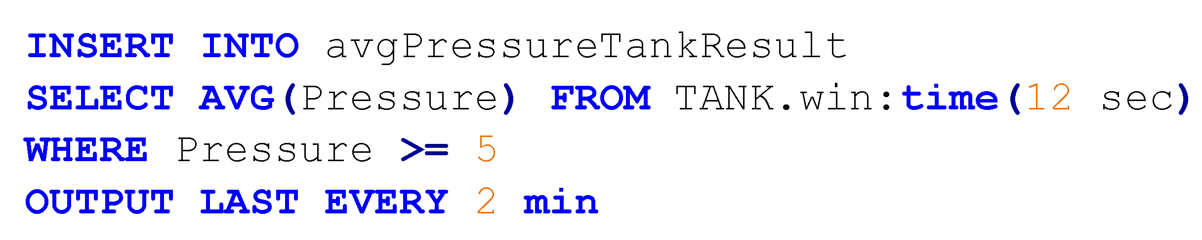
CEP rules are queries to perform filtering, aggregation, correlation, and transformation of data flows. This work adopts Event Processing Language (EPL) to specify CEP rules. In this work, each CEP rule defines an existing water management policy. For instance, the rule in
Figure 7 checks every 2 min if the average pressure in 12 s is higher than a critical limit. In addition to the water management rules, this work uses CEP rules to identify undesirable situations, such as rapid reduction of the water level in the water storage tank, or critical level of water (too high or too low), and send an alert to water managers to report the pattern.
5. Material and Methods
This section presents the REFlex Water methodology and architecture for smart water management, which is illustrated in
Figure 8 and
Figure 9.
Figure 8 provides an overview of the methodology, namely: (i) problem understanding, corresponds to the study and understanding of the problem to be analyzed, the identification of the components of the water system, discussed in
Section 4.2; (ii) architecture definition and framework creation, we discuss in the remainder of this section; and (iii) scenario definition and evaluation, explained in
Section 6.
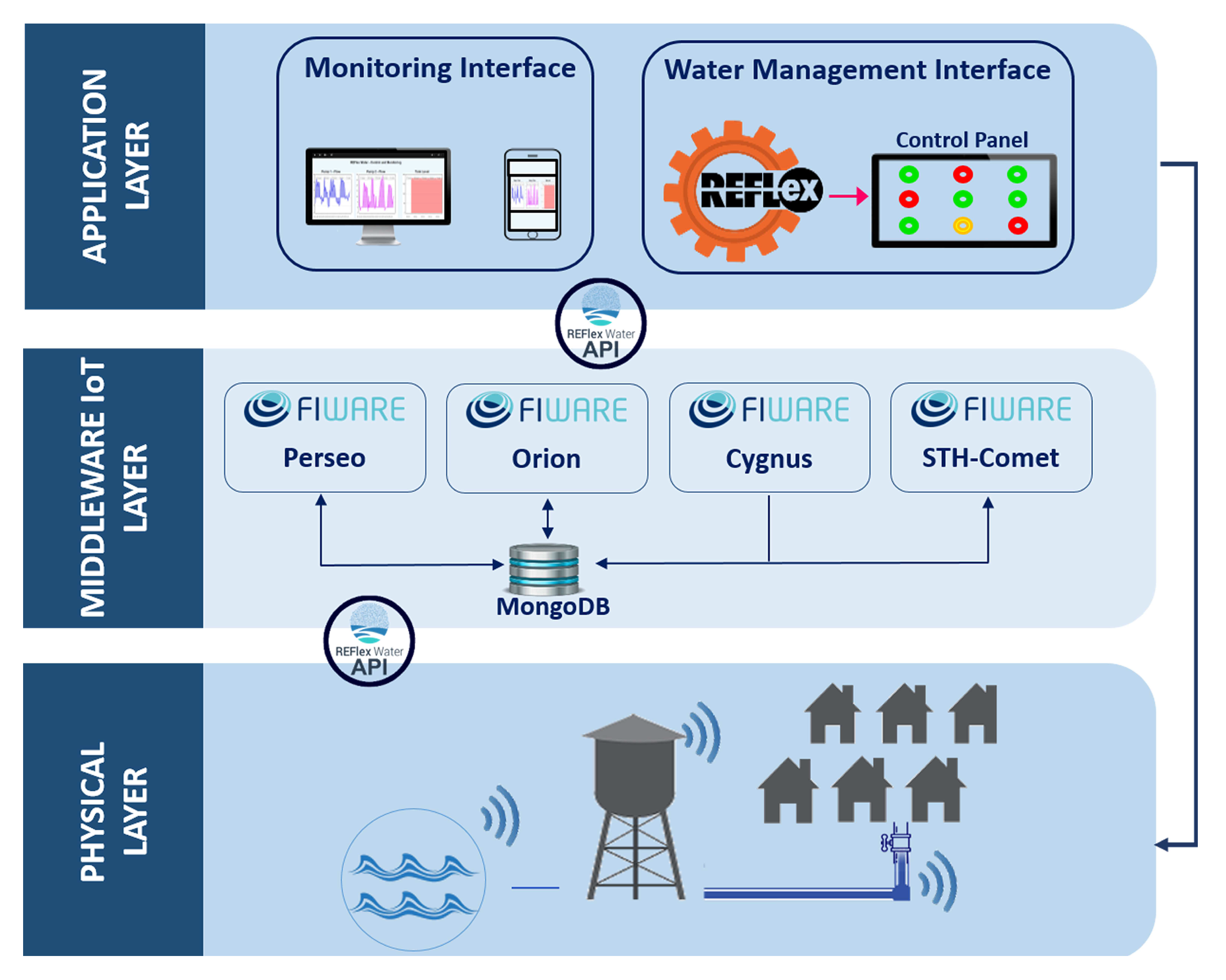
The architecture splits up the water management system into three layers (
Figure 9):
5.1. Physical Layer
All components of the water supply system, including raw water sources, raw water pump, raw water transmission pipes, water treatment stations, water storage tank, and the water distribution system, are in this layer. It also contains water meters, IoT devices to measure pressure in the pipes and volume in the water storage tank, actuators. It connects the network of sensors and actuators to a gateway. One can use Raspberry Pi, ZigBee, Arduino to implement the gateway. This layer offers an API to program the engine that packages all the data collected into a JSON message and sends it to the Middleware IoT Layer JSON. Each message has a NODE_ID and a PAYLOAD:
NODE_ID: identifies the monitored entity (e.g., water storage tank).
PAYLOAD: identifies the sensor (TAG_SENSOR), the data collected (VALUE_SENSOR), and the timestamp data (TIMESTAMP_SENSOR).
5.2. Middleware IoT Layer
This provides services for storage, analysis, processing, and orchestrating the communication between the Physical and Application layers and among the sensors and actuators in the IoT infrastructure. The implementation uses the open-source FIWARE platform, which offers a rich set of APIs (The algorithms and APIs used to create the Framework is available at
https://github.com/telefonicaid) [
22] for the development of smart applications [
23]. This layer has three main components:
Orion Context Broker: it receives data from sensors in the IoT infrastructure; the CEP engine processes the data; as soon as the CEP engine recognizes a pattern of interest, it notifies the Orion, which updates the monitoring interface in the Application layer; Orion uses Cygnus to keep historical data persistent.
Perseo: whenever an IoT agent produces an event, the Perseo-CEP processes the event, applying predefined rules to identify a pattern of interest. As soon as the Perseo-CEP identifies a patter, it notifies the system operator sitting in the Application layer. For instance, every 2 min the CEP rule in
Figure 7 checks if the average pressure in 12 s is greater than the critical limit. It recognizes the pattern when the condition is true. Then, it emits an alert message, which is placed in the message queue to be consumed by registered consumers in the Application layer.
Cygnus: is responsible for maintaining the historical data managed by the Orion Context Broker over time. Historical data maintained by Cygnus are useful for analyzing trends, for instance.
STH-Comet: retrieves historical data from the system and updates trend graphs the monitoring interface in the Application layer.
MongoDB: this component records all data collected in the Physical layer. It also controls the access to this information, offering homogeneous access to data.
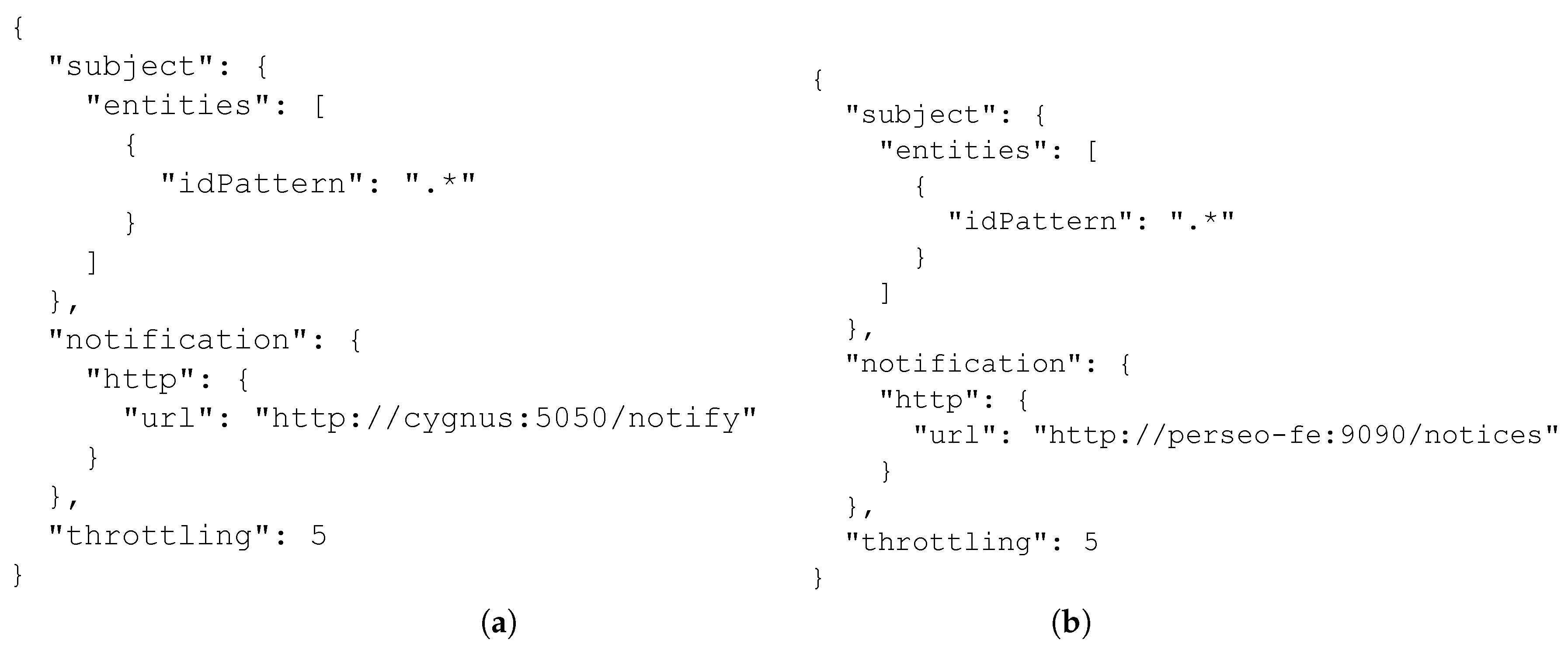
The Orion Context Broker’s Publish/Subscribe allows the connection between the FIWARE components. Each FIWARE component signs up the Orion Context Broker to receive a notification whenever a sensor sends some data.
Figure 10 shows two JSON files with the signature of two components: Cygnus (
Figure 10a) and Perseo (
Figure 10b).
Table 2 details each field in the JSON file. The component must execute the command POST /v2/subscriptions to save the signatures to the FIWARE database (MongoDB [
24]). In addition to the signatures, the MongoDB component records the CEP rules and the data collected by the sensors. The STH-Comet accesses the MongoDB to generate the information displayed by the monitoring and control graphics.
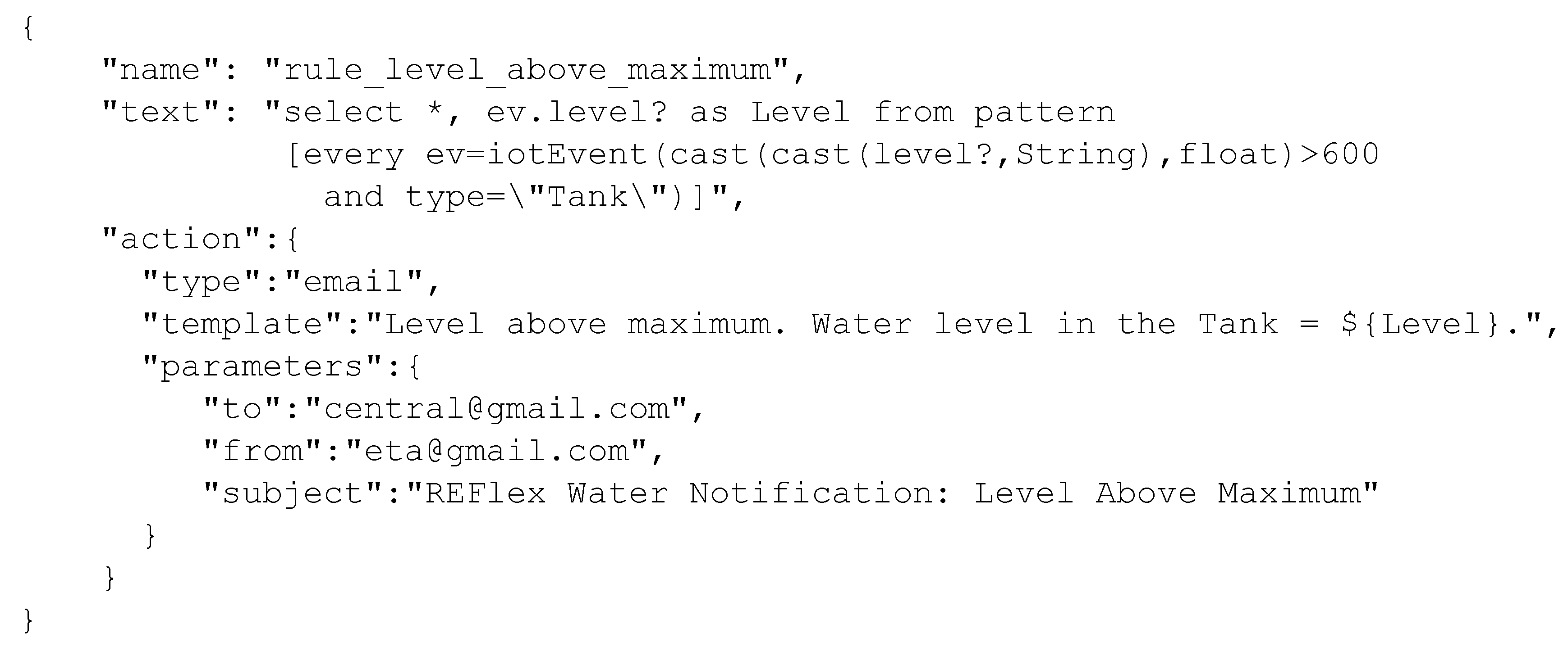
Figure 11 shows a JSON code with a rule created in Perseo.
Table 3 details the code.
5.3. Application Layer
The architecture allows for the development of different applications, including dashboards of performance indicators, web/mobile applications to management of the water supply system. Moreover, in this layer, the REFlex rule engine interprets the declarative business process specifying the water management policies to control the system operations. The control panel shows all tasks enabled and prohibited at a given moment. As soon as the operator executes an activity (e.g., turning on a pump), the configuration of enabled and prohibited tasks changes in the control panel: thus, the operator is free to choose what task to execute in the next step as soon as he or she respects the management policies.
It is important to emphasize that REFlex Water architecture can be adapted to work with other smart city systems. Given an infrastructure for the physical layer, one should specify the declarative business process to describe the management policies for the new smart system. However, it requires no modification to the REFlex architecture.
6. Results and Discussion
This section evaluates the REFlex Water architecture, a solution for intelligent water management that uses IoT, Complex Event Processing, and declarative processes. The evaluation demonstrates the practical use of REFlex Water through a real water distribution system installed in a Brazilian city. Additionally, the section discusses the advantages of declarative business processes in the context of water distribution systems, whose behavior is usually difficult to foresee.
Traditional workflow management systems that use imperative process modeling language (e.g., BPMN) are useful for modeling static and standardized systems. However, they do not provide an adequate response when dealing with dynamic and chaotic processes (e.g., healthcare, disaster prevention, and water systems) [
25].
The management of water supply systems requires a team of professionals with different skills and levels of experience. Such professionals need to adapt to unexpected situations that may occur in this scenario [
17,
18,
26]. In this context, declarative processes may offer the required flexibility, and maintain control over water management policies [
26].
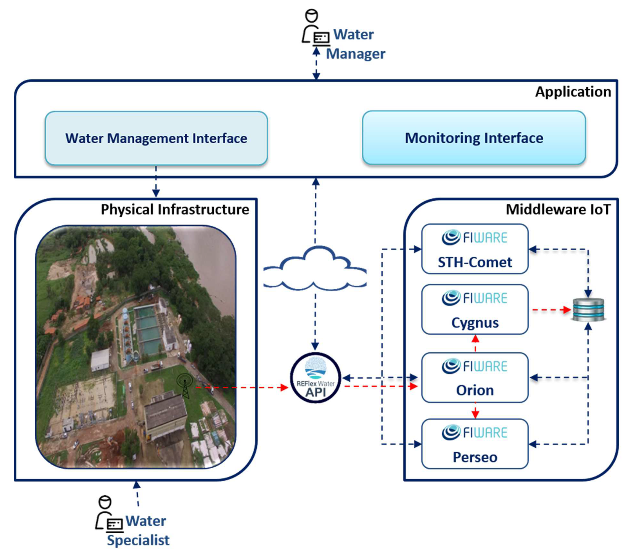
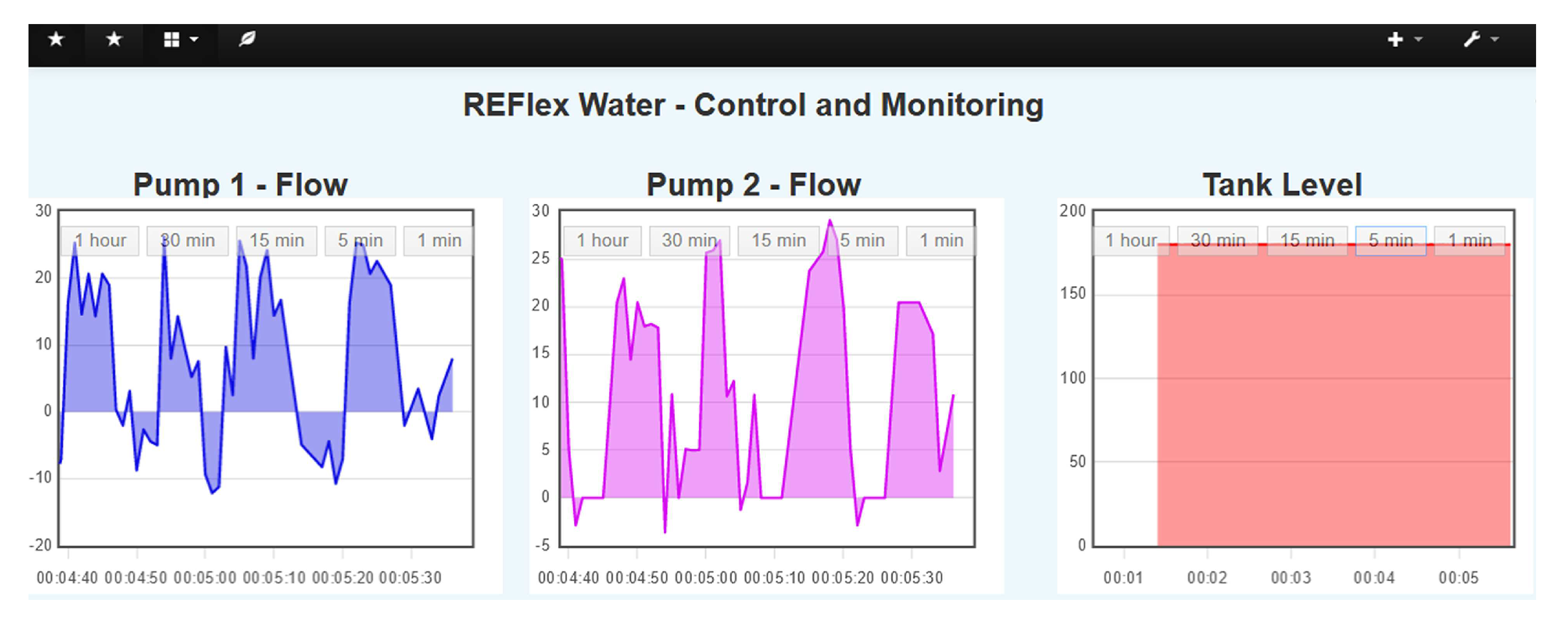
Figure 12 illustrates a scenario to demonstrate the practical use of the REFlex Water framework. Notice the presence of water specialists at the Infrastructure level and Water managers at the Application level. The REFlex Water API acts as a gateway receiving data from sensors and forwarding it to Orion FIWARE, which in turn sends it to a CEP server that processes and analyzes the data. Afterwards, the Orion FIWARE and STH-Comet updates the monitoring interface (
Figure 13) used by water managers to visualize the current time series data stored by Cygnus.
Table 5 shows the data that updates the monitoring interface (
Figure 13) and displays the time series.
The paper includes a set of algorithms to explain the dynamics used in the schema in
Figure 12:
Algorithm 1: Orion checks the sensors for new data. When a sensor reads the data, it sends it to Orion informing the identifier of the monitored item (e.g., Tank-1) and the payload.
Algorithm 2: When Orion receives the data from the sensors, it checks for Cygnus signatures: if any, Orion forwards the data to Cygnus, which records the information in the MongoDB component. Orion executes the same process on the Perseo component signature. Such verifications are required because the FIWARE records historical data and CEP analysis only for subscriber components.
Algorithm 3: After Cygnus receives Orion’s data, it saves it in the MongoDB component.
Algorithm 4: Perseo records the data, and checks if there are any rules associated with that data. if so, and if the rule is valid, it applies the rule seeking to identify a pattern. When it recognizes a pattern, it triggers an alert.
| Algorithm 1: Sending data from sensors |
 |
| Algorithm 2: Orion Receiving data from sensors |
 |
| Algorithm 3: Storage in Database by Cygnus |
Result: Storage in Database
System initialized;
Data received by Orion;
save(); |
| Algorithm 4: Processing, analyzing and sending alerts |
 |
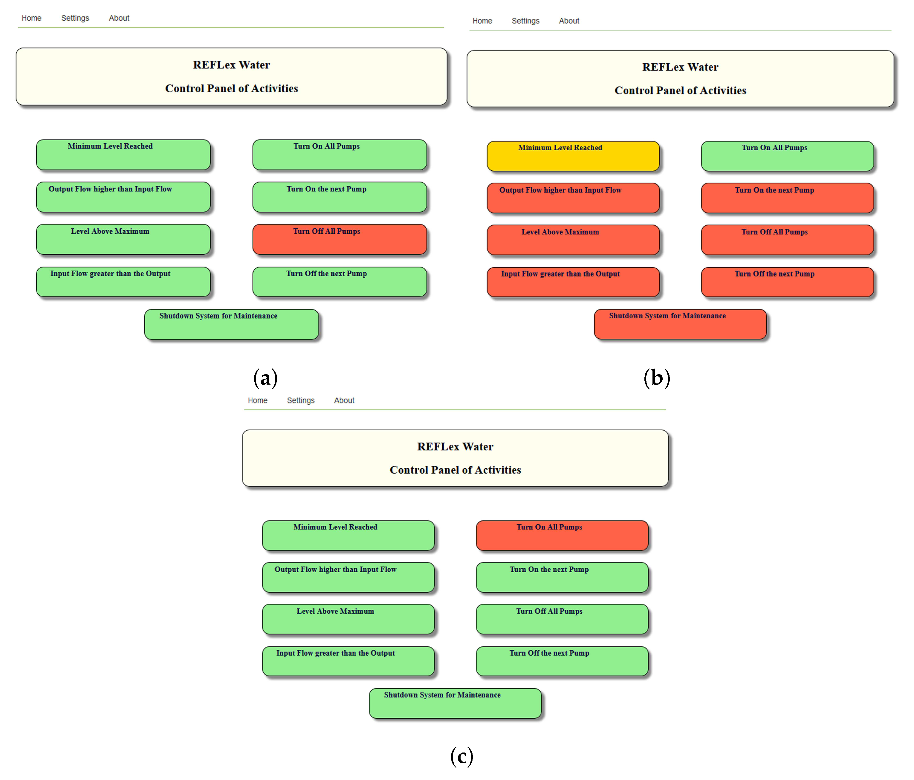
Figure 14 presents the management panel generated from the declarative model described in
Figure 15. Each box represents a process’s activity. A green box identifies an activity enabled in a given moment. Yellow boxes are activities temporarily disabled. Additionally, red boxes are disabled activities. As the process executes the activities, the panel configuration changes. For instance,
Figure 14a–c show three different configurations for the management panel.
To illustrate the impact that changes in the water management policies can have on the process model, assume the imperative model in
Figure 16a. To include a maintenance rule (see the blue area of
Figure 16b), one needs to add fifteen new components to the original model. On the other hand, to make the same modification to the declarative model (
Figure 15), only one new element is required. It happens because the declarative model does not specify when an activity must be executed, as occurs in the imperative model. For instance, both the processes have an activity named “Turn On All Pumps”. The imperative process enables it in certain specific situations, whereas the declarative process allows execution of the activity in all states. Therefore, although the activity Turn On All Pumps participates in the new rule, the designer does not mention it in the process update.
7. Conclusions
This paper presents an architecture for intelligent water management, called REFlex Water, which adopts the Internet of Things (IoT), Complex Event Processing (CEP) technology, and declarative business processes to control the operational activities of water supply systems.
The paper has demonstrated that the combination of these technologies is a powerful tool in the context of water systems management: IoT devices represent an efficient and low-cost solution for continuous monitoring and controlling many aspects of water distribution in real-time; declarative business process languages provide the rigor and flexibility required to specify systems whose behavior is difficult to foresee (e.g., water distribution systems); Complex Event Processing (CEP) technology can handle large data streams produced by the IoT sensors; moreover, CEP languages can express all rules defined in a declarative business process language (e.g., DECLARE).
The paper has described the implementation of REFlex Water using FIWARE platform, which provides a rich set of APIs for the development of smart city applications. It has also demonstrated a practical application of REFlex Water through an example of a real water distribution system installed in a Brazilian city. To the best of our knowledge, this is the first work to use IoT, CEP, and declarative business process technologies to manage water distribution systems in real-time. After validating the REFlex technology, the authors are cooperating with the Brazilian water company to establish REFlex Water in other sectors of the water distribution system.


