1. Introduction
Most protection installed in China 10 kV distribution networks is mainly based on the simple three stage overcurrent protection. As more and more distributed new energy sources are connected to the distribution networks, the conventional radial distribution network is becoming an active distribution network. It has the characteristics of multi-source, multi-branch, bidirectional power and fault current flow, as well as weak infeed. It is very difficult or impossible to apply the conventional overcurrent protection in the distribution networks with distributed generations, so adaptive overcurrent protection has been developed for distributed generation [
1,
2,
3,
4]. As this type of protection is still basically an overcurrent protection, it is very difficult to provide a sensitive, fully satisfactory protection for distribution networks with distributed generations under all operation conditions. Therefore, current differential protection has been considered for application in distribution networks with distributed generations [
5,
6,
7,
8,
9]. Compared with the traditional overcurrent protection, the principle of line current differential protection is simple. As it is a unit protection, the protection zone is defined, it does not require time grading. Its protection performance is also not affected by distributed generation connected in the distribution networks. It can be applied for fast main protection or fault location in the distribution networks. Current differential protection requires reliable communication. With the development of 4G LTE (Long-Term Evolution) wireless communication, it is possible to apply the current differential current protection using the 4G LTE wireless communication in the distribution networks.
In recent years, research has been carried out on the application of current differential protection for distribution networks with distributed generations. Reference [
5] analyzed the protection problem of distributed energy resources (DER) access to distribution network and proposed a differential protection scheme for active distribution network. The scheme uses centralized line differential protection and decentralized bus differential protection. DTU (Distribution Terminal Unit) uses built-in Ethernet port technology and dedicated fiber-optic communication channels for data transmission and simultaneous sampling. Reference [
6] proposed a unit-type protection scheme that utilizes the principle of differential current protection in urban distribution networks. Multifunction line differential relays provide basic in-zone unit protection, local and remote standby overcurrent protection, and dedicated ground fault protection for downstream power systems to improve line-to-ground fault sensitivity. Reference [
7] proposed a current differential protection scheme which uses positive-sequence fault component for the protection. Reference [
8] proposed a pilot protection scheme which compares the phase angle variation of positive-sequence fault current; this scheme only needs to transmit numerical value of phase variation, therefore, communication channel of high synchronization is not required. Reference [
9] derived a differential criterion of current amplitude; the criterion just needs current amplitude information without strict synchronization of data sampling. Reference [
10] proposed an integrated protection and control system for 10 kV feeder applications based on PTN (Packet Transport Network) communication. The system uses centralized line differential protection and decentralized bus differential protection. It can be seen from these publications that these current differential protections for application in distribution networks cannot adaptively change their settings automatically if the topology of the primary distribution networks change. As the topology of primary distribution networks can change frequently, particularly in China, due to fast development of its distribution networks, this paper derived a method of automatically changing the setting of current differential protection when the topology of primary distribution networks changes.
Feeder automation technology is an important mean to improve the standard of fault handling in distribution networks. At present, various types of feeder automation have been used, including voltage–time type [
11], closing quick-break type [
12], intelligent distribution type, and centralized type [
13]. These types are all aimed at the faults with large fault current. To solve the problem existed in the voltage–time feeder automation that the fault processing time is long, the upstream switches of the fault point need to tolerate fault current twice, and the upstream sections need to experience two short-time power outages, [
14] proposed a quick fault location and isolation method for distribution network based on adaptive reclosure. However, none of these methods can really provide a fast, sensitive fault location function. They have no adaptive auto-switching function which can automatically change its switching procedure if the topology of the primary distribution networks changes.
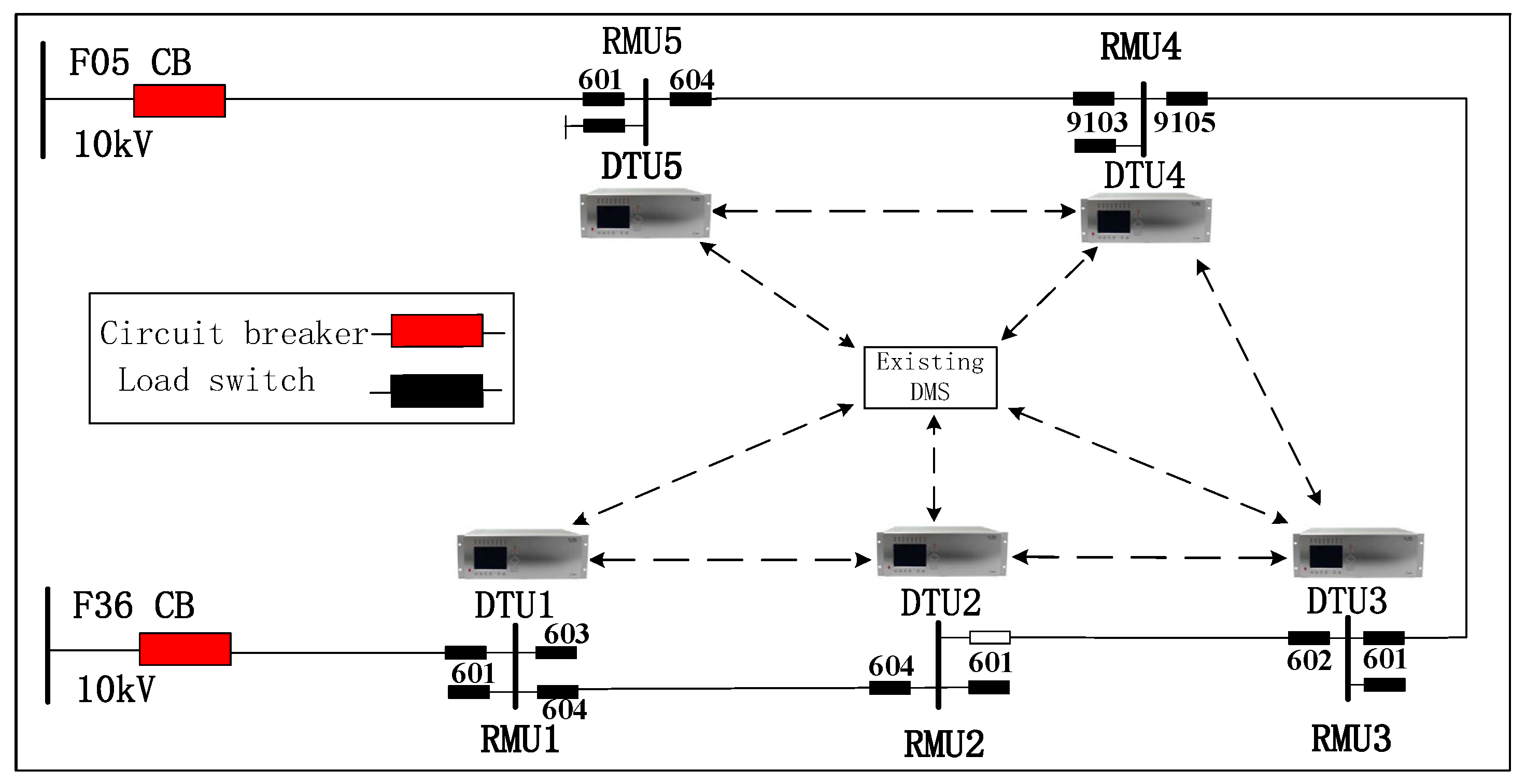
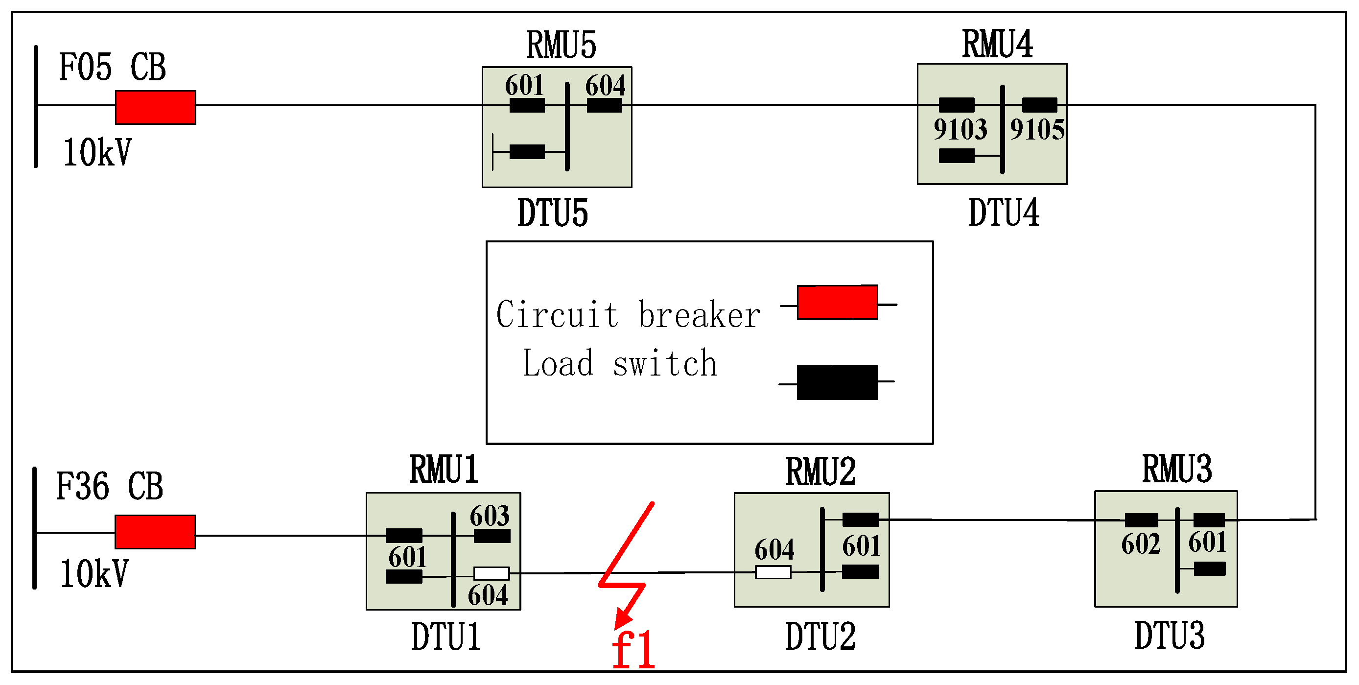
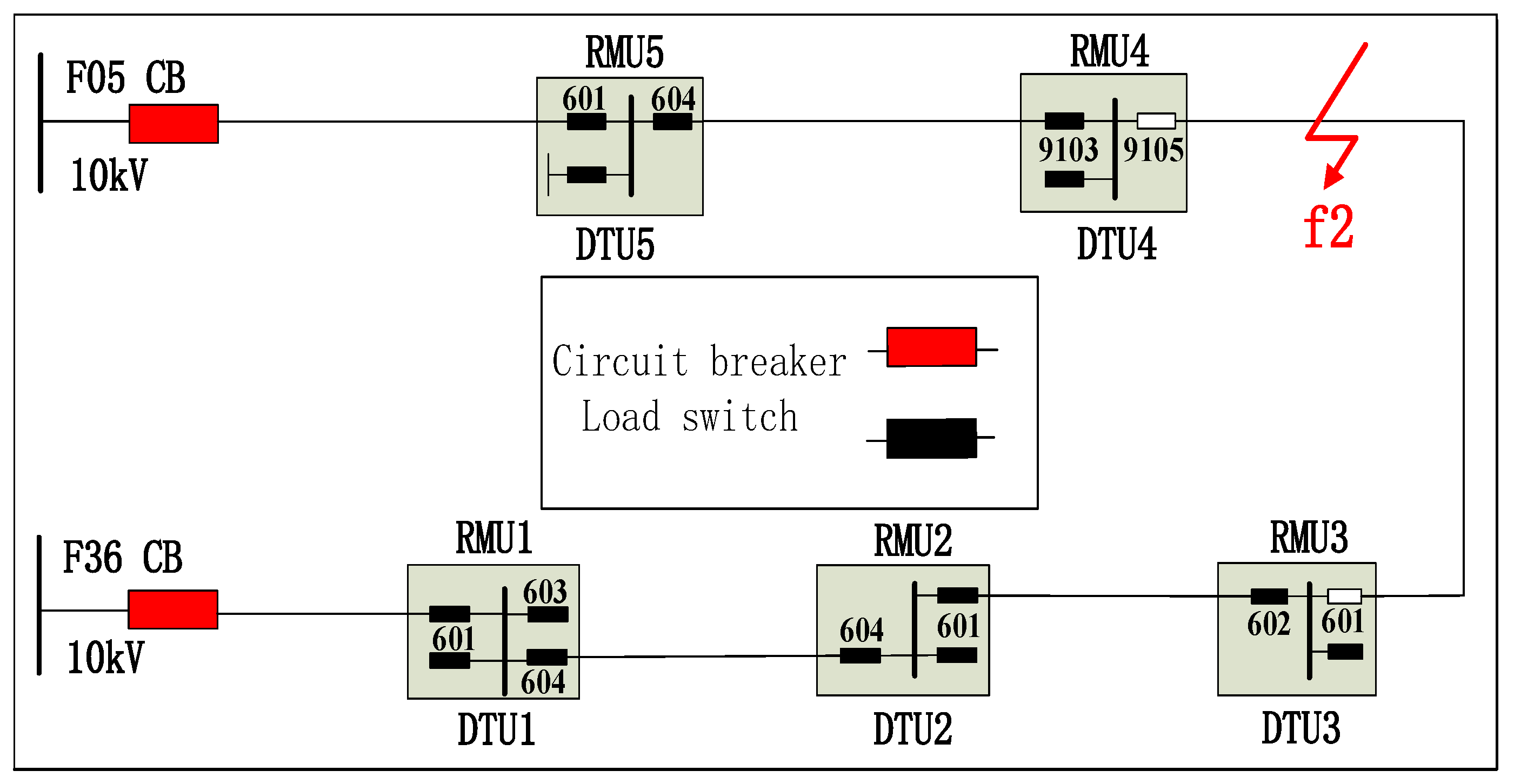
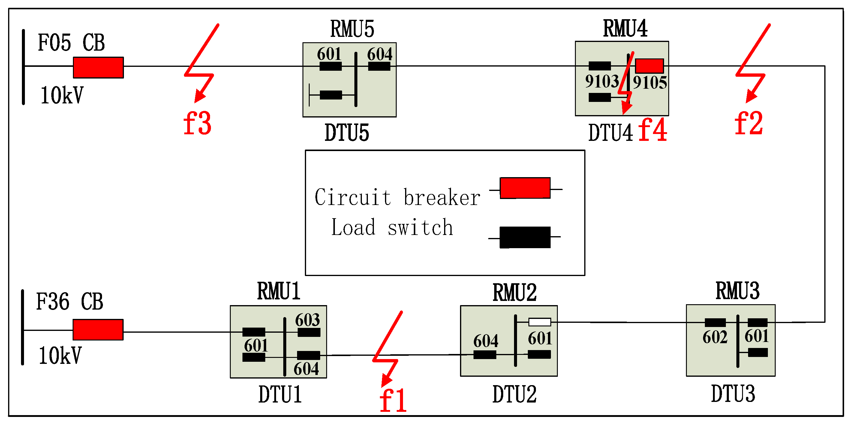
In the 10 kV distribution networks in China Southern Power Grid, normally circuit breakers are only installed on the outgoing feeders at the 10 kV substations, and load switches with DTU are installed on the ring main unit, as shown in
Figure 1. As the load switch is only capable of breaking load current, when a power system fault occurs, the circuit breakers at the 10 kV substation will operate first to break the fault current. After the fault is located, then the load switches which are the nearest to the fault location will open to isolate the fault. After the fault is isolated, the circuit breakers at the 10 kV substation will re-close to restore the power supply to the healthy part of the network. For the traditional automation system, as there is no fast fault location function, after a power system fault is cleared, it takes minutes or even hours to manually locate a fault and isolate a fault; the restoration process is slow after a feeder is tripped out when a power system fault occurs. Therefore, it becomes necessary to find a quick fault location method and automatic closing strategy to restore power supplies to customers after a power system fault. As current differential protection is a unit protection, it can be easily applied for fault location.
This paper presents an adaptive current differential protection and a fast auto-closing system developed for the 10 kV distribution networks in China Southern Power Grid. The current differential protection can adaptively change its settings according to the topology change of the primary distribution networks, thus the system effectively reduces the operation and maintenance cost of the power distribution network. As load switches are installed on the 10 kV feeder, the current differential protection function is used for fault location. The fast auto-closing function is implemented in the existing DMS (Distribution Management System). When a fault occurs on the 10 kV feeder, the current differential protection can locate the fault quickly and accurately, and the fault can be isolated quickly. After the fault is isolated, the auto-switching function in the DMS can quickly restore the power supply to the healthy part of 10 kV feeder in less than one second.
2. System Architecture and Communication
2.1. System Architecture
The integrated protection and control system developed has been installed on a 10 kV feeder in China Southern Power Grid, as shown in
Figure 1. The feeder is connected to two 110 kV/10 kV substations by CB F05 and F36, respectively. The feeder is normally run in open-ring configuration, that is, the normal open point of the 10 kV feeder is at 601 of RMU2 (Ring Main Unit 2). DTU is installed at two 110 kV/10 kV substations and each 10 kV Ring Main Unit (RMU). Each DTU communicates with the adjacent DTUs for current differential protection function, also communicating with the existing central DMS (Distribution Management System) for SCADA (Supervisory Control And Data Acquisition) function and auto-switching function to restore power supplies after a power system fault is cleared.
The adaptive current differential protection function is located in each DTU at each RMU. The protection communicates with adjacent DTU to obtain the current data from remote terminals. If the topology of the feeder changes, the DMS can detect the change and send the information to the affected DTUs. The current differential protection then changes its configuration settings according to the new topology. The DMS is responsible for modeling, real-time monitoring, and clock synchronization of the entire distribution network, and for performing topology dynamic analysis on the entire distribution network, transmitting topology change data to each DTU terminal. The DTU is responsible for transmitting the respective sampled data and trip information to adjacent terminals, collecting the sampling data and operation information of adjacent terminals, and responding quickly to a power system fault by running its differential protection algorithm. The protection is fast and can dynamically adapt to topology change of distribution networks.
2.2. Communication
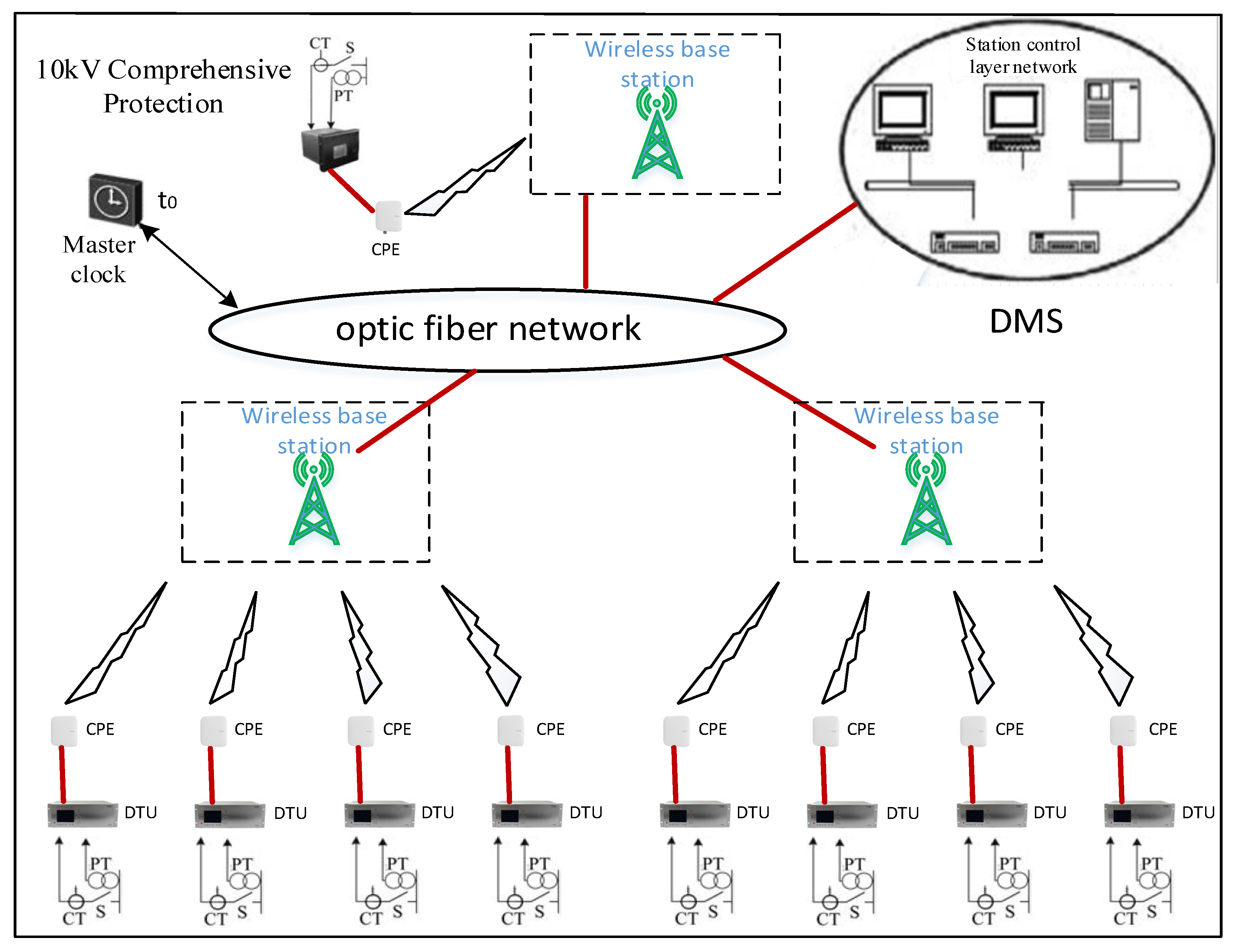
Fiber network is normally available in urban areas, but it is not readily available in remote rural areas. Due to the rapid development of 4G wireless communication, it is considered for the application of the protection and control system. Special CPE (Customer Premise Equipment) of the wireless communication equipment has been developed for current differential protection with accurate time synchronization. The IRIG B signal from the CPE is used for synchronization of the differential protection.
The DMS and DTUs are connected by setting up a 4G wireless private network, as shown in
Figure 2. A CPE device is connected to each DTU for wireless communication. Communication networks also use data encryption to ensure data reliability and integrity.
The distribution master station transmits the distribution system model data and terminal deployment information to the DMS through TCP (Transmission Control Protocol). Through 4G wireless private network, the DMS uses Web Service to exchange topology change information with DTU terminals, and to enable or disable the current differential protection function. The 4G wireless private communication network is used between the DMS and the terminal, and a discovery/registration mechanism is used between the DMS master station and the terminal, that is, after the terminal is deployed, the terminal is registered in the DMS through a Web Service registration service, and the terminal model information is transmitted through a file transmission service. After successfully registering with the master station, the terminal real-time data is transmitted through IEC 60870-5-104 protocol to the DMS. At the same time, IEEE 1588 protocol is adopted to perform time synchronization service for the terminal. Communication between terminals is also through the wireless private network, but because of the need to transmit sampling values and trip signals, GOOSE/SV protocol based on subscription/publishing mechanism is required to ensure the synchronization efficiency of sampled values.
2.3. Clock Synchronization Technology
The terminal’s clock synchronization uses the IEEE 1588 timing method. IEEE 1588 is an Ethernet synchronous clock that provides sub-microsecond timing accuracy. IEEE 1588 uses the Best Master Clock algorithm to determine the most accurate clock in the network to be the Master. All the remaining clocks are used as slaves, synchronized with the master clock. In the adaptive differential protection, since the sampling information and the trip information need to be transmitted, and the timing accuracy is required to be very high, the IEEE 1588 dedicated timing chip is deployed inside the terminal, that is, the timing information is processed at the MAC layer to ensure the required timing accuracy. In the application, the international common time format code is used to combine the timing of the timing pulse with the time data of the serial message to transmit time information. After CPE receives the time information, it converts to IRIG-B code with timing pulse. DTU then uses on-time edge of the timing pulse to synchronize the sampling of the currents data and perform current differential protection calculation. The accuracy of the time synchronization was tested in the factory, and the test results are shown in
Table 1.
3. Topology Adaptive Differential Protection
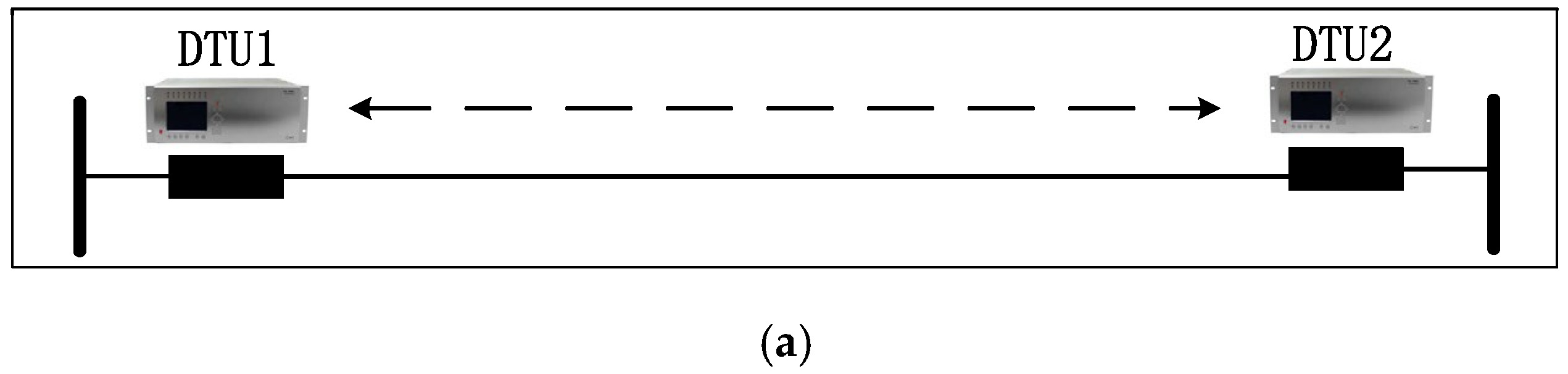
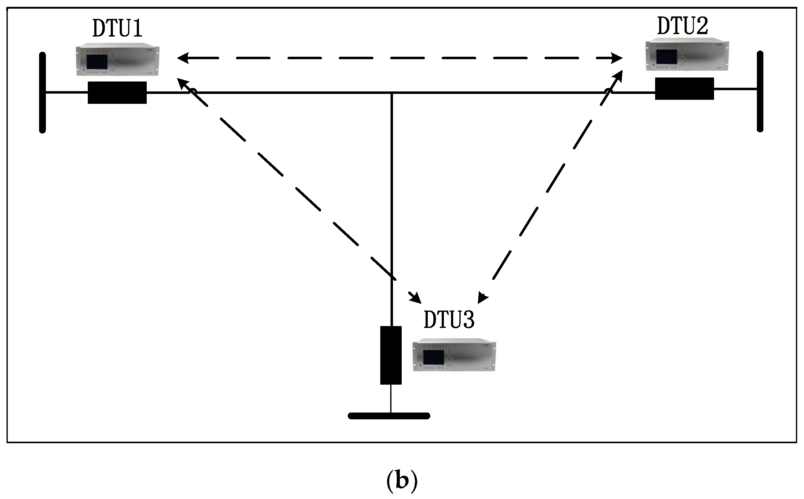
The adaptive current differential protection developed in the paper can automatically change its configuration settings if a change of the topology of the 10 kV distribution networks is detected. For example, if a new T-line is added to a feeder, the two-terminal feeder becomes a three-terminal line, as shown in
Figure 3b. Before the topology change, the DTU1 communicates with DTU2 for its current differential protection function, as shown in
Figure 3a. After the topology change from a two-terminal circuit to a three-terminal circuit, DTU1 not only needs to communicate with DTU2, but also needs to communicate with DTU3 for its current differential protection, this requires change the configuration settings of current differential protection in the DTUs. For traditional differential protection, the settings are normally changed manually, but it is time-consuming to do it manually.
Another scenario of changing the topology of the primary circuit could be removing or adding substations. For example, if RMU2 shown in
Figure 1 is removed, DTU1 then needs to communicate with DTU3 for its current differential protection instead of DTU2. This requires changing of the configuration settings of current differential protection to reflect the change of the topology of the primary circuit. Traditionally, the settings are changed manually. In this paper, an adaptive function of the automatic changing of the setting is developed. After the topology change, the DMS knows the topology change from the information obtained by it, and then it automatically sends the new configuration settings of the differential protection to the affected DTU. Therefore, manually changing the settings of the current differential protection is not required, and this saves outage time for system operations.
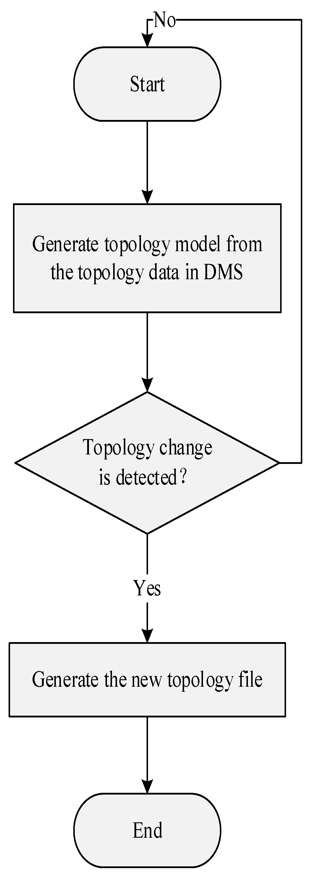
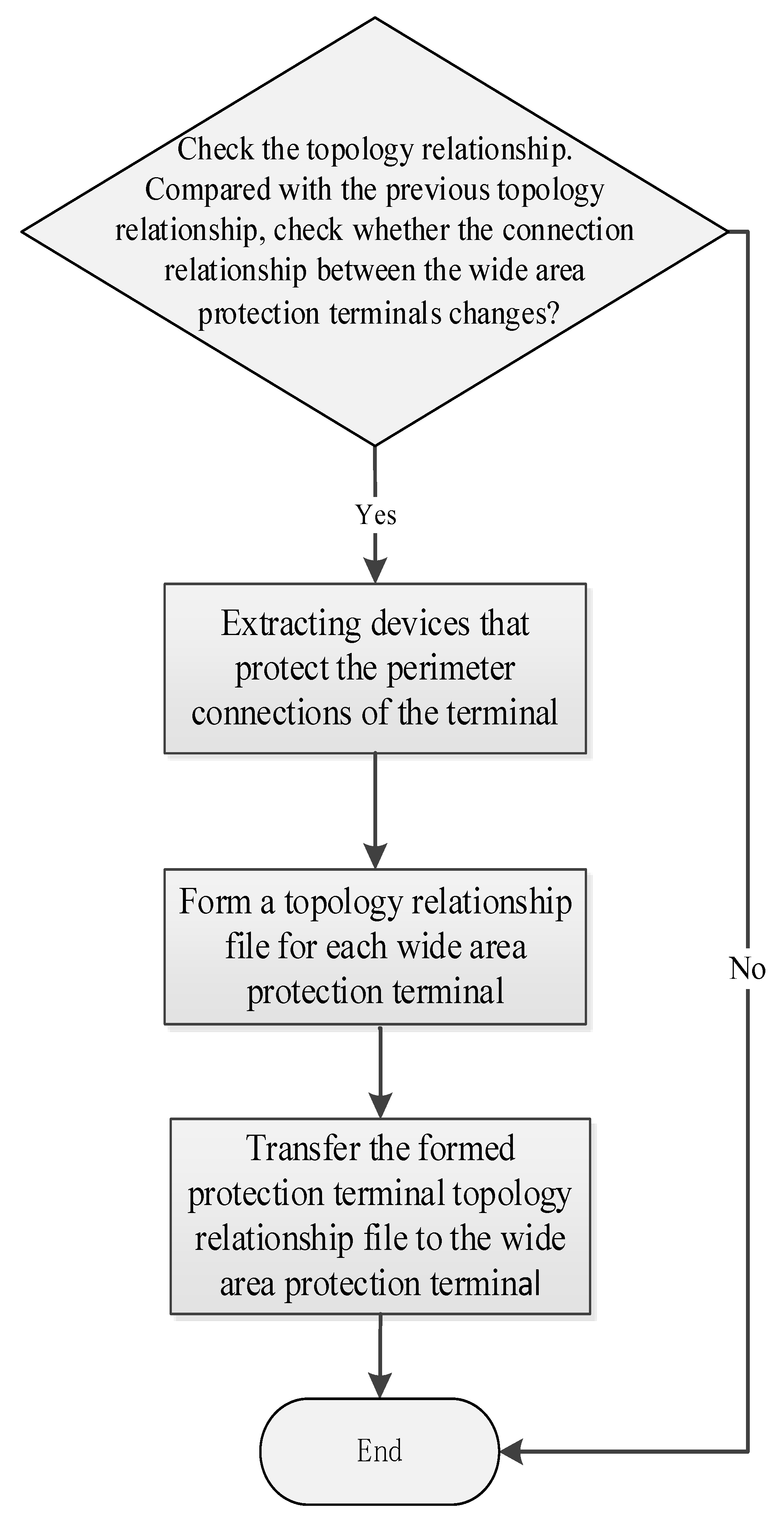
3.1. Topology Adaptive Technology
Figure 4 and
Figure 5 show the flow charts of the process of obtaining the change of the topology of the distribution network and the process making the change of differential protection setting.
The operation procedure for the user is as follows:
- (1)
When the site is ready for construction to carry out feeder modification, the control engineer in the control room first switches off the feeder, then issues a command to block the protection function associated with the feeder.
- (2)
After the feeder is isolated and earthed, construction work then starts.
- (3)
The feeder is then ready for switching on after the construction is completed.
- (4)
The control engineer then issues command to send new topology information to the affected DTUs through DMS system.
- (5)
After DTU receives the new topology information, the differential protection then changes its configuration settings to suit the new topology of the feeder. The control engineer then issues command to enable the differential protection, the feeder is then ready to be switched on.
3.2. Distributed Current Differential Protection Technology
The current differential protection function is located in each DTU. Each DTU communicates with adjacent DTUs to perform the current differential protection function.
The algorithm of the current differential protection is as follows, that is, the differential current and restraint current are calculated as follow:
In the above formula, is the sum of all sides phase currents; is the largest phase current in all sides; is the sum of the phase currents on the other sides (except the maximum phase current side).
The protection operating characteristic is shown in
Figure 6. In the Figure, Icd is the setting of the differential current protection.
3.3. Zero Sequence Current Differential Protection
The 10 kV distribution network in the urban area normally adopts the neutral grounding through small-resistance grounding method. The CTs in the RMU are normally installed on phase A, phase C, and a CT around all three phases (i.e., summation of all three phases to obtain the zero-phase sequence current). The ratio of the zero-phase sequence CT is smaller than the CT ratio of the phase A and C, so the current differential protection of the zero-phase sequence current provides sensitive differential protection for ground faults.


