Article

Distributed Edge Computing to Assist Ultra-Low-Latency VANET Applications

by
Andrei Vladyko
1,*,
Abdukodir Khakimov
2,
Ammar Muthanna
2,3,
Abdelhamied A. Ateya
2,4 and
Andrey Koucheryavy
2
1
R&D Department, The Bonch-Bruevich Saint-Petersburg State University of Telecommunications, 193232 Saint Petersburg, Russia
2
Department of Telecommunication Networks and Data Transmission, The Bonch-Bruevich Saint-Petersburg State University of Telecommunications, 193232 Saint Petersburg, Russia
3
Department of Applied Probability and Informatics, Peoples’ Friendship University of Russia (RUDN University), 117198 Moscow, Russia
4
Department of Electronics and Communications Engineering, Zagazig University, Zagazig, Sharqia 44519, Egypt
*
Author to whom correspondence should be addressed.
Future Internet 2019, 11(6), 128; https://doi.org/10.3390/fi11060128
Submission received: 9 April 2019 / Revised: 29 May 2019 / Accepted: 30 May 2019 / Published: 4 June 2019

Abstract

:
Vehicular ad hoc networks (VANETs) are a recent class of peer-to-peer wireless networks that are used to organize the communication and interaction between cars (V2V), between cars and infrastructure (V2I), and between cars and other types of nodes (V2X). These networks are based on the dedicated short-range communication (DSRC) IEEE 802.11 standards and are mainly intended to organize the exchange of various types of messages, mainly emergency ones, to prevent road accidents, alert when a road accident occurs, or control the priority of the roadway. Initially, it was assumed that cars would only interact with each other, but later, with the advent of the concept of the Internet of things (IoT), interactions with surrounding devices became a demand. However, there are many challenges associated with the interaction of vehicles and the interaction with the road infrastructure. Among the main challenge is the high density and the dramatic increase of the vehicles’ traffic. To this end, this work provides a novel system based on mobile edge computing (MEC) to solve the problem of high traffic density and provides and offloading path to vehicle’s traffic. The proposed system also reduces the total latency of data communicated between vehicles and stationary roadside units (RSUs). Moreover, a latency-aware offloading algorithm is developed for managing and controlling data offloading from vehicles to edge servers. The system was simulated over a reliable environment for performance evaluation, and a real experiment was conducted to validate the proposed system and the developed offloading method.

1. Introduction

Based on the preplanned road map announced by the International Telecommunication Union (ITU) and the Third Generation Partnership Project (3GPP), by 2020 it is expected that we will begin a new era of mobile communication systems with great and efficient capabilities with the announcement of the fifth generation of mobile communication systems (5G) [1]. By the end of this year, standards for building the 5G cellular system with the announced requirements will be ready, and the final step in the 5G road, which is the systems implementation, will begin [2]. With this great achievement, we will have a new era of telecommunication systems represented by the 5G system and its use cases. Each use case represents a challenge and requires certain design aspects to be realized [3]. Most of these use cases will be available and can be implemented with the realization of the 5G system, except for intelligent transportation systems like vehicle ad hoc networks (VANETs).
The 3GPP identifies five main categories of 5G use cases, with potential services for each category [4]. These categories can be reduced and distributed over three major verticals of 5G services. These verticals are also defined by ITU Radiocommunication Sector (ITU-R) as the three usage scenarios for 5G and beyond, which include and support a wide range of use cases, applications, and scenarios of 5G. The three main family groups of use cases include [5,6,7] the following:
1-
Enhanced Mobile Broadband (eMBB);
2-
Massive Machine-Type Communications (mMTC); and
3-
Ultra-Reliable and Low-Latency Communications (uRLLC) including Enhanced Vehicle-to-Everything applications (eV2x).
Vehicle-to-Everything applications are one of the main 5G use cases. For eV2X services, the expected requirements are [8]:
  • Reliability = 1–10–5, packet size of 300 bytes, and user plane latency of 3–10 ms (for direct communication—communication range of few meters); and
  • Reliability = 1–10–5, packet size of 300 bytes, and user plane latency of 3–10 ms (packet is relayed by the base station).
Nowadays, the telecommunications industry is showing significant progress in its development. In recent years, a large number of modern technologies that can cope with a wide range of tasks have been developed, tested, and implemented. Achievements in modern science toward the development of hardware, software, and interaction technologies allow us to design and implement a wide range of different telecommunication networks.
A clear example of technologies that have been rapidly developing in recent years are Intelligent Transportation Systems (ITSs) [9]. ITSs are being introduced everywhere as they have huge potential for improving the safety and efficiency of road traffic, as well as the comfort of the population. ITSs support multiple communication interfaces between network infrastructure devices: Interaction between vehicles—Vehicle-2-Vehicle; interaction between vehicles and network infrastructure—Vehicle-2-Infrastructure; interaction between vehicles and cloud systems—Vehicle-2-Cloud; and interaction between vehicles and pedestrians (including cyclists)—Vehicle-2-Pedestrian [10]. Such a set of interactions allows a complex and prompt response to changes in the network state and the location of all its participants, which ultimately increases the relevance of ITSs for modern cities [11].
The development of modern transport systems is not only based on improving road safety, and the scaling of network and transport infrastructure, but also on creating a competent management complex. To the forefront come such aspects of ITSs function as the security of transmitted information, the current growth rate of the number of network users, the continuous growth of network traffic, and many other factors [12]. To localize these tasks and a number of other well-known bottlenecks of ITSs, it is necessary to develop an efficient architecture that will cope with the load generated by network elements, manage traffic flows correctly and in a timely manner, conduct uninterrupted statistical analysis, and meet the standards and requirements of modern communication networks [13].
ITSs are at the center of the closest contact between the automotive industry and information technology industries. The use of ITS has developed a special environment in which management, operation, and maintenance can advance [14].
Designing of ITS and VANETs faces many challenges, due to many constraints that comes from the special requirements of applications run over such networks, and the massive amount of traffic. Today, VANETs support a large number of new services and protocols. Nevertheless, there are still a number of challenges that impede the full implementation of this technology in real life [15]. These challenges include the following [16]:
(a) Problems ensuring noise immunity
In transport networks, VANETs receive a large amount of interferences of different types. The effect of interference can be maximized by choosing the optimal channel frequency or by adjusting the power of the receivers and transmitters of the devices in the network. However, in classical VANETs, this problem remains unresolved and has a significant impact on the network operation [17].
(b) Problems ensuring the security of transmitted data
The main causes of problems related to the information security of VANET transport networks are [18]:
  • The lack of means to protect nodes from intruders and hackers;
  • The ability to listen to the channels and the substitution of messages due to the general availability of the transmission medium;
  • The inability to apply a classical security system due to the peculiarities of the classical architecture of the VANETs;
  • The need to use complex routing algorithms that take into account the likelihood of incorrect information from compromised nodes as a result of changes in the network topology;
  • The inability to implement a security policy due to the peculiarities of the classical architecture of VANETs, such as the absence of a fixed topology and central nodes.
(c) Problems in routing efficiency
In VANETs, the bandwidth problem is most acute with the simultaneous transmission of large amounts of video information. The situation is worsened by the inefficiency of routing methods when the network becomes overwhelmed with broadcast requests or a bottleneck is formed [19].
Traditional VANETs are characterized by maximum decentralization with no dedicated server in the network, and the entire infrastructure is distributed to communication centers. This feature brings the following disadvantages; low mobilization abilities and long system response time to external influences [20,21].
The obvious solution is to deploy new technologies to overcome these challenges and achieves the requirements of the VANETs. Mobile edge computing (MEC) and software defined networking (SDN) are recent technologies that can provide a novel solution to build a reliable VANET systems with ultra-low latency [22,23]. The concept of SDN is a relatively new technology that has already been widely used to manage modern networks. SDN technology is based on the principle of separation of the control level (control plane) and data transmission (data plane), which makes it possible to efficiently use network bandwidth for transmission of statistical information and control messages [24]. Besides this, it manages the network architecture by its routing of a separate element—the SDN controller, which significantly simplifies both the network architecture and hardware design.
MEC is another recent communication paradigm that has been established by cellular network operators to provide the computing capabilities at the edge of radio access networks (RANs) [25]. MEC represents a distributed scheme from the traditional centralized scheme of cloud computing that achieves higher latency efficiency for performing computing tasks, since the distance between the end user and the MEC server is one or two communication hops [26]. The introduction of MEC servers at the edge of RAN achieves many benefits beside the reduction of round-trip latency; these benefits include the following [23,24,25,26]:
1-
Achieving higher spectral efficiency;
2-
Reduction of traffic congestion at the core network;
3-
Reduction of round-trip latency;
4-
Innovation of new services; and
5-
Achieving higher system reliability.
Our SDN-Lab proposed an intelligent core network for Tactile Internet in [24,25,26,27], that deploys distributed SDN controllers with distributed OpenFlow switches to manage and control the whole network. The system achieves many benefits for 5G based systems, especially for high traffic density networks. Moreover, we developed a multilevel MEC system in [23,26], for Tactile Internet and ultra-low latency 5G applications. The system deploys heterogeneous edge servers to provide the computing capabilities at the edge of a RAN, one communication hop away from the end user. The multilevel MEC system can be deployed side by side with the intelligent core networks for VANETs.
The main contribution of this work is to provide a VANET system based on multilevel MEC system and SDN technology. The system achieves high latency efficiency, due to the deployment of MEC technology. Also, the proposed system solves the problem of high traffic density and reduces the congestion of the core network. Moreover, the system achieves higher reliability efficiency. The offloading algorithm for managing and controlling traffic flow from vehicles to edge servers is developed in a way to achieve higher latency efficiency. Section 2 introduces the related works that are most relevant to our proposed system and the novelty of the proposed structure compared to these systems is introduced. Section 3 provides the proposed system structure. In Section 4, the developed latency-aware offloading algorithm is introduced for the proposed structure. Section 5 provides the experimental evaluation of the proposed system and the developed algorithm. In Section 6, the realized system is introduced.

2. Related Works

Currently, research in the field of alternative methods of transport network management is gaining momentum. With the near release of 5G and the current innovations of the IoT system, designing a robust and reliable VANET, with ultra-low latency applications has become a demand [28]. Much research considering VANET system level design and design challenges has been conducted. In this part, we consider the most recent and related works to our proposed system. Furthermore, the novelty of the proposed work compared to these works is presented.
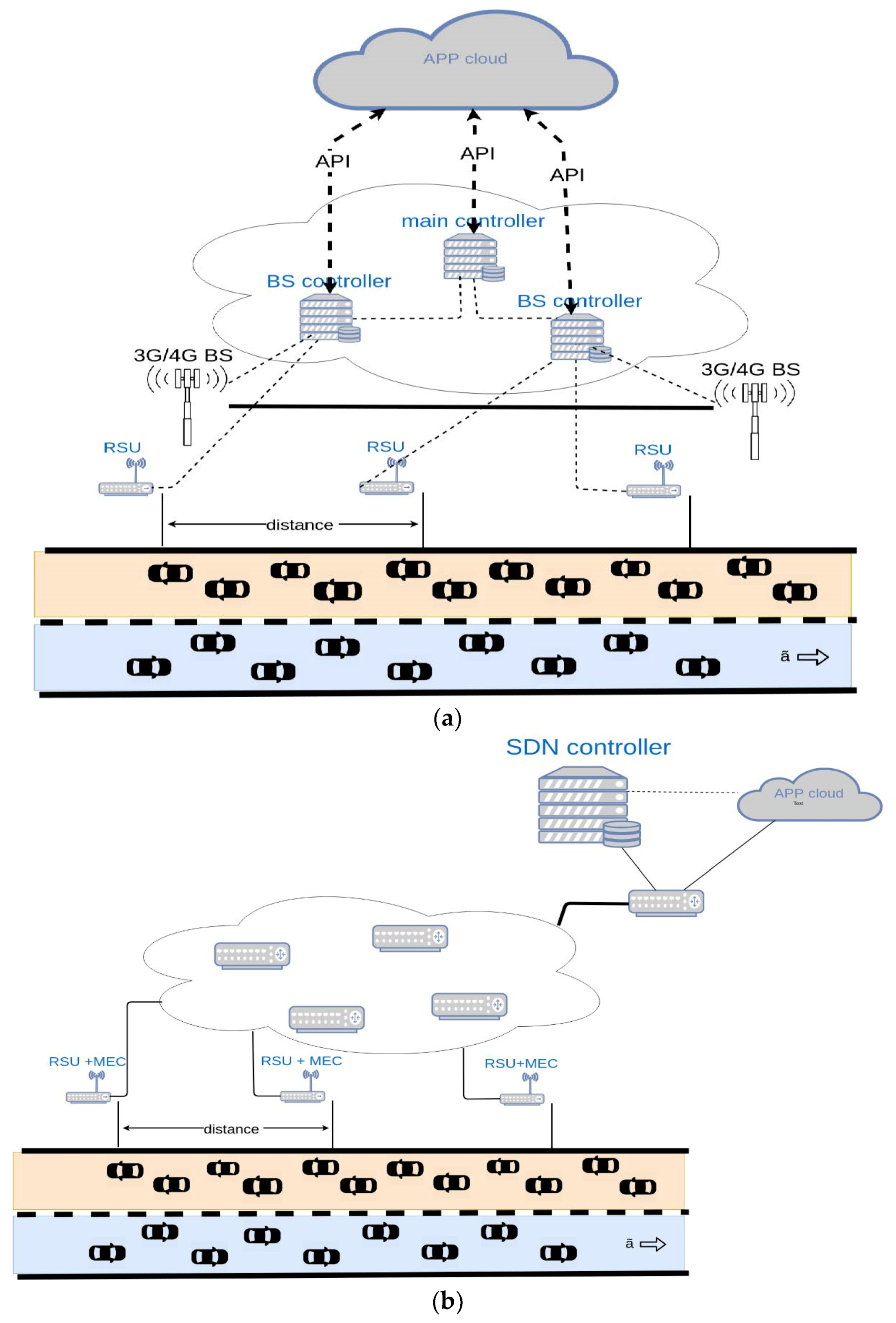
A group of researchers from University of Toulouse reviewed the SDN hybrid architecture for ITS management [29]. The key idea of this architecture is the hybrid control level, which includes the base station controller of the mobile network and a controller of roadside unit (RSU) modules, as well as a central controller to coordinate the actions of different controllers. The central controller creates a global view of the network infrastructure by sending information to the controller of each network with data in the cloud. It sends each controller global rules describing the general behavior of the network, while BS and RSU controllers define specific rules that must be set in each network device. Communication between SDN controllers is performed using a special interface, known as East–West; communication between SDN controllers and the cloud is performed through Application Programming Interfaces (API).
The aim of the experiment was to demonstrate how a global view of the network, combined and enriched with information obtained from the cloud, allows us to more effectively manage network behavior by ultimately providing a service with increased performance. However, this work did not consider the deployment of MEC technology, which represents a main part of our proposed system. This system was mainly dedicated to network management and flexibility at the application layer, while our proposed structure mainly considers traffic management and enhancing routing efficiency by the introduction of MEC servers controlled by an SDN network.
Another research project on this subject comes from the work group from the University of Singapore (School of Electrical and Electronic Engineering Nanyang Technological University, Singapore) [30]. This approach also involved the use of existing mobile network architecture in addition to the implementation of management based on SDN technology. It should be noted that all VANET architecture is divided into segments (Control Regions) which may contain a certain amount of RSUs and which operate a control member (Local Controller); this significantly reduces the delay in the case of transmission of information to the network management unit.
The central network controller is located in its core. The interaction between the central controller and local controllers takes place based on a mobile communication network. The authors called this architecture SDVN—Software-Defined Vehicular Network.
The key parameter chosen in this paper for the simulation and mathematical models was delay. For comparison, three network architectures were selected: A VANET based on the ad hoc on-demand distance vector (AODV) routing protocol, SDVN with a central controller, and SDVN with controllers located within the segments. This work shares the similarity of deploying SDN paradigm with our proposed work. However, we introduce the MEC technology as a main part of our proposed structure, which achieves various benefits in terms of latency and data offloading. Furthermore, this work only presents a structure of the core network with no performance evaluation.
In [31], the authors proposed a context-aware packet-forwarding mechanism for information-centric networking (ICN) based VANETs. The relative geographical position of vehicles, the density and relative distribution of vehicles, and the priority of content were considered during the packet forwarding.
In [32], the authors focused on a vehicle-to-vehicle communication system operating at a road intersection, where the communication links can be either line-of-sight (LOS) or non-line-of-sight (NLOS). The authors presented a semi-empirical analysis of the packet delivery ratio of dedicated short-range communication (DSRC) safety messages for both LOS and NLOS scenarios using a commercial transceiver.
The authors of [33] critically reviewed the existing methods of adaptive traffic signal control in a connected vehicle environment and compared the advantages and disadvantages of those methods.
The proposed architecture provides load balancing between distributed controllers and uses a local view of the network to make better decisions. Both the theoretical model and the simulation results confirmed that the proposed SDVN architecture differs from the existing SDVN with a central controller in terms of latency. The proposed system has the same low latency as the existing VANET.

3. System Structure

In this part the proposed structure for a novel VANET system is introduced. The system comprises two main technologies; SDN technology at the core network and MEC at the RAN. Introducing an SDN paradigm to the VANET became a demand, since it achieves various benefits that include the higher security, latency performance improvement, network congestion reduction and higher routing efficiency. MEC technology provides computing capabilities near to vehicles, which reduces the communication latency and solves the problem of high traffic density. With the introduction of SDN and MEC technologies, traffic from vehicles does not have to pass through the network core; it can be managed and handled at the edge of the access network.
Figure 1a provides the general structure of the VANET system. The system deploys distributed stationary roadside units (RSUs) to assist vehicles. The core network provides an interface to the application server that provides additional services for the vehicles. Vehicles interact with each other, i.e., V2V, and with surroundings, e.g., V2X, over the appropriate reliable radio access interface, e.g., dedicated short range communication (DSRC) and cellular V2X (C-V2X) [34]. DSRC are based on the IEEE 802.11 standard group, which have been modified for vehicular communication. The IEEE 802.11p is the most common radio access technology that has been developed for Mobile ad hoc networks (MANETs), including ad hoc networks for vehicles [35]. The physical layer and the MAC layer of the IEEE 802.11P have been derived from the IEEE 802.11a standard.
The technical requirements of the IEEE 802.11p standard are targeted to speed up to 200 km/h, response time around 100 ms and a communication range of up to 1 km. IEEE 802.11P provides unacceptable performance for ultra-low latency applications, which makes it proper only for safety applications [34,36]. Furthermore, for high density vehicular networks, IEEE 802.11P indicates low performance due to packet collision. This makes the C-V2X more desirable for these applications. To overcome these limitations of the IEEE 802.11.P, and to increase the performance of DSRC compared to that of C-V2X, a new radio access protocol, i.e., IEEE 802.11bd, has been developed. IEEE 802.11bd offers higher modes of operation at a higher throughput.
One of the main design goals of the IEEE 802.11bd was to achieve a throughput at least twice that of IEEE 802.11P at a higher mobility, i.e., the targeted speed of up to 500 km/h. Furthermore, another main advantage of 802.11bd is increasing the communication distance to double of that covered by the IEEE 802.11P. However, IEEE 802.11bd achieves higher benefits and performance compared to the IEEE 802.11P, the main problem associated with the deployment of the 802.11bd is the compatibility with existing systems [36].
The proposed system introduces the multilevel MEC structure and an intelligent core network to the general VANET system structure, as illustrated in Figure 1b. The proposed system comprises three types of communications. The first is the communication between vehicles and referred to as the vehicle-to-vehicle (V2V) communication. The second interaction is the data transferred between vehicles and stationary road infrastructure, i.e., RSU, and is referred as vehicle-to-infrastructure (V2I) communication. The third communication may be hold between vehicles and other surrounding devices, which is referred to as vehicle-to-everything (V2X). These communications are done over appropriate communication interfaces, such as the IEEE 802.11 standard group.
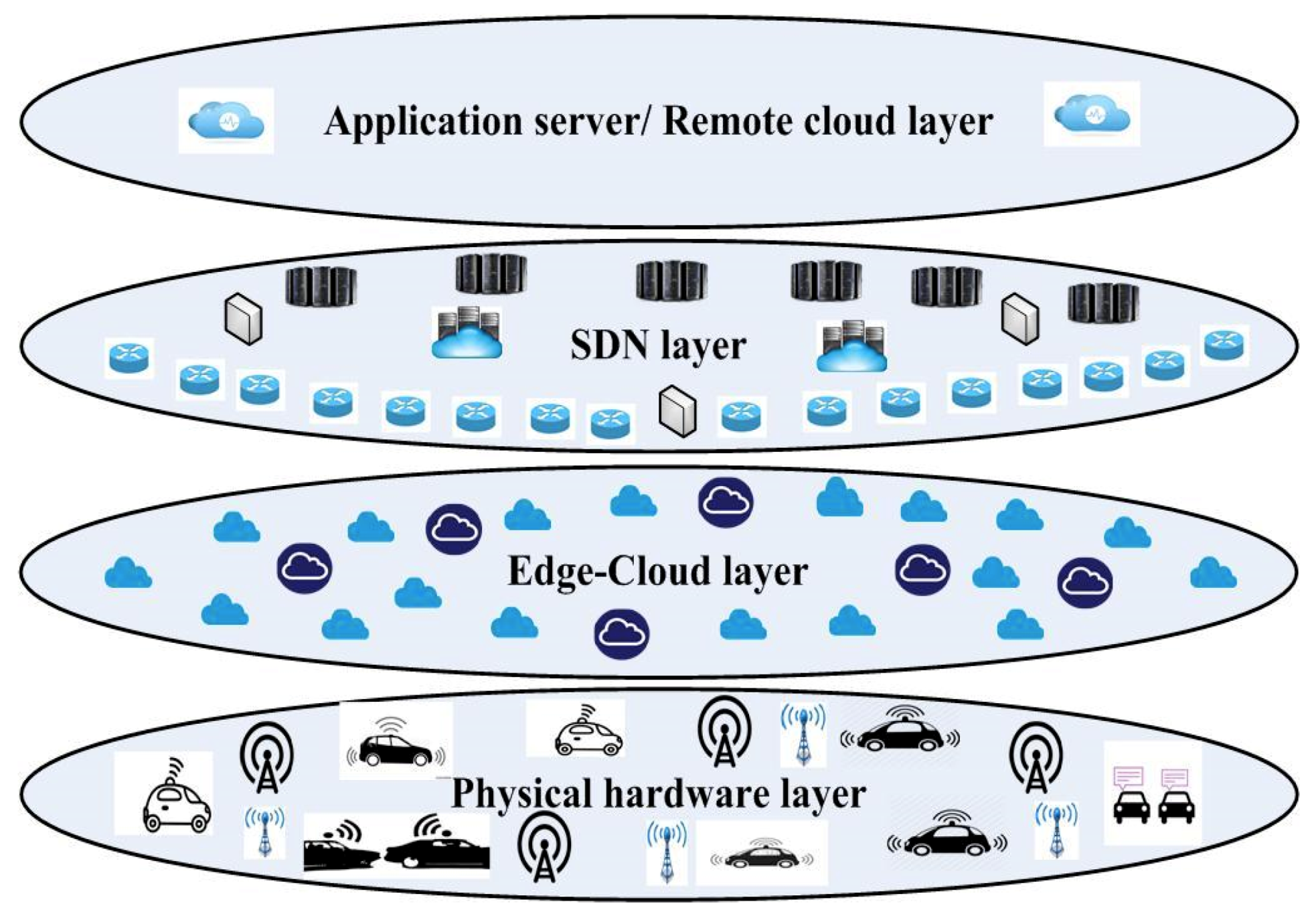
The proposed VANET structure can be viewed as a four layer system, as presented in Figure 2. The first layer represents the physical hardware layer that includes vehicles powered with On-Board Units (OBUs) able to communicate with the distributed RSUs. RSUs are centralized remote management units that are responsible for forwarding and exchanging service control packages. The second layer represents the heterogeneous edge cloud servers deployed at the edge of the RAN. Two main types of MEC servers are considered for the proposed system; micro-cloud edge servers and mini-cloud edge servers. Each RSU is connected to a micro-cloud edge server, as well as the cellular base stations. The micro-cloud edge server is powered with limited computing and energy capabilities. Each group of micro-cloud servers are connected with a mini-cloud edge server, with higher computing and energy resources.
The third layer represents the SDN network deployed at the core network. This layer contains two main sub-layers; data plane sub-layer and control plane layer. The data plane layer contains distributed OpenFlow switches that support the appropriate version of the OpenFlow protocol. The control plane contains distributed SDN controllers that control and manage the whole network. The SDN network is managed via application programming interfaces (APIs). The core network provides an interface to the higher layer that represents the application server.
The proposed system provides two main network interfaces at the first layer. The first interface is the car-car and the second is the car-infrastructure network. This can be done over the appropriate IEEE 802.11 communication interface, as previously introduced. The distributed edge servers in the second layers are connected over a high speed fiber wireless (FiWi) network [37].
Where, each RSU station is connected to a MEC server to provide the computing capabilities at the edge of the access network. This in turn, offloads the data and reduces the traffic passed to the core network, which reduces network congestion and packet loss.
4. Latency-Aware Offloading Algorithm for Multilevel MEC VANET System

In this part, we develop an offloading algorithm for the proposed VANET system. The algorithm manages and controls the offloading of computation tasks from vehicles to the distributed edge servers, in a way that achieves higher latency efficiency. The algorithm is based on the general offloading algorithm developed in [38], for multilevel MEC based systems.
The proposed offloading algorithm increases the interactivity of vehicles with the surrounding devices, i.e., V2X. This provides a novel scheme for innovation of service provision in vehicular systems. The proposed algorithm assumes that each OBU is empowered with a decision engine that decides the offloading process and thus, implements the proposed algorithm.
The proposed offloading algorithm considers the quality of service (QoS) latency for each computing task [39]. The task should be handled within the QoS latency, either execute the task locally on the vehicle or offload it to the nearby edge server connected to RSU or the cellular base station.

4.1. Annotation

The abbreviations used for developing the offloading algorithm are introduced in Table 1. Algorithm 1 introduces the considered steps of the offloading algorithm for MEC based VANET. This algorithm is implemented in the decision engine of the OBU. This algorithm comprises the second algorithm (Algorithm 2) that introduces the required steps for accepting or rejecting offloading requests at the heterogeneous edge cloud servers.
Algorithm 1. Latency-aware offloading algorithm for multilevel based VANET system.
Input: Q, NCYC, and K
Output: Doff-OBU
1:Initialize Q
2:Calculate K, S
3:Calculate Tex-OBU
4:If (Tex-OBU ≤ Q)
5:  Doff-OBU = 0
6:  Handle task locally
7: else
8:  Doff-OBU = 1
9:  Check first and second levels of offloading [Call Algorithm 2]
10:end if
Algorithm 2. Processing offloading requests at the heterogeneous edge cloud servers.
Input: Q, NCYC, and K
Output: DT-Micro-cloud-acc-off and DT-Mini-cloud-acc-off
01:Micro-cloud edge server receives the offloading request
02:Micro-cloud edge server process the request:
03:Calculate Tex-Micro-cloud, TT-Micro-cloud
04:If (TT-Micro-cloud ≤ Q)
05: DT-Micro-cloud-acc-off = 1
06: Transmit the appropriate response
07: Micro-cloud edge server handle the task
08:else
09: DT-Micro-cloud-acc-off = 0
10: Forward the offloading request to mini-cloud edge server
11: Mini-cloud edge server process the request:
12: Calculate Tex-Mini-cloud, TT-Mini-cloud
13:  If (TT-Mini-cloud ≤ Q)
14:   DT-Mini-cloud-acc-off = 1
15:   Transmit the appropriate response
16:   Mini-cloud edge server handle the task
17: else
18:   DT-Mini-cloud-acc-off = 1
19:   Block the task
20:  End if
21:end if

4.2. Offloading Model

For all input tasks, the OBU checks the availability of local execution at first. If it fails to execute within the QoS latency, Q, then it checks the possibility of offloading. At first, the decision engine of OBU calculates the total time required to execute the task locally, Tex-OBU. This time is calculated based on the available processing resources of the OBU as illustrated in Equation (1).
T e x - O B U = N C Y C R O B U ,    R O B U f O B U
N C Y C = K . S
Then, the OBU decides the local execution or the offloading by calculating the decision variable of offloading, Doff-OBU. This can be calculated as following:
D o f f - O B U = I ( T e x - O B U , τ ) = { 0 ?        I F    ( T O B U     τ ) 1 ?        I F    ( T O B U   >   τ )
For negative decision, the task is processed locally. Otherwise, the task is offloaded to the nearby micro-cloud edge server that decides whether to accept the offloading request or forward the request to the corresponding mini-cloud edge server. Once a micro-cloud edge server receives an offloading request from an OBU, it extracts the task information and starts to process the request. The decision engine of the micro-cloud edge server calculates the total time required to execute the task at the micro-cloud server, Tex-Micro-cloud, based on the current available resources.
T e x - M i c r o - c l o u d = N C Y C R M i c r o - c l o u d ,    R M i c r o - c l o u d f M i c r o - c l o u d
Then, the total time required to handle the task at the micro-cloud edge server, TT-Micro-cloud, is calculated as following:
T T - M i c r o - c l o u d = T e x - M i c r o - c l o u d +   T T x + T R x
T T x = t t r a n s + T p r o
Finally, the decision engine decides whether to accept the offloading request or reject it, by calculating the decision variable of accepting offloading, as following:
D T - M i c r o - c l o u d - a c c - o f f = I ( T T - M i c r o - c l o u d , τ ) = { 1 ?        I F    ( T T - M i c r o - c l o u d     τ ) 0 ?        I F    ( T T - M i c r o - c l o u d   >   τ )
For a positive decision, the micro-cloud edge sever sends a corresponding message to the OBU to set for the offloading process. If the micro-cloud edge server cannot handle the offloading request, it forwards the request message to the corresponding mini-cloud edge server. The decision engine of the mini-cloud edge server receives the request message and extracts the task information to process the request. Based on the current available resources of mini-cloud edge server, the decision engine calculates the total time required to handle the task, as following:
T e x - M i n i - c l o u d = N C Y C R M i n i - c l o u d ,    R M i n i - c l o u d f M i n i - c l o u d
T T - M i n i - c l o u d = T e x - M i n i - c l o u d + T T x + T R x
Then, the decision of accepting or rejecting offloading request is calculated as following:
D T - M i n i - c l o u d - a c c - o f f = I ( T T - M i n i - c l o u d , τ ) = { 1 ?        I F    ( T T - M i n i - c l o u d     τ ) 0 ?        I F    ( T T - M i n i - c l o u d   >   τ )
For a positive decision, the mini-cloud edge server accepts the offloading request and the offloading process starts. For the negative decision of offloading, the task is blocked.

5. Experimental Results and Performance Evaluation

In this part, the performance of the proposed VANET system and the introduced latency-aware offloading algorithm is evaluated. The proposed system was experimentally tested over a real hardware to validate the system. Furthermore, the system was simulated for high density VANET network to evaluate the performance of the offloading scheme.

5.1. Evaluation of the Proposed System Structure

The analysis of the results from the full-scale experiment to identify key indicators for the VANET was based on a traffic dump recorded on the radio interface of one of the devices. The traffic was recorded using the utility built into the device. The experiment was performed in an open space, and the maximum removal of network elements from each other was 300 m. Based on the tests performed, the set of considered Wave Short Message Protocol (WSMP) package parameters, which were sufficient for statistical analysis, are indicated in Table 2.
The total packet size was 255 bytes. The data presented above were obtained from the test results of a segment of the transport self-organizing network and will be used in the future for modeling and calculating the RSU load. The key parameters of the functioning segment of the VANET model are presented in Table 3.
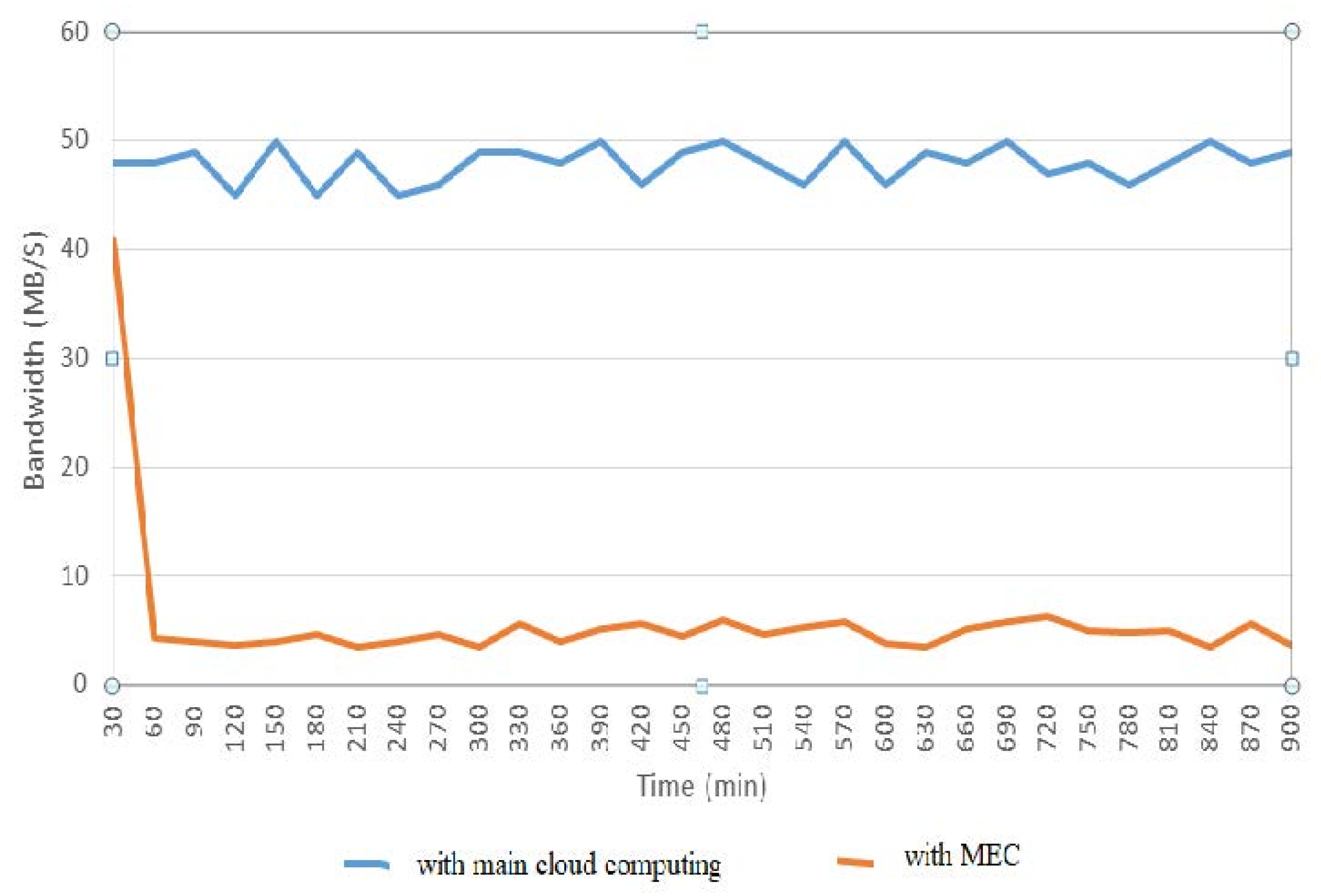
To determine the effectiveness of the VANET with control based on software-defined networking, a series of five experiments were conducted for the architecture shown on Figure 1b. The duration of each experiment was 15 h. During the experiment, 30 Raspberry pi devices were used to imitated vehicle OBUs, and the number of RSUs was 10 devices. The study scenario involved a serial connection of the OBU to the RSU at specified intervals, which was used to simulate the movement of vehicles. In situations where more than three OBUs were connected to one RSU, an additional delay of 5 ms was introduced. For performance evaluation of the proposed structure, the bandwidth and the packet loss are considered to be the performance metrics. During experimental evaluation, we considered measuring average bandwidth for two main cases; the system was deployed with the main cloud only and the system was deployed with the MEC. The results of the experiments are shown in Figure 3.
According to the experimental results, the average packet loss amounted to 0.082%; it is possible to conclude that the controller coped with the requirement of reducing network load, thus confirming the efficacy of the test approach. This can be interpreted by the introduction of MEC servers with the distributed SDN paradigm controlling and managing the traffic. This reduces the traffic congestion and the packet loss. Thus, the overall network load is reduced and the network efficiency in terms of latency and reliability is increased.
The effect of distances between RSU stations on the packet delivery time and amount of data offloaded to the core network was checked for the proposed system. Three scenarios were considered for such evaluation; in each scenario three cases were considered. In each scenario, certain value of flow rate of cars was considered. However, the three considered cases, in each scenario, indicate different values of the cars’ mobility. The considered value of flow rate for each scenario is indicated in Table 4. Table 5 indicates the value of cars’ mobility considered in each case for the three considered scenarios.
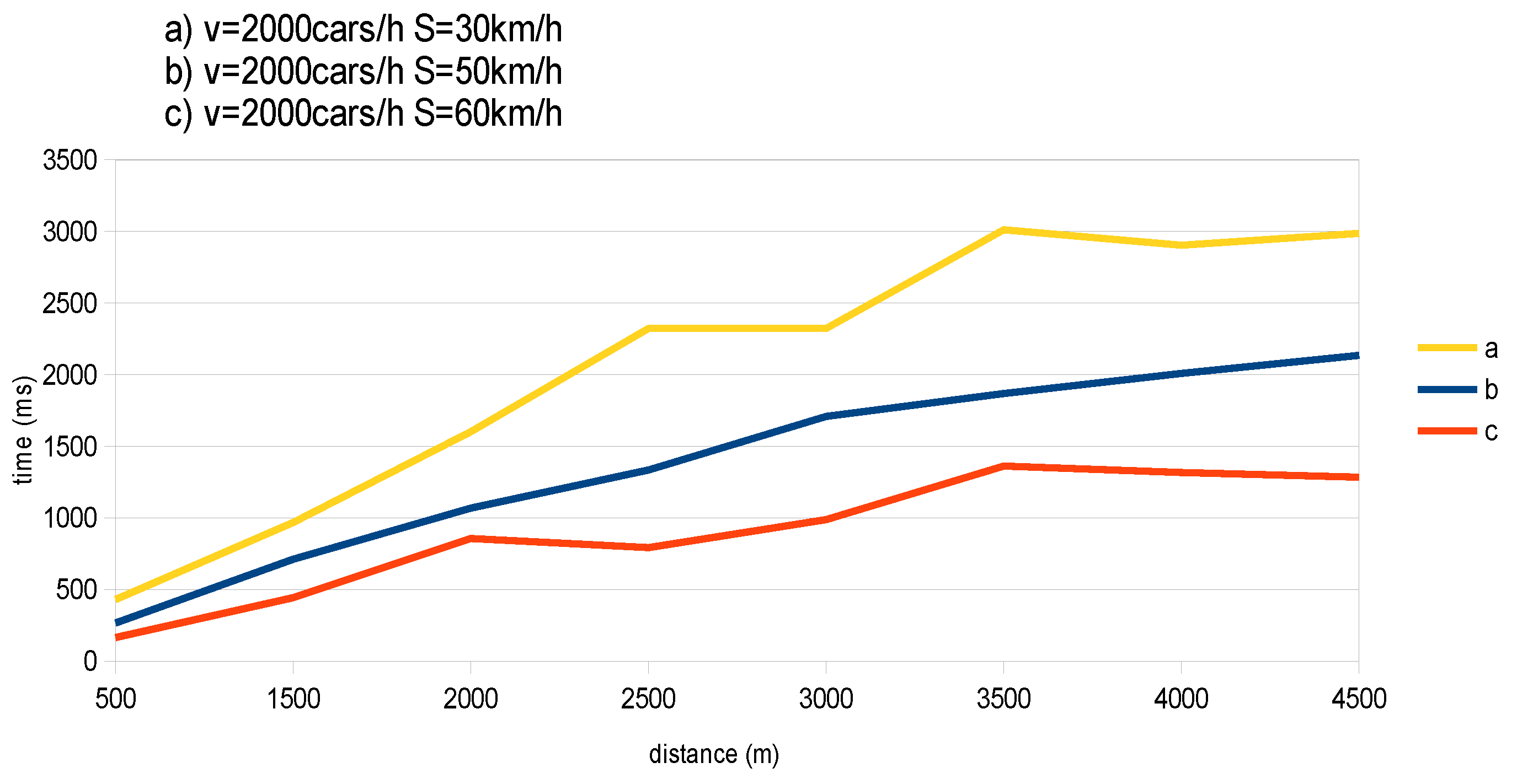
Scenario (A): In this scenario, three cases were considered with a flow rate of 2000 cars per hour and respective speeds of 30 km/h, 50 km/h, and 60 km/h; the size of packets was 30 bytes. Figure 4 illustrates the different values of packet delivery time with the different distances between RSU stations. Results indicated that, with the increase of distance between RSU stations the value of the packet delivery time is increased; for all considered cases (i.e., various considered speeds). Moreover, with the increase of car mobility, the average value of packet delivery time was reduced. Based on the data obtained, the best packet delivery time was observed at a speed of 60 km/h.
Figure 5 illustrates the amount of offloaded data to the backhaul network with the distances between RSU stations. As the distance between adjacent RSU stations increased, the amount of data offloaded to the backhaul was increased, which degrades system performance. Moreover, with the increase of cars’ mobility, the amount of data passed to the core network was reduced.
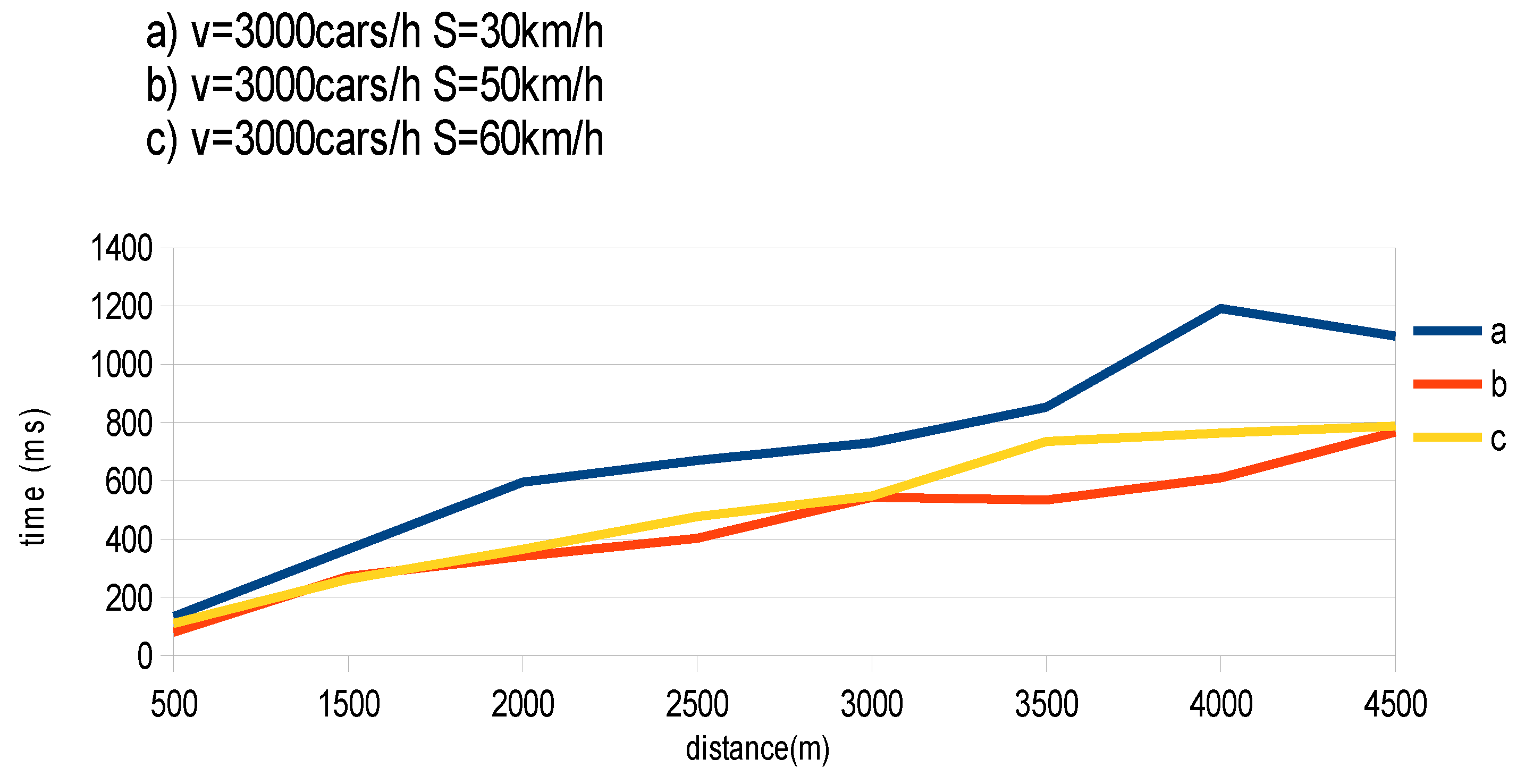
Scenario (B): In this scenario, the considered flow rate is 3000 cars per hour. Figure 6 illustrates the obtained values of the packet delivery time for different values of distance between RSU stations, for the considered value of flow rate. With the increase of flow rate of cars the average value of the packet delivery time was reduced. This can be clearly seen, by comparing Figure 4 and Figure 6.
The packet delivery time results for cars with speeds of 50 km/h and 60 km/h were almost the same; the longest package delivery time will be for cars moving at a speed of 30 km/h. This can be interpreted as that of scenario A.
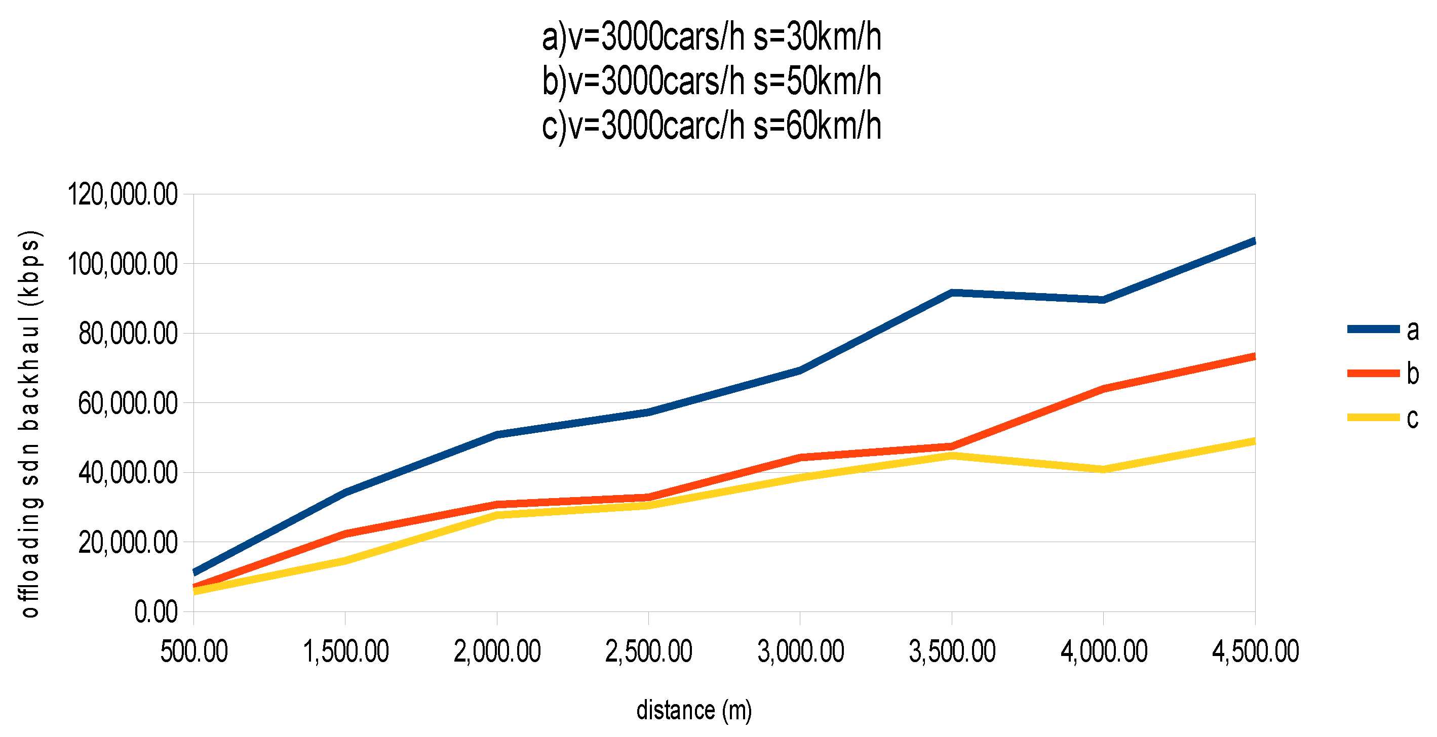
Figure 7 illustrates the mound of offloaded data to the backhaul network for the second scenario. Results indicate that the amount of data offloaded to the backhaul increases with the increase of distance between adjacent RSU stations. Moreover, with the increase of car mobility, the amount of data passed to the core network was reduced. Comparing results for scenario A and B, we can conclude that the amount of data offloaded to the backhaul increases with the increase of low rate of cars. This is because of the increase of number of cars produces much data that cannot be handled by the MEC servers due to the limited computing capabilities, which in turn, is moved to the core network.
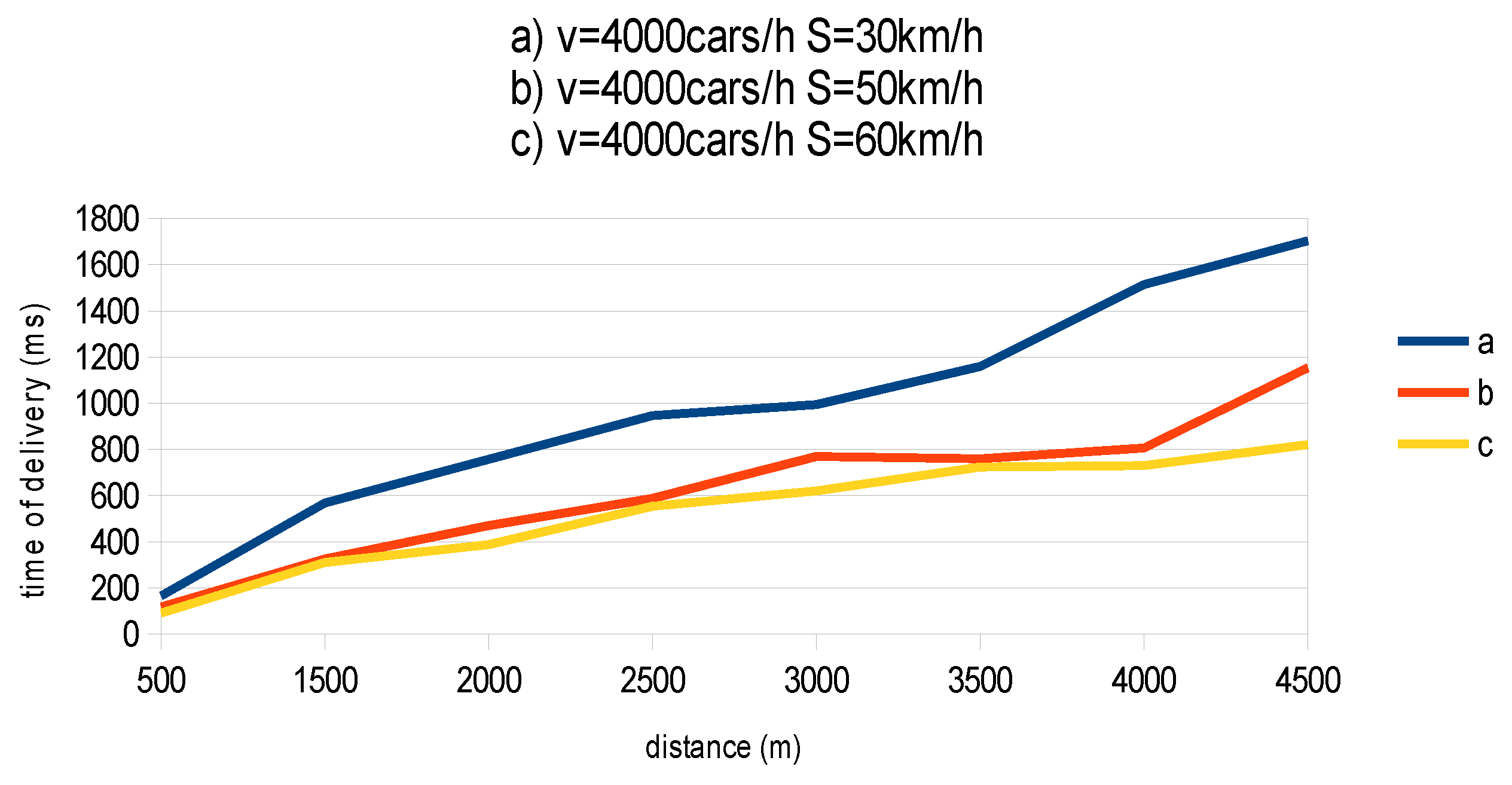
Scenario (C): In this scenario, the considered traffic intensity was 4000 cars per hour. The measured values of packet delivery time for different values of distance between RSU stations, for this scenario, are indicated in Figure 8. The average value of packet delivery time for this scenario was approximately the same as of scenario (B). It was also clear that with the increase of distance between RSU stations, the value of packet delivery time is increased. However, it was decreased with the increase of car mobility. The shortest packet delivery time was for cars moving at 60 km/h, and it was twice the delivery time attained for packets for cars moving at 30 km/h.
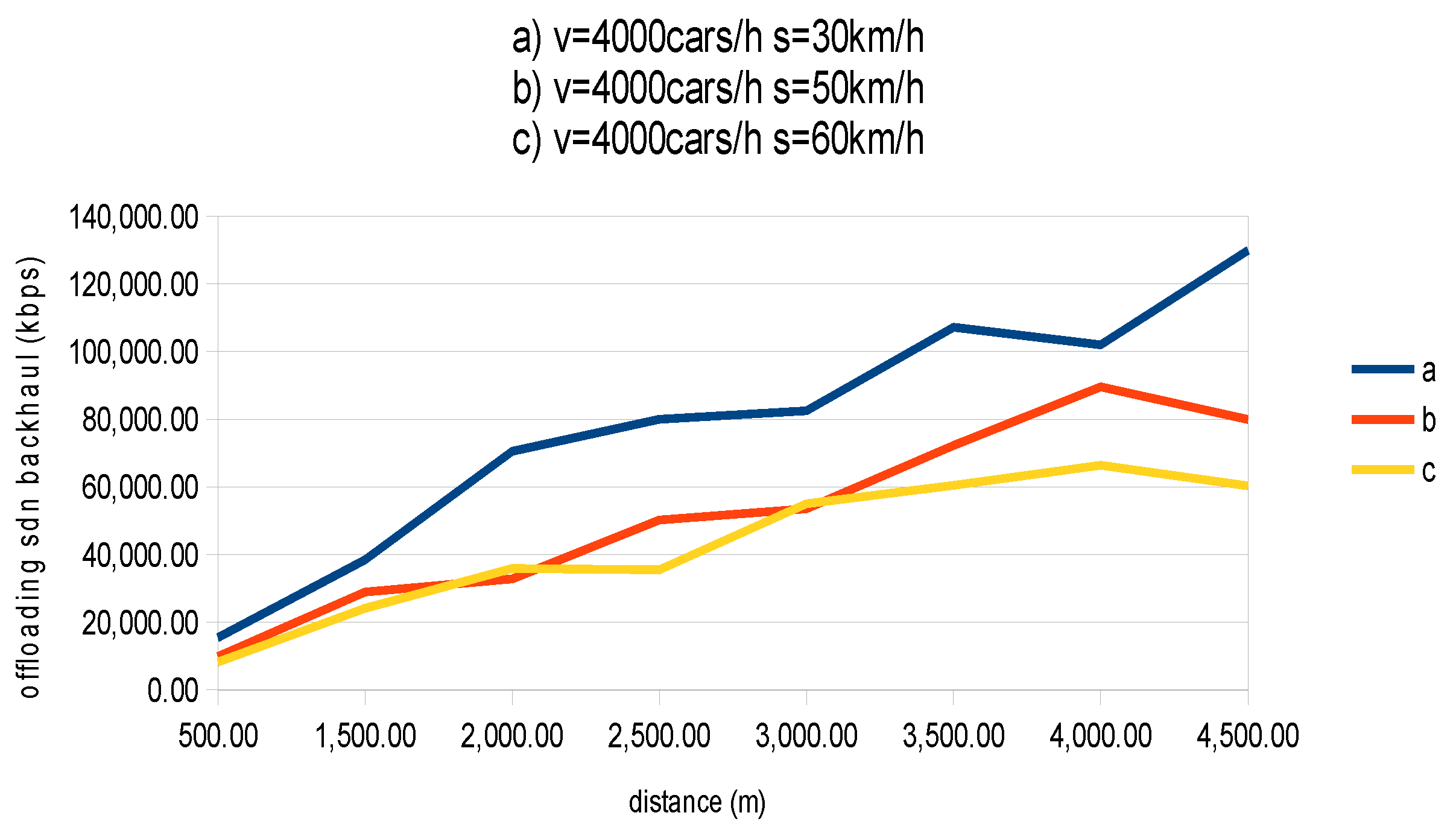
Figure 9 introduces the results for scenario C in terms of data offloaded to the backhaul network. Results indicate the same attribute as in the previous two scenarios. Also, the data offloaded to the backhaul network in this case was higher than that of the previous two scenarios; this is because of the higher flow rate considered in this scenario.

5.2. Performance Evaluation of the Proposed Offloading Algorithm

The proposed offloading algorithm is implemented for the proposed system and simulated over a reliable simulation environment for different simulation cases. The system is simulated over the Matlab environment, with the simulation parameters introduced in Table 6.
The considered tasks were heterogeneous in terms of size, and equivalent to the workload of real images, web pages and text messages. Two simulation scenarios are considered. The first scenario, scenario (I), was introduced to check the effect of the QoS latency on the proposed offloading model. In this scenario, three cases were considered; in each case a certain value for the QoS latency was assumed. The second scenario is scenario (II), which was introduced to compare the proposed offloading algorithm with the local execution and traditional offloading systems.
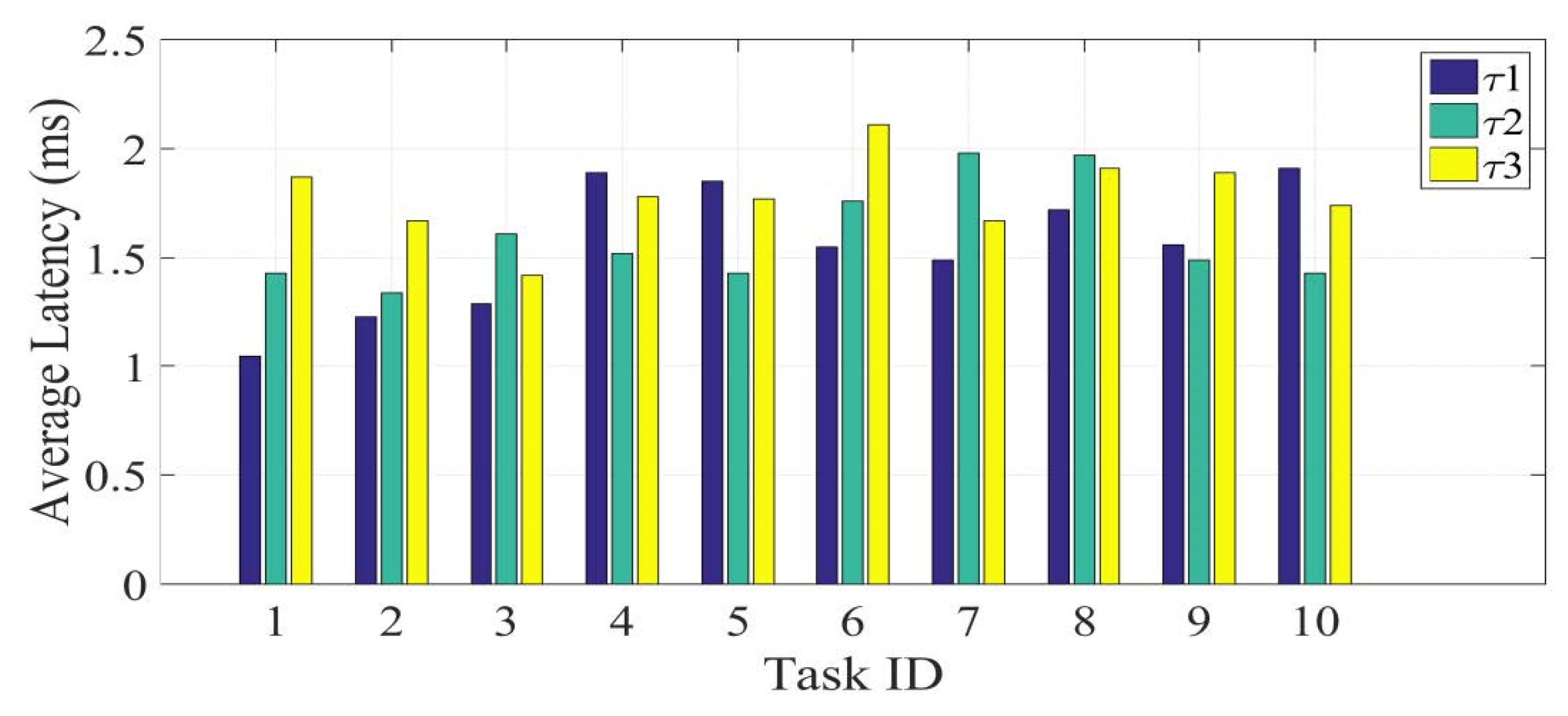
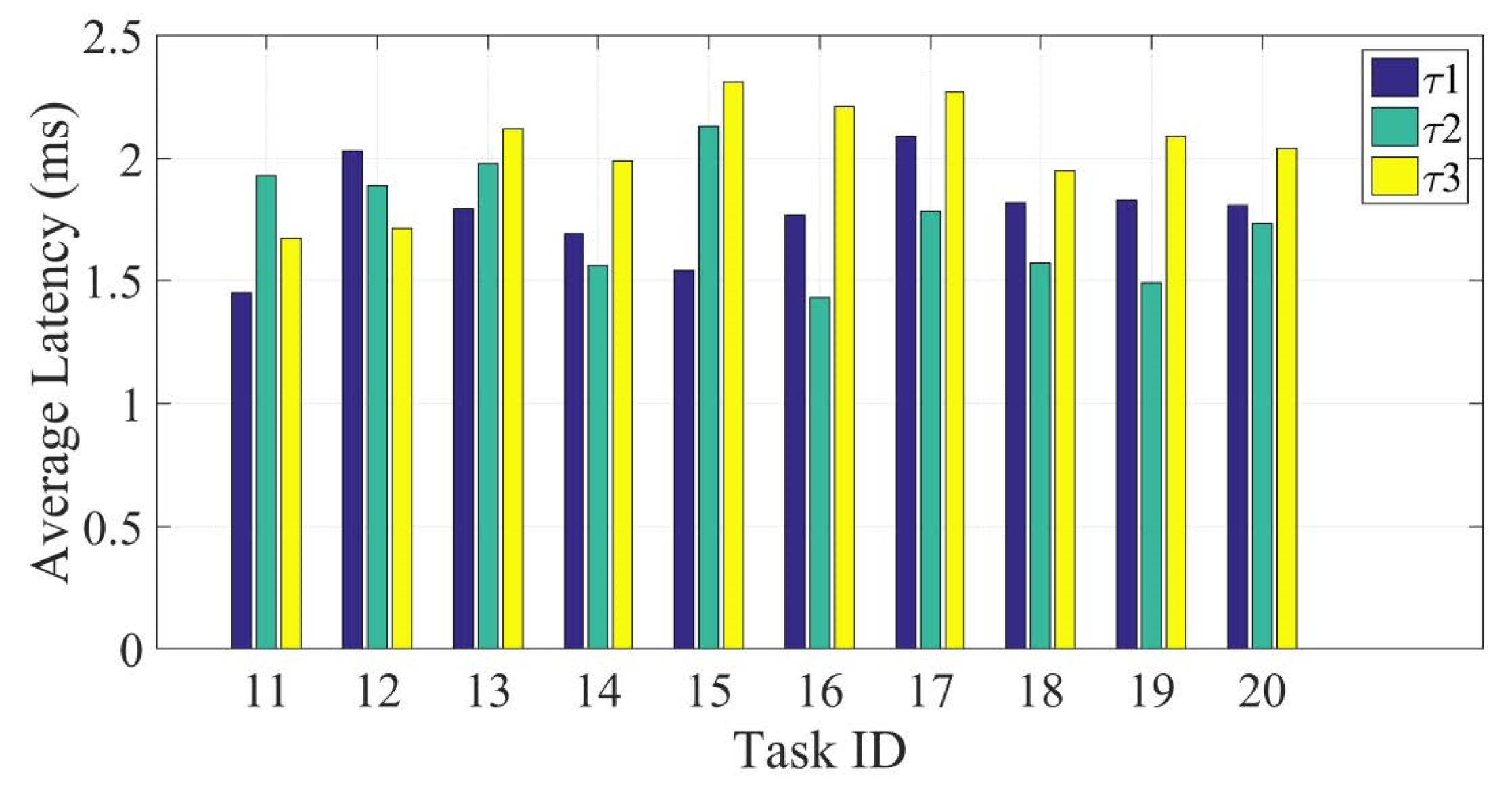
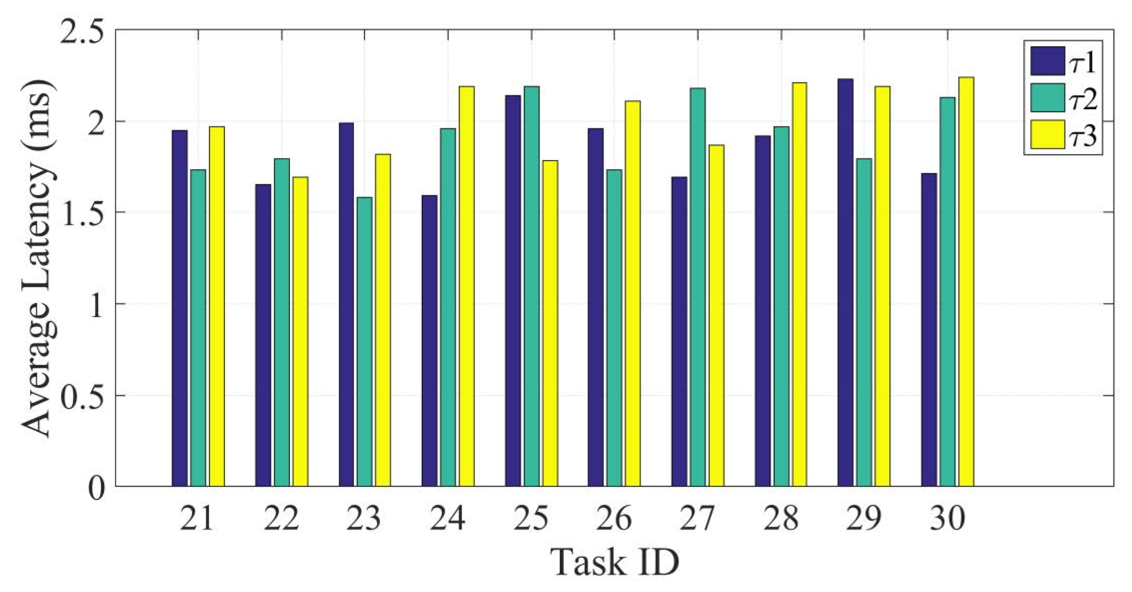
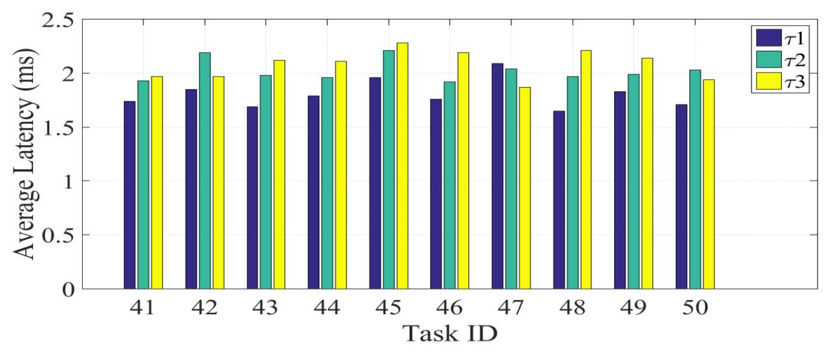
Scenario (I): Table 7 indicates values for QoS latency, Q, for the considered fifty tasks, arranged as a five group of tasks. Figure 10, Figure 11, Figure 12, Figure 13 and Figure 14 provide the average latency for handling the considered tasks, for the three considered values of QoS latency. As the QoS latency, Q, increases, the opportunity for offloading and unloading OBU resources increases.
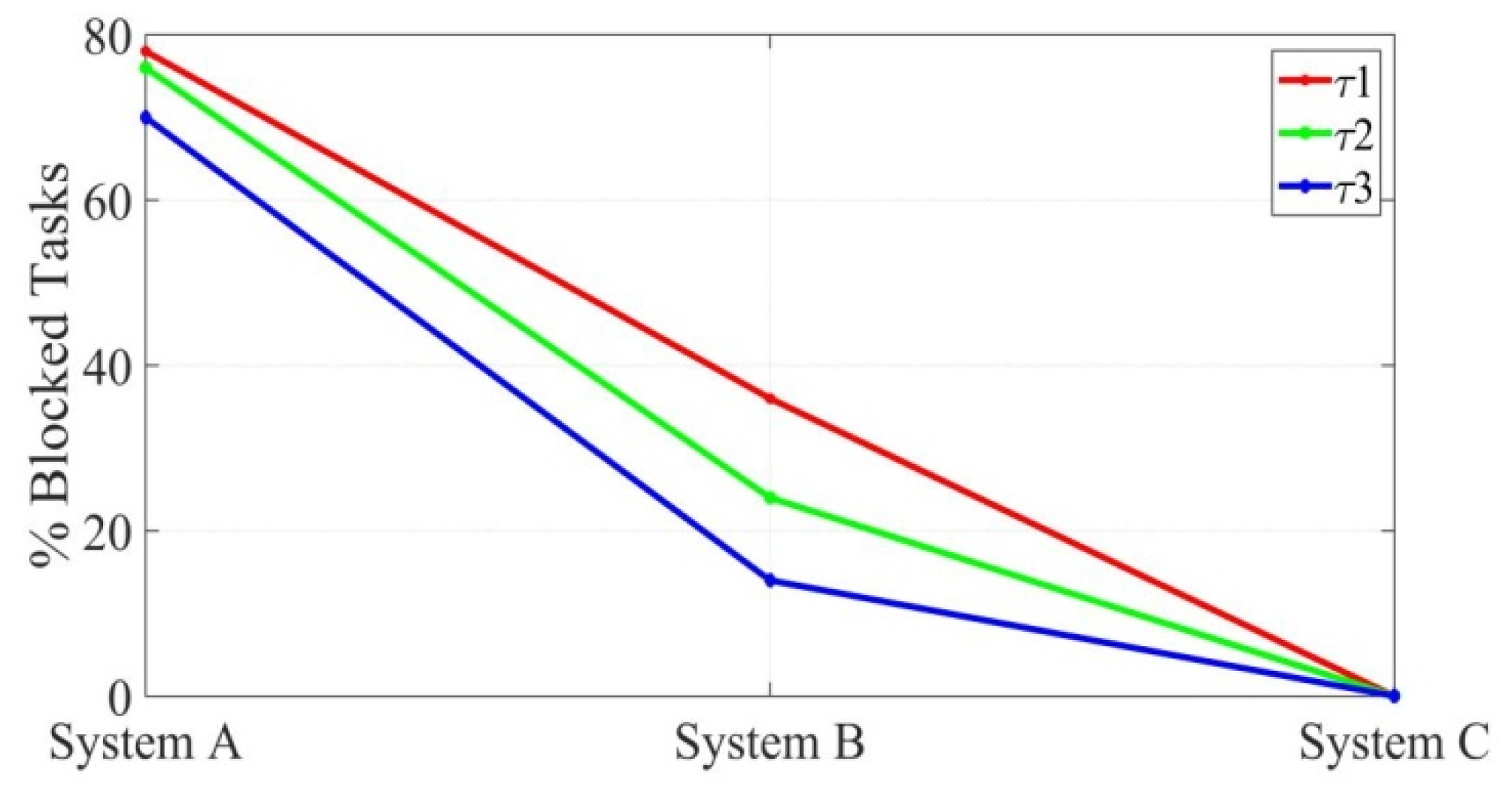
Scenario (II): In this scenario, we considered three main systems for evaluation our proposed system. The first system, system A, represents the local execution, where no edge servers are deployed and no offloading processes are considered. The second system, system B, represents the VANET system with one level of offloading. This system deploys only one type of edge servers connected to RSUs and cellular base stations. The third system, system C, represents the proposed system. Figure 15 indicates the percentage of blocked tasks of each system, for the three values of the QoS latency, Q. The proposed system achieved higher efficiency in terms of blocking tasks, since it provides resources near to users without loading OBUs.

6. System Realization

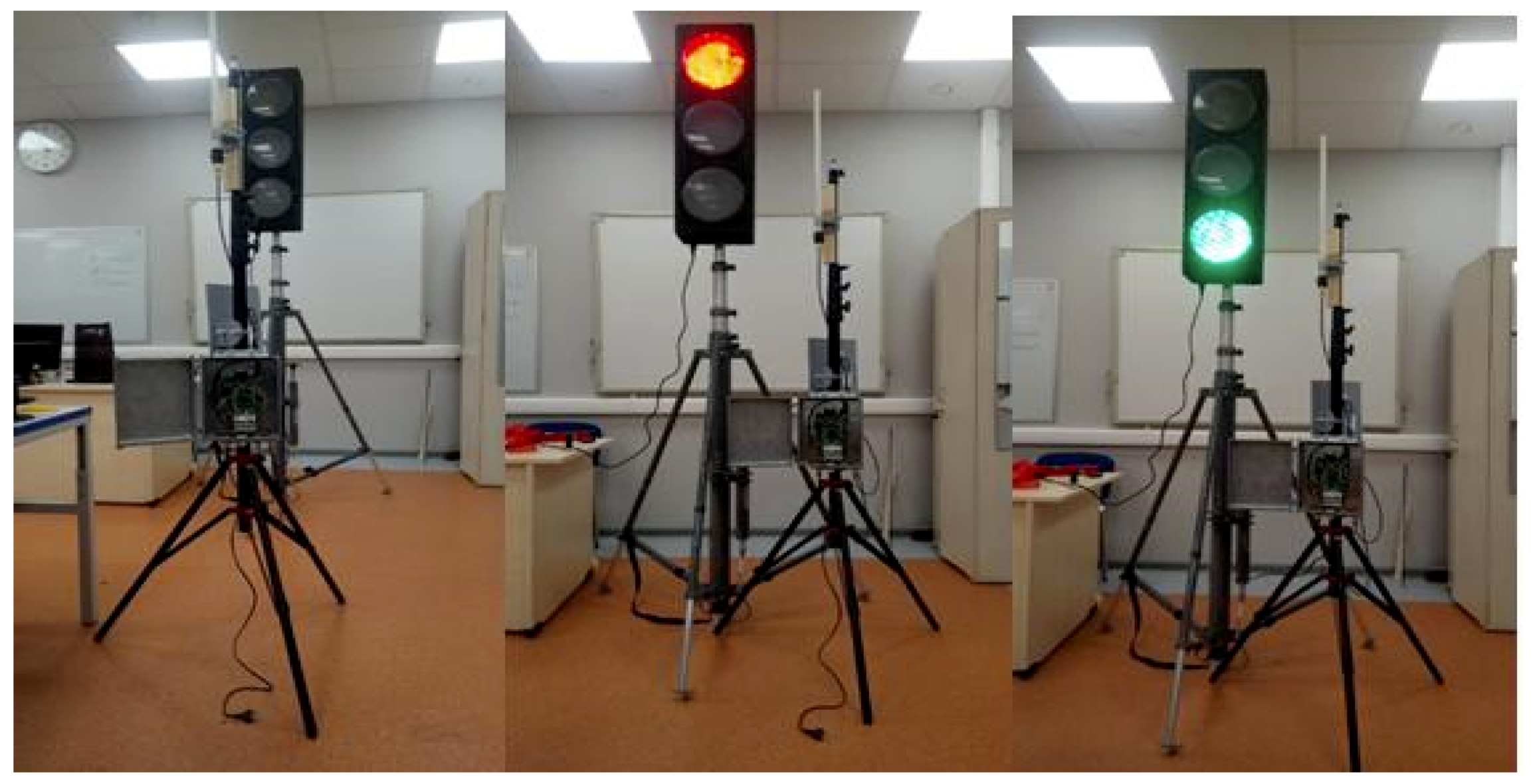
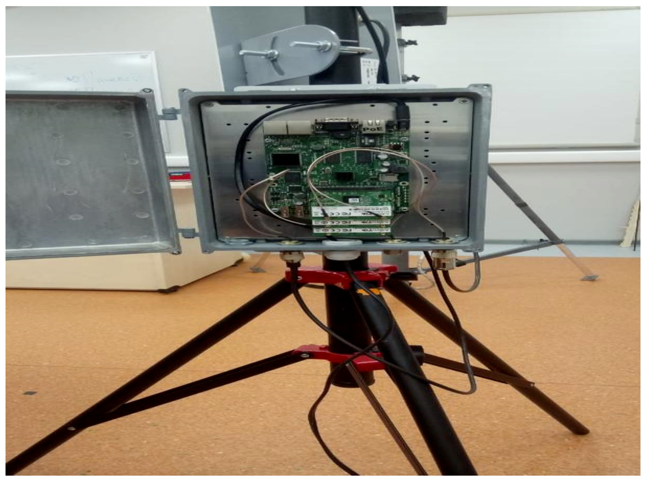
In this part, the proposed system with the comprised algorithms is realized. The system was constructed with RSUs impeded to traffic lights on the roads. The use of these devices in the aggregate will give the possibility of unloading road traffic and allow emergency services to travel without traffic jams. Screens of the conducted real system and involved hardware are presented in Figure 16 and Figure 17.
The RSU, in turn, was implemented on the basis of a MikroTik RouterBOARD 435G motherboard and a MikroTik RouterBOARD R52n-M miniPCI network card. Table 8 shows the characteristics of the RouterBOARD 435G, while Table 9 shows the characteristics of the Router BOARD R52n-M.

7. Conclusions

Currently, the situation of roads becomes increasingly tense due to the increase in the number of cars, the scaling of the road transport network, population growth, and many other factors. In this work, we have developed an intelligent transport system based on MEC and SDN technologies to automate traffic, increase driver and pedestrian safety, and monitor traffic violations. The system deploys the distributed SDN scheme to manage and control MEC servers connected to RSU stations. The system addresses the problems of inefficient data routing and latency, associated with ITS. The introduction of MEC and SDN with the developed offloading algorithm achieved better efficiency in terms of packet delivery time and packet loss. Furthermore, the traffic offloaded to the core network is reduced and thus, reduces network congestion. During the work on this subject, we considered the most promising approaches to the management of ITS, identified key indicators of the functioning of VANET segments, and experimentally proved the advantages of software-defined network management for ITS. A series of experiments were conducted with different densities and different speeds of traffic at different locations relative to RSUs. The experimental results validate the proposed structure and the comprised algorithms.

Author Contributions

Conceptualization, A.V. and A.K. (Andrey Koucheryavy); funding acquisition, A.V.; investigation, A.K. (Abdukodir Khakimov), A.M. and A.A.A.; methodology, A.M. and A.K. (Andrey Koucheryavy); project administration, A.V.; software, A.K. (Abdukodir Khakimov), A.M. and A.A.A.; validation, A.K. (Andrey Koucheryavy); visualization, A.K. (Abdukodir Khakimov); writing—original draft, A.M. and A.A.A.; writing—review & editing, A.V. and A.K. (Andrey Koucheryavy)

Funding

This research was funded by the Ministry of Education and Science of the Russian Federation, in the framework of the Federal Target Program “Research and development on priority directions of scientific technological complex of Russia for 2014–2020” (agreement number 14.604.21.0165, unique identifier project RFMEFI60417X0165).

Conflicts of Interest

The authors declare no conflict of interest.

References

  1. Osseiran, A.; Boccardi, F.; Braun, V.; Kusume, K.; Marsch, P.; Maternia, M.; Queseth, O.; Schellmann, M.; Schotten, H.; Taoka, H.; et al. Scenarios for 5G Mobile and Wireless Communications: The Vision of the METIS Project. IEEE Commun. Mag. 2014, 52, 26–35. [Google Scholar] [CrossRef]
  2. Akyildiz, I.F.; Nie, S.; Lin, S.C.; Chandrasekaran, M. 5G Roadmap: 10 Key Enabling Technologies. Comput. Netw. 2016, 106, 17–48. [Google Scholar] [CrossRef]
  3. The Tactile Internet. ITU-T Technology Watch Report. ITU, 2014. Available online: https://www.itu.int/dms_pub/itu-t/opb/gen/T-GEN-TWATCH-2014-1-PDF-E.pdf (accessed on 31 March 2019).
  4. Feasibility Study on New Services and Markets Technology Enablers for Critical Communications; 3GPP TR 22.862; 3GPP: Valbonne, France, 2016.
  5. IMT Vision—Framework and Overall Objectives of the Future Development of IMT for 2020 and Beyond. Recommendation ITU-R M.2083-0. ITU. 2015. Available online: https://www.itu.int/dms_pubrec/itu-r/rec/m/R-REC-M.2083-0-201509-I!!PDF-E.pdf (accessed on 31 March 2019).
  6. Study on Scenarios and Requirements for Next Generation Access Technologies; 3GPP TR 38.913; 3GPP: Valbonne, France, 2017.
  7. Ateya, A.; Muthanna, A.; Makolkina, M.; Koucheryavy, A. Study of 5G Services Standardization: Specifications and Requirements. In Proceedings of the 2018 10th International Congress on Ultra Modern Telecommunications and Control Systems and Workshops (ICUMT), Moscow, Russia, 5–9 November 2018; pp. 1–6. [Google Scholar] [CrossRef]
  8. Chen, S.; Hu, J.; Shi, Y.; Peng, Y.; Fang, J.; Zhao, R.; Zhao, L. Vehicle-to-Everything (V2X) Services Supported by LTE-based Systems and 5G. IEEE Commun. Stand. Mag. 2017, 1, 70–76. [Google Scholar] [CrossRef]
  9. Zhu, L.; Yu, F.R.; Wang, Y.; Ning, B.; Tang, T. Big Data Analytics in Intelligent Transportation Systems: A Survey. IEEE Trans. Intell. Transp. Syst. 2019, 20, 383–398. [Google Scholar] [CrossRef]
  10. Cheng, X.; Zhang, R.; Chen, S.; Li, J.; Yang, L.; Zhang, H. 5G Enabled Vehicular Communications and Networking. China Commun. 2018, 15, iii–vi. [Google Scholar] [CrossRef]
  11. Elshenawy, M.; Abdulhai, B.; El-Darieby, M. Towards a Service-oriented Cyber–physical Systems of Systems for Smart City Mobility Applications. Future Gener. Comput. Syst. 2018, 79, 575–587. [Google Scholar] [CrossRef]
  12. Sharma, S.; Kaul, A. A Survey on Intrusion Detection Systems and Honeypot based Proactive Security Mechanisms in VANETs and VANET Cloud. Veh. Commun. 2018, 12, 138–164. [Google Scholar] [CrossRef]
  13. Woo, H.; Lee, M. A Hierarchical Location Service Architecture for VANET with Aggregated Location Update. Comput. Commun. 2018, 125, 38–55. [Google Scholar] [CrossRef]
  14. Modesto, F.M.; Boukerche, A. SEVeN: A Novel Service-based Architecture for Information-centric Vehicular Network. Comput. Commun. 2018, 117, 133–146. [Google Scholar] [CrossRef]
  15. Yaqoob, I.; Ahmad, I.; Ahmed, E.; Gani, A.; Imran, M.; Guizani, N. Overcoming the Key Challenges to Establishing Vehicular Communication: Is SDN the Answer? IEEE Commun. Mag. 2017, 55, 128–134. [Google Scholar] [CrossRef]
  16. Agarwal, P. Technical Review on Different Applications, Challenges and Security in VANET. J. Multimed. Technol. Recent Adv. 2017, 4, 21–30. [Google Scholar]
  17. Jameel, F.; Hamid, Z.; Jabeen, F.; Javed, M.A. Impact of Co-channel Interference on the Performance of VANETs under α-μ Fading. AEU-Int. J. Electron. Commun. 2018, 83, 263–269. [Google Scholar] [CrossRef]
  18. Aliyu, A.; Abdullah, A.H.; Kaiwartya, O.; Cao, Y.; Usman, M.J.; Kumar, S.; Lobiyal, D.K.; Raw, R.S. Cloud Computing in VANETs: Architecture, Taxonomy, and Challenges. IETE Tech. Rev. 2018, 35, 523–547. [Google Scholar] [CrossRef]
  19. Feng, B.; Kong, X.; Yao, H.; Li, J.; Peng, J. Study on Routing Protocol Based on Traffic Density in VANET. Int. J. High Perform. Comput. Netw. 2017, 10, 481–487. [Google Scholar] [CrossRef]
  20. Cooper, C.; Franklin, D.; Ros, M.; Safaei, F.; Abolhasan, M. A Comparative Survey of VANET Clustering Techniques. IEEE Commun. Surv. Tutor. 2017, 19, 657–681. [Google Scholar] [CrossRef]
  21. Hussain, R.; Bouk, S.H.; Javaid, N.; Khan, A.M.; Lee, J. Realization of VANET-Based Cloud Services through Named Data Networking. IEEE Commun. Mag. 2018, 56, 168–175. [Google Scholar] [CrossRef]
  22. Vladyko, A.; Muthanna, A.; Kirichek, R. Comprehensive SDN Testing Based on Model Network. Lect. Notes Comput. Sci. 2016, 9870, 539–549. [Google Scholar] [CrossRef]
  23. Ateya, A.A.; Vybornova, A.; Kirichek, R.; Koucheryavy, A. Multilevel Cloud based Tactile Internet System. In Proceedings of the 2017 19th International Conference on Advanced Communication Technology (ICACT), Bongpyeong, Korea, 19–22 February 2017; pp. 105–110. [Google Scholar] [CrossRef]
  24. Ateya, A.A.; Muthanna, A.; Gudkova, I.; Abuarqoub, A.; Vybornova, A.; Koucheryavy, A. Development of Intelligent Core Network for Tactile Internet and Future Smart Systems. J. Sens. Actuator Netw. 2018, 7, 1. [Google Scholar] [CrossRef]
  25. Wang, K.; Wang, Y.; Zeng, D.; Guo, S. An SDN-based Architecture for Next-generation Wireless Networks. IEEE Wirel. Commun. 2017, 24, 25–31. [Google Scholar] [CrossRef]
  26. Ateya, A.A.; Vybornova, A.; Samouylov, K.; Koucheryavy, A. System Model for Multi-level Cloud Based Tactile Internet System. Lect. Notes Comput. Sci. 2017, 10372, 77–86. [Google Scholar] [CrossRef]
  27. Ateya, A.A.; Muthanna, A.; Gudkova, I.; Vybornova, A.; Koucheryavy, A. Intelligent Core Network for Tactile Internet System. In Proceedings of the International Conference on Future Networks and Distributed Systems (ICFNDS ‘17), Cambridge, UK, 19–20 July 2017. [Google Scholar] [CrossRef]
  28. Khan, A.A.; Abolhasan, M.; Ni, W. 5G Next Generation VANETs Using SDN and Fog Computing Framework. In Proceedings of the 2018 15th IEEE Annual Consumer Communications & Networking Conference (CCNC), Las Vegas, NV, USA, 12–15 January 2018; pp. 1–6. [Google Scholar] [CrossRef]
  29. Toufga, S.; Owezarski, P.; Abdellatif, S.; Villemur, T. An SDN Hybrid Architecture for Vehicular Networks: Application to Intelligent Transport System. In Proceedings of the 9th European Congress on Embedded Real Time Software And Systems (ERTS), Toulouse, France, 31 January 2018. [Google Scholar]
  30. Truong, N.B.; Lee, G.M.; Ghamri-Doudane, Y. Software Defined Networking-based Vehicular Adhoc Network with Fog Computing. In Proceedings of the 2015 IFIP/IEEE International Symposium on Integrated Network Management (IM), Ottawa, ON, Canada, 11–15 May 2015; pp. 1202–1207. [Google Scholar] [CrossRef]
  31. Li, Y.; Shi, X.; Lindgren, A.; Hu, Z.; Zhang, P.; Jin, D.; Zhou, Y. Context-Aware Data Dissemination for ICN-Based Vehicular Ad Hoc Networks. Information 2018, 9, 263. [Google Scholar] [CrossRef]
  32. Nguyen, H.; Noor-A-Rahim, M.; Liu, Z.; Jamaludin, D.; Guan, Y.L. A Semi-Empirical Performance Study of Two-Hop DSRC Message Relaying at Road Intersections. Information 2018, 9, 147. [Google Scholar] [CrossRef]
  33. Jing, P.; Huang, H.; Chen, L. An Adaptive Traffic Signal Control in a Connected Vehicle Environment: A Systematic Review. Information 2017, 8, 101. [Google Scholar] [CrossRef]
  34. Bazzi, A.; Zanella, A.; Masini, B.M. Optimizing the Resource Allocation of Periodic Messages with Different Sizes in LTE-V2V. IEEE Access 2019, 7, 43820–43830. [Google Scholar] [CrossRef]
  35. Aldabbas, O.; Abuarqoub, A.; Hammoudeh, M.; Raza, U.; Bounceur, A. Unmanned Ground Vehicle for Data Collection in Wireless Sensor Networks: Mobility-aware Sink Selection. Open Autom. Control Syst. J. 2016, 8, 35–46. [Google Scholar] [CrossRef] [Green Version]
  36. Naik, G.; Choudhury, B. IEEE 802.11 bd & 5G NR V2X: Evolution of Radio Access Technologies for V2X Communications. arXiv 2019, arXiv:1903.08391. [Google Scholar]
  37. Maier, M. FiWi Access Networks: Future Research Challenges and Moonshot Perspectives. In Proceedings of the 2014 IEEE International Conference on Communications Workshops (ICC), Sydney, Australia, 10–14 June 2014; pp. 371–375. [Google Scholar] [CrossRef]
  38. Ateya, A.; Muthanna, A.; Vybornova, A.; Darya, P.; Koucheryavy, A. Energy-Aware Offloading Algorithm for Multi-level Cloud Based 5G System. Lect. Notes Comput. Sci. 2018, 11118, 355–370. [Google Scholar] [CrossRef]
  39. Sharmila, P.; Ramesh, C. Analyzing Performance and QoS Parameter Estimation for VANET Using D2D. Lect. Notes Netw. Syst. 2019, 33, 249–259. [Google Scholar] [CrossRef]
Figure 1. (a) General structure of the traditional vehicular ad-hoc network (VANET). (b) The end-to-end system structure of the proposed novel VANET system.
Futureinternet 11 00128 g001
Figure 2. Layer system of the proposed multilevel VANET system.
Futureinternet 11 00128 g002
Figure 3. Bandwidth performance of the considered VANET system.
Futureinternet 11 00128 g003
Figure 4. Packet delivery time with the distance between roadside unit RSU stations for scenario (A).
Futureinternet 11 00128 g004
Figure 5. The rate of data offloaded to the backhaul network for scenario (A).
Futureinternet 11 00128 g005
Figure 6. Packet delivery time with the distance between RSU stations for scenario (B).
Futureinternet 11 00128 g006
Figure 7. The rate of data offloaded to the backhaul network for scenario (B).
Futureinternet 11 00128 g007
Figure 8. Packet delivery time for with the distance between RSU stations for scenario (C).
Futureinternet 11 00128 g008
Figure 9. The rate of data offloaded to the backhaul network for scenario (C).
Futureinternet 11 00128 g009
Figure 10. The average latency of handling the first group of tasks.
Futureinternet 11 00128 g010
Figure 11. The average latency of handling the second group of tasks.
Futureinternet 11 00128 g011
Figure 12. The average latency of handling the third group of tasks.
Futureinternet 11 00128 g012
Figure 13. The average latency of handling the fourth group of tasks.
Futureinternet 11 00128 g013
Figure 14. The average latency of handling the fifth group of tasks.
Futureinternet 11 00128 g014
Figure 15. System comparison in terms of task blocking.
Futureinternet 11 00128 g015
Figure 16. Developed model.
Futureinternet 11 00128 g016
Figure 17. Used devices.
Futureinternet 11 00128 g017
Table 1. Key annotation.
NotationDescription
KTotal length of task input data
QQoS latency defined for input task
SNumber of CPU cycles required to process one bit of the input task
NCYCTotal number of CPU cycles required to process a task
IMode indicator
Tex-OBUTotal execution time of a task executed at the OBU
Tex-Micro-cloudTotal execution time of a task that is executed at the micro-cloud edge server
Tex-Mini-cloudTotal execution time of a task that is executed at the mini-cloud edge server
TT-Micro-cloudTotal time required to handle a task at a micro-cloud edge server
TT-Mini-cloudTotal time required to handle a task at a mini-cloud edge server
TTxCommunication Latency for transmitting task data
TRxFeedback time delay of computation results
Doff-OBUBinary decision variable of offloading decided by the OBU
DT-Micro-cloud-acc-offBinary time decision variable of accepting offloading request decided by the micro-cloud edge server
DT-Mini-cloud-acc-offBinary time decision variable of accepting offloading request decided by the mini-cloud edge server
ROBUThe processing resources of OBU allocated for an input task
RMicro-cloudThe processing resources of a micro-cloud edge server allocated for an input task
RMini-cloudThe processing resources of a mini-cloud edge server allocated for an input task
FOBUTotal processing resources of OBU
FMicro-cloudTotal processing resources of micro-cloud edge server
FMini-cloudTotal processing resources of mini-cloud edge server
Table 2. Wave Short Message Protocol (WSMP) parameters.
No.ParameterSpecification/Value
802.11 radio information
1Data rate6.0 Mb/s
2Channel172
3Signal strength (dBm)23 dBm
4TSF timestamp1508234676
5Duration172 µs
6Preamble20 µs
IEEE 802.11 Data, Flags
7Type/SubtypeData (0x0020)
8Frame Control Field0x0800
9.... ..00Version: 0
10.... 10..Type: Data frame (2)
110000 ....Subtype: 0
12Flags0x00
13.... ..00DS status: Not leaving DS or network is operating in AD-HOC mode (To DS: 0 From DS: 0) (0x0)
14.... .0..More Fragments: This is the last fragment
15.... 0...Retry: Frame is not being retransmitted
16...0 .... PWR MGT: STA will stay up
17..0. ....More Data: No data buffered
18.0.. ....Protected flag: Data is not protected
190... ....Order flag: Not strictly ordered
20.000 0000 0000 0000 Duration: 0 microseconds
21Receiver addressBroadcast (ff:ff:ff:ff:ff:ff)
22Transmitter addressArada_05:06:34(00:26:ad:05:06:34)
23Destination addressBroadcast (ff:ff:ff:ff:ff:ff)
24Source addressArada_05:06:34 (00:26:ad:05:06:34)
25BSS Id00:00:00_00:00:00 (00:00:00:00:00:00)
26.... .... .... 0000Fragment number: 0
270000 0000 0000 ....Sequence number: 0
Logical-Link Control
28DSAPSNAP (0xaa)
291010 101. SAP: SNAP
30.... ...0 IG Bit: Individual
31SSAPSNAP (0xaa)
321010 101.SAP: SNAP
33.... ...0 CR Bit: Command
34Control fieldU, func=UI (0x03)
35000. 00..Command: Unnumbered Information (0x00)
36.... ..11Frame type: Unnumbered frame (0x3)
Wave Short Message Protocol (IEEE P1609.3)
37Version2
38PSID0x00000020
39Channel172
40Data Rate6
41Transmit Power23
42WAVE element idWSMP (128)
43WSM Length65
Table 3. Key operating parameters of the VANET segments.
Bandwidth6 Mb/s
Packet generation frequency1 Packet/s
Transmitter power23 dBm
Packet size255 byte
Table 4. Specifications of the three considered scenarios.
ScenarioValue of Flow Rate
Scenario (A)2000 car/h
Scenario (B)3000 car/h
Scenario (C)4000 car/h
Table 5. Mobility value for each considered case.
CaseMobility Value
Case (1)30 km/h
Case (2)50 km/h
Case (3)60 km/h
Table 6. Simulation parameters for evaluating offloading algorithm.
ParameterValue
FOBUε (1.0, 2.0) GHz
FMicro-cloudε (2.0, 4.0) GHz
FMini-cloudε (3.0, 6.0) GHz
Table 7. Quality of service (QoS) latency of the considered tasks.
Service GroupCasesAverage Value of QoS latency, Q
Group (1)Q12.0 ms
Q22.2 ms
Q32.4 ms
Group (2)Q12.2 ms
Q22.4 ms
Q32.6 ms
Group (3)Q12.3 ms
Q22.5 ms
Q32.7 ms
Group (4)Q12.4 ms
Q22.6 ms
Q32.8 ms
Group (5)Q12.5 ms
Q22.7 ms
Q32.9 ms
Table 8. Characteristics of the board RouterBOARD 435G.
RouterBOARD 435 G
CPUAR7100 680 MHz network processor
Memory256 MB onboard memory
Boot loaderRouterBOOT
EthernetThree 10/100/1000 Mbit/s Ethernet ports supporting Auto-MDI/X
MiniPCI slotFive miniPCI Type IIIA/IIIB ports with 3.3 V power signaling
Expansion2 × USB 2.0 ports with 5 V powering
Memory card slot1 × microSD
Serial portDB9 RS232C asynchronous serial port
LEDsPower and User LED
Beeper+
PoweringPower jack: 8–30 VDC
PoE: 8–30 V passive (803.af not supported)
FansUp to 4 fans (connectors provided no fans included)
Dimensions105 × 155 × 32 mm, 165 g (note: miniPCI slots on the bottom of the device extend 21 mm deep, without miniPCI cards mounted)
TemperatureOperational: −20 °C to +65 °C (−4 °F to 149 °F)
HumidityOperational: up to 70% relative humidity (non-condensing)
Operating SystemRouterOS v5, Level5 license
Table 9. Characteristics of the board Router BOARD R52n-M.
802.11 bRX SensitivityComposite TX Power
1 Mbit−9520
entry 2−9121
802.11 g
6 Mbit−9523
54 Mbit−8119
802.11 n 2.4 GHz
MCS0 20 MHz−9521
MCS0 40 MHz−9021
MCS0 20 MHz−7817
MCS0 40 MHz−7516
802.11 a
6 Mbit−9521
54 Mbit−8017
802.11 n 5 GHz
MCS0 20 MHz−9521
MCS0 40 MHz−9219
MCS0 20 MHz−7716
MCS0 40 MHz−7413