1. Introduction
Due to the well-known environmental problems facing the world, there is currently a strong trend toward environmentally friendly construction. Of course, in this regard, wood construction has a significant advantage over other types of construction using different building materials, such as reinforced concrete, brick, and steel [
1]. In contemporary timber buildings, a distinctly asymmetrical position of glazed surfaces is often used to enhance living comfort; in the Northern hemisphere, this is primarily on the south side of the building envelope, which allows for greater natural lighting and a significant increase in solar heat gains during the heating season [
2]. However, such an orientation of the glazing can also cause relatively high torsional actions on the building envelope wall elements. In such cases, therefore, the desire to ensure optimal living comfort is, in a sense, at odds with the structural problems that arise [
1].
On the other hand, there is also significant demand, particularly in urban areas, for the construction of multi-storey prefabricated timber buildings [
3,
4,
5,
6]. Horizontal loads, such as those caused by wind or earthquakes, increase with the height of the building, and when combined with the asymmetrical placement of glazing, this further increases the stresses in the wall elements of the lower floors of such buildings [
7,
8].
Based on the analysis of multi-storey buildings in [
4], prefabricated multi-storey timber buildings with 1 to 3 stories are classified as low-rise buildings, those with 4 to 10 stories as mid-rise buildings, and those taller than 10 stories as high-rise timber buildings. Typically, 1- to 3-storey low-rise prefabricated timber buildings are constructed using a light timber-framed (LTF) or CLT structural system; 4- to 10-storey mid-rise buildings are mostly built using a CLT system; and high-rise buildings are usually constructed using hybrid structural systems, especially combined with CLT and timber-frame system [
4,
9,
10,
11]. It is well known that CLT wall panels have, in comparison to LTF wall elements, significantly greater in-plane load-bearing capacity and stiffness and consequently allow for the construction of taller buildings, where the horizontal loads on the wall panels—especially in the lower storeys—significantly increase. However, the use of such CLT elements also increases the cost of construction somewhat. In addition, LTF wall elements used in building envelopes also offer better thermal insulation than CLT elements, since in the LTF elements, most of the required thermal insulation can be installed directly between the timber-frame members, whereas this is obviously not possible with CLT elements. Conversely, this means that for the same required thickness, LTF elements are significantly more thermally insulating with an essentially lower U-value.
On the other hand, there has recently been a growing trend toward the construction of four- or even five-storey buildings constructed exclusively in the LTF system. Of course, this option is greatly influenced by the building’s floor plan and, primarily, by its exposure to earthquakes and wind loads. It is well known that in the case of a highly asymmetrical floor plan, significant additional torsional actions occur, particularly under earthquake loads, especially on the lower floors of the building’s envelope and its load-resisting wall elements. An asymmetrical floor plan can also include cases where non-load-bearing glazing is distinctly asymmetrically oriented along the building’s perimeter, which is, of course, a fairly common practice in modern timber buildings [
1]. In such cases, it is usually necessary to use higher load-bearing and rigid frame–panel elements in the lower storeys, as LTF elements typically do not allow for this. Consequently, light steel-framed (LSF) wall elements have recently been developed [
12,
13,
14] as possible reinforcing wall elements in timber-frame construction, offering greater in-plane load-bearing capacity and stiffness than those of light timber-framed (LTF) elements. At the same time, such wall elements also provide very similar thermal insulation performance as LTF elements but with significantly higher horizontal in-plane resistance and stiffness.
It is generally known that in the LTF wall elements, the in-plane load-bearing capacity and stiffness depend heavily on two parameters in particular: the type of sheathing panel and the spacing between the fasteners. In our previous numerical studies [
15,
16], we analysed these two factors in detail, as well as the influence of the wall type, whether it is an exterior or interior wall element. In both studies, we also compared simplified semi-analytical solutions for determining horizontal displacements and stiffness resulting from a horizontal point load applied to the top of a wall element with more accurate FEM spring models or a 2D hinge model. Studies have shown a very good correlation between the two methods for virtually all types of fasteners. The results indicated a slightly better correlation for LTF wall panels with fibre-plaster sheathing boards (FPB) than for OSB sheathing material.
In this study, virtually the same numerical procedure is applied for LSF wall elements in order to determine, with great precision, the differences in load-bearing capacity and stiffness between LSF reinforcement wall elements and conventional LTF wall elements, as well as to specifically analyse, in both cases, the influence of the sheathing material and the distance between the fasteners. This will also have considerable practical value for designers when designing four- or five-storey timber buildings in an exclusively frame–panel structural system, which is certainly a major design challenge in modern light timber-framed buildings. In our numerical study, we analyse the LSF wall elements previously developed and experimentally analysed in [
13] and compare them with corresponding LTF elements of the same frame structural dimensions and with the same thickness of the sheathing material. The general variable parameter is the distance between the fasteners connecting the sheathing material to the frame structure. Unlike the previous studies [
15,
16], which focused exclusively on LTF wall elements, the present study extends the analysis to LSF wall systems and provides a direct comparison between LTF and LSF elements under identical geometric and loading conditions. Particular attention is given to the influence of sheathing type, fastener spacing and connection stiffness on the global in-plane response of both structural systems.
Section 2 presents the theoretical background of the behaviour of such frame–panel wall elements under a pointed horizontal force acting at the top of the wall frame structure. Then, the basic modelling procedures are briefly presented.
Section 3 presents a comprehensive parametric numerical analysis using FEM modelling methods. The obtained results are deeply analysed and discussed in
Section 4. The final section provides relevant conclusions and guidelines for further work in designing LTF and LSF multi-storey timber buildings.
2. Materials and Methodology
2.1. Composition of Frame–Panel Wall Elements
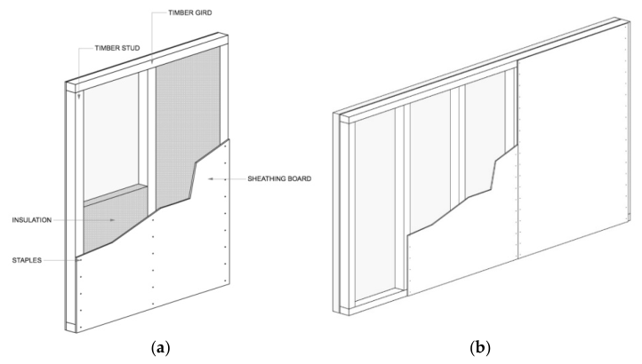
Frame–panel wall elements generally consist of frame members and sheathing panels, which are fastened to a timber frame, as shown schematically in
Figure 1. The load-bearing frame consists of joists and studs, which are typically spaced 62.5 cm apart due to the standard dimensions of the sheathing panels. Soft thermal insulation (rock or glass wool or blown-in cellulose insulation) is installed between the frame elements. The type of insulation selected depends primarily on the required ecological parameters and U-values and is not the subject of this study. More information on this can be found in [
1].
There are also various types of sheathing panels, such as OSB, gypsum board, and, more recently, gypsum fibre-plaster boards (FPB). The types of these elements significantly influence the fire and sound resistance of such wall elements [
1], as well as on the load-bearing capacity of the entire wall element under horizontal loads due to differences in the strength and stiffness of the sheathing material. We have already analysed this using the example of light timber-framed (LTF) wall elements in [
15,
16]. In this study, however, we pay special attention to the previously developed analyses [
12,
13,
14] of light steel-framed (LSF) wall elements and then compare them with our previous numerical studies on LTF elements [
15,
16].
Another important parameter is the spacing (
s) between the fasteners used to secure the sheathing panels to the frame elements. As part of our previous studies, we also investigated this parameter for interior and exterior LTF wall elements [
15,
16]. The studies showed that in this regard, the effect is significantly greater on LTF wall elements with OSB sheathing than on fibre-plaster sheathing material.
It is also important to specifically analyse both the interior and the additional top-layer-insulated exterior frame wall elements. Specifically, the thickness of the frame elements is significantly greater for exterior wall elements than for interior ones, typically in a ratio of 160 mm to 80 mm. We also numerically analysed how this increased thickness of LTF wall frame elements affects their horizontal load-bearing capacity and stiffness in [
15,
16]. It was demonstrated in both studies that for LTF elements, the difference in in-plane load-bearing stiffness is very low, between 2% and 4% only. Therefore, in this study, we analyse only the interior wall elements that were also experimentally tested in [
17].
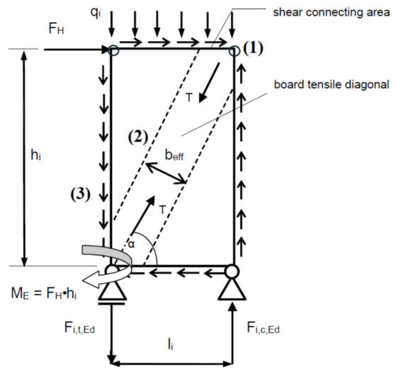
The frame elements independently carry the entire vertical load, first through bending in the beam element and then through axial compression in the frame columns, as schematically shown in
Figure 2. The sheathing panels do not contribute to the transfer of the vertical load.
In the case of horizontal load transfer, however, the situation is different, as the wall element acts as a two-dimensional in-plane composite element, since the horizontal load is first transferred via shear in the fasteners between the sheathing panel and the timber frame, and then through the tensile diagonal surface in the sheathing panel. This mechanism will be explained in more detail in
Section 2.2.
2.2. Load Transfer in Frame–Panel Wall Elements
To better understand the behaviour of a framed wall element, it is necessary to understand how vertical and horizontal loads are transmitted into the element. As mentioned before, vertical loads (qi) are transmitted exclusively through the frame elements, where the beams primarily bear the bending stresses and the columns bear the compressive stresses. This is not the focus of this study, as these are fairly trivial calculations.
In contrast, the transfer of forces due to a horizontal point load (
FH) at the top of the wall element with width (
bi) and height (
hi) is considerably more complex, as the load is first transferred via shear stress (1) in the connection plane between the sheathing and framing elements, and then via tensile force (
T) in the diagonal direction of the sheathing panel (2). Although the elements of the timber frame are structurally connected to one another with two 10 mm wood screws, in the structural analysis it is assumed that because of the deformability of the fasteners in timber, they are connected by hinged joints. This creates the so-called triangular transfer of force
FH, which ensures the static stability of the composite wall system. According to the scheme in
Figure 2, there also appear tensile (3) and compressive stresses in the studs of the frame.
Based on the above scheme, there are in general three possible theoretical failure modes for such a composite wall element:
Mode (1): Failure due to yielding of the mechanical fasteners in the connecting plane, also known as shear failure. This is typically the most ductile failure mode.
Mode (2): Failure in the tensile diagonal of the sheathing panel, considering the effective width of the tension zone beff = 0.2∙li. This is typically a very non-ductile failure mode.
Mode (3): Failure due to tensile forces in the timber-frame columns; however, this practically never occurs.
As we already demonstrated on the basis of extensive previous studies performed exclusively on LTF elements—both experimental [
17] and numerical [
15,
16]—Mode (1) almost always occurs in OSB sheathings due to its relatively high tensile strength. Conversely, in the case of FPB panels, where the tensile strength is approximately eight times lower than that of OSB panels, failure always occurs according to Mode (2). Failure according to Mode (3), however, occurred in our experimental tests [
17] only once, when we deliberately incorporated timber-frame elements with the lowest possible specified timber strength. Therefore, in practice, this type of failure practically never occurs and therefore will not be the subject of our further study.
2.3. Mathematical Modelling of Panel-Framed LTF and LSF Elements
There are generally two different methods for the mathematical modelling of LTF wall elements. Both follow the stress distribution as shown in the schematic diagram in
Figure 2 and the additional failure models presented in
Section 2. As is customary in practice when modelling such composite structural elements, there is a simplified calculation procedure that is also prescribed for engineering use in the valid Eurocode 5 standard [
18], and with additional expressions found in the drafts of the new Eurocode 5 standards [
19,
20]. Both include provisions based on a semi-analytical approach to the composite wall element in question. However, both semi-analytical methods are less accurate than the modelling method using finite elements and elastic springs, which approximate the slip deformability in the connection plane between the sheathing panel elements and the timber frame. Both modelling methods will be presented in more detail. However, none of these numerical approaches specifically address the case of light steel-framed (LSF) wall elements.
2.4. Semi-Analytical Approach (Shear Model)
The first semi-analytical approach, which is also prescribed by the currently valid Eurocode 5 standard [
18], is based on the shear failure model described in
Section 2—Mode (1). In this case, therefore, the failure criterion is the yielding of the fasteners between the sheathing panels and the timber-frame elements, as schematically shown in
Figure 2. Consequently, the characteristic horizontal load-carrying capacity of an individual LTF wall element (
Fi,v,Rk) is expressed as the sum of the lateral (Johansen) load-carrying capacity of a single fastener in this connection plane (
Ff,Rk), in the form of Equation (1):
where
b0 =
hi/2.
It is important to note, however, that the aforementioned method does not account for a potential Failure Mode (2) and is therefore practically applicable only to LTF elements with OSB sheathing, where this failure criterion cannot occur under any circumstances. We have already demonstrated this in several studies [
15,
16]. Additionally, it should be noted that the aforementioned method does not prescribe any expressions for calculating horizontal displacements and the resulting horizontal stiffness of the LTF wall element.
2.5. Semi-Analytical Approach (Composite Model)
In this case, the wall element is treated as a composite system using the cantilever element method, with a point horizontal force applied to its upper edge,
Figure 2. The element consists of a timber frame and a panel sheathing, which is connected to the timber frame with fasteners,
Figure 1. Since a slip deformation of the fasteners occurs in this connection plane, this must also be considered in the calculations using the so-called
γy coefficient taken from the valid Eurocode 5 standard [
18], which considers the flexibility of the fasteners in the form of:
The effective bending stiffness (
EIy)
eff and the shear stiffness (
GAs)
eff of mechanically jointed beams can therefore be written in the analytical form of:
It is important to note that this model also accounts for Failure Mode (2), which takes into account the possibility of tensile failure of the sheathing element. This is particularly important when using sheathings with low tensile strength, where shear failure does not occur at all. The tensile stress in the panel sheathing (
σt,0,d) can be calculated in the form of and must be lower than the design tensile strength (
σt,0,d <
ft,0,d) of the sheathing material:
with
My =
FH∙
hi. Lateral shear force acting on one fastener (
F1) in the connecting plane can be further developed in the form of:
We can find both expressions in the proposed new versions of the Eurocodes [
19,
20]. Additionally, the obtained numerical results were compared with our previous experimental studies in [
17]. It is important to note, however, that using the aforementioned semi-analytical method, we can account for Failure Mode (1) using Equation (4) in the case of shear yielding of the bonding agents in the connecting plane, or for Failure Mode (2) using Equation (3) in the case of tensile failure along the sheathing panel. In all of these studies, we also demonstrated that Mode (1) is typically decisive for OSB sheathing panels, while Mode (2) is decisive for fibre-plaster boards.
In addition, this method makes it very easy to calculate all horizontal displacements due to the bending (
uM) and shear deformation (
uV) of the panel, assuming that all supports of the wall element are completely stiff:
Additional horizontal displacements in all flexible support elements can be further considered using the expressions given in [
20,
21]. It is also important to note that the semi-analytical method described has so far been developed only for LTF elements; for LSF, this method can be used in calculation up to the
γy coefficient (Equation (2)) taken from the valid Eurocode 5 standard [
18]. For calculation of all horizontal displacements, this method is still in the development phase.
However, it should be noted that this relatively simple semi-analytical method has a significant limitation, namely, that the simple-beam theory using Bernoulli’s hypothesis is valid for each subcomponent. We know that this application of simple-beam theory using Bernoulli’s hypothesis is only accurate enough for cases where hi/bi is less than 2. When considering LTF elements, we are therefore at the limit of this validity. In this regard, scientific analyses require much more precise modelling of such composite wall elements using the FEM Spring model, which will be described in greater detail below.
2.6. FEM Spring Model
The applicability of this method to LTF or LSF wall elements is independent of whether the frame elements are made of timber or steel. The only difference is that in the case of LTF, the frame elements are modelled as orthotropic linear elements due to the characteristics of wood, whereas in the case of LSF, they are modelled as isotropic steel elements. In terms of simulating the distribution of horizontal force, as shown in
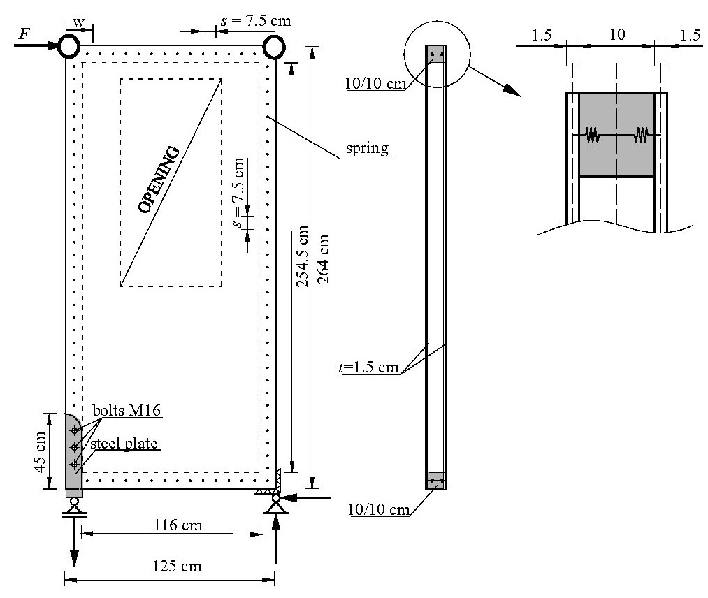
Figure 2, in both cases the in-plane load-bearing sheathing boards are modelled as 2D in-plane resisting isotropic shell elements. The point is that in this case we avoid using Bernoulli’s hypothesis, which we used in the semi-analytical procedures described above as the main and rather rough computational assumption. The connecting plane between the sheathing boards and frame elements is modelled by elastic spring elements where the lateral stiffness of the springs (
K) represents the slip modulus of the fasteners (
Kser). The distance between the elastic springs (fasteners) is marked as parameter
s in
Figure 3. Any window or door openings can be additionally considered. The only significant disadvantage of the FEM approach is that the distance between the connection elements (
s) must be considered in fully parametric calculations. In contrast, the semi-analytical approach considers (
s) in an analytical and fully continuous form, which is less accurate. Another limitation in terms of applicability is that the FEM model does not allow us to calculate the stiffness coefficient in the connection plane (
γy), nor does it allow us to calculate horizontal bending (
uM) and shear displacements (
uV) separately, as is possible using the semi-analytical approach in the composite model, see Equations (3a) and (3b). We can only calculate the total horizontal displacement at the top of the wall element. Therefore, the FEM method does not allow for a detailed analysis of the distribution of horizontal forces, as shown schematically in
Figure 2; such an analysis can only be performed by using the semi-analytical approach using Equations (2) and (3). The same statical model of the LTF and LSF elements is used according to the scheme presented in
Figure 3 for LTF and LSF wall elements.
We have already demonstrated the agreement between the numerical results for the in-plane stiffness of LTF elements using the semi-analytical approach and the FEM spring model in two previous numerical studies [
15,
16]. In both studies, we obtained very good agreement in the results for all parametrically selected spacing (
s) values between the fasteners and for both types of the sheathing boards.
3. Numerical Study
3.1. Test Specimens
In this study, only single-panel internal wall elements are considered in the systematic evaluation of the in-plane structural behaviour of lightweight framed systems under controlled and comparable conditions. The selection of internal wall configurations eliminates the influence of additional thermal insulation layers and external sheathing systems, thus allowing the mechanical response of the structural frame–sheathing interaction to be isolated and evaluated more precisely. The analysed wall elements follow the structural scheme and boundary conditions presented in
Figure 2, with overall dimensions of
l = 1250 mm and
h = 2640 mm, and corresponding internal dimensions of
li = 1160 mm and
hi = 2545 mm. These dimensions correspond to standard modular wall units commonly applied in prefabricated multi-storey timber construction.
The elements of two structural systems are investigated, namely, light timber-framed (LTF) and light steel-framed (LSF) elements. The LTF elements are modelled using timber of strength class C22 according to [
21] with cross-sectional dimensions of 100 × 100 mm, representing a typical internal wall configuration. The LSF elements are composed of cold-formed steel box sections with dimensions of 100 × 100 × 3 mm. Both systems are analysed under identical geometric and boundary conditions to ensure a consistent comparison of structural responses. The wall elements are symmetrically sheathed on both sides using either fibre-plaster boards (FPB) or oriented strand boards (OSB 3), each with a thickness of 15 mm. The selection of these materials enables the evaluation of the influence of sheathing stiffness and mechanical properties on the global response. Special attention is given to the distinction between these two sheathing materials, as previous studies [
15,
16] showed that their substantially different tensile and shear properties strongly influence the failure mode of frame–panel wall elements.
The material properties used in the analysis according to [
21] are summarised in
Table 1. As shown, steel exhibits significantly higher stiffness with the modulus of elasticity (
E0,mean) compared to timber, while FPB and OSB differ primarily in their shear modulus (
Gmean), which plays a crucial role in the in-plane behaviour of the wall elements. While there are significant differences in all strengths of the materials used, especially in terms of tensile strength (
ft,k) and bending strength (
fm,k), differences in the shear strength (
fv,k) and especially in the compressive strength (
fc,k) are not as obvious.
A key parameter considered in this study is the spacing between fasteners (s), which directly determines the degree of composite action between the sheathing and the frame. Four characteristic spacings were analysed: s = 37.5 mm, s = 75 mm, s = 150 mm and s = 300 mm. These values were selected to cover the full practical range typically used in contemporary prefabricated wall production and to allow a detailed evaluation of connection sensitivity. The selected spacing values also enabled a direct comparison between the semi-analytical approach and the FEM spring model. Although the semi-analytical formulation allows the evaluation of structural response for any fastener spacing within the investigated range, the FEM models were developed only for these four discrete fastening configurations. Consequently, the results presented in this study are limited to the selected spacing values, with the primary objective being the comparison of representative practical fastening layouts rather than a continuous parametric optimization of fastener spacing.
The mechanical behaviour of the sheathing-to-frame connection is defined through the slip modulus (Kser). For LTF elements, the sheathing boards are connected using staples of diameter dst = 1.53 mm and length lst = 35 mm, resulting in Kser,FPB = 295.218 N/mm and Kser,OSB = 194.028 N/mm. For LSF elements, when screws of diameter dsc = 5.5 mm and length lsc = 18 mm are used, a significantly higher stiffness is obtained, with Kser,LSF–FPB = 8136.15 N/mm and Kser,LSF–OSB = 7028.97 N/mm. The significantly higher slip modulus in LSF elements is a direct consequence of the greater stiffness of self-drilling screw connections in steel compared to those in stapled timber joints. This difference is expected to strongly influence the level of composite interaction and consequently the overall racking stiffness of the wall element.
All supports in this study are assumed to be fully rigid, and only bending, shear and sheathing-to-framing deformations are considered, according to the expressions in
Section 3.2. No vertical load is included, allowing a focused investigation of in-plane behaviour only. Excluding vertical load effects is justified by the objective of isolating the influence of horizontal load-transfer mechanisms, particularly the contribution of connection slip deformability, which is briefly described in
Section 3.2.
3.2. Results
The analysis of results focuses on the influence of three key parameters determining the in-plane response of lightweight framed wall elements: fastener spacing (s), type of sheathing material, and connection stiffness of a single fastener (Kser). Among these, particular emphasis is placed on the role of fastener spacing (s) as a primary parameter controlling the level of composite action.
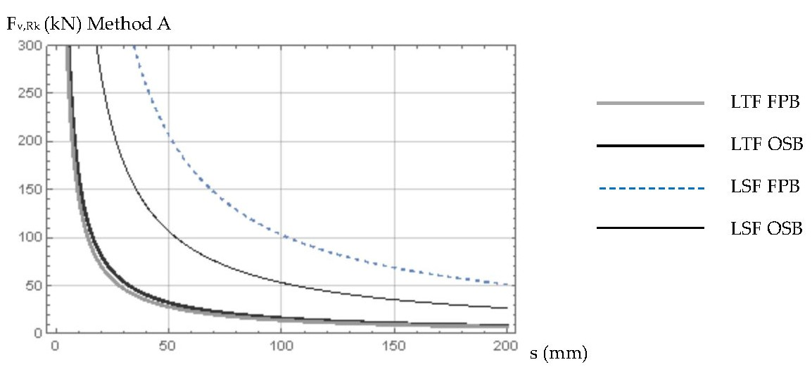
First of all, we can calculate the in-plane load-bearing capacity (
Fv,Rk) for all four types of analysed wall elements using Equation (1) in accordance with the valid Eurocode 5 standard [
18] using the semi-analytical approach with the previously described shear model (Method A). The results are presented in
Figure 4.
The results show that
Fv,Rk is significantly higher for LSF elements than for LTF elements. Similarly, for LSF elements, a significant difference is observed between FPB and OSB elements, and it should be emphasized that the values for FPB elements are significantly higher and that the difference increases as the distance between the fasteners (
s) decreases. In contrast, for LTF elements, the difference between FPB and OSB elements is less obvious, as we showed in detail in our previous studies [
15,
16].
Following the semi-analytical formulation presented in
Section 3, the shear stiffness coefficient (
γy) of the connecting plane was evaluated as a function of the fastener spacing (
s) using Equation (2). This coefficient represents the efficiency of interaction between the sheathing panels and the frame elements and directly affects both the effective bending stiffness (
EIy,eff) and the effective shear stiffness (
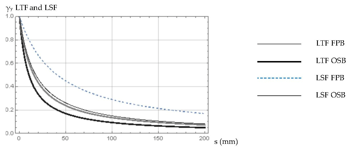
GAs,eff) of the wall element. As mentioned before, it is not possible to use this calculation with the FEM spring model. The results are plotted in
Figure 5.
As expected, increasing the fastener spacing (s) results in a reduction of γy, indicating weaker mechanical interaction between the sheathing and the frame members. Consequently, the wall element behaves less as an integrated composite system and more as a partially connected assembly. Additionally, the values are higher for LSF elements, especially when using FPB sheathings. Therefore, we can conclude that the sheathing-to-framing behaviour of LSF elements is much more pronounced than that of LTF elements.
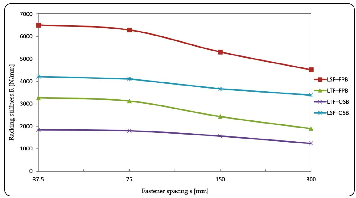
The obtained racking stiffness (
R) results obtained using the described FEM spring approach are presented in
Table 2 and graphically in
Figure 6, which illustrates the influence of the fastener spacing (
s) on the structural response of the analysed wall systems.
The structural response was evaluated under a horizontal load of
FH = 10 kN applied at the top of the wall element. The total horizontal displacement can be calculated only for the sum (
u =
uM +
uV), where
uM represents bending deformation and
uV shear deformation. As mentioned in
Section 2.6, it is not possible to calculate both deformations separately using the FEM model. The numerical results reveal several important structural trends.
4. Discussion
The results show a strong and systematic dependence of structural stiffness on fastener spacing. For all analysed configurations, increasing the spacing from 37.5 mm to 300 mm led to a significant reduction in racking stiffness. For example, in the LTF–FPB system the stiffness decreased by approximately 42%, while in the LSF–FPB system the reduction was only around 31%, clearly confirming the superior rigidity and connection efficiency of the steel-framed system. Similar trends are observed for OSB sheathing, although the absolute stiffness values are lower due to the substantially smaller shear modulus of OSB panels compared with FPB panels. This trend is particularly pronounced in LTF systems, where the lower slip modulus results in a more flexible connection and thus a greater sensitivity to changes in fastener spacing. In contrast, LSF systems exhibit a comparatively smaller reduction in stiffness due to their inherently higher connection rigidity, which maintains a higher level of composite action even at larger spacings.
Furthermore, the comparison between FPB and OSB sheathing reveals that FPB consistently provides higher stiffness across all spacing configurations. This behaviour is primarily attributed to the significantly higher shear modulus of FPB boards, which increases the contribution of the sheathing to the overall in-plane resistance. However, based on the failure criteria described in
Section 2, it should be noted that FPB systems remain governed by tensile failure of the sheathing diagonal (Mode 2), while OSB systems are predominantly governed by the shear yielding of fasteners (Mode 1) [
15,
16]. However, the relative difference between the two materials becomes more pronounced at larger fastener spacings, where the influence of connection flexibility is amplified.
The FEM analysis was performed in SAP2000 [
22] using a representative spacing of
s = 75 mm for LTF elements only, and it shows good agreement with the semi-analytical [
15,
16] and experimental [
17] results, confirming the validity of the semi-analytical approach. The deviation between both methods remained within an acceptable engineering tolerance, confirming that the simplified semi-analytical model is sufficiently accurate for practical design applications, especially during preliminary dimensioning and optimization studies. Nevertheless, as also noted in [
15], the FEM spring model does not allow a direct parametric variation of fastener spacing, which highlights the advantage of the semi-analytical approach for sensitivity analyses. Overall, the results clearly demonstrate that fastener spacing (
s) is one of the most influential design parameters, directly affecting the stiffness, deformation behaviour, and efficiency of composite action in both LTF and LSF wall systems. These findings are fully consistent with the conclusions reported in [
15] for LTF elements and further emphasize the importance of optimizing connection layout in practical design. The analysed spacing range does not alter the governing failure mechanism of the investigated wall systems. OSB-sheathed wall elements remain governed by fastener yielding (Mode 1), whereas FPB-sheathed wall elements remain governed by tensile failure of the sheathing diagonal (Mode 2). Increasing fastener spacing primarily reduces composite action and stiffness, resulting in the governing failure criterion being reached at lower load levels.
From a practical design perspective, the results indicate that LSF wall elements can provide a highly effective strengthening solution for lower storeys of four- to five-storey timber buildings with increased torsional effects due to asymmetrical glazing or irregular floor plans. Their significantly higher stiffness and reduced sensitivity to fastener spacing make them particularly suitable for stabilizing wall elements in light frame–panel systems while maintaining thermal performance comparable to conventional LTF walls. Consequently, the combined use of conventional LTF wall elements in upper storeys and strategically positioned LSF strengthening panels in lower storeys appears to be a rational and economically justified design strategy for mid-rise timber buildings subjected to increased horizontal actions. It should be noted that the stiffness values presented in this study correspond to monotonic loading conditions and therefore represent the initial stiffness of the wall systems. Under cyclic seismic loading, stiffness degradation is expected due to progressive slip and local damage in the sheathing-to-frame connections. Nevertheless, the influence of fastener spacing observed in the present study is expected to remain qualitatively similar, since connection deformability remains the governing parameter in both loading scenarios.
5. Conclusions
This study presents a comparative numerical investigation of the in-plane structural behaviour of light timber-framed (LTF) and light steel-framed (LSF) wall elements subjected to a point horizontal load at the top of the wall element. Attention is given to the influence of fastener spacing, sheathing material, and connection stiffness on the global racking stiffness and composite action of frame–panel wall systems. The analyses are performed using both a semi-analytical shear model, used for the load-bearing capacity and shear stiffness coefficient in the connecting plane, and a more accurate FEM spring model, enabling a comprehensive evaluation of the governing deformation mechanisms and load-transfer behaviour. The performed numerical analyses clearly show that fastener spacing is one of the most influential parameters affecting the in-plane stiffness behaviour of both LTF and LSF wall elements. Increasing the spacing between fasteners consistently reduced the level of composite interaction between the sheathing and the frame, resulting in lower racking stiffness and increased horizontal displacements. This effect was especially pronounced in LTF wall systems, where the relatively lower slip modulus of the sheathing-to-frame connections led to greater sensitivity to connection deformability.
The results further show that LSF wall elements exhibited significantly higher racking load-bearing capacity and stiffness than the corresponding LTF elements for all analysed fastening layouts and sheathing configurations. This behaviour can primarily be attributed to the substantially higher elastic stiffness of steel frame members, along with the considerably higher stiffness of the sheathing-to-steel connections. Consequently, LSF wall systems maintained a higher degree of composite action even at larger fastener spacings. A comparison between different sheathing materials also revealed that fibre-plaster board (FPB) sheathing consistently provided higher global stiffness than OSB sheathing in both framing systems. This behaviour is mainly related to the higher shear modulus of FPB panels, which increases the in-plane shear stiffness of the composite wall element. However, the numerical analyses also confirmed significantly different dominant failure mechanisms of the investigated systems. In agreement with previous experimental and numerical studies, failure in OSB-sheathed wall elements occurred primarily due to yielding of the fasteners in the connection plane (Mode 1), whereas FPB systems failed predominantly due to tensile rupture along the sheathing diagonal (Mode 2). The comparison between the semi-analytical approach and the FEM spring model showed very good agreement in the predicted stiffness behaviour and deformation response. The results confirm that the semi-analytical composite model is sufficiently accurate for engineering applications and preliminary design procedures, while the FEM spring model is more suitable for advanced scientific analyses and detailed parametric investigations.
From a practical design perspective, the findings demonstrate that LSF-strengthened wall elements are a highly efficient solution for improving the global horizontal stiffness of multi-storey timber buildings, particularly in lower stories subjected to increased wind- and earthquake-induced torsional effects caused by asymmetrical floor plans or glazing layouts.
From the perspective of Eurocode 5 design, the results confirm the importance of connection deformability as a key parameter influencing the serviceability behaviour of timber-based shear walls. The observed stiffness reductions of approximately 31–42% when fastener spacing increased from 37.5 mm to 300 mm demonstrate that fastener layout should be considered a primary design variable rather than merely a detailing requirement. For practical applications, spacing values not exceeding 75–150 mm provide a favourable balance between stiffness, constructability, and fastening effort, whereas larger spacings result in disproportionately large reductions in racking stiffness. Furthermore, the results indicate that strategically positioned LSF wall elements may significantly enhance the lateral stiffness of lower storeys in mid-rise timber buildings, thereby complementing existing Eurocode-based design approaches for lateral load-resisting systems.
Finally, it should be emphasized that this study was limited to single-panel wall elements subjected only to horizontal loading, without the influence of vertical compressive forces. Future research should focus on experimental and numerical investigations of complete multi-storey wall assemblies, including cyclic and seismic loading conditions, uplift effects, and the interaction between vertical and horizontal load-transfer mechanisms.