Abstract
Fast-growing hardwoods like poplar often lack natural durability in outdoor use and require homogeneous impregnation with protective agents, though achieving homogeneity remains a known challenge. Various anatomical structures influence fluid transport in wood. This study compares characteristics of pits in libriform fibres, between ray–vessel interfaces, and between vessel-to-vessel connections in normal wood and tension wood of a hybrid poplar genotype (Populus × canadensis, ‘Gelrica’), including both impregnated (with an aqueous, dye-containing solution) and non-impregnated regions, to identify anatomical barriers to impregnation. Light and scanning electron microscopy revealed significant differences in pit morphology and frequency in libriform fibres between normal wood and tension wood. In non-impregnated regions, pits were often encrusted. Vessel–ray pits did not differ between normal wood and tension wood but showed distinct differences between impregnated and non-impregnated regions: in the latter, pits were occluded by tylose-forming layers. Intervessel pits differed in border and aperture size between earlywood and latewood in both normal wood and tension wood. Hence, fluid transport is strongly impeded by occluded vessel–ray pits and, to a lesser extent, by encrusted fibre pits.
1. Introduction
Fast-growing hardwood species are gaining increasing importance from both economic and research perspectives. However, their practical use in outdoor applications is often limited by low natural durability to biological degradation [1,2]. To ensure sufficient durability, effective and homogeneous impregnation with wood preservatives or chemical modification agents is essential [3,4]. In practice, fast-growing hardwoods, such as poplar, frequently exhibit limited and inhomogeneous penetration and distribution of such agents within the wood matrix (Figure 1) [5,6,7,8,9]. Studies on Gmelina arborea have shown that impregnation is even next to impossible [10,11]. A recent study demonstrated the inhomogeneous distribution of liquids among different genotypes of Populus × canadensis, with non-impregnated regions occurring particularly within the transition zone at the sapwood–heartwood boundary [12]. The underlying cause of this phenomenon, which has also been reported in other studies [6,7,8], has not yet been fully identified, although it is evidently related to the microstructure of poplar wood [13,14]. In comparison with softwoods, the anatomical structure of hardwoods [15] and the associated fluid transport pathways are significantly more complex [16,17]. This increased complexity is primarily attributable to the more heterogeneous cellular composition that characterises hardwood anatomy. In fast-growing hardwoods with low natural durability, irregular fluid uptake may contribute to a reduced service life in exterior applications. This highlights the necessity for further investigations into the underlying anatomical causes of inhomogeneous impregnation, with the aim of improving the understanding of fluid transport processes and their structural determinants [12].
The term liquid permeability refers to the extent to which wood can absorb and transport fluids. It is a physical parameter that characterises the capacity of a porous medium to allow fluid movement under the influence of a pressure gradient [13,18,19]. The main structural elements that influence the permeability of hardwoods are vessels (diameter, length, frequency, distribution), radial pits (type, size), and extractive content [20]. Other anatomical elements, including the lumen diameter of fibres and parenchyma cells, the frequency of individual cell types, as well as the number and size of tangential pits, play a secondary role [13,16,21,22]. In addition, the formation of tyloses within the vessels of hardwoods can significantly reduce the axial permeability of the wood by obstructing the longitudinal pathways for fluid movement [13,23,24,25].
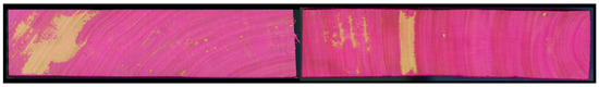
Figure 1.
Representative images illustrating heterogeneous distribution patterns in poplar wood impregnated with an aqueous, dye-containing solution [26].
Another potential factor that has so far been insufficiently investigated could be reaction wood. Tension wood (TW), as a type of reaction wood only occurring in hardwoods, is frequently observed in fast-growing hardwood species [27]. TW is characterised by the thickening of fibre walls through the formation of a gelatinous layer (G-layer), predominantly composed of cellulose [28,29]. Recent studies by Buschalsky et al. [12,26] found a significant presence of TW areas in Populus × canadensis, but their influence on impregnability could not be conclusively determined. However, studies have shown that the high fibre content and abundant mesopores in TW do not significantly increase permeability [30]. Furthermore, fungal degradation of the G-layer does not lead to improved permeability. Therefore, radial permeability in TW is primarily influenced by ray–vessel and intervessel pits in TW [9]. Investigations on beech wood (Fagus sylvatica L.), as a non-fast-growing hardwood species, revealed that the radial air permeability of TW is reduced in comparison to normal wood (NW). This reduced permeability is assumed to be caused by a lower number and smaller diameter of intervessel pits [31,32]. Studies on poplar (Populus nigra) have shown no differences between NW and TW with respect to the diameter and frequency of intervessel and vessel–ray pits [33].
Due to the limited availability of research data, this study aims to compare pit characteristics (number, dimensions, and morphology) between TW and NW in a hybrid poplar genotype. To enable a comprehensive analysis, both impregnated and non-impregnated regions from the transition zone at the sapwood–heartwood boundary were examined, as this area in particular has been identified as a refractory zone in previous studies on poplar. The investigation considered ray–vessel interfaces (vessel–ray pits), vessel-to-vessel connections (intervessel pits), and libriform fibres. The objective is to identify anatomical differences between TW and NW, as well as between impregnated and non-impregnated regions, which may affect permeability.
2. Materials and Methods
This study used hybrid poplar stem sections (Populus × canadensis, ‘Gelrica’, Moench) originating from 25- to 28-year-old plantation-grown trees cultivated in the Netherlands (n = 4). A comprehensive description of the wood material can be found in the study by Buschalsky et al. [12]. For the investigations, air-dried boards were impregnated after reaching treatability (moisture content < 20%) with a dye-containing aqueous solution (0.05% rhodamine B) using a 2 h vacuum followed by 5 h of pressure at 1 MPa. The light red hue of rhodamine B allows for macroscopic and microscopic visualisation of the distribution of the absorbed impregnation solution within the wood. This allows both impregnated and non-impregnated regions to be identified.
For microscopic analysis, TW and NW areas were extracted from the transition zone at the boundary between sapwood and heartwood. One central board was used from each stem section. The extensive presence of TW was macroscopically identifiable based on the woolly surface texture of the specimens (Figure 2a,b) and was used for preliminary sample selection. The occurrence of tension wood within the samples was subsequently evaluated using the safranin/Astra blue staining method (see below). From both areas (TW and NW), specimens (n = 5) encompassing entire annual rings, including both upper and lower ring boundaries, were prepared from impregnated and non-impregnated areas, respectively. After 24 h water storage, cross-sectional thin sections (15 µm) were prepared using a sliding microtome from every specimen. To differentiate between TW and NW, the thin sections were stained with safranin and Astra blue according to Gerlach [34]. Safranin stains the lignin in lignified cell walls red, while Astra blue stains cellulose blue. Prior to staining, the sections were decolourised by immersion in 70% ethanol to remove residual rhodamine B. This step ensured that only areas predominantly composed of TW or NW were selected for the subsequent pit analysis. Figure 2b shows an exemplary NW region of a specimen, while Figure 2c depicts a TW region.
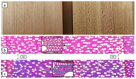
Figure 2.
Overview of specimen selection: (a,b) Comparison of specimens with a smooth surface (left) and a “woolly” surface (right). The woolly surface serves as a macroscopic indicator for tension wood (TW). Light microscopic images of (b) an annual ring from an area of normal wood (NW), and (c) an annual ring from an area of tension wood (TW). Safranin stains the lignin in lignified cell walls red, while Astra blue stains cellulose blue. Since the distinctive G-layer of TW consists primarily of cellulose, TW areas can be identified by their blue staining, whereas NW areas appear red. The inset squares show magnified views of NW and TW fibres.
For the examination of pit characteristics, radial thin sections (15 µm) were prepared from the aforementioned different specimens from earlywood (EW) and latewood (LW) regions. The sections were prepared at sample positions located near the annual ring boundaries. The respective positions for both EW and LW are exemplarily indicated in Figure 2b,c. From each specimen, 5 thin sections were prepared, and for each thin section, 10 grids were evaluated (Figure 3). The specimens were examined using a transmitted light microscope (TLM) of the type BZ-X810 (Keyence Deutschland GmbH, Neu-Isenburg, Germany) as well as a scanning electron microscope (SEM) of the type EVO LS 15 (Carl Zeiss Microscopy GmbH, Oberkochen, Germany). The following subsections describe the methodologies applied for the different cell types.
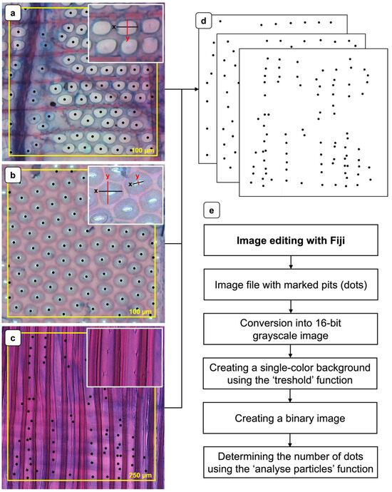
Figure 3.
Methodology for assessing pit frequency and dimensions using representative light microscopy images: (a) Radial section showing pitting at the interface between a ray cell and a vessel (vessel–ray pits). (b) Radial section showing intervessel pitting. (c) Radial section showing pits of libriform fibres. The yellow square boxes (a–c) illustrate representative analysis areas, each corresponding to a grid with an edge length of 100 or 250 µm. (d) Representative binary images for determining the pit frequency (black dots). (e) Flowchart of the image editing procedure.
2.1. Vessel–Ray Pits and Intervessel Pits
Pit frequency [n 100 µm−2] was assessed on safranin/Astra blue-stained radial thin sections (15 µm) using the TLM equipped with a 40× objective lens. Representative images of vessel–ray pits and intervessel pits are presented in Figure 3a and Figure 3b, respectively. To facilitate quantification, a 100 µm × 100 µm square grid was overlaid on the micrographs, and all pits within the defined area were manually marked (black dots) using the microscope software BZ Series Application (01.02.03.02). The resulting images were exported in TIFF format and further processed to binary images (Figure 3d) and subsequently analysed with the image analysis software Fiji (2.16.20/1.54p) [35]. The image processing is shown schematically in Figure 3e.
Pit dimensions were determined using the TLM at 100× objective magnification by performing orthogonal measurements (x and y) of pit length and width (see magnified sections in Figure 3a,b). For intervessel pitting, both the pit apertures and the surrounding pit borders were measured.
2.2. Pits of Libriform Fibres
The determination of pit frequency in libriform fibres [n 250 µm−2] was carried out according to the methodology described above for vessel–ray and intervessel pits (Figure 3c). Although fibre pits could be identified using TLM, their dimensions were difficult to measure reliably, necessitating analysis via SEM. For this purpose, samples from the NW and TW regions were mounted on aluminium stubs (Plano GmbH, Wetzlar, Germany). Subsequently, the stubs were placed in a sputter coater of the type SC7620 (Quantum Design GmbH, Darmstadt, Germany) and made electrically conductive by coating with gold/palladium for 120 s at a plasma current of 18 mA. This coating time resulted in an approximate layer thickness of 10 nm. Focused electron images of the investigated sample areas were generated and saved using the following SEM parameters: accelerating voltage = 3–6 kV; probe current = 10–150 pA; working distance = 2.5–10 mm; OptiBeam Mode = Depth.
2.3. Statistics
A one-way analysis of variance (ANOVA) was conducted to identify significant differences in pit frequency and pit dimensions (significance level α = 0.05) among the different cell types, considering the EW and LW of both NW and TW. For pit dimensions, x- and y-values were analysed separately and compared independently.
3. Results and Discussion
3.1. Vessel–Ray Pits
The frequency of vessel–ray pits was quantified by comparing NW and TW, with further differentiation between EW and LW (Figure 4a). While the mean frequency for NW (EW: 71 ± 11; LW: 69 ± 12) is slightly higher compared to TW (EW: 67 ± 13; LW: 67 ± 12), the difference was not statistically significant. Similarly, no significant differences in mean pit dimensions NW (EW: x = (8.8 ± 0.9) µm, y = (7.0 ± 0.9) µm; LW: x = (8.7 ± 0.9) µm, y = (6.8 ± 0.7) µm) and TW (EW: x = (8.5 ± 1.1) µm, y = (6.9 ± 0.7) µm; LW: x = (8.4 ± 0.7) µm, y = (6.8 ± 0.7) µm) were observed (Figure 4b). These results align with those of Emaminasab et al. [33], who also reported no significant differences in vessel–ray pit frequency or dimensions between NW and TW in poplar wood. Accordingly, for these two parameters, no impact on wood impregnability could be inferred.
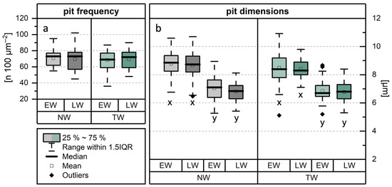
Figure 4.
Results of the investigation of pit characteristics within the contact areas between wood rays and vessels (vessel–ray pits). Comparison of (a) pit frequency, and (b) pit dimensions between normal wood (NW) and tension wood (TW). The methodology for determining the x- and y-dimensions is shown in Figure 3a.
However, the comparative examination of pits in impregnated and non-impregnated regions revealed distinct differences. In impregnated regions, the pits appeared freely permeable, as they were not occluded. This can be seen in both the TLM (Figure 5a,b) and the SEM (Figure 5g,h) images. In contrast, the apertures of pits in non-impregnated regions are occluded. Blue staining of these occlusions with Astra blue indicated that they are composed of a cellulose-based substance (Figure 5c,d). Figure 5e shows occluded vessel–ray pits and a blue-stained structure identified as a tylose. Figure 5f supports this interpretation by presenting tyloses within vessels in cross-section. These structures are also composed of cellulose, as indicated by the staining. The SEM images in Figure 5i,j further illustrate that almost all pits are occluded. Residues of tylosis structures are also visible in these images (yellow arrows). The mechanism of tylosis formation was comprehensively described in the review paper by De Micco et al. [36]. Tyloses are predominantly formed in parenchyma cells of wood rays that are adjacent to a vessel. From these contact cells, a special cell wall layer develops, which extends over the portions of the cell wall that are in contact with the vessel [37,38,39,40]. This so-called ‘protective layer’ or ‘tylose-forming layer’ is primarily composed of pecto-cellulose [38] and serves as a physical barrier against the swelling of parenchyma cells [39].
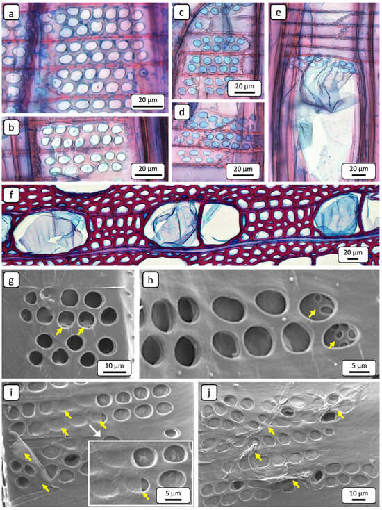
Figure 5.
Representative TLM (a–f) and SEM (g–j) images for characterising vessel–ray pits: (a,b) Radial section showing non-occluded pits of an impregnated area. (c,d) Radial section showing occluded pits of a non-impregnated area. The Astra blue staining clearly indicates that the occlusion consists of a cellulose-based substance. (e) Radial section showing occluded pits of a non-impregnated area. A tylose is visible, which is also composed of cellulose. (f) Cross-sectional image demonstrating that the blue-stained tyloses are composed of cellulose. (g,h) Radial section showing non-occluded pits of an impregnated area. Through the pit apertures, inter-ray pits are visible (yellow arrows). (i,j) Radial section showing predominantly occluded pits in a non-impregnated area. The pits are partially covered by residues of tylosis material (yellow arrows).
Once the hydrostatic pressure exceeds a critical threshold and the cell wall layer can no longer resist the osmotic pressure of the parenchyma cells, it bulges through the vessel–ray pits into the vessel lumen, resulting in the formation of tyloses [39,41]. A recent study demonstrated that the proportion of tyloses was significantly higher in non-impregnated regions compared to impregnated ones [12]. The pecto-cellulosic composition of the protective layer is consistent with the staining of the pit occlusions with Astra blue. Given the high prevalence of tyloses, it can be assumed that the occluded vessel–ray pits in the non-impregnated regions constitute the physical barrier formed by the protective layer. In the radial direction, the parenchyma cells of the wood rays are generally considered to play a major role in fluid transport [16,22]. However, these pathways are interrupted by the end walls of the parenchyma cells, which are further characterised by small inter-ray pits (Figure 5g,h; yellow arrows) [42,43]. In poplar, the predominantly uniseriate wood rays are connected to adjacent vessels via large vessel–ray pits (Figure 5). Consequently, it is more likely that fluids are redirected into adjacent vessels over short distances through ray cells rather than being transported through the entire wood ray [33]. If the vessels in non-impregnated regions are occluded by tyloses and, in addition, the vessel–ray pits are blocked by the protective layer, the redirection of fluid flow through the wood rays to adjacent vessels is no longer possible.
3.2. Intervessel Pits
The frequency of intervessel pits was quantified by comparing NW and TW, with further differentiation between EW and LW (Figure 6a). The mean pit frequencies for NW (EW: 56 ± 12; LW: 54 ± 9) and TW (EW: 56 ± 8; LW: 55 ± 11) are comparable, and no statistically significant variations were identified. Comparing the dimensions of the pit borders (Figure 6b), differences between NW and TW were observed in x- and y-dimensions, respectively. Pit borders in TW were smaller in both directions, for both EW (x = (10.1 ± 0.8) µm, y = (8.9 ± 0.7) µm) and LW (x = (8.7 ± 1.1) µm, y = (8.2 ± 0.8) µm) compared to NW (EW: x = (10.9 ± 1.2) µm, y = (9.0 ± 0.9) µm; LW: x = (9.9 ± 1.2) µm, y = (8.7 ± 0.8) µm). Although the differences were relatively small, they were statistically significant according to the ANOVA. Comparing the dimensions of the pit apertures between NW and TW (Figure 6c), statistically significant differences were found only in the x-dimensions within EW. These findings contrast with those reported for Populus nigra [33], where no significant differences in average intervessel pit diameter were observed. However, the results regarding pit frequency are consistent. Studies on Fagus sylvatica [32,44] showed that the intervessel pits in TW are significantly smaller compared to NW. Nevertheless, the differences reported in the cited studies were substantially greater than those observed in the present investigation.
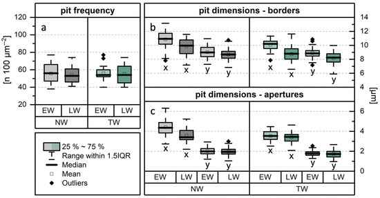
Figure 6.
Results of the analysis of intervessel pit characteristics. Comparison of (a) pit frequency, (b) dimensions of pit borders, and (c) dimensions of pit apertures between normal wood (NW) and tension wood (TW). The methodology for determining the x- and y-dimensions is shown in Figure 3b.
Moreover, significant differences in both dimensional parameters were observed comparing EW (Figure 7a–c) and LW (Figure 7d). The most pronounced differences occurred in the x-dimensions of the pit borders (Figure 6b) in both NW and TW (see values in the previous paragraph), as well as in the pit apertures (Figure 6c) of NW (EW: x = (4.4 ± 0.8) µm; LW: x = (3.6 ± 0.7) µm). Differences in the size of bordered pits between EW and LW have previously been described for tracheids in softwoods [45]. The present findings confirm that these differences also apply to vessels in Populus × canadensis. This suggests that the vessels in EW are more permeable than those in LW because intervessel pits are the main pathways for fluid movement between vessel elements. In this context, the structure and frequency of the pits are particularly important [46].
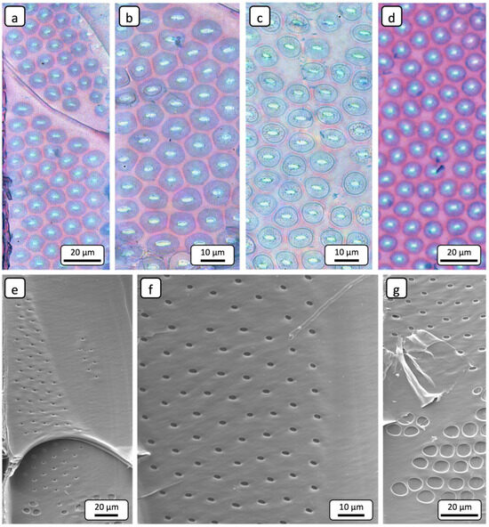
Figure 7.
Representative TLM (a–d) and SEM (e–g) images for characterising intervessel pits: (a) Radial section showing intervessel bordered pits in earlywood. (b) Pits at higher magnification. The focal plane was adjusted to provide a top-down view of the pit borders. (c) The focal plane is adjusted to allow visualisation of the inner structure of the pit borders. (d) Radial section showing bordered pits in latewood. (e,f) Radial sections showing pits at different magnifications. Pit borders are not visible under the applied SEM imaging parameters. (g) Tylose residue partially covering several of the intervessel pits in a non-impregnated area. Vessel–ray pits are occluded.
3.3. Pits in Libriform Fibres
The frequency of pits in libriform fibres was quantified by comparing NW and TW, with further differentiation between EW and LW (Figure 8a). The mean frequency in NW (EW: 90 ± 25; LW: 92 ± 29) was significantly higher—approximately twice as high—compared to that observed in TW (EW: 54 ± 15; LW: 46 ± 17).
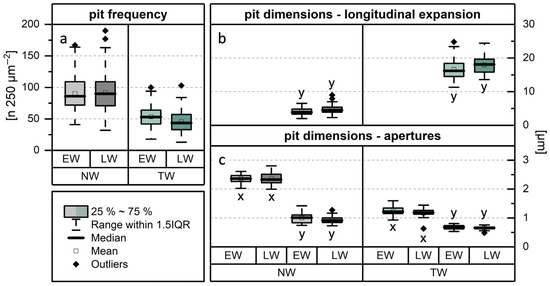
Figure 8.
Results of the analysis of pit characteristics in libriform fibres. Comparison of (a) pit frequency, (b) longitudinal expansion of pits, and (c) dimensions of pit apertures between normal wood (NW) and tension wood (TW).
Regarding pit morphology, TLM (Figure 9a) and SEM (Figure 9c–f) images showed that NW fibres have simple, slit-like pits. In contrast, pits in TW fibres (EW: (16.6 ± 2.8) µm; LW: (17.9 ± 2.6) µm) are significantly more elongated (Figure 9b,i,j), exhibiting a longitudinal expansion more than four times greater than that of pits in NW fibres (EW: (4.0 ± 1.0) µm; LW: (4.6 ± 1.3) µm) (Figure 8b). The significantly greater pit elongation in TW suggests that fewer pits occur per area compared to NW, which provides a plausible explanation for the observed differences in pit frequency.
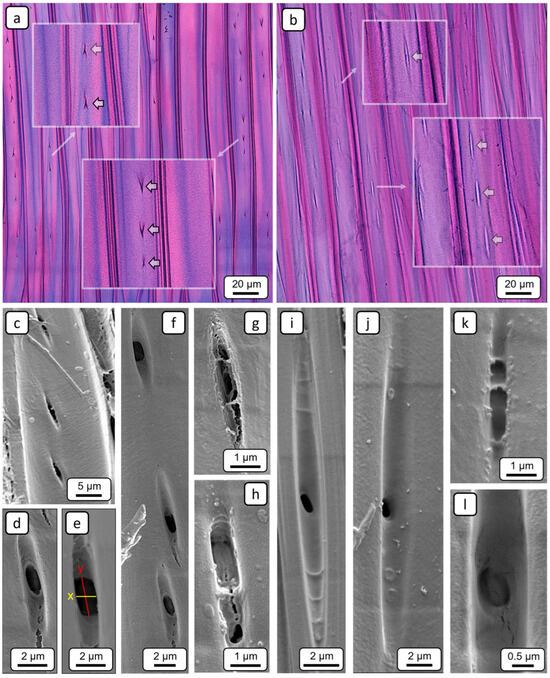
Figure 9.
Representative TLM (a,b) and SEM (c–l) images for characterising pits in libriform fibres. Radial sections showing pits (a) in normal wood, and (b) in tension wood; the inset squares show magnified views of the pits (bold arrows). (c–f) Slit-like pits in normal wood. (g,h) Encrusted pits in normal wood from a non-impregnated area. (i,j) Pits in tension wood that are significantly more elongated compared to those in normal wood. (k,l) Encrusted pits in tension wood from a non-impregnated area.
Furthermore, differences in aperture size were observed (Figure 8c). The results of the orthogonal measurements revealed that the transversal diameter (x-dimensions) of the apertures in NW fibre (EW: (2.4 ± 0.2) µm; LW: (2.4 ± 0.3) µm) pits is significantly larger—approximately twice as high—than that in TW fibre pits (EW: (1.2 ± 0.2) µm; LW: (1.2 ± 0.2) µm). In contrast, the longitudinal diameter (y-dimensions) exhibited only minor differences. Consequently, the pits in NW and TW fibres can be clearly distinguished based on their morphology. For Populus nigra, similar descriptions of pronounced morphological differences between the pits of NW and TW fibres have been reported, with the latter being oriented in the direction of the microfibrils [33].
In addition to fibre pits with clearly identifiable apertures, pits lacking a well-defined or even completely absent aperture were also observed in non-impregnated regions, in both NW (Figure 9g,h) and TW (Figure 9k,l). These pits appear to be partially or completely occluded by a substance. Similar observations of pit encrustations have been reported in hardwoods [47,48], including poplar [6]. The exact composition of these encrustations has not yet been conclusively determined. It is evident that encrustation of fibre pits results in a reduction in permeability. However, given the substantially higher permeability of vessels compared to fibres [42], caused by their numerous inter- and intravessel pits, the overall impact of such fibre pit encrustations on total wood permeability is likely to be negligible.
4. Conclusions
The study confirmed previously reported distinctive anatomical differences between libriform fibres in normal and tension wood, while providing more detailed characterisations based on high-resolution microscopic imagery. Scanning electron microscopy revealed fibre pit encrustations in non-impregnated regions of both normal wood and tension wood.
As a novelty of the study, both the pit frequency and the size of the pit apertures of libriform fibres were compared between the two wood structures. The results showed that tension wood exhibited nearly half the pit frequency of normal wood, and the transverse aperture diameters were approximately 50% smaller in tension wood. The combination of lower pit frequency and smaller aperture size suggests a reduced radial permeability of tension wood compared to normal wood. However, the overall impact of both the morphological differences between normal wood and tension wood and the encrustations of fibre pits on the overall radial permeability is likely to be negligible.
In agreement with previous studies, no significant differences were found between vessel–ray pits comparing normal wood and tension wood. However, as a key finding of the study, pit occlusions of vessel–ray pits, which are predominantly composed of cellulose-based material, were observed in non-impregnated regions, presenting a distinct physical barrier. In addition to the significantly reduced axial permeability of vessels due to tylose formation reported in earlier studies, fluid transport via the large vessel–ray pits and the parenchyma cells of the wood rays to adjacent vessels is not possible in non-impregnated areas.
Regarding intervessel pits, significant differences in pit dimensions were observed when comparing earlywood and latewood within both normal wood and tension wood, suggesting that the vessels in earlywood are more permeable than those in latewood. This observation has been well documented for softwoods, but has only been sporadically reported for hardwoods.
Author Contributions
Conceptualisation, A.B. and T.K.; methodology, A.B.; formal analysis, A.B. and T.K.; investigation, A.B.; data curation, A.B.; writing—original draft preparation, A.B.; writing—review and editing, H.M. and T.K.; visualisation, A.B.; project administration, H.M. and T.K.; funding acquisition, H.M. and T.K. All authors have read and agreed to the published version of the manuscript.
Funding
This article was funded by the German Research Foundation (DFG) (grant number: 275616905).
Data Availability Statement
The original contributions presented in this study are included in the article. Further inquiries can be directed to the corresponding author.
Acknowledgments
The authors gratefully acknowledge the Dutch timber merchant JF van Boeckel for providing and supplying the test material, as well as Britt Janßen and Caroline Marie Christine Caesar for their practical assistance with the light microscopic investigations. This article is a revised and expanded version of a conference paper entitled ‘Vergleich der Tüpfelcharakteristika zwischen Zug- und Normalholz bei Pappel (Populus × canadensis, Moench)’, which was presented at 6. Holzanatomisches Kolloquium, Dresden, Germany, 7–8 November 2024.
Conflicts of Interest
The authors declare no conflicts of interest.
Abbreviations
The following abbreviations are used in this manuscript:
| NW | normal wood |
| TW | tension wood |
| EW | earlywood |
| LW | latewood |
| TLM | transmitted light microscope |
| SEM | scanning electron microscope |
References
- Eriksson, K.-E.L.; Blanchette, R.A.; Ander, P. Microbial and Enzymatic Degradation of Wood and Wood Components; Springer Series in Wood Science; Springer: Berlin/Heidelberg, Germany, 1990; ISBN 978-3-642-46689-2. [Google Scholar]
- Wood and Tree Fungi: Biology, Damage, Protection, and Use; Schmidt, O., Ed.; Springer: Berlin/Heidelberg, Germany, 2006; ISBN 978-3-540-32138-5. [Google Scholar]
- Tsoumis, G. Science and Technology of Wood: Structure, Properties, Utilization; Reprint of the ed. New York 1991; Verlag Kessel: Remagen-Oberwinter, Germany, 2009; ISBN 978-3-941300-22-4. [Google Scholar]
- Van Acker, J.; Van Den Bulcke, J.; Forsthuber, B.; Grüll, G. Wood Preservation and Wood Finishing. In Springer Handbook of Wood Science and Technology; Niemz, P., Teischinger, A., Sandberg, D., Eds.; Springer Handbooks; Springer International Publishing: Cham, Germany, 2023; pp. 793–871. ISBN 978-3-030-81314-7. [Google Scholar]
- De Boever, L.; Van Acker, J.; Vansteenkiste, D.; Stevens, M. Preservative Treatment of Willow Wood (Salix Alba): Product Retention and Spatial Distribution. Wood Res. 2008, 53, 29–41. [Google Scholar]
- Murphy, R.J.; Din, S.U.; Stone, M.J. Observations on Preservative Penetration in Poplar. In Proceedings of the Proceedings IRG Annual Meeting, Kyoto, Japan, 20–24 May 1991; p. 7, IRG/WP 3662. [Google Scholar]
- Van Acker, J.; Stevens, M.; De Haas, C. Influence of Clonal Variability on the Impregnability of Poplar Hybrids. In Proceedings of the Proceedings IRG Annual Meeting, Rotorua, New Zealand, 13–19 May 1990; p. 8, IRG/WP 3614. [Google Scholar]
- Van Acker, J.; Stevens, M. Investigation into the Heterogeneous Nature of the Impregnability of Some Poplar Hybrids. In Proceedings of the Proceedings IRG Annual Meeting, Helsingør, Denmark, 11–16 June 1995; p. 12, IRG/WP 95-40052. [Google Scholar]
- Emaminasab, M.; Tarmian, A.; Pourtahmasi, K. Permeability of Poplar Normal Wood and Tension Wood Bioincised by Physisporinus Vitreus and Xylaria Longipes. Int. Biodeterior. Biodegrad. 2015, 105, 178–184. [Google Scholar] [CrossRef]
- Olaniran, S.O.; Löning, S.; Buschalsky, A.; Militz, H. Impregnation Properties of Nigerian-Grown Gmelina Arborea Roxb. Wood. Forests 2022, 13, 2036. [Google Scholar] [CrossRef]
- Olaniran, S.O.; Militz, H. Modification of Gmelina Arborea Wood for Utilization in Nigeria. In Proceedings of the Proceedings IRG Annual Meeting, Cairns, Australia, 28 May–1 June 2023; p. 8. [Google Scholar]
- Buschalsky, A.; Löning, S.; Siegel, K.; Militz, H.; Koddenberg, T. Macroscopic and Microscopic Investigations of the Inhomogeneous Distribution of Impregnating Agents in Poplar Wood (Populus × Canadensis Moench). Wood Mater. Sci. Eng. 2025, 1–13. [Google Scholar] [CrossRef]
- Acosta, A.P.; De Avila Delucis, R.; Santos, O.L.; Amico, S.C. A Review on Wood Permeability: Influential Factors and Measurement Technologies. J. Indian Acad. Wood Sci. 2024, 21, 175–191. [Google Scholar] [CrossRef]
- Zhao, J.; Li, L.; Lv, P.; Sun, Z.; Cai, Y. A Comprehensive Evaluation of Axial Gas Permeability in Wood Using XCT Imaging. Wood Sci. Technol. 2023, 57, 33–50. [Google Scholar] [CrossRef]
- Schmitt, U.; Koch, G.; Hietz, P.; Tholen, D. Wood Biology. In Springer Handbook of Wood Science and Technology; Niemz, P., Teischinger, A., Sandberg, D., Eds.; Springer Handbooks; Springer International Publishing: Cham, Germany, 2023; pp. 41–138. ISBN 978-3-030-81314-7. [Google Scholar]
- Cǒté, W.A. Structural Factors Affecting the Permeability of Wood. J. Polym. Sci. Part C Polym. Symp. 1963, 2, 231–242. [Google Scholar] [CrossRef]
- Siau, J.F. Transport Processes in Wood; Springer: Berlin/Heidelberg, Germany, 1984; ISBN 978-3-642-69213-0. [Google Scholar]
- Ai, W.; Duval, H.; Pierre, F.; Perré, P. A Novel Device to Measure Gaseous Permeability over a Wide Range of Pressures: Characterisation of Slip Flow for Norway Spruce, European Beech, and Wood-Based Materials. Holzforschung 2017, 71, 147–162. [Google Scholar] [CrossRef]
- Chun, S.K.; Ahmed, S.A. Permeability and Meniscus Phenomenon in Four Korean Softwood Species. For. Stud. China 2006, 8, 56–60. [Google Scholar] [CrossRef]
- Taghiyari, H.R.; Abbasi, H.; Militz, H.; Papadopoulos, A.N. Fluid Flow of Polar and Less Polar Liquids through Modified Poplar Wood. Forests 2021, 12, 482. [Google Scholar] [CrossRef]
- Hansmann, C.; Gindl, W.; Wimmer, R.; Teischinger, A. Permeability of Wood—A Review. Wood Res. 2002, 47, 1–16. [Google Scholar]
- Thybring, E.E.; Fredriksson, M. Wood and Moisture. In Springer Handbook of Wood Science and Technology; Niemz, P., Teischinger, A., Sandberg, D., Eds.; Springer Handbooks; Springer International Publishing: Cham, Germany, 2023; pp. 355–397. ISBN 978-3-030-81314-7. [Google Scholar]
- Wardrop, A.B.; Davies, G.W. Morphological Factors Relating to the Penetration of Liquids into Wood. Holzforschung 1961, 15, 129–141. [Google Scholar] [CrossRef]
- Silva, M.R.; Machado, G.; Deiner, J.; Calil Junior, C. Permeability Measuremens of Brazilian Eucalyptus. Mat. Res. 2010, 13, 281–286. [Google Scholar] [CrossRef]
- Taghiyari, H.R.; Karimi, A.-N.; Parsapajouh, D.; Pourtahmasi, K. Study on the Longitudinal Gas Permeability of Juvenile Wood and Mature Wood. Spec. Top. Rev. Porous Media 2010, 1, 31–38. [Google Scholar] [CrossRef]
- Buschalsky, A.; Löning, S.; Militz, H.; Koddenberg, T. Structural Characterisation of the Variable Impregnation of Poplar Wood. In Proceedings of the Hardwood Conference Proceedings, Sopron, Hungary, 12–14 October 2022; University of Sopron Press: Sopron, Hungary, 2022; pp. 28–36. [Google Scholar]
- Cuenderlik, I.; Kudela, J.; Molinski, W. Reaction Beech Wood in Drying Process. In Proceedings of the 3rd IUFRO International Wood Drying Conference, Vienna, Austria, 18–21 August 1992; pp. 350–353. [Google Scholar]
- Ruelle, J. Morphology, Anatomy and Ultrastructure of Reaction Wood. In The Biology of Reaction Wood; Gardiner, B., Barnett, J., Saranpää, P., Gril, J., Eds.; Springer Series in Wood Science; Springer: Berlin/Heidelberg, Germany, 2014; pp. 13–35. ISBN 978-3-642-10813-6. [Google Scholar]
- Scurfield, G. Reaction Wood: Its Structure and Function: Lignification May Generate the Force Active in Restoring the Trunks of Leaning Trees to the Vertical. Science 1973, 179, 647–655. [Google Scholar] [CrossRef]
- Tan, Y.; Hu, J.; Chang, S.; Wei, Y.; Liu, G.; Wang, Q.; Liu, Y. Relationship between Pore Structure and Gas Permeability in Poplar (Populus Deltoides CL.’55/65’) Tension Wood. Ann. For. Sci. 2020, 77, 88. [Google Scholar] [CrossRef]
- The Biology of Reaction Wood; Gardiner, B., Barnett, J., Saranpää, P., Gril, J., Eds.; Springer Series in Wood Science; Springer: Berlin/Heidelberg, Germany, 2014; ISBN 978-3-642-10813-6. [Google Scholar]
- Tarmian, A.; Perré, P. Air Permeability in Longitudinal and Radial Directions of Compression Wood of Picea abies L. and Tension Wood of Fagus sylvatica L. Holzforschung 2009, 63, 352–356. [Google Scholar] [CrossRef]
- Emaminasab, M.; Tarmian, A.; Oladi, R.; Pourtahmasi, K.; Avramidis, S. Fluid Permeability in Poplar Tension and Normal Wood in Relation to Ray and Vessel Properties. Wood Sci. Technol. 2017, 51, 261–272. [Google Scholar] [CrossRef]
- Gerlach, D. Botanische Mikrotechnik, 3rd ed.; Thieme: Stuttgart, Germany, 1984; ISBN 978-3-13-444903-7. [Google Scholar]
- Schindelin, J.; Arganda-Carreras, I.; Frise, E.; Kaynig, V.; Longair, M.; Pietzsch, T.; Preibisch, S.; Rueden, C.; Saalfeld, S.; Schmid, B.; et al. Fiji: An Open-Source Platform for Biological-Image Analysis. Nat. Methods 2012, 9, 676–682. [Google Scholar] [CrossRef]
- De Micco, V.; Balzano, A.; Wheeler, E.A.; Baas, P. Tyloses and Gums: A Review of Structure, Function and Occurrence of Vessel Occlusions. IAWA J. 2016, 37, 186–205. [Google Scholar] [CrossRef]
- Foster, R.C. Fine Structure of Tyloses. Nature 1964, 204, 494–495. [Google Scholar] [CrossRef]
- Czaninski, Y. Vessel-Associated Cells. IAWA Bull. 1977, 3, 51–55. [Google Scholar]
- Van Bel, A.J.E.; Van Der Schoot, C. Primary Function of the Protective Layer in Contact Cells: Buffer against Oscillations in Hydrostatic Pressure in the Vessels? IAWA J. 1988, 9, 285–288. [Google Scholar] [CrossRef]
- Evert, R.F. Esau’s Plant Anatomy: Meristems, Cells, and Tissues of the Plant Body: Their Structure, Function, and Development, 1st ed.; Wiley: Hoboken, NJ, USA, 2006; ISBN 978-0-471-73843-5. [Google Scholar]
- Schaffer, K.; Wisniewski, M. Development of the Amorphous Layer (Protective Layer) in Xylem Parenchyma of Cv. Golden Delicious Apple, Cv. Loring Peach, and Willow. Amer. J. Bot. 1989, 76, 1569–1582. [Google Scholar] [CrossRef]
- Ahmed, S.A.; Chun, S.K. Observation of Liquid Permeability Related to Anatomical Characteristics in Samanea Saman. Turk. J. Agric. For. 2009, 33, 155–163. [Google Scholar] [CrossRef]
- Ahmed, S.A.; Chun, S.K. Permeability of Tectona Grandis L. as Affected by Wood Structure. Wood Sci. Technol. 2011, 45, 487–500. [Google Scholar] [CrossRef]
- Tarmian, A.; Remond, R.; Faezipour, M.; Karimi, A.; Perré, P. Reaction Wood Drying Kinetics: Tension Wood in Fagus Sylvatica and Compression Wood in Picea Abies. Wood Sci. Technol. 2009, 43, 113–130. [Google Scholar] [CrossRef]
- Stamm, A.J. Maximum Effective Pit Pore Radius of the Heartwood and Sapwood of Six Softwoods Affected by Drying and Soaking. Wood Fiber Sci. 1970, 1, 263–269. [Google Scholar]
- Sano, Y. Intervascular Pitting across the Annual Ring Boundary in Betula Platyphylla Var. Japonica and Fraxinus Mandshurica Var. Japonica. IAWA J. 2004, 25, 129–140. [Google Scholar] [CrossRef]
- Gale, R. Some Pitfalls in Wood Identification, with Reference to Nothofagus. IAWA J. 1982, 3, 179–184. [Google Scholar] [CrossRef]
- Thomas, R.J. Anatomical Features Affecting Liquid Penetrability in Three Hardwood Species. Wood Fiber Sci. 1976, 7, 256–263. [Google Scholar]
Disclaimer/Publisher’s Note: The statements, opinions and data contained in all publications are solely those of the individual author(s) and contributor(s) and not of MDPI and/or the editor(s). MDPI and/or the editor(s) disclaim responsibility for any injury to people or property resulting from any ideas, methods, instructions or products referred to in the content. |
© 2025 by the authors. Licensee MDPI, Basel, Switzerland. This article is an open access article distributed under the terms and conditions of the Creative Commons Attribution (CC BY) license (https://creativecommons.org/licenses/by/4.0/).