1. Introduction
Forest ecosystems provide essential services that sustain human well-being and mitigate climate change. These ecosystems have been shown to sequester carbon dioxide, regulate hydrological cycles, prevent soil erosion, and preserve biodiversity. In Japan, mountainous forest regions, including national parks, supply renewable resources and offer recreational and cultural benefits. As the utilization of these environments rises, the demand for the maintenance and management of mountain trails and forest roads, as well as for efficient afforestation and sustainable forest management, concomitantly increases [
1,
2,
3].
In particular, the process of transporting goods and equipment within forested environments poses significant challenges. The final segment of the journey, often referred to as the “last mile”, encompasses the route from accessible areas, such as forest roads or log yards, to the designated work site. This segment typically comprises narrow, steep mountain paths or animal trails. In such instances, the necessity arises for workers to transport equipment and materials by foot, thereby augmenting the labor burden and concomitantly diminishing productivity. Furthermore, the construction of forest roads in steep terrain poses significant challenges, rendering traditional transportation methods ineffective in numerous scenarios. Therefore, the identification of a solution to this distinctive last-mile problem in forested areas is imperative [
4,
5,
6].
Moreover, the labor force dedicated to reforestation is limited, and forest owners are hesitant to delegate this work to external parties due to the substantial financial costs involved. This has led to a suboptimal rate of reforestation following clearcutting practices in Japan [
7,
8]. Furthermore, the forests within Fukushima Prefecture have remained uncontaminated, and elevated radiation levels have been detected in certain areas. Consequently, the development of a non-contact work method for forestry sites is imperative.
In light of these circumstances, the objective of this study is to promote the sustainable utilization of forests in the Fukushima region. This objective will be accomplished through the mechanization and reduction of the workload of forestry operations, particularly during the initial stages of reforestation and nursery management. This objective will be achieved through the implementation of innovative remote and automated methodologies that preserve the efficacy of conventional forestry practices while concurrently reducing on-site labor requirements. The objective is to encourage the sustainable utilization of forests in Fukushima by preserving the planting and nursery effects that are characteristic of conventional forestry practices [
9,
10,
11].
A variety of technological developments have been proposed to support transportation in forests. The following categories are included in this classification: cargo transport drones (e.g., JDRONE, Morito), small land transport vehicles (e.g., “Super Yamabiko,” ATV grab loaders), electric extraction machines (e.g., Yamaneko), and one-wheeled electric crawlers (e.g., electric crawlers promoted by MAFF) that function as work aids [
12,
13]. However, these devices encounter several challenges, including constrained transport capacity, inadequate adaptability to unstable terrain, stability concerns during operation, constrained battery life, and challenges with intuitive operability and visibility. A notable challenge to implementing these systems is the absence of design considerations for narrow mountain paths, which poses a significant barrier to field implementation.
In Japan, an investigation was conducted into forestry machinery designed for operation on steep slopes and narrow paths. Our research revealed that equipment such as the “Yama Motto Motto” by CANYCOM Co., Ltd., Yoshii-machi, Ukiha-shi, Fukuoka, Japan as well as the monorail system by Nikkari Co., Ltd., Higashi-ku, Okayama-shi, Okayama, Japan has been documented for utilization. However, the Yama Motto Motto has an overall width of approximately 1995 mm and requires well-maintained forest roads to operate. The Nikkari monorail system has the capacity to function on narrow routes; however, it necessitates the prior installation of rails, a factor that imposes limitations on its mobility [
14]. The objective of this study is to develop a transport vehicle capable of navigating steep slopes and narrow pathways. This vehicle is designed to facilitate flexible and unobstructed movement, obviating the necessity for pre-installed infrastructure.
The structure of this paper is as follows: The subsequent sections elaborate on the methodology and approach, the roCaGo design, the roCaGo system configuration, the estimation of attitudes using an IMU, the modeling and control design, the results of prototype experiments, and the use of LiDAR for forest mapping, respectively.
Section 9 presents a thorough discussion of the subject matter, culminating in a series of conclusions.
2. Methodology and Approach
Given this background, this study proposes developing a robotic palanquin called “roCaGo”. roCaGo is capable of safely and stably transporting cargo on narrow mountain paths. It has front and rear wheels that can drive and steer, as well as a central beam for suspending cargo. A worker can stand beside, in front of, or behind roCaGo to facilitate transport, combining intuitive operation with high terrain adaptability [
6].
The machine’s design leverages insights from bicycle mechanisms, combining two-wheel steering (2WS) and two-wheel drive (2WD) [
15]. For example, Nakagawa et al. demonstrated that same-phase steering enhances straight-line stability and opposite-phase steering improves maneuverability in 2WS bicycles [
16]. Additionally, the effectiveness of front- and rear-wheel steering control in preventing tipping has been validated. In 2WD configurations [
17], differential drive mechanisms have been shown to improve off-road performance. Numerical analyses indicate that the 2WS/2WD combination suppresses roll angle fluctuations, achieving high stability [
18,
19,
20].
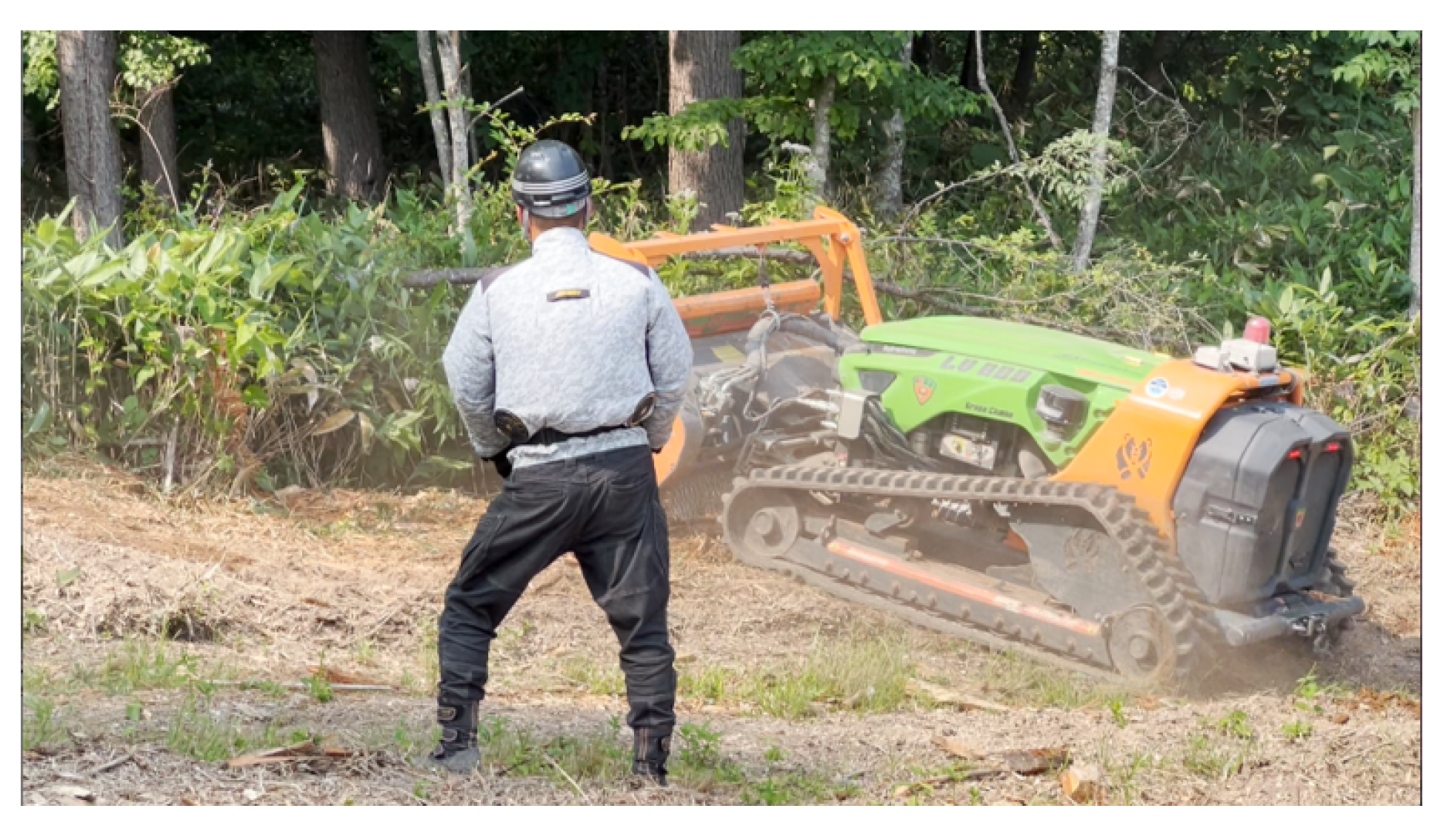
Furthermore, roCaGo is envisioned as more than just a transportation machine; it is also seen as a future autonomous vehicle and forestry work support system. For instance, it can serve as a “third-person-perspective support robot” to assist with the remote operation of existing ground preparation vehicles, such as the LV800 shown in
Figure 1 [
21]. The LV800 is a self-propelled crawler with a rotary mulcher that is useful for preparing the ground and clearing underbrush. However, securing visibility is necessary for remote operation [
22,
23]. Traditionally, operators observed the entire vehicle directly, but remote operation requires new means of providing a third-person perspective. Equipping roCaGo with cameras and LiDAR secures this perspective from a remote location, enabling operational support.
The following technological elements are crucial for remotely operating the LV800: Adaptation to narrow terrains via a compact, crawler-type mobility platform (less than 170 cm wide); high-precision self-positioning through RTK-GNSS and LiDAR-SLAM integration; network communication environments enabling non-line-of-sight remote operation and autonomous driving mode switching; and interchangeable work units, such as ground preparation blades, planting arms, and underbrush cutters, tailored to specific applications. These technologies are practical solutions based on actual worksite implementation and foundational technologies for the automation and advancement of forestry machinery.
The development of this machine is driven by four objectives: First, enhancing worker safety and reducing labor burdens in physically and radiologically demanding environments. Second, increasing the mechanization rate of forestry through affordable, operable robots to make reforestation in mountainous regions sustainable. Third, enabling consistent mechanical support from clearcutting to ground preparation, planting, and underbrush clearing to realize a cyclical forestry cycle. Fourth, accumulating operational data from demonstration sites, including Fukushima Prefecture, and envisaging the construction of a nationwide deployment scheme in conjunction with policies and systems.
This study presents foundational insights into the next generation of forest work and the resolution of transportation challenges through the mathematical modeling of roCaGo, control system design, and validation using prototype machines.
3. Design and Realization of roCaGo
In this section, the requirements for roCaGo are investigated. A prototype is designed and realized based on the investigation.
3.1. Requirement Definition of roCaGo
As mentioned in the research background, it is important to mechanize and improve the efficiency of post-clearcut afforestation work, which relies heavily on manual labor. In this study, we focus on the afforestation phase. The mechanization cycle we propose for the afforestation phase starts with a scenario in which the stand is weeded before clearcutting.
Weeding between the trees allows for better visibility of the ground and the root of the tree during the clearcut operation, and allows for a lower cutting position of the tree. As a result, the height of the stump after cutting can be reduced. When the stumps are low, the LV800 forestry machine shown in
Figure 2 can crush the root stumps and clear the land [
21]. In conventional forestry, root stumps could not be treated during the land-preparation phase, and seedlings were planted avoiding root stumps. Therefore, when the seedlings grew up and weeding was conducted in the summer, the buried root stumps impeded the movement of machinery. In other words, it was a serious factor that prevented mechanization of afforestation.
However, if the root stumps are crushed at the time of land preparation by LV800, and the seedlings are planted in a clean and well-prepared condition according to the scenario we have proposed, there will no longer be any obstacles between the seedlings. This means that the weeding work can be also automated using machines.
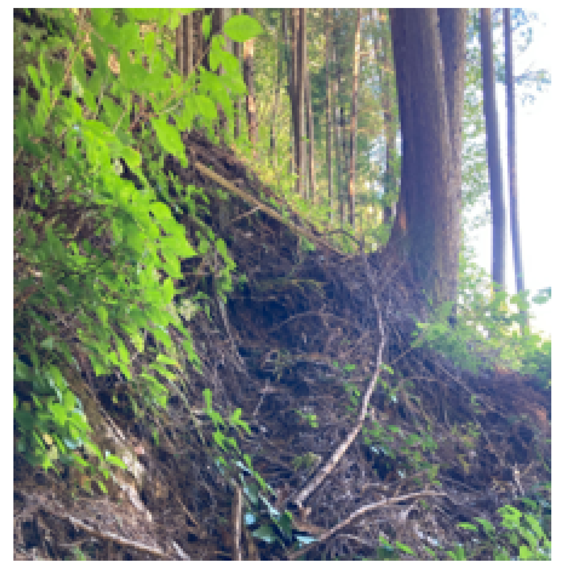
In order for the current forest to be included in this scenario, it is essential to perform weeding between standing trees, which is the starting point of the scenario. For this purpose, a control system that allows weeding machines to safely pass between the trees is necessary. In this study, a single-track vehicle called roCaGo is developed for preliminary design of routes between trees and for generating forest maps using LiDAR for weeding machines such as LV800. Hence roCaGo is required to be able to move even in narrow widths, such as between trees with slopes, as shown in
Figure 3; to carry simple loads; and to implement cameras and sensors to enable forest measurements. When moving through such areas, even people have to ascend and descend in switchback. The switchback is a method of climbing up steep slopes or mountain paths by zigzagging up the slope, thereby easing the steepness and making the ascent more efficient. By using this method, roCaGo can efficiently gain altitude even on steep terrain, and can proceed with the climb while taking the terrain into consideration. It is assumed that roCaGo is not fully autonomous, but rather that it moves while accompanying the user. Therefore roCaGo is designed to be able to switchback effectively so that it can move even on mountain roads, and also to allow forest measurement by the installed sensors.
As a result of the requirements, in this study, we propose a two-wheel-drive, two-wheel-steerable (2WD/2WS) motorcycle as a base to satisfy this requirement. The height of roCaGo should be about 1200 mm, since it is to be piloted by a person on a mountain road. The central beam should be equipped with a system for autonomous operation, sensors for forest measurement, and a hanging basket to carry supplies. According to these fundamental specifications, the next section describes the specific design and fabrication of roCaGo.
3.2. Design and Prototyping of roCaGo
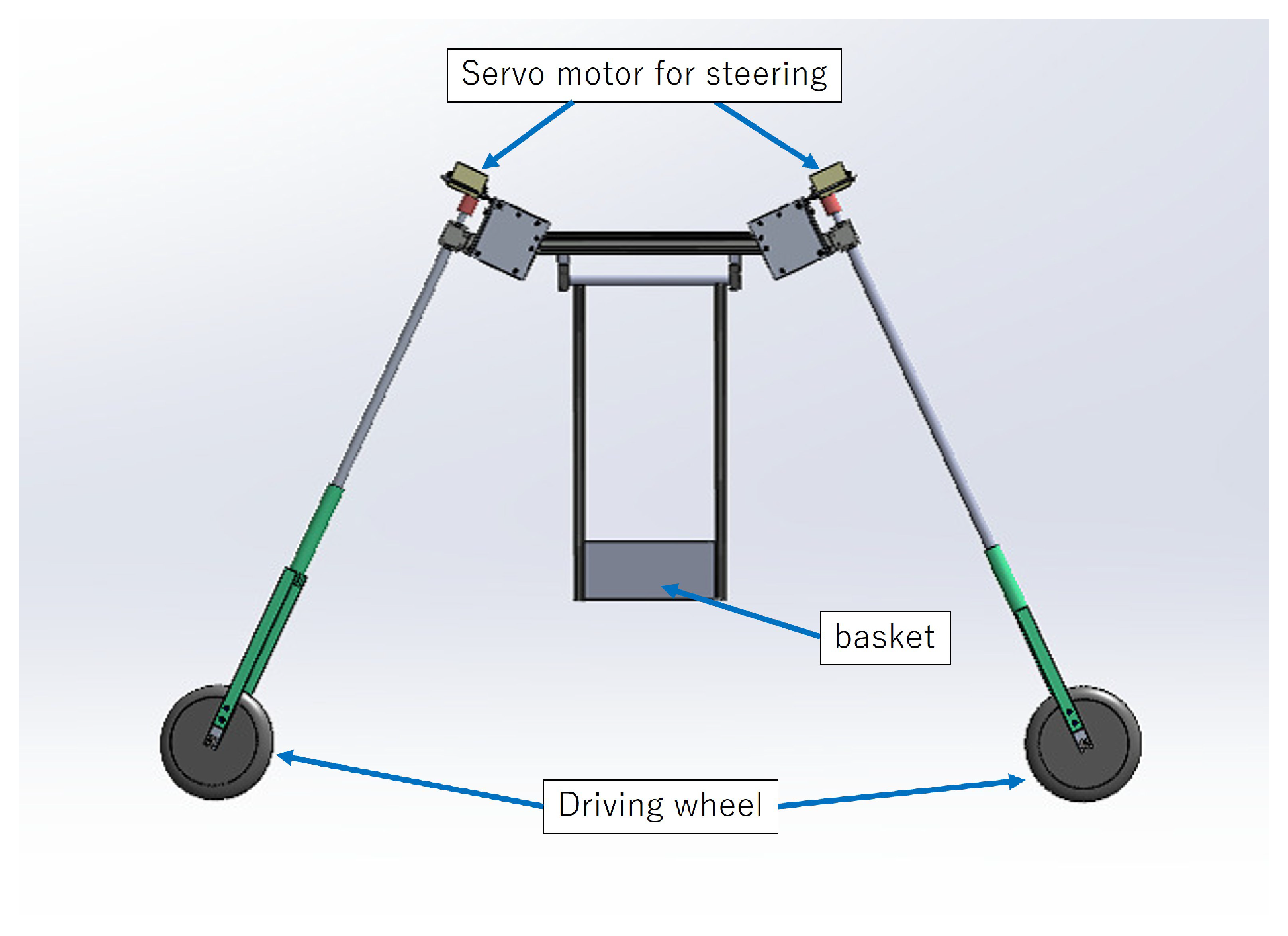
The design of roCaGo, with a 2WD/2WS structure based on the required specifications, is stated here. roCaGo consists of three elements: a front-/rear-wheel steering structure, a beam, and a cage for carrying supplies. First, the steering structure of the front and rear wheels is described. The steering structure of the front and rear wheels is presented in
Figure 4.
Figure 4 shows that an aluminum rod is used as the steering shaft, directly connecting the motor and the front or rear wheels. In this steering mechanism, couplings are used to connect the motor to the aluminum rod, and bearings to hold the rod and rotate it smoothly. The motors are servo motors, which are driven by commands from an Arduino.
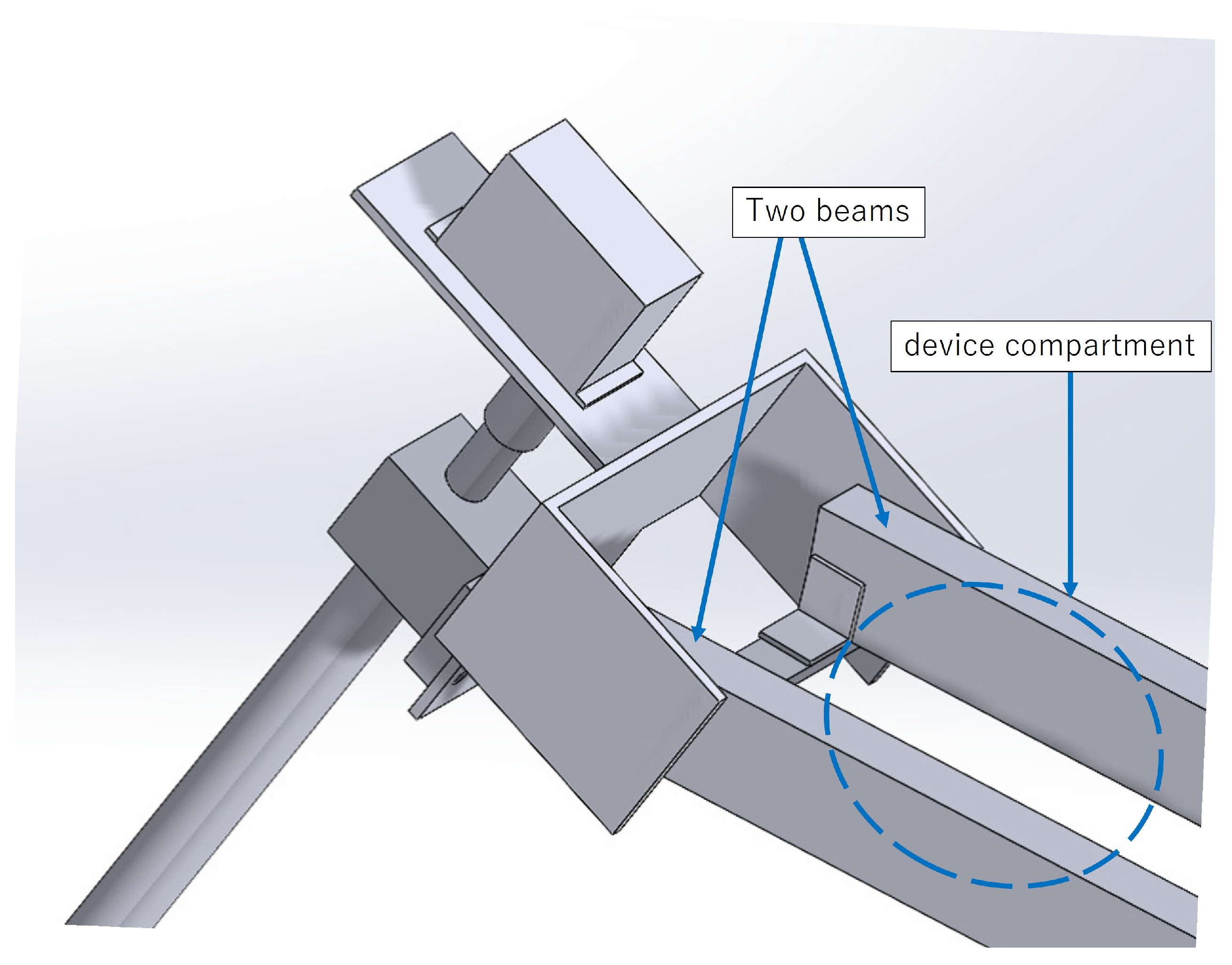
The beams connecting the steering mechanisms of the front and rear wheels are designed here. The 3D CAD in
Figure 5 shows the two beams are connected to the front and rear steering mechanism in parallel with jigs. This configuration creates a space between the beams, and allows for mounting of a battery, microcontroller, and other devices. This structure provides space in the fuselage for a microcontroller, battery, motor driver, and sensors.
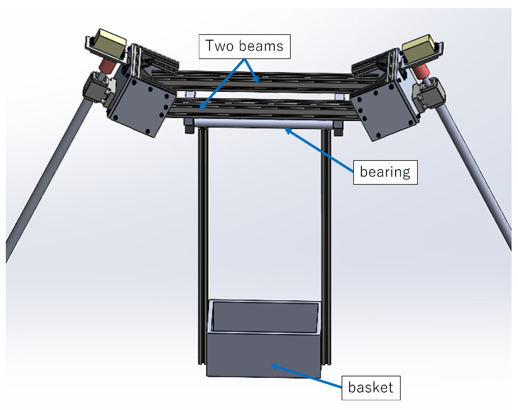
Finally, a basket for carrying luggage is shown in
Figure 6. The basket is suspended from the center of two beams.
The weight of one roll of deer-proof netting or a bundle of fallen branches, commonly used in forestry, is approximately 20 kg. Therefore, the basket mounted on roCaGo was designed to accommodate loads in the range up to 20 kg.
The aluminum rods hanging from the beams have a rotation axis with bearings and can swing freely in the roll direction. The prototype roCaGo is shown in
Figure 7 and
Figure 8.
4. System Configuration of roCaGo
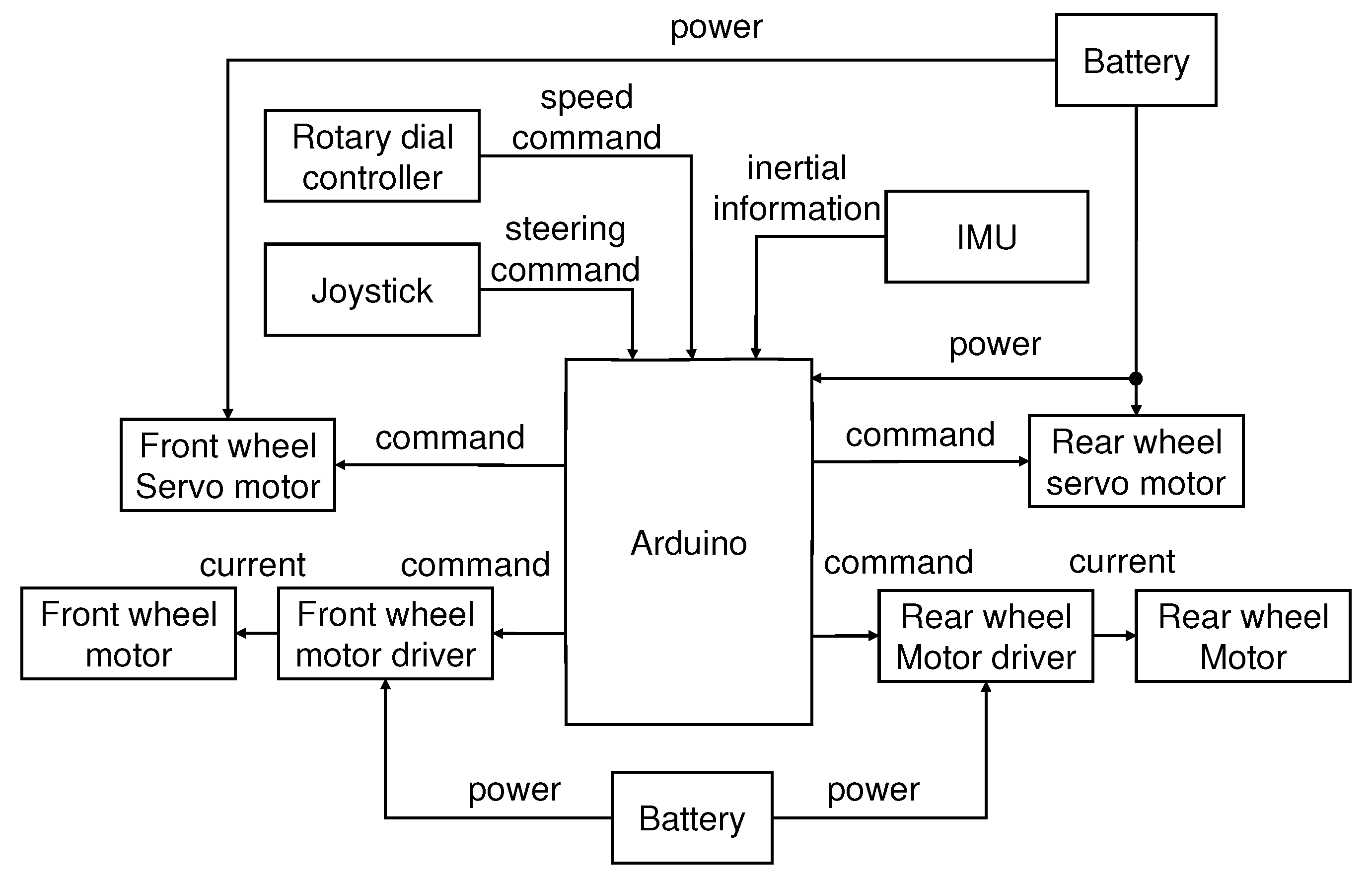
The system configuration of roCaGo is presented in
Figure 9. It consists of an Arduino as the main controller, front and rear drive wheels, a steering servo mechanism, and sensors.
The system is battery-powered. The battery powers the Arduino and motor drivers. Manual steering of the front and rear wheels can be performed by operating the analog stick. Feedback from the analog stick operation is sent to the Arduino and converted into the steering angle and direction (forward or backward) of the front and rear wheels. These converted steering angles are sent from the Arduino to the servo motors, which actuate the steering shafts of the front and rear wheels.
The rotary dial controller is used to adjust roCaGo’s traveling speed. The commands are sent to the motor driver to make roCaGo move in the direction determined by the analog stick at the traveling speed indicated by the dial controller. The IMU is used to estimate the attitude angle of roCaGo. As described below, the output from the IMU sensor is used to estimate the angular velocities around the roll, pitch, and yaw axes of roCaGo’s attitude.
The operation of the proposed system was verified, and the system performed as expected. The analog stick was moved forward/backward and left/right, and it was confirmed that forward/backward movement and left/right steering were performed according to the commands. When the rotary dial controller was turned, it was confirmed that the rotation speed of the front and rear wheels changed according to the dial rotation. It was also confirmed that the angular velocity output of the IMU sensor was acquired by the Arduino. The output was used to estimate the attitude of roCaGo.
The above shows that the roCaGo system was configured around the Arduino, and its operation was confirmed through experimental testing.
5. Attitude Estimation Using IMU
To achieve autonomous stabilization and semi-autonomous operation of roCaGo, it is necessary to stabilize its inherently unstable posture. For example, self-stabilization can be achieved by feeding-back the roll angle and roll angular velocity of the roCaGo body into the steering inputs. Since the IMU sensor is fixed to the roCaGo body, the output angular velocity vector is expressed in the body coordinate frame. Therefore, it is necessary to transform the angular velocity vector output from the IMU to correspond to the roll, pitch, and yaw axes, taking the rotation order into account. By integrating the transformed angular velocity components, the posture angles of roCaGo can be calculated. Below, we describe the calculation method for converting the angular velocity vector obtained from the IMU into roll, pitch, and yaw angular velocities.
Let
be the angular velocity vector measured by the IMU sensor. The amount of angular change,
, within the infinitesimal time
around the
axes, respectively, can be presented as
The small rotation angles obtained in (
1) are correlated with the attitude angles around the roll, pitch, and yaw axes. Let
, and
denote the rotation angles around the roll, pitch, and yaw axes, respectively. The small rotation angles around the roll, pitch, and yaw axes, i.e.,
, are related to
. The relation will be introduced here with the rotation matrices
, and
, that represent the rotation around the
, and
z axes, respectively.
The following relation should be satisfied between
and
:
where
I is an identity matrix of adequate size and
In (
6), the left- and right-hand sides have the same meaning, just from different perspectives. The difference in how the small rotation from the previous attitude is expressed is reflected in the difference between the left- and right-hand sides of the equation. The left-hand side expresses the small rotation as (
). That is, the roll, pitch, and yaw rotation angles representing the previous posture are
, and
, respectively. The equivalent roll, pitch, and yaw rotation angles that were slightly rotated during
are expressed as (
). The values of
, and
fall within the following ranges: the roll and pitch angles are within −90 to 90 degrees, and the yaw angle is within 0.0 to 360 degrees. The rotation adding (
) to the previous posture angle represents the current attitude transformation. On the other hand, the right-hand side represents the small rotation as (
). In the sensor coordinate system, connecting the latest small rotation transformation consists of the small rotation (
) around each axis
detected by the angular rate sensor during
to the rotational transformation with roll, pitch, and yaw attitude angles before
time has elapsed; this leads to the current attitude transformation.
From the relations in Equations (
5) and (
6), we obtain the approximation of sin and cos with respect to the small angles; the multiplication between small rotations can be neglected. Then, the small rotation angles (
) of the roll, pitch, and yaw axes are calculated by using the small rotation angles
obtained from the IMU sensors.
6. Modeling and Control Design
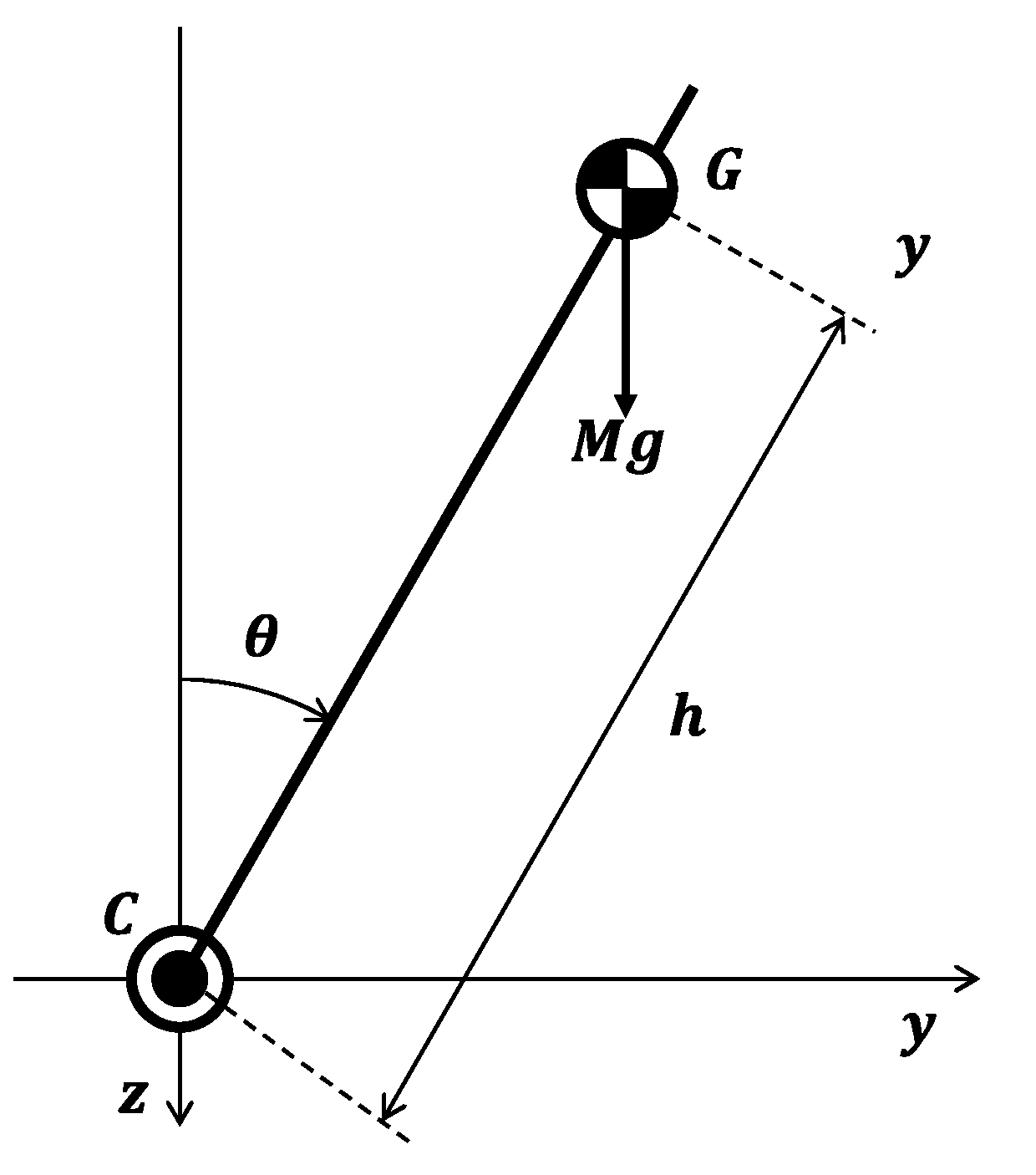
The dynamic model of roCaGo is derived based on its mechanism. The model of roCaGo, in which the front and rear wheels can be steered and driven, is shown in
Figure 10,
Figure 11 and
Figure 12.
Figure 10 shows the rear view,
Figure 11 shows the side view, and
Figure 12 shows the plan view.
Let M be the total mass of roCaGo, l be the wheelbase, be the moment of inertia around the x-axis in the right-hand coordinate system fixed at the center of gravity G, h be the distance between the ground point C where the z-axis intersects the ground and the center of gravity G, g be the gravitational acceleration, be the roll angle, and be the azimuth angle around the Z-axis. Let V be the running speed. roCaGo is designed to move at low speed. Therefore, it is assumed that the average speed is constant during a certain time interval.
The distances from the ground point C to the installation points of the front and rear wheels and are and , respectively; the steering angles of the front and rear wheels and are and , respectively; the camber angles of the front and rear wheels and , and the driving forces of the front and rear wheels are and , respectively.
Although the steering angle of roCaGo can rotate infinitely due to its structure, it is configured to operate within the range of −135 to 135 degrees to prevent entanglement of the wires connected to the drive motor.
For the front-wheel and rear-wheel parameters, the wheel radii are and , the head angles are and , the trails are and , and the offsets from the wheel centers are and .
Equation of Motion for Roll Angle
The equation of motion for the roll direction is expressed as follows;
where the first term on the right-hand side,
, is the torque due to centrifugal force; and the second term,
, is the restoring torque in the roll axis due to the yaw rate. The combination of the third and fourth terms represents the restoring torque in the roll axis from the head angle, front/rear driving force, and steering force.
The wheelbase equals the turning radius times the steering angle given by the difference in steering angle between the front and rear wheels. That is,
and the travel speed equals the turning radius times the yaw rate:
Then, the yaw rate is derived from (
9) and (
10) with the effect of the head angles
and
as follows:
Substituting (
11) into (
8) and rearranging it leads to the equation of motion for the roll angle:
where the approximation
is used with
.
7. Experimental Verification
Experiments using roCaGo were conducted to test its manual operation, semi-manual operation, and autonomous stable driving. First, the manual running experiment is described. As shown in
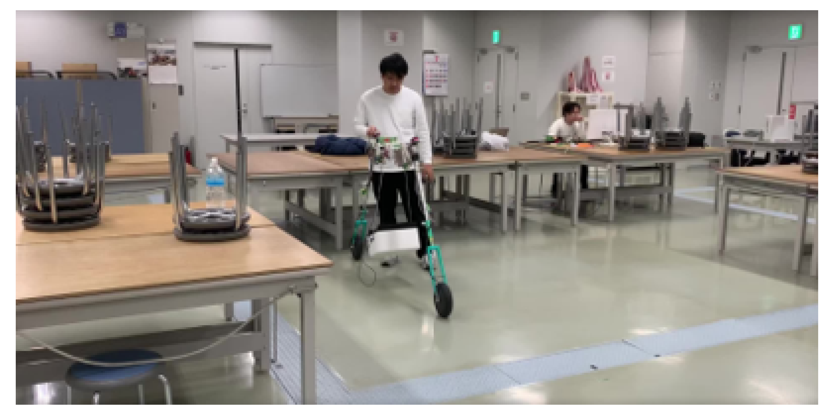
Figure 13, the operator stood next to roCaGo and operated the analog stick. By moving the analog stick forward/backward and left/right, the operator could check the forward/backward motion and left/right steering of roCaGo.
Figure 13 also demonstrates a palanquin hanging from the center of the main body for simple luggage transportation. It was tested that the rotational speed of the front and rear wheels could be changed using the rotary dial controller.
As a next step, a control system was designed to steer the front and rear wheels according to the roll angle of roCaGo. In this, the roll angle of the body is measured by the IMU and its information is transmitted to the Arduino. In this mode, the operator stands behind the roCaGo. When the operator tilts the roCaGo in the direction of the roll angle, the roCaGo should steer in that direction. Therefore, using the roll angle and roll angular velocity obtained from the IMU, the steering angles of the front and rear wheels are given by the following equation:
where
and
are the steering angles of the front and rear wheels. Although the steering angles of the front and rear wheels can be set individually, here they are determined to be the same. Equation (
13) is considered as a PD feedback using the roll angle
and the roll angular velocity
. Therefore
is a proportional gain and
is a derivative gain. In this experiment, each gain was adjusted to
and
.
By determining the steering angle using Equation (
13) and sending angle commands to the servo motor, steering is realized by the servo motor following the command. These control gains were obtained through simulations using a mathematical model, and the obtained control gains were applied to the autonomous driving experiment, leading to successful experimental results.
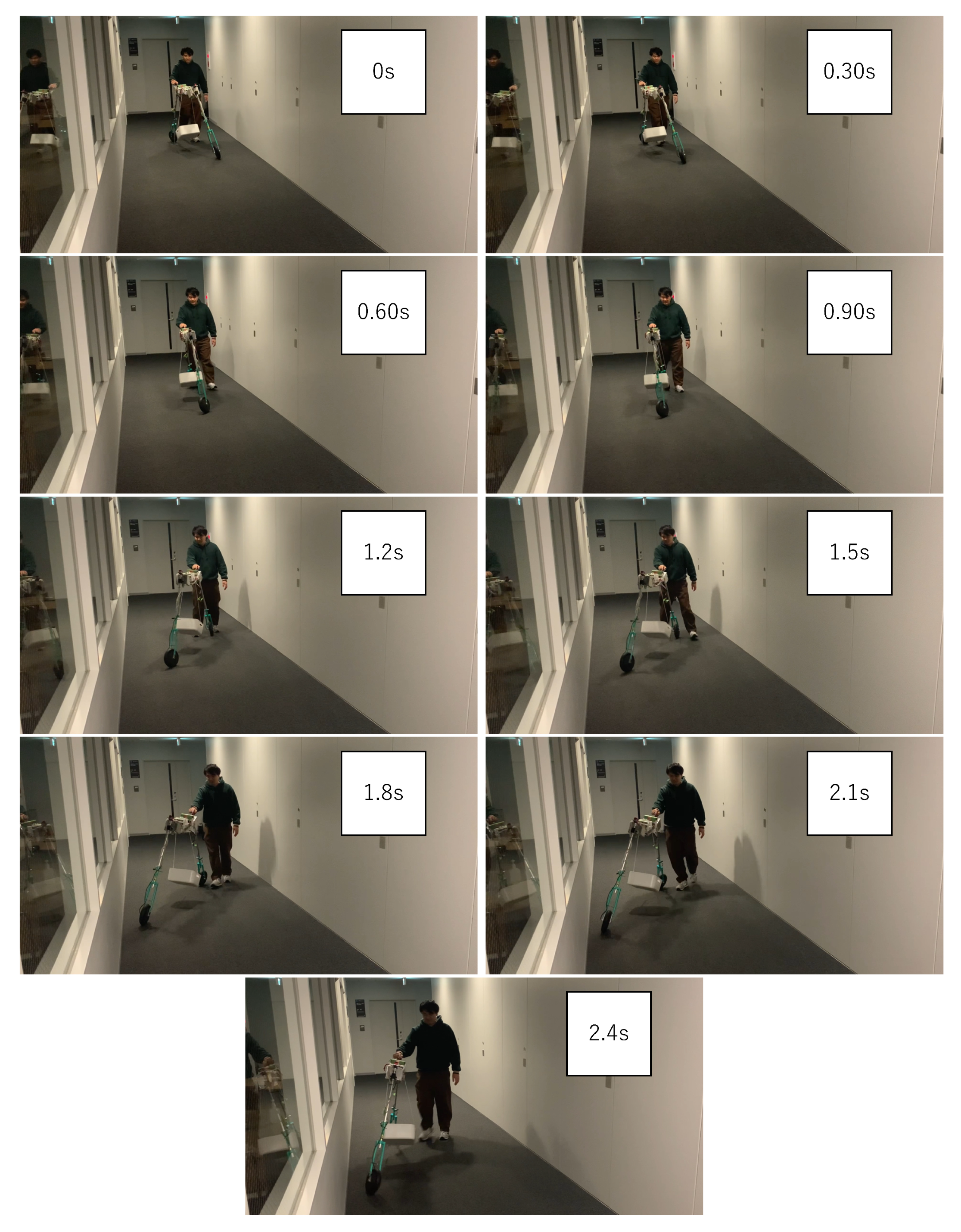
The experimental results are shown in
Figure 14. The figures show snapshots taken every 0.30 s. It is confirmed that roCaGo can be steered in the direction it is tilted.
Finally, autonomous driving with the feedback control presented in the previous section was verified by experiments. The proposed feedback control was compared with a case in which roCaGo was allowed to run without any manual steering while the semi-automatic steering angle PD control (
13) was applied. The driving speed was set to
m/s. The weight of roCaGo was
kg. The gains of the semi-automatic steering angle PD control used for comparison were set to
and
.
Figure 15 shows the experimental scene and
Figure 16 presents the experimental results. The semi-automatic PD control of the steering angle caused roCaGo to fall over after 7 s. On the other hand, the proposed feedback law caused roCaGo to wobble, but it maintained stability despite the wobble.
One of the reasons for the overturning observed in the semi-autonomous PD control of the steering angle was the delayed response in reaching the target steering angle. In future work, we plan to use higher-performance stepper motors and implement sliding-mode control to ensure robustness while realizing autonomous operation. Additionally, we will conduct verification tests of roCaGo in forest environments to evaluate its effectiveness in real-world conditions.
Since in basic use roCaGo is assumed to be accompanied by the user, fully autonomous stable driving is not necessarily required. However, if roCaGo is capable of autonomous stable traveling, it has the advantage of freeing up the user’s hands and allowing the user to perform other work. In addition, considering the use of roCaGo, it is preferable for roCaGo to be autonomously stable while stopped and to be able to stay in place. This is an issue to be addressed in the future.
8. LiDAR-Based Visualization Mounted on roCaGo
In order to place the current mountain forest in this scenario, it is essential to perform mowing between trees at the starting point, which requires a control system that allows the mowing machine to safely pass between standing trees.
To further promote automation in forestry, the autonomous operation of forestry machinery is essential. For a machine such as the LV800 (as shown in
Figure 1 and
Figure 2) to operate autonomously, it must maintain a detailed map of the forest environment, enabling accurate self-localization by matching onboard sensor information with the stored map. Even for remote operation under non-line-of-sight conditions, it is important to secure a third-person viewpoint to ensure that the front-mounted mulcher of the LV800 can properly access the designated work areas. Considering this, in addition to its basic role in cargo transport, roCaGo is equipped with the capability to acquire data necessary for forest mapping. A LiDAR sensor with a mapping accuracy of ±2.0 cm is installed on roCaGo to meet this requirement.
Figure 17 shows the configuration of the LiDAR measurement system. The measurement system is independent of the roCaGo control system and uses a Raspberry Pi 4B to collect and store synchronized point cloud data from the LiDAR sensor and acceleration and attitude data from the IMU. The collected data are processed offline on the external PC to generate the map shown in
Figure 18. Furthermore, the LiDAR data can be shared with the LV800 via a forestry area network. Our project collaborators are developing a method for constructing control barrier functions for obstacle avoidance by the LV800 based on point cloud maps obtained from the LiDAR. Thus, the generated maps can serve as essential environmental data for the remote operation of existing forestry machinery.
The roCaGo is not fully autonomous, but can move with the user. The vehicle is designed to be able to switchback effectively, so that it can move even on mountain roads.
9. Discussion
Conventional forestry machinery requires either the construction of wide, permanent forest roads or fixed rail systems, such as monorails. In contrast, roCaGo can transport materials along narrow, unprepared mountain paths, offering a unique advantage. This capability allows for efficient last-mile logistics without extensive infrastructure development, addressing a major barrier in current forestry operations.
Forests provide essential ecosystem services that contribute to human health and well-being and the sustainable development of society. However, steep, narrow forests, where vehicle access is restricted, present persistent challenges in maintaining mountain trails and forest roads and executing efficient reforestation operations. The so-called “last-mile problem” increases labor burden and reduces operational efficiency in such environments, highlighting the need for innovative solutions that can overcome topographical constraints.
This study focused on developing roCaGo to address this issue. roCaGo is a compact, two-wheeled robotic palanquin, equipped with driving and steering mechanisms, aimed at improving transport efficiency in forest logistics. Based on a 2WD/2WS mechanism, roCaGo can steer the front and rear wheels in the same or opposite directions, which enhances maneuverability, stability, and roll suppression on uneven terrain. Designed to operate alongside a walking operator, roCaGo ensures terrain adaptability and operational safety, even in rugged, mountainous areas where conventional machinery is ineffective.
Furthermore, roCaGo’s applicability was expanded to include serving as a mobile visual support platform for remotely operating existing forestry machinery. One example is the LV800 crawler vehicle, which is equipped with a front-mounted mulcher. Equipping roCaGo with LiDAR and cameras provides a third-person perspective, enabling non-line-of-sight teleoperation. Additionally, the LiDAR mounted on roCaGo was found to perceive forest environments and contribute to path planning during remote LV800 operation. These capabilities reduce labor demands and improve operator safety.
roCaGo’s mechanical structure and stabilization control system were developed based on a dynamic model, and their effectiveness was validated through numerical simulations and preliminary experiments. Field tests in actual forest environments demonstrated that roCaGo’s LiDAR-based sensing capability effectively supports the remote operation of the LV800.
These findings suggest that roCaGo is a promising next-generation solution for last-mile logistics in forestry, with the potential to improve labor efficiency and operational safety. Future research will focus on implementing more robust stabilization control methods, such as sliding-mode control, and conducting more practical, field-oriented experiments to enable fully remote operation with roCaGo.
10. Conclusions
This study proposed roCaGo, a compact two-wheeled robotic palanquin, as a solution for last-mile transportation in steep, narrow, forested areas. Its unique 2WD/2WS mechanism and operator-assisted design enhance stability and maneuverability on narrow mountain paths. Preliminary laboratory tests confirmed its stability and drivability, and field tests in forest settings demonstrated its feasibility as a mobile, third-person visual support platform for remotely operating existing forestry machinery, such as the LV800. These results highlight roCaGo’s potential to contribute to safer and more efficient forestry operations. Future work will focus on developing a robust control system, such as sliding-mode control, and achieving full-scale remote operation of forestry machinery using roCaGo, as well as conducting further field validation.
