Article

Multi-Physical Field Coupling Simulation and Experimental Study on the Radiation Characteristics of Sawing Noise from Circular Saw Blades in Woodworking

1
College of Mechanical and Electrical Engineering, Northeast Forestry University, Harbin 150040, China
2
College of Engineering, Northeast Agriculture University, Harbin 150030, China
*
Author to whom correspondence should be addressed.
Forests 2025, 16(3), 442; https://doi.org/10.3390/f16030442
Submission received: 23 January 2025 / Revised: 12 February 2025 / Accepted: 27 February 2025 / Published: 28 February 2025
(This article belongs to the Special Issue Wood Testing, Processing and Modification)

Abstract

:
High-precision noise radiation characterization is essential for designing circular saw blades aimed at vibration and noise reduction. However, previous studies have generally overlooked the effects of thermal stress, centrifugal force, and cutting force on the acoustic performance of saw blades during the cutting process. This paper proposes a multi-physics field coupling analysis method based on FEM/BEM joint simulation technology. By performing thermal-force coupling analysis to obtain the sawing vibration response, the resulting vibration acceleration is introduced into the acoustic–solid coupling model to predict the frequency-domain characteristics and spatial distribution of sawing noise. The validity of the simulation results is verified through sawing noise test experiments. The study shows that the circular saw blade radiates the most noise when sawing in the mid-frequency band from 500 Hz to 8000 Hz, while the noise radiation efficiency is lower in both the low-frequency band and the high-frequency band. The multi-physical field coupling simulation method can significantly improve the calculation accuracy of the frequency-domain characteristics of sawing noise. The vibration noise of the circular saw blade shows clear directional distribution at different excitation frequencies, while the directionality of the experimentally measured noise is less distinct. Furthermore, based on the noise radiation characteristics, this study explores the design strategies of noise reduction slots and sound barriers, which provide references for the noise control and vibration damping design of circular saw blades.

1. Introduction

With the promotion of green manufacturing and increasing awareness of worker health protection, the demand for noise reduction in the wood processing industry is growing. Circular saw blades, the primary cutting tools in wood production, generate significant vibrational noise at high rotational speeds and feed rates, with noise levels reaching 110 dB [1]. This not only jeopardizes workers’ health but also reduces processing quality, shortens the lifespan of saw blades, and increases maintenance costs [2]. Therefore, conducting comprehensive research on vibration control and noise suppression technologies has become essential in the circular saw blade manufacturing industry.
Current research on vibration and noise reduction in circular saw blades primarily focuses on controlling noise sources and blocking propagation paths. Noise source control methods commonly include optimizing sawing parameters [3] (e.g., rotational speed, feed rate, sawing depth), improving saw blade design [4,5,6] (e.g., adding damping materials, slotting designs), and employing active control techniques [7] (e.g., adaptive control systems) to reduce noise intensity. Blocking noise propagation is typically achieved by enhancing worker protection and modifying the acoustic impedance of propagation media (e.g., sound barriers, non-contact guidance systems) to mitigate the noise’s impact on human health [8,9]. Despite the effectiveness of the aforementioned strategies in mitigating circular saw blade noise, significant limitations remain in practical applications. Achieving the desired outcomes is often difficult, especially when the noise radiation characteristics are unclear. Therefore, an in-depth study of the radiation characteristics of sawing noise, especially the frequency-domain response and spatial distribution, is crucial for the effective selection of vibration and noise reduction techniques and the optimization of circular saw blade design.
Early studies primarily focused on classifying the sources and propagation paths of saw blade noise, with less attention given to the noise propagation characteristics and the spatial distribution of the sound field [10,11,12]. This limitation stemmed from the fact that, at the time, circular saw blade noise could only be analyzed qualitatively using mathematical methods, with no means for quantitative calculations. As a result, the exploration of noise generation mechanisms and control measures was severely constrained. Recently, several methods for the quantitative analysis of noise have been developed, offering more effective tools for studying noise propagation mechanisms and optimizing control strategies.
In the study of structural vibration and noise radiation, the finite element method (FEM) and boundary element method (BEM) are widely used. FEM is effective for complex vibration analysis by discretizing structures into finite cells and applying the variational principle to solve dynamic equations. BEM handles the propagation, reflection, and scattering of acoustic waves in open space through the boundary integral method. This approach is particularly effective in addressing the far-field radiation and transmission of acoustic waves and offers significant advantages in reducing computational effort. Studies [13,14,15] applied the FEM/BEM co-simulation method to analyze vibration noise propagation and radiation in automobiles, underwater thin-shell structures, and electric motors. For the vibration noise analysis of circular saw blades, studies [16,17,18] also employed FEM to calculate the modal and vibrational response, and used BEM to predict noise under various frequency-domain excitations.
However, most existing studies simplify the modal and vibration response analysis of circular saw blades, neglecting the effects of cutting force and heat on the modal characteristics during the sawing process. This results in inaccurate acoustic field boundary conditions and compromises the accuracy of the simulation outcomes. In recent years, the multi-physical field coupling method has emerged as a powerful numerical simulation technique, significantly improving the accuracy of complex system simulations and providing a more reliable analysis method for the subsequent optimization of design [19,20,21]. In the aerodynamic noise analysis of circular saw blades, study [22] successfully predicted noise under idle conditions using a flow field–structure–acoustic field model. Nevertheless, it did not account for the noise characteristics under actual sawing conditions.
In this study, a joint FEM/BEM simulation method is adopted to establish a simulation model of sawing noise under the action of multi-physical field coupling. Combining simulation and experiment, the noise radiation characteristics of circular saw blades are discussed in depth. Firstly, the forced vibration response of the circular saw blade is obtained by calculating the dynamics of the sawing system under thermo-mechanical coupling. Then, the vibration response data are incorporated into the acoustic–structural coupling model to derive the acoustic radiation characteristics of the circular saw blade. Subsequently, the simulation results are compared with the experimental data to validate the accuracy of the noise prediction. The integrated numerical simulations and experimental data systematically analyze the frequency-domain response characteristics and directional distribution law of sawing noise, clarify the spatial directivity of the noise, and discuss the design methods of the noise reduction slot and sound barrier.

2. Multi-Physical Field Coupling Model for Sawing System

During the sawing process, the intrinsic properties of circular saw blades continuously change, complicating the calculation of surface vibration and its conversion into noise radiation. To clearly elucidate the multi-physical field coupling mechanism, the calculation of sawing noise is divided into two sub-models: thermo-mechanical coupling and acoustic–structural coupling. Using the thermo-mechanical coupling model, the stress distribution of the circular saw blade under dynamic load and temperature is first calculated via the finite element method (FEM), followed by the vibration response obtained through pre-stress modal and harmonic response analysis. In the coupled acoustic–structural model, the vibration response data calculated by FEM are used to compute the radiated sound pressure level of the circular saw blade with the boundary element method (BEM).

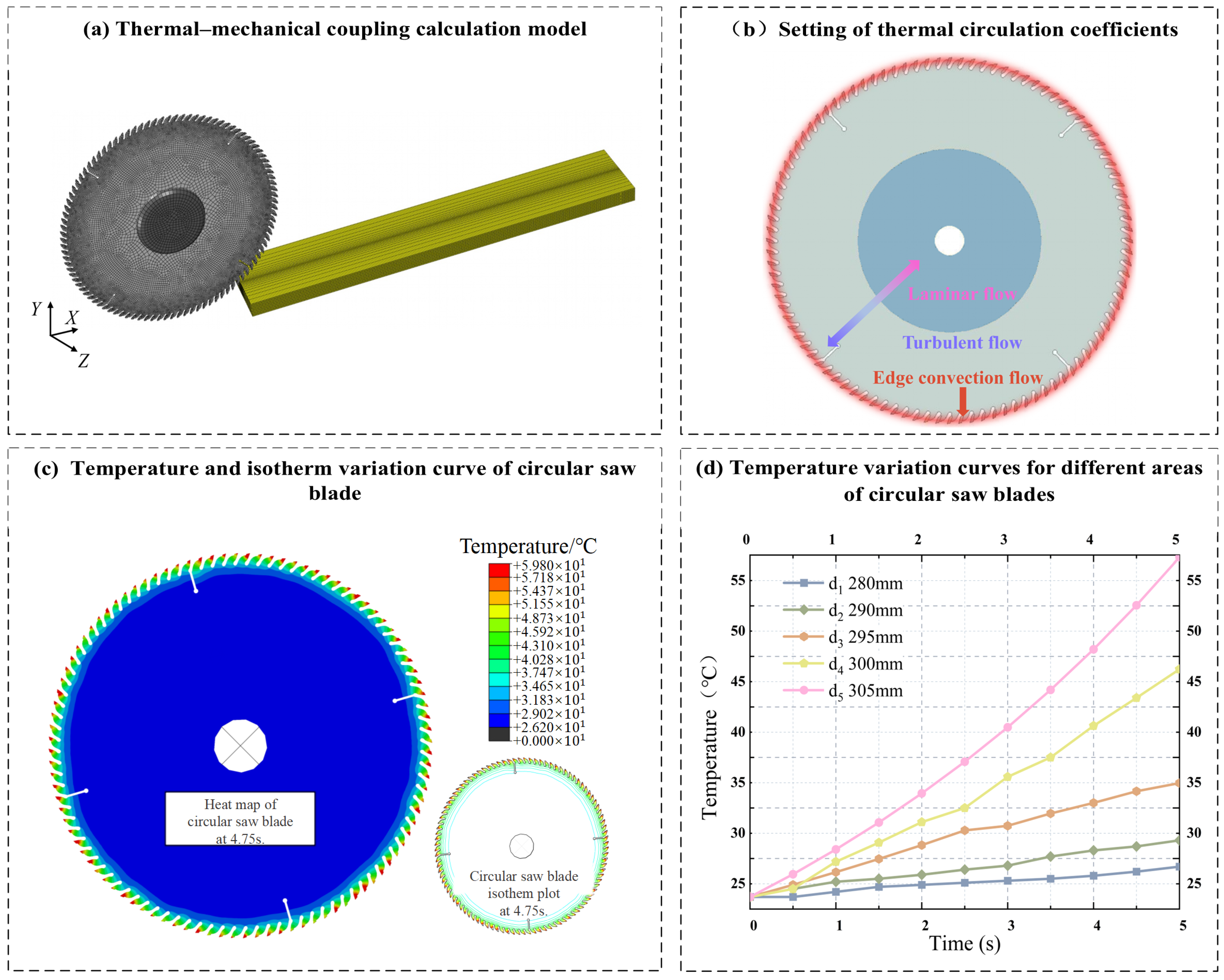
2.1. Thermo-Mechanical Coupling Model

(1) Heat transfer calculation
The thermo-mechanical coupling (TMC) effect in the sawing system refers to the changes in stress distribution and inherent properties of circular saw blades caused by the simultaneous action of temperature variations and mechanical loads (e.g., cutting forces) during the cutting process [23]. Equations (1) and (2) describe the coupling of the thermal and force fields.
T t = α 2 T + Q ρ c
where T is the temperature field; α is the thermal diffusion coefficient; ρ is the density; c is the specific heat capacity; and Q is the heat source term.
σ = E ε ε T
where σ is the stress; E is the modulus of elasticity of the material; ε is the total strain; and ε T is the thermal strain, the magnitude of which is influenced by the coefficient of thermal expansion of the saw blade material and the amount of temperature change during sawing.
In thermo-mechanical coupling analysis, there is an interaction between the temperature field and the stress field. This interaction requires an iterative solution process to achieve mutual feedback between the heat source term Q and the thermal strain ε T . The governing equations are given in Equation (3).
K T K C K C K σ Δ U T Δ U σ = F T F σ
where K T is the stiffness matrix related to heat transfer; K C is the heat–force coupling matrix reflecting the interaction between temperature field and stress field; K σ is the mechanical stiffness matrix; Δ U T and Δ U σ are the displacement increments of temperature and stress, respectively; F T and F σ are the internal forces generated by thermal stresses and external loads, respectively. Each iterative time step involves solving a set of coupled equations, typically using explicit or implicit time integration methods to determine the structural response. The iterative process updates the interaction between the temperature field and the stress field, simulating the dynamic stress distribution of the circular saw blade.
(2) Pre-stress modal calculation
Literature [24] indicates that the intrinsic frequency and mode shapes of the circular saw blade during sawing are primarily influenced by thermal and centrifugal stresses. The total stress can be approximated as the sum of these two, with cutting stresses having a minimal effect. Therefore, the key to pre-stress modal analysis is to adjust the stiffness matrix of the saw blade by incorporating thermal and centrifugal stresses, followed by solving for the corrected modal shapes. Since the main form of vibration of circular saw blade is transverse vibration, its transverse modal calculation is carried out [25]. The pre-stress-induced modal characteristics are formulated as eigenvalue problems, with the modified eigenvalue equation given in Equation (4).
[ K + K g λ M ] Φ = 0
where K is the stiffness matrix of the circular saw blade; Kg is the geometric stiffness matrix due to pre-stress; λ is the eigenvalue corresponding to the square of the intrinsic frequency of the saw blade, i.e., λ = ω 2 and ω is the intrinsic frequency; M is the mass matrix of the circular saw blade; and Φ is the eigenvector, which denotes the vibration patterns of different modes of the circular saw blade, and is usually obtained by solving the generalized eigenvalues by numerical methods (QR damping method, Lanczos method, etc.).
(3) Vibration response calculation
The primary vibration mode of the saw blade is transverse vibration. During the wood sawing process, the circular saw blade does not exhibit significant nonlinear behavior (e.g., large deformations or buckling). Based on Kirchhoff’s thin plate theory, its dynamic behavior can be approximated as a linear system. This study employs the modal superposition method to calculate the vibration response of the circular saw blade, as expressed in Equation (5).
u ¨ ( ω e ) = i = 1 n u i u i T F ( ω e ) ω i 2 ω e 2 + 2 j ζ i ω i ω e
where u ¨ ( ω e ) denotes the acceleration response of the structure at the excitation frequency ω e ; u i is the vibration pattern of the ith order mode of the structure; F ( ω e ) is the applied excitation force; ζ i is the damping ratio of the ith order mode; ω i is the intrinsic frequency of the ith order modes and ω e is the excitation frequency. The vibration acceleration response results will be used as the boundary conditions of the acoustic–structural coupling model for calculating the acoustic radiation characteristics of the saw blade. The vibration acceleration response will serve as the boundary condition for the acoustic–structural coupling model, which calculates the acoustic radiation characteristics of the circular saw blade.

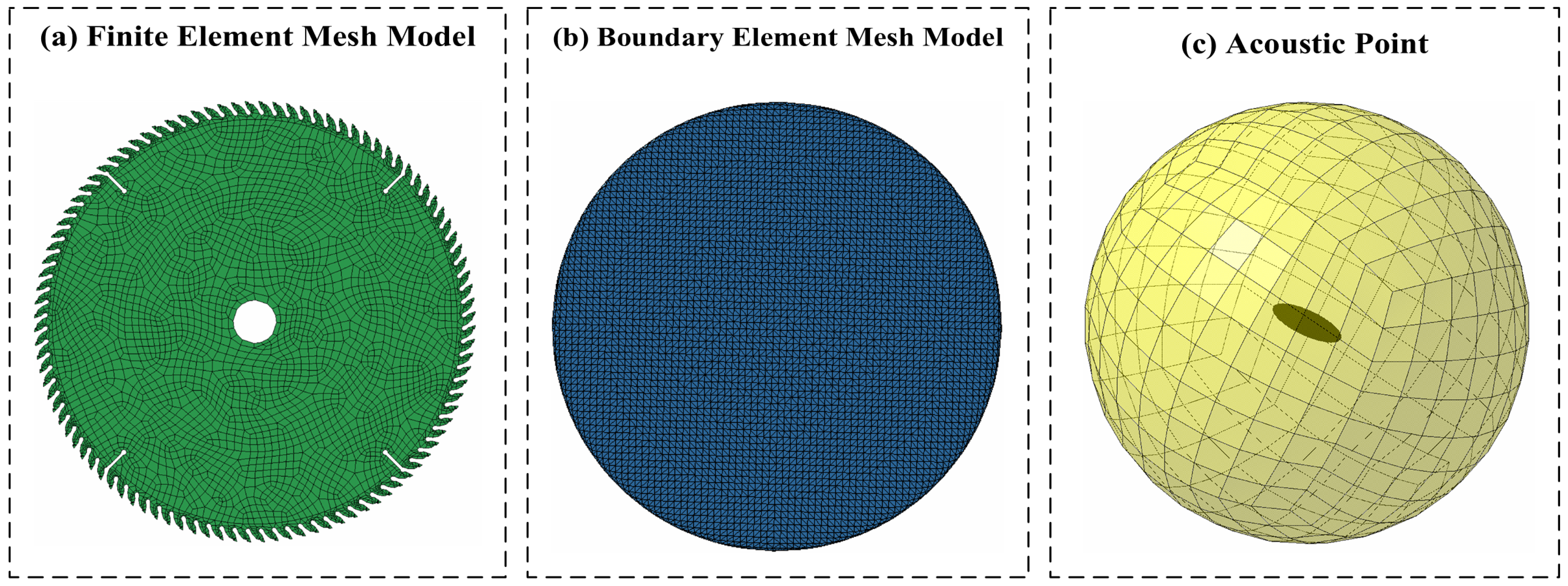
2.2. Acoustic–Structural Coupling Model

The vibration of a circular saw blade generates acoustic radiation through its interaction with the surrounding air, which can be described as an acoustic–structural coupling phenomenon. The key issue is to describe how the vibration of the saw blade surface induces acoustic pressure fluctuations in the surrounding medium, leading to a complex acoustic field distribution. In this study, the acoustic medium is assumed to be an ideal fluid, and the vibration response of the circular saw blade is assumed to adhere to the linear small amplitude condition. Consequently, the propagation of acoustic pressure follows the Helmholtz equation [26], with the relationship between the surface normal velocity of the circular saw blade and the acoustic pressure on the acoustic boundary surface given by Equation (6).
p n = ρ 0 ω e 2 u n
where p n represents the sound pressure gradient in the direction normal to the surface of the structure; ρ 0 is the medium’s density; and u n is the displacement normal to the surface. The basic equation for calculating the magnitude of sound pressure at any point in space using the boundary element method is given by Equation (7) [27].
p ( r ) = Γ G r , r p r n p r G r , r n d Γ
where p ( r ) is the sound pressure at the observation point r ; G ( r , r ) denotes the propagation of the sound wave from the boundary point r to the observation point r . To reveal the frequency-domain distribution of the saw blade’s sound field, the Fourier transform is applied to convert the time-domain sound pressure signal into a frequency-domain signal, as shown in Equation (8).
p ( ω e ) = + p ( t ) e j ω e t d t
where p ( ω e ) is the sound pressure frequency-domain signal; p ( t ) is the sound pressure time-domain signal; ω e is the frequency; and j is the imaginary unit. The magnitude of the sound pressure in the frequency domain is usually expressed in terms of the amplitude of the sound pressure in that frequency domain, and the amplitude | p ( ω e ) | can be expressed as the modulus of the real and imaginary parts of the complex number, which is computed by Equation (9).
| p ( ω e ) | = ( p ( ω e ) ) 2 + ( p ( ω e ) ) 2
where ( p ( ω e ) ) denotes the real part of the complex p ( ω e ) and ( p ( ω e ) ) denotes the imaginary part of the complex p ( ω e ) . Further, the energy distribution of each frequency component is quantified by calculating the Power Spectral Density (PSD), which is calculated by Equation (10).
S p ( ω e ) = lim t + 1 t t / 2 t / 2 p ( t ) e j ω e t d t 2
where S p ( ω e ) denotes the power spectral density at frequency ω e and T is the signal duration; for discrete time-domain signals, the discrete Fourier transform (DFT) or fast Fourier transform (FFT) can be used to calculate the frequency-domain sound pressure by Equation (11).
P ω k = n = 0 N 1 p n e j 2 Π k n N
where P ( ω k ) is the sound pressure at the kth frequency point, p n is the nth sample of the time-domain signal, N is the total number of samples, and ω k = 2 Π k n N is the discrete frequency. With the above calculation method, the sound pressure amplitude and energy distribution of the saw blade at different frequencies can be quantified.

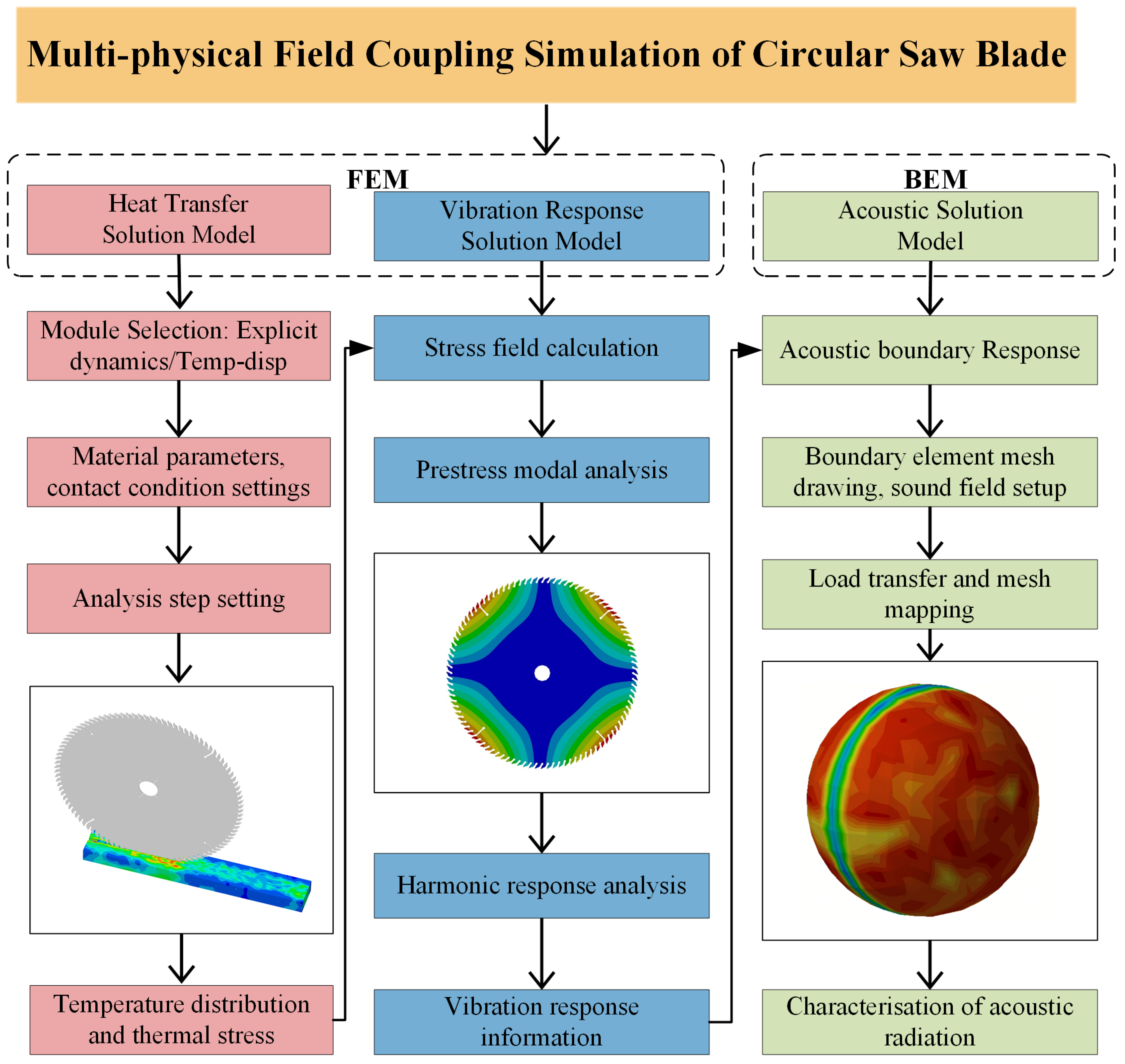
3. Multi-Physical Field Coupling Model Solving

The circular saw blade, plate, and air domain are integrated into a unified system using ABAQUS CAE 2024, ANSYS 2021 R1, and LMS Virtual.Lab 13.10 simulation platforms. This system is employed to examine the intricate interactions of thermal, mechanical, acoustic, and various multi-physical field coupling domains. The model-solving process is illustrated in Figure 1.

3.1. Materials

The accuracy of the multi-physical field coupling depends on the precise definition of material properties. In this study, SKS51 is selected as the saw body material for the circular saw blade, and YG6 is chosen for the serrated material. The material properties are provided in Table 1.
The object being cut is particleboard, which has stable performance and is widely used in furniture manufacturing and building decoration. Its main physical and thermodynamic properties are shown in Table 2 [28].

3.2. Multi-Physical Field Coupling Simulation Process

3.2.1. Thermal Conduction Simulation

This study employs the Temp-Disp module in Abaqus CAE 2024 to perform thermal conduction simulations for the sawing system. The analysis step setup is illustrated in Figure 2a. The geometric parameters are as follows: an inner hole diameter of 30 mm, an outer diameter of 305 mm, a saw body thickness of 1.5 mm, a serrated thickness of 2 mm, 100 teeth, a clamp diameter of 120 mm, and four thermal expansion slots. In the numerical simulation, the circular saw blade is modeled as a rigid body. The boundary conditions are a circular saw blade speed of 3000 rpm, a feed rate of 4 m/min, and a cutting depth of 2 mm. The contact conditions are as follows: the dynamic friction coefficient between the serrated and the particleboard substrate is 0.35, and the static friction coefficient is 0.4 [29].
To accurately describe the heat exchange process on the surface of the saw blade, the method from reference [30] is employed to calculate the convective heat transfer coefficient. The area within a 152.25 mm radius from the saw blade is designated as the laminar flow zone, with a convective heat transfer coefficient of 40.47 W/(m·K). The area beyond this radius is considered the turbulent flow zone, with a convective heat transfer coefficient of 79.60 W/(m·K). At the edge of the saw blade, the convective heat transfer coefficient is 2120.46 W/(m·K), as shown in Figure 2b. Additionally, it is assumed that approximately 60% of the frictional energy generated between the circular saw blade and the chips during the sawing process is converted into thermal energy. Therefore, this part of the thermal energy conversion rate is set to 0.6 [31].
To observe the temperature variation of the circular saw blade during the sawing process, the cutting duration was set to 5 s. Figure 2c illustrates the temperature distribution at t = 4.75 s. The temperature variation curve of the circular saw blade is presented in Figure 2d. After cutting begins, the temperature of the serrated rises rapidly, transferring heat to the saw body. The isotherms become progressively sparser, indicating a decreasing temperature difference, with the substrate temperature stabilizing at ambient levels.

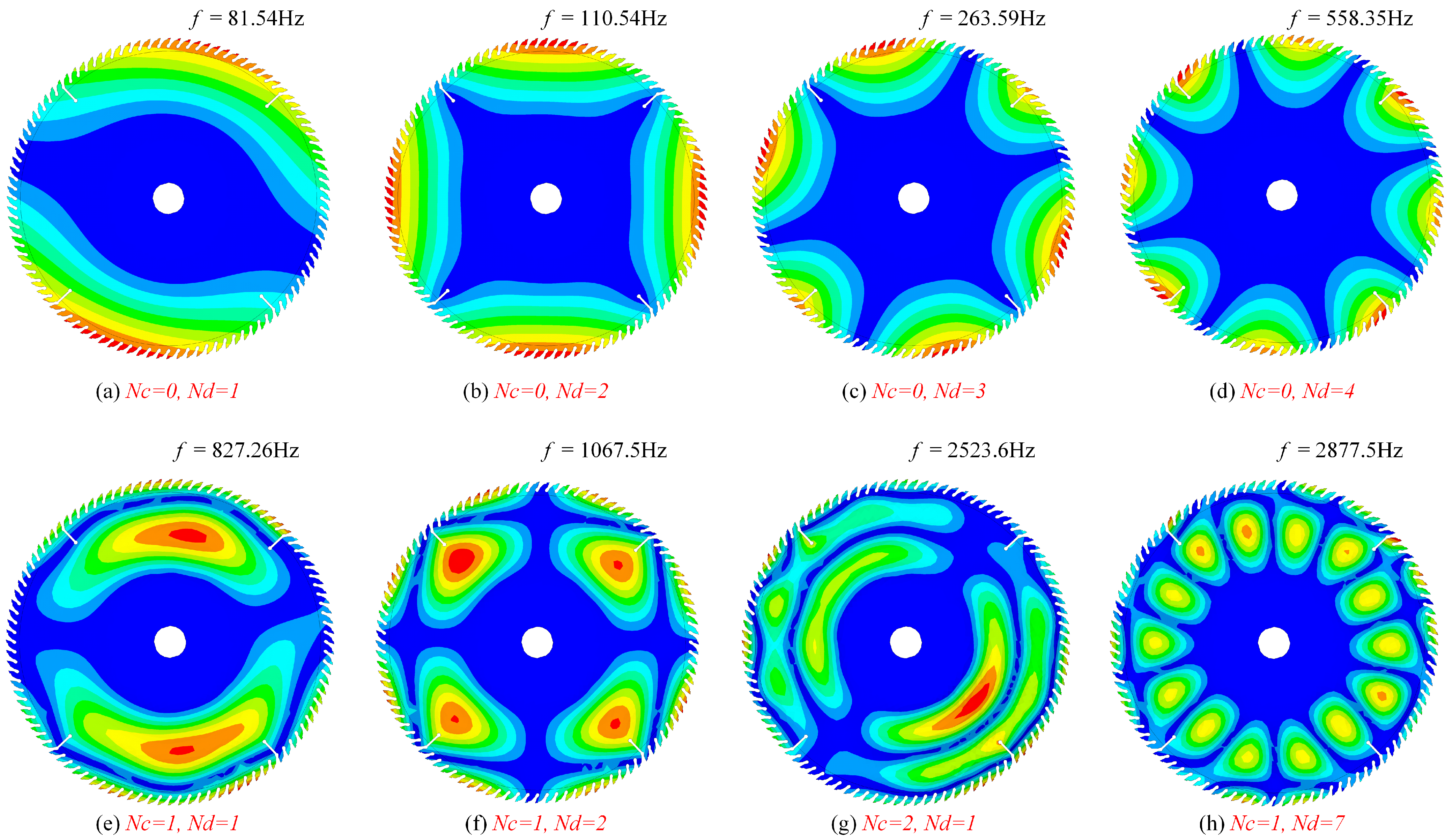
3.2.2. Pre-Stress Modal Simulation

This study performs pre-stressed modal analysis of the circular saw blade using ANSYS APDL 2021 R1 to simulate its modal characteristics under the combined effects of thermal and centrifugal stresses. The Shell 181 element, suitable for simulating pre-stress effects, is chosen to model the saw blade, with a mesh size of 2 mm. We apply full constraints to all nodes of the circular saw blade’s inner hole, and apply all constraints except for the axial rotation direction to the nodes within the flange range. The simulation results, shown in Figure 3, illustrate several modal vibration patterns of the saw blade under thermal and centrifugal stresses.

3.2.3. Vibration Response Simulation

During plate cutting, the transverse vibration of the saw blade is primarily influenced by excitation loads, which exhibit broadband and random characteristics. The excitation load’s frequency components include the fundamental frequency related to the saw blade rotation, the primary excitation frequency from the interaction between the teeth and material, and their higher-order harmonic frequencies. Additionally, the anisotropy of the particle board during cutting introduces random frequency components [32]. Therefore, evaluating the frequency-domain vibration characteristics of circular saw blades requires the use of a broadband excitation load, rather than relying solely on a single frequency or narrow-band excitation.
This study defines the excitation load frequency-domain parameters within the range of 20 to 20 kHz, with a load amplitude of 1 N and a frequency step of 20 Hz. This setup ensures coverage of low-, intermediate-, and high-order modal responses of the saw blade, effectively spanning the frequency range required for 1/3 octave analysis.

3.2.4. Sound Field Radiation Simulation

Building on the vibration response analysis of the circular saw blade, additional simulations were performed to investigate its acoustic radiation characteristics. The “cdwrite” command in ANSYS 2021 R1 was used to export the saw blade model and extract the surface vibration response data, which were then used as boundary conditions in LMS Virtual.Lab 13.10 for acoustic analysis. The direct boundary element method was applied to compute the sound pressure levels. The relationship between the radiated noise and surface vibration velocity of the circular saw blade is expressed by Equation (12).
L w = 10 log ρ 0 cS + 10 log σ + 20 log < u 2 > 120
where L w is the acoustic power, ρ 0 is the medium density, c is the speed of sound, S is the surface area radiated by the circular saw blade vibration, σ is the radiation efficiency, and < u 2 > is the spatio-temporal mean square value of the saw blade surface vibration.
The fluid medium is air, with a density of 1.225 kg/m3, a sound speed of 340 m/s, and a reference sound power level of 1.0 × 10⁻¹² W. The frequency range for the acoustic field solution is from 20 Hz to 20 kHz, covering the full analysis band from low to high frequencies. A convex hull mesh was used to construct the acoustic unit, preventing sound leakage due to the circular saw blade’s central hole [33].
The study employed a spherical field layout for the arrangement of acoustic field points, simulating the spatial distribution of the sound field radiated by the saw blade. Based on this, a quantitative assessment of the sound field characteristics at different frequencies was performed using 1/3 octave analysis. The arrangement of the relevant field points is presented in Figure 4.

4. Design of Experiments
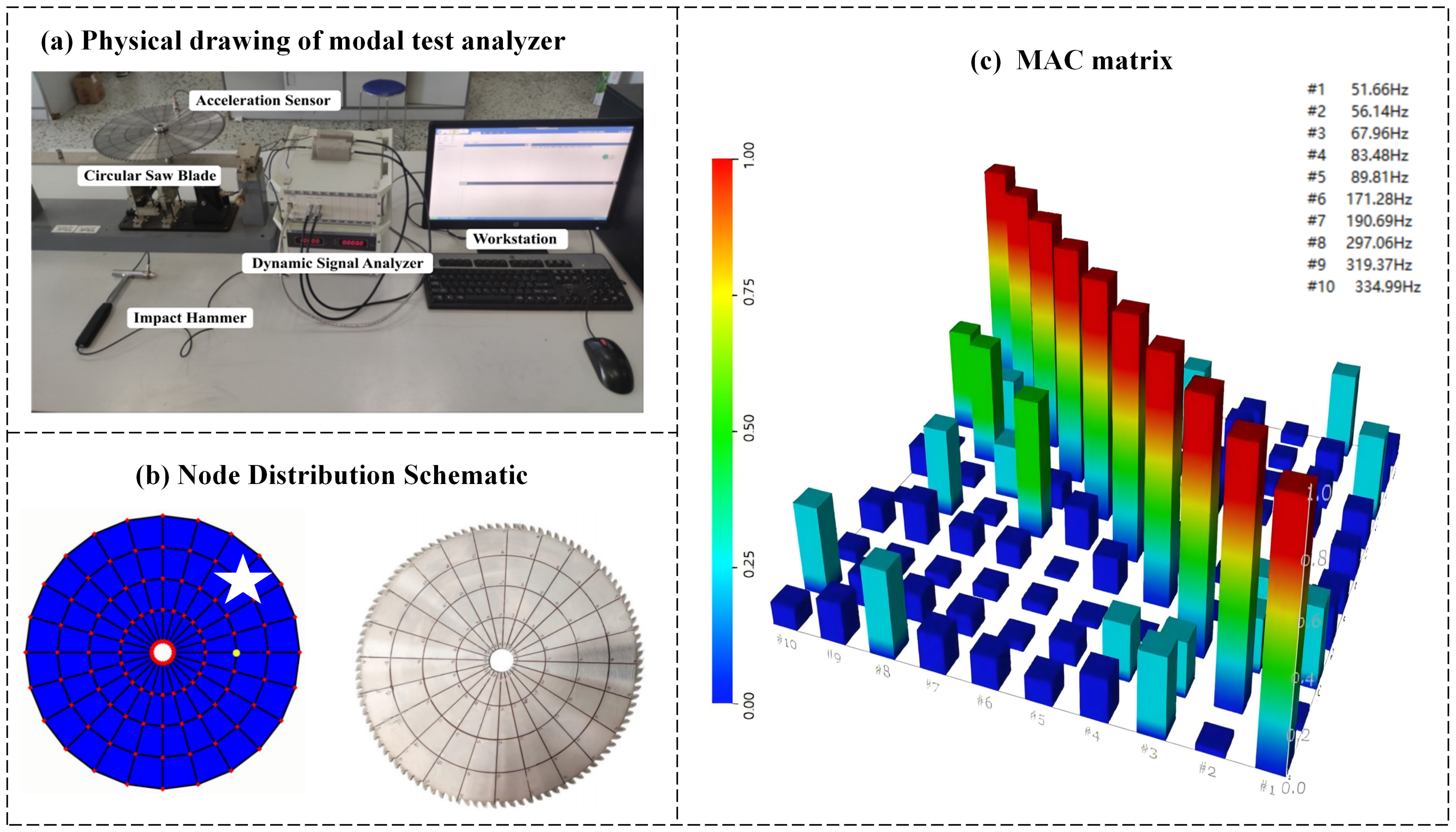
4.1. Modal Test

To validate the accuracy of the modal and vibration simulation results, the modal characteristics of the saw blade were experimentally verified in this study. The experiment employed the hammering method, with the center hole of the saw blade restrained by a fixture (radius: 15 mm) to create a hybrid restraint condition. The experimental setup consisted of DHDAS signal test and analysis software, a DH5922 dynamic signal analyzer, a DH5855 charge amplifier, a DH103 piezoelectric acceleration transducer, a force hammer, and a workstation (Donghua Testing Technology Co., Ltd. Taizhou, China), all used for data collection and processing, as shown in Figure 5a.
Measurement points were arranged as shown in Figure 5b, with a test frequency range of 0 to 1000 Hz and an analysis frequency range of 0 to 400 Hz. Sensors were placed at the node positions marked by the white pentagram symbols in the figure, with data acquisition repeated five times for each impact. The reliability of the hammering test was assessed using the Modal Assurance Criterion (MAC) matrix [34], as shown in Figure 5c.

4.2. Noise Test

To verify the accuracy of the acoustic radiation simulation and further investigate the radiation characteristics of sawing noise, noise tests were conducted under both no-load and sawing conditions. A precision cutting saw MJ-90 (Baoshan Woodworking Equipment Factory. Shenyang, China) was used, with test conditions matching those of the numerical simulations. Data from the stable sawing phase were collected and analyzed. The noise measurements were conducted using the AWA-6292 sound level meter (Aihua Instrument Co., Ltd., Hangzhou, China). This device features an overall value integration function and 1/3 octave analysis capability. The measurement range spans from 20 dB to 143 dB, covering a sampling frequency range from 20 Hz to 20 kHz. To minimize the effect of acoustic reflections, tests were conducted in a large workshop with a measurement radius of 1 to 1.5 m [35].
Measurement points were aligned with the axis of the main axle box of the cutting saw and spaced at 30-degree intervals. The test site and schematic are shown in Figure 6.

5. Results and Discussion

5.1. Modal and Vibration Response Analysis

Table 3 lists the results of the comparison between the simulated and test values of the modal intrinsic frequency of the circular saw blade. From the results of the MAC matrix analysis (Figure 5c), the MAC values in most of the non-diagonal regions tend to be close to 0, showing better modal orthogonality. However, the MAC values in some regions are high, indicating that there is some coupling effect between the modes [36]. The coupling phenomenon is primarily due to the axisymmetric structure of the circular saw blade, which causes certain modes to exist in the form of degenerate modes.
The discrepancy between the experiment and simulation results may stem from factors such as variations in hammering quality, sensor sensitivity, signal noise during testing, or differences between the material parameters in the simulation model and the actual blade structure.
The modal frequency errors between the experimental and simulation results are all within 10%, demonstrating that the finite element method accurately captures the modal characteristics of the saw blade. This provides a reliable theoretical foundation for subsequent vibration and noise analyses.
Figure 7 illustrates the spectral characteristics of the lateral displacement at nodes located at diameters of 305 mm, 280 mm, and 260 mm. The vibration responses at these nodes exhibit significant differences in both frequency distribution and amplitude characteristics. Specifically: ➀ The node at a diameter of 260 mm displays many prominent frequency peaks in the mid- to high-frequency range, with a relatively small response amplitude, indicating a stronger vibration response capability and more efficient sound wave transmission. ➁ The vibration amplitude at the node with a diameter of 280 mm increases compared to that at the 260 mm node, with higher amplitude peaks appearing in the frequency spectrum. ➂ The node at a diameter of 305 mm shows a larger amplitude near the low-frequency range, but the number of frequency peaks is relatively small, with spectral energy being more concentrated. This characteristic may have a more significant impact on machining quality and the dynamic stability of the structure.

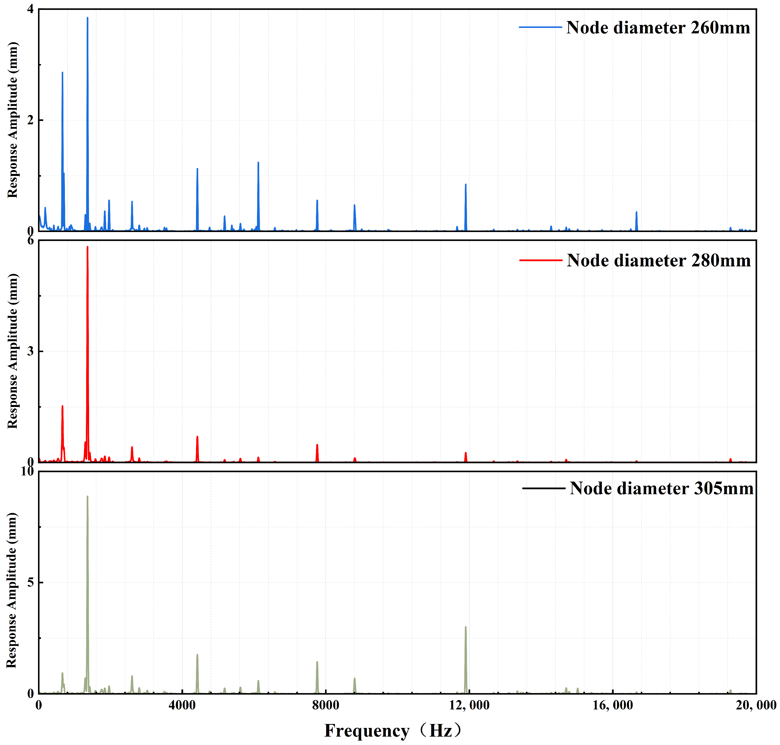
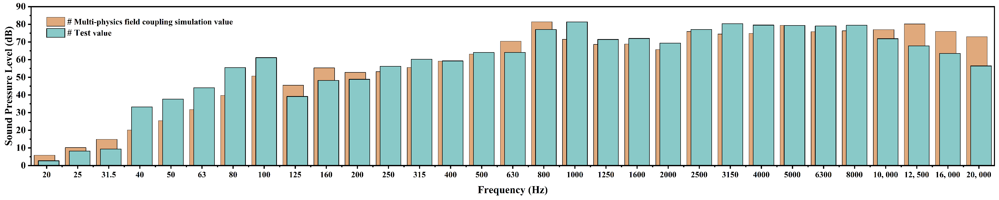
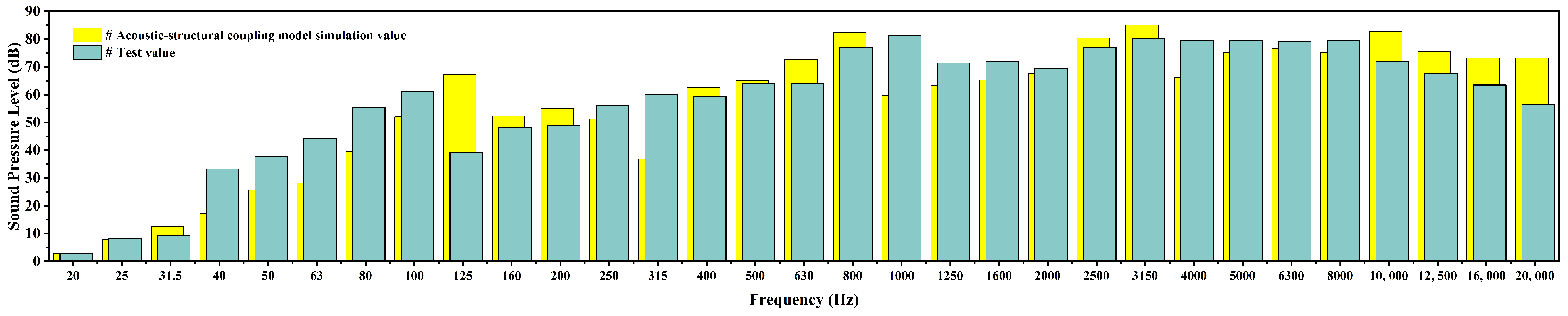
5.2. Noise Frequency Domain Response Analysis

The measured noise in the experimental results consists of ambient noise (e.g., machine tool and exhaust equipment noise) and saw blade operational noise (including both idling and sawing noise). Therefore, it is essential to isolate the noise components associated with the sawing process from the total sound pressure level. In this study, logarithmic superposition and separation of the measured sound pressure levels were performed using MATLAB R2021a to extract the frequency-domain information representing the net contribution of sawing noise [37]. The noise measurement result at a distance of 1 m from the origin, with the measurement point located at a 90-degree position, is shown in Table 4.
Under sawing conditions, random small-amplitude fluctuations combine with multiple frequency components, resulting in a broad-band distribution in the sawing noise spectrum. The excitation frequencies of saw blade vibrations include the rotation frequency, disturbance frequency, tooth pass frequency, and their higher harmonics, spanning a broad spectral range from low to high frequencies [38]. The equivalent sound pressure level (LAeq,T) of the sawing noise is 89.3 dB, significantly higher than both the idling noise (80.2 dB) and ambient noise (76.6 dB), confirming that the sawing process is the primary noise source. The frequency-domain characteristics are summarized as follows:
➀ In the low-frequency band (f < 500 Hz), the sound pressure level is relatively low, mainly due to the rigid body motion induced by the saw blade’s rotational frequency. Its impact on acoustic radiation is minimal, resulting in low radiation efficiency. ➁ In the mid-frequency band (500 Hz to 8000 Hz), the excitation frequency includes the tooth passing frequency. The periodic vibration caused by the contact between the teeth and the material is significantly amplified, leading to a rapid increase in sound pressure level. High-order modal vibrations are excited, contributing to a peak in the sound pressure level, making this the main source of noise. ➂ In the high-frequency band (8000 Hz to 20 kHz), the sound pressure level shows a clear attenuation trend, indicating that vibration excitation in this range is minimal, failing to generate significant vibrational responses.
To visually represent the spatial distribution of cutting noise, a near-field sound pressure map of the saw blade was generated from the multi-physical field coupling (Figure 8). Additionally, the contribution of modes 91 to 100 to the sound pressure level is displayed (Figure 9).
The simulation results indicate that the sound pressure distribution of the circular saw blade is highly frequency-dependent. Under low-frequency excitation (e.g., 200 Hz), the sound field distribution is relatively uniform, with a lower overall sound pressure level and obscure directivity. In this range, the saw blade primarily undergoes low-order modal vibrations, with low radiation efficiency, which mainly affects the dynamic stability. Conversely, as the frequency moves into the middle and high ranges, the sound pressure level increases significantly. The sound field distribution becomes complex and non-uniform, with higher-order modal vibrations contributing more to acoustic radiation, thus increasing sawing noise.
Figure 10 and Figure 11 show the comparison of the multi-physical field coupled simulation and pure sound field simulation results with the experimentally extracted net sawing noise SPL data, with the measurement point located at 1 m and a 90-degree angle, respectively. The results show that the multi-physical field coupling simulation results are highly consistent with the experimental data in terms of the overall distribution trend, particularly in the mid-frequency range (500 Hz–8000 Hz), where the error is extremely small. It shows that the accuracy of the multi-physical field coupling simulation in the prediction of the frequency-domain characteristics of sawing noise is significantly improved. Further improvements can be achieved by investigating material damping characteristics, calibrating environmental background noise and analyzing the attenuation characteristics of high-frequency acoustic waves, so as to further reduce the simulation errors at low and high frequencies.

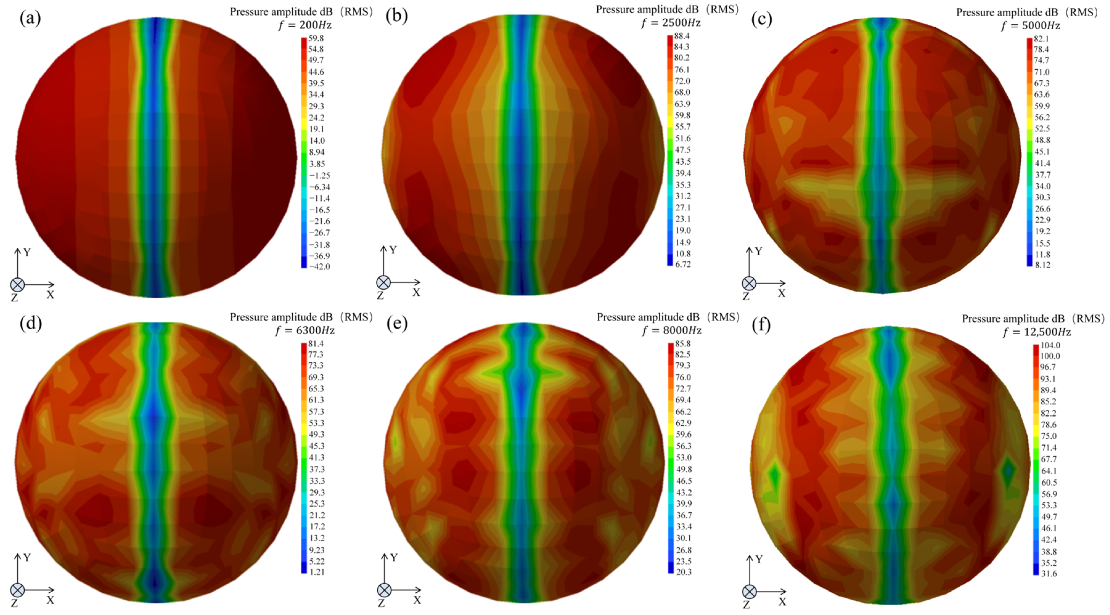
5.3. Noise Spatial Distribution Analysis

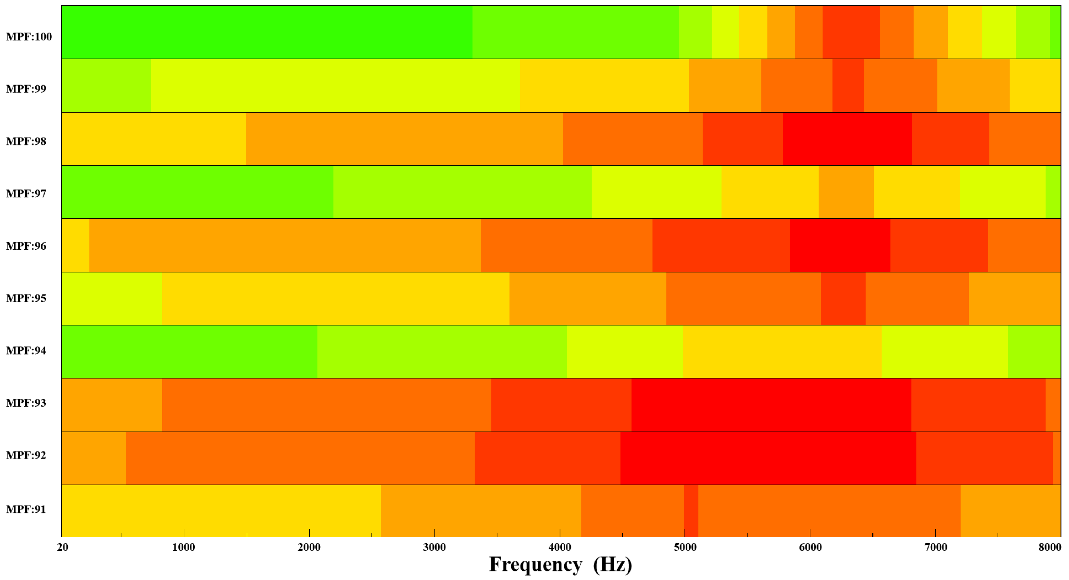
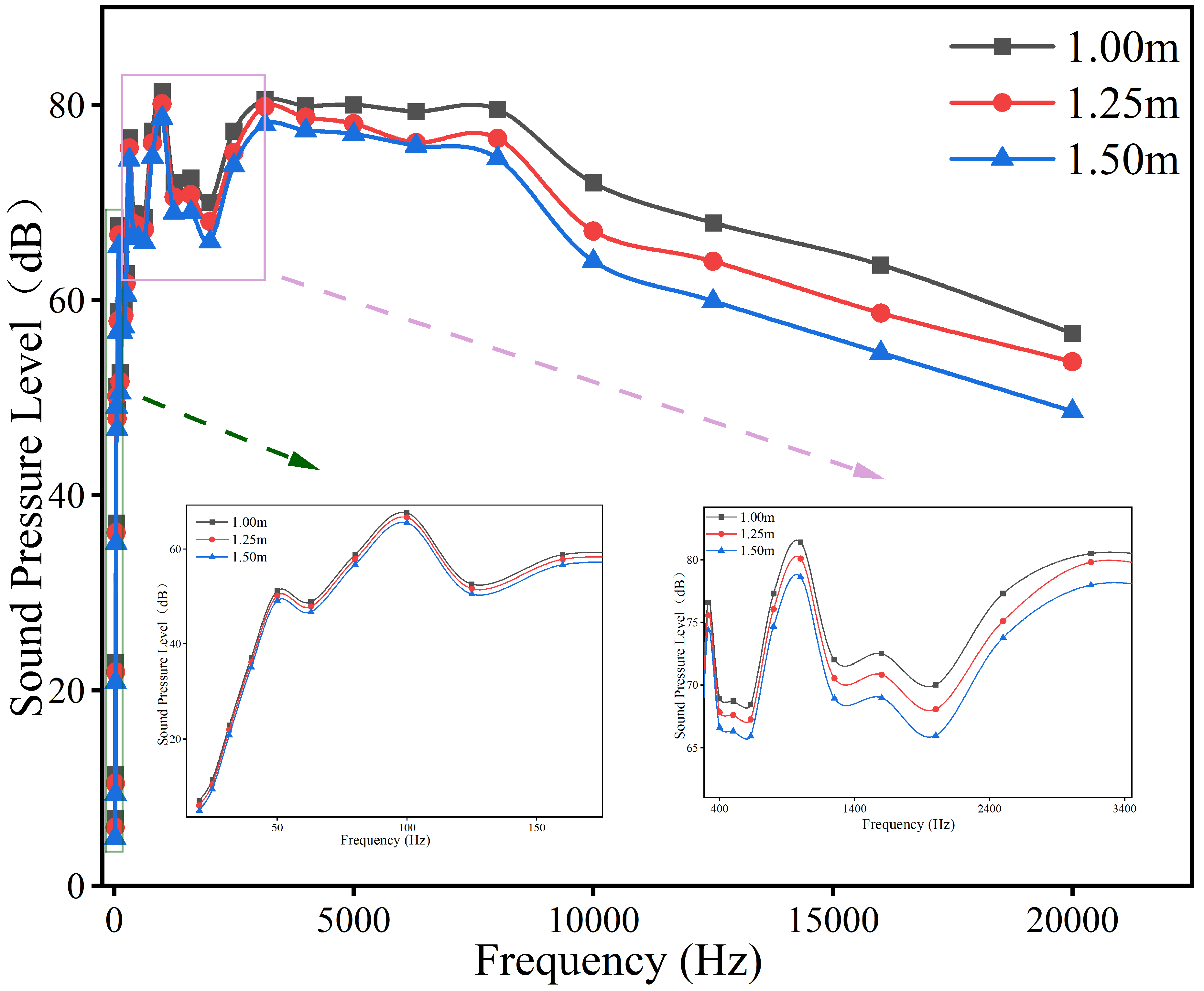
5.3.1. Spatial Sound Field Attenuation Analysis

Due to the large error of the simple acoustic field simulation, the following section mainly analyzes the noise radiation characteristics of the multi-physics field coupling simulation. During sound wave propagation, diffusion, absorption, and scattering by the medium cause gradual attenuation of the sound pressure level. Compared to liquids and solids, gases result in faster attenuation due to their higher absorption properties [39]. To investigate the attenuation characteristics of a woodworking circular saw blade in a spatial sound field, spectral measurements of sawing noise were taken at 90-degree points with radii of 1.0 m, 1.25 m, and 1.5 m. The results are shown in Figure 12.
As the measurement distance increased from 1.0 m to 1.5 m, the sound pressure levels at all frequencies exhibited varying degrees of attenuation, with greater attenuation observed at higher frequencies. In the low-frequency range (f < 500 Hz), attenuation was minimal, indicating that low-frequency sound waves have strong propagation capabilities and low absorption coefficients. Due to their longer wavelengths, low-frequency sound waves are less affected by absorption and scattering in the air, resulting in lower propagation loss. In the mid-frequency range (500 Hz to 8000 Hz), attenuation became more pronounced, while in the high-frequency range (8000 Hz to 20 kHz), sound pressure levels decreased sharply. This is mainly due to the increased absorption and scattering of high-frequency sound waves by the medium during propagation, leading to higher propagation loss [40].

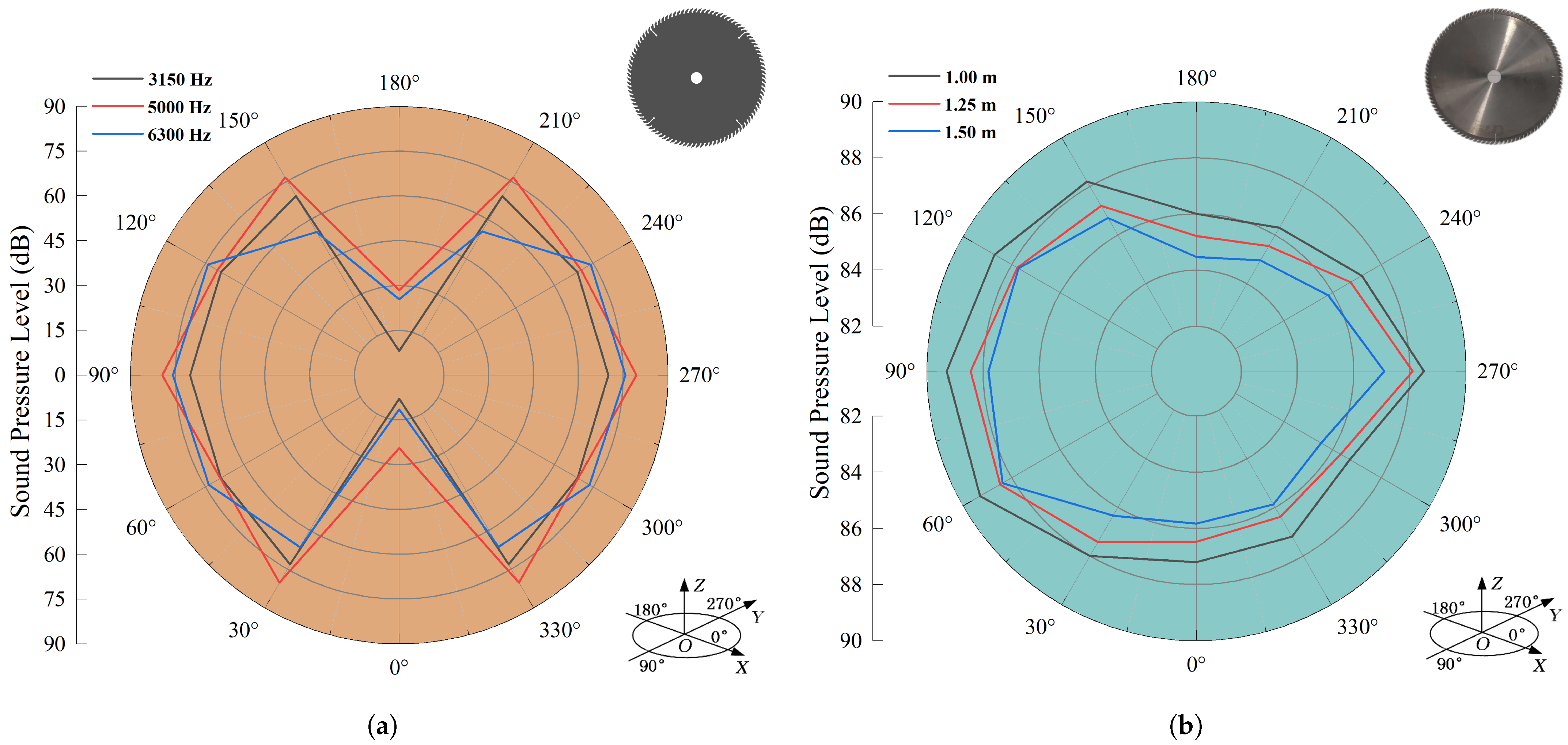
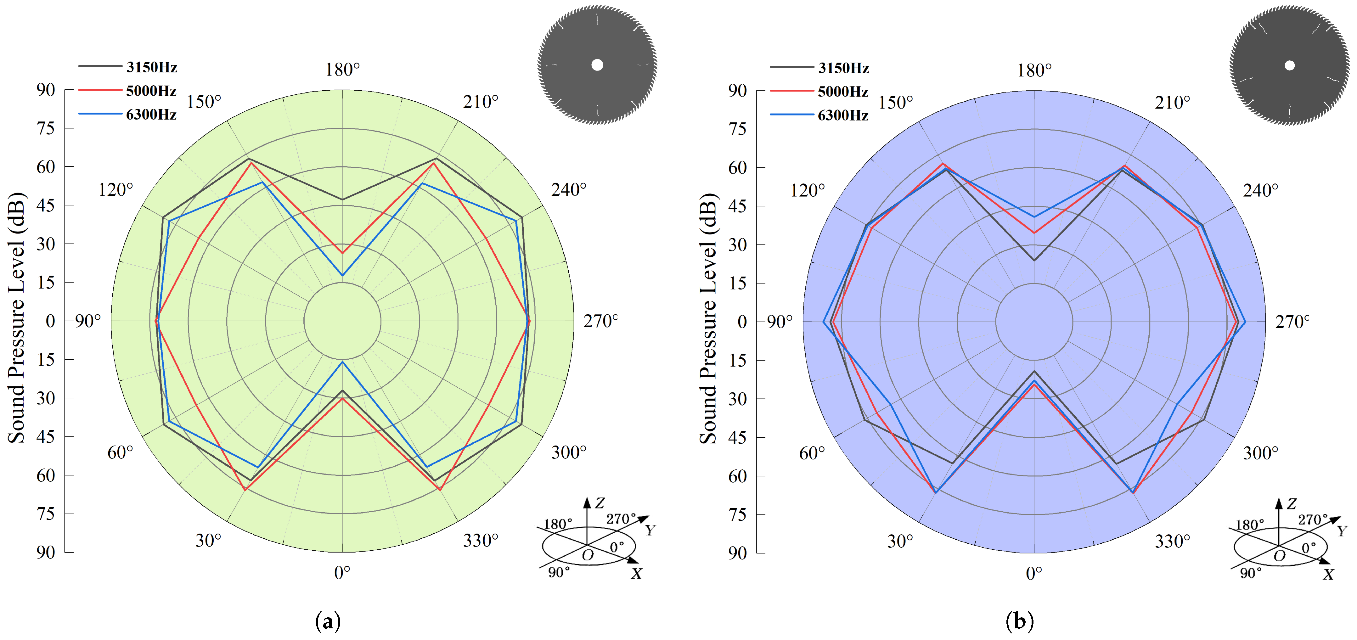
5.3.2. Noise Directionality Analysis

Noise directivity describes the spatial distribution of sound pressure at the same distance but in different directions [40]. As shown in Table 4, frequencies such as 3150 Hz, 5000 Hz, and 6300 Hz have a more significant impact on noise radiation. In this study, a radius of 1 m was chosen for the directivity analysis, and the results were derived from the numerical simulation of transverse vibration noise, as shown in Figure 13a.
Based on the measurement point arrangement in Figure 6, the test was repeated three times under identical conditions to obtain the average sound pressure value for each point. In the test, measurement points between 0° and 90° and between 90° and 180° were located near the machine tools and exhaust equipment, resulting in higher ambient noise levels. Consequently, noise values in these directions were higher than those in the 180° to 270° and 270° to 360° intervals. The results are shown in Figure 13b.
The numerical simulation results indicate that the sound pressure level of sawing noise is relatively low in the direction parallel to the saw blade (i.e., at 0° and 180° measurement points). The sound pressure levels in other directions exhibit minimal variation, with an overall symmetrical distribution primarily along the X and Y axes. This phenomenon can be attributed to the flange constraint on the circular saw blade, which reduces the axial vibration amplitude. Additionally, the symmetry of the circular saw blade model causes some sound pressure to cancel each other out along the axis, resulting in a lower sound pressure level in the parallel direction compared to other positions. The sound pressure levels in other directions are primarily influenced by the superposition of various vibration modes, resulting in variations under different frequency excitations.
Experimental results indicate that the directivity difference of the measured noise at various directions and distances is not significant, suggesting that sawing noise is a multi-source superposition type of processing noise. Apart from environmental noise, the high-speed rotation of the circular saw blade induces strong vibration in the air mass on the end surface, generating quadrupole radiation. Additionally, the air vortex flowing along the blade surface creates dipole radiation, while the air moving along the tooth tip generates monopole radiation [41,42,43]. Consequently, the complex noise characteristics arising from this multi-source superposition make it challenging to accurately capture the noise directivity in experimental measurements.
A comprehensive analysis reveals that relying solely on experimental measurements for noise directivity research is challenging. In contrast, the multi-physical field coupling method effectively isolates the direct contribution of saw blade vibration to noise radiation, overcoming the limitations imposed by multi-source noise superposition and environmental interference. The simulation results not only reveal the directivity characteristics of the noise and its intrinsic connection with vibration modes, but also provide an essential theoretical foundation and technical support for optimizing saw blade design and suppressing vibration noise.

5.4. Noise Reduction Design Method Based on Noise Radiation Characteristics

(1) Noise reduction slot
Saw blade noise can be effectively reduced by altering the inherent characteristics of the circular saw blade [44]. While damping materials are effective for noise reduction, their use significantly increases production costs. For ultra-thin woodworking circular saw blades, which are susceptible to transverse vibrations, a cost-effective solution for noise reduction involves designing a noise reduction slot to reduce overall vibration intensity.
The authors’ team developed an optimization design procedure for the noise reduction slot of ultra-thin circular saw blades, using a combined MATLAB–ANSYS simulation method and a multi-objective genetic optimization algorithm. This method allows for the determination of the optimal shape parameters of the noise reduction slot while ensuring the saw blade’s safety. The optimization design approach has been published in the literature [28]. Using this method, the team completed the design of circular saw blades with four and five noise reduction slots. Experimental results show that these blades achieved a noise reduction of approximately 3 dB, with a significant decrease in the radiated energy in the mid-frequency acoustic field.
Building on this, the team conducted acoustic–structural coupling simulations for the circular saw blade with noise reduction slots and obtained results on its acoustic field directivity distribution, shown in Figure 14.
The following conclusions can be drawn from the analysis: ➀ The core objective of designing the noise reduction slots is to optimize their shape parameters in a way that reduces the overall vibration intensity of the saw blade in the mid- and high-frequency ranges while maintaining the blade’s stiffness. ➁ For small-sized woodworking circular saw blades, varying the number of noise reduction slots has little impact on the noise reduction effectiveness, suggesting that within a certain range, increasing the number of slots has a limited effect on improving noise reduction. ➂ The introduction of noise reduction slots alters the structural symmetry of the circular saw blade, affecting its modal distribution characteristics. This change leads to a shift in the directivity of the noise generated by transverse vibrations at certain angles, although the overall distribution remains symmetric.
(2) Sound barrier
Sound barrier technology is widely used in the field of noise control, mainly through the establishment of physical obstacles between the noise source and the receiving area, to limit the propagation path of noise, so as to effectively reduce the spread of environmental noise. The noise reduction mechanism of sound barriers relies on the attenuation, reflection, and scattering of sound waves, which prevents the noise waves from reaching the receiving area, especially in the suppression of high-frequency noise, which has obvious advantages. The choice of materials and the structural morphology of the sound barrier have a crucial influence on its sound absorption performance and noise reduction efficiency [45].
The multi-physical field coupling simulation method proposed in this study lays the foundation for acoustic performance analysis for sound barrier design. Specifically, by setting the acoustic field boundary in the acoustic–solid coupling analysis as the sound barrier structure, the designer can quickly evaluate the noise reduction effect among multiple design options, and then make structural optimization adjustments to ensure the economy and practicability of the sound barrier design.

6. Conclusions

In this study, a multi-physics field coupling simulation model of circular saw blade sawing noise radiation characteristics is developed using FEM/BEM joint simulation technology. The model’s noise radiation characteristics are systematically analyzed by combining modal experiments and noise tests. The main conclusions are as follows:
  • The multi-physics field coupling simulation model, based on theoretical analysis of sawing vibration noise, demonstrates high consistency with experimental data, validating its accuracy in predicting the frequency-domain characteristics and spatial distribution of sawing noise.
  • Sawing noise shows clear frequency dependence. In the low-frequency band (f < 500 Hz), the acoustic field is uniformly distributed with low radiation efficiency, primarily affecting the dynamic stability of the circular saw blade. In the mid-frequency band (500 Hz–8000 Hz), the cyclic vibration of the saw teeth in contact with the material significantly increases, leading to a rapid rise in sound pressure levels. Higher-order modal vibrations excite a more complex acoustic field distribution, which is the primary source of noise. In the high-frequency band (8000 Hz–20 kHz), sound pressure levels attenuate significantly due to reduced vibration excitation, increased medium absorption, and other factors, resulting in low radiation efficiency.
  • The simulation results show distinct vibration noise directivity at different excitation frequencies. The direction parallel to the saw blade (0° and 180° measurement points) exhibits lower sound pressure levels, while other directions show higher but more consistent levels. Overall, the distribution is symmetrical in the X and Y directions. However, experimental measurements reveal multi-source superposition of processing noise with less distinct directivity.
  • In-depth analysis of sawing noise radiation characteristics provides theoretical guidance for the design of noise reduction strategies for circular saw blades. The incorporation of noise reduction slots effectively suppresses noise in the mid-frequency range, while sound barrier structures significantly reduce the propagation of high-frequency noise.
Currently, the multi-physics field coupling simulation model based on FEM/BEM has yielded preliminary results. Future improvements could involve incorporating additional physical fields, such as the flow field, to enhance the model’s applicability and accuracy in complex working conditions. Additionally, integrating the actual production environment, the cost–benefit analysis of noise control technology implementation should be conducted to assess the economic feasibility of different noise reduction strategies, including implementation costs, resource savings, and potential long-term social and economic benefits. This will provide more feasible and effective noise reduction solutions for circular saw blades.

Author Contributions

N.J. and L.G.; methodology, L.G.; software, L.G.; validation, N.J. and L.G.; formal analysis, Y.Z.; investigation, N.J.; resources, Y.Z.; data curation, L.G.; writing—original draft preparation, L.G.; writing—review and editing, N.J.; visualization, J.L.; supervision, J.L.; project administration, J.L.; funding acquisition. All authors have read and agreed to the published version of the manuscript.

Funding

This work was supported by Central Guidance on Local Technology Development Special Fund: Application and Industrialization of Pure Grade Electrical Laminated Wood Preparation Technology [Grant No. ZY23CG18].

Data Availability Statement

Data will be made available on request.

Conflicts of Interest

The authors declare no conflicts of interest.

References

  1. Kvietková, M.; Gaff, M.; Gašparík, M.; Kminiak, R.; Kriš, A. Effect of number of saw blade teeth on noise level and wear of blade edges during cutting of wood. BioResources 2015, 10, 1657–1666. [Google Scholar] [CrossRef]
  2. Kang, J.; Zhang, H.; Zhang, J.; Yuan, X.; Lv, C.; Bai, T.; Gong, Y.; Guo, J. Development of a novel circular saw blade substrate with high stiffness for mitigating vibration noise and improving sawing performance. Mech. Syst. Signal Process. 2025, 223, 111934. [Google Scholar] [CrossRef]
  3. Stevenson, D.; Gray, W.; Hoong, K.; Speller, M. Quietening circular saws by reducing blade vibration. Noise Control. Eng. J. 1989, 33, 33–36. [Google Scholar] [CrossRef]
  4. Svoren, J.; Javorek, L.; Murin, L. Effect of the shape of compensating slots in the body of a circular saw blade on noise level in the cutting process. Pro Ligno 2010, 6, 5–12. [Google Scholar]
  5. Droba, A.; Javorek, L.; Svoren, J.; Paulíny, D. New design of circular saw blade body and its influence on critical rotational speed. Drew. Pr. Nauk. Doniesienia Komun. 2015, 58, 147–157. [Google Scholar] [CrossRef]
  6. Svoreň, J.; Naščák, L.; Koleda, P.; Barcík, Š.; Němec, M. The circular saw blade body modification by elastic material layer effecting circular saws sound pressure level when idling and cutting. Appl. Acoust. 2021, 179, 108028. [Google Scholar] [CrossRef]
  7. Chang, W.T.; Chen, L.C. Design and experimental evaluation of a circular saw blade with self-clamped cutting inserts. Int. J. Adv. Manuf. Technol. 2016, 83, 365–379. [Google Scholar] [CrossRef]
  8. Takeyama, K.; Yokochi, H.; Nishio, S.; Tsuchikawa, S. Characteristics of Resonance Sound in a Circular Saw Enclosure. BioResources 2023, 18. [Google Scholar] [CrossRef]
  9. Szymani, R.; Mote, C. Principal developments in thin circular saw vibration and control research: Part 2: Reduction and control of saw vibration. Holz Als-Roh-Und Werkst. 1977, 35, 219–225. [Google Scholar] [CrossRef]
  10. Wang, C.Y.; Hu, Y.N.; Wang, Z.; Ding, H. Noise and vibration of diamond sawblade for concrete dry cutting. Key Eng. Mater. 2005, 291, 103–108. [Google Scholar] [CrossRef]
  11. Martin, B.; Bies, D. On aerodynamic noise generation from vortex shedding in rotating blades. J. Sound Vib. 1992, 155, 317–324. [Google Scholar] [CrossRef]
  12. Leu, M.; Mote, C. Origin of idling noise in circular saws and its suppression. Wood Sci. Technol. 1984, 18, 33–49. [Google Scholar] [CrossRef]
  13. Citarella, R.; Federico, L.; Cicatiello, A. Modal acoustic transfer vector approach in a FEM–BEM vibro-acoustic analysis. Eng. Anal. Bound. Elem. 2007, 31, 248–258. [Google Scholar] [CrossRef]
  14. Chen, L.; Lian, H.; Pei, Q.; Meng, Z.; Jiang, S.; Dong, H.W.; Yu, P. FEM-BEM analysis of acoustic interaction with submerged thin-shell structures under seabed reflection conditions. Ocean. Eng. 2024, 309, 118554. [Google Scholar] [CrossRef]
  15. Minciunescu, P.; Marinescu, S.; Hănţilă, F.; Drosu, O.M. FEM-BEM technique for solving the magnetic field in electric machines. Rev. Roum. Sci. Techn. Électrotechn. et Énerg 2011, 56, 189–198. [Google Scholar]
  16. Maeder, M.; D’Auria, R.; Grasso, E.; Petrone, G.; De Rosa, S.; Klaerner, M.; Kroll, L.; Marburg, S. Numerical analysis of sound radiation from rotating discs. J. Sound Vib. 2020, 468, 115085. [Google Scholar] [CrossRef]
  17. Yao, T.; Duan, G.; Wang, T. Coupled FEM/BEM Method for Noise Prediction of Common and Sandwich Circular Saw Blades. Key Eng. Mater. 2016, 693, 463–470. [Google Scholar] [CrossRef]
  18. Tian, Y.; Duan, G.; Xia, X.; Zhang, E. Optimization Design of Low Noise Circular Saw Parameters Combining Response Surface Model with Hybrid Optimization Algorithm. China Mech. Eng. 2016, 27, 3025. [Google Scholar]
  19. Li, Z.; Yu, H.; Bai, Y. Numerical simulation of CO2-ECBM based on multi-physical field coupling model. Sustainability 2022, 14, 11789. [Google Scholar] [CrossRef]
  20. Wang, Q.; Zhang, X.; Wang, D.; Cui, H.; Zhang, S.; Wang, J. Numerical simulation and experimental investigation on the thermal-fluid-solid multi-physical field coupling characteristics of wet friction pairs considering cavitation effect. Appl. Therm. Eng. 2025, 260, 124955. [Google Scholar] [CrossRef]
  21. Wang, Y.; Xu, Z.; Meng, D.; Liu, L.; Fang, Z. Multi-Physical Field Coupling Simulation and Experiments with Pulse Electrochemical Machining of Large Size TiAl Intermetallic Blade. Metals 2023, 13, 985. [Google Scholar] [CrossRef]
  22. Tian, Y.; Duan, G.; Xia, X.; Zhang, E. Calculations and Analyseis on Aerodynamic Noise Characteristics of Rotating Saw Blades. China Mech. Eng. 2017, 28, 272. [Google Scholar]
  23. Kang, J.; Zhang, H.; Zhang, J.; Wang, K.; Bai, T. Dynamic response of circular saw blade based on dynamic sawing force model in machining hard aluminum alloys. Measurement 2024, 231, 114616. [Google Scholar] [CrossRef]
  24. Li, S.; Wang, C.; Zheng, L.; Wang, Y.; Xu, X.; Ding, F. Dynamic stability of cemented carbide circular saw blades for woodcutting. J. Mater. Process. Technol. 2016, 238, 108–123. [Google Scholar] [CrossRef]
  25. Mote Jr, C. Stability of circular plates subjected to moving loads. J. Frankl. Inst. 1970, 290, 329–344. [Google Scholar] [CrossRef]
  26. Wang, Z.; Wu, S.F. Helmholtz equation–least-squares method for reconstructing the acoustic pressure field. J. Acoust. Soc. Am. 1997, 102, 2020–2032. [Google Scholar] [CrossRef]
  27. Peng, T.; Hou, F.; Zou, X.; Qi, Z.; Han, X. Acoustic insulation performance of laminated plates based on equivalent FE-BEM method. J. Aerosp. Power 2024, 39, 14–21. [Google Scholar]
  28. Jia, N.; Guo, L.; Wang, R.; Liu, J. Design of vibration and noise reduction for ultra-thin cemented carbide circular saw blades in woodworking based on multi-objective optimization. Forests 2024, 15, 1554. [Google Scholar] [CrossRef]
  29. Ding, Y.; Ma, Y.; Liu, T.; Zhang, J.; Yang, C. Experimental Study on the Dynamic Stability of Circular Saw Blades during the Processing of Bamboo-Based Fiber Composite Panels. Forests 2023, 14, 1855. [Google Scholar] [CrossRef]
  30. Czajkowski, Ł.; Olek, W.; Weres, J.; Guzenda, R. Thermal properties of wood-based panels: Specific heat determination. Wood Sci. Technol. 2016, 50, 537–545. [Google Scholar] [CrossRef]
  31. Svoreň, J.; Javorek, L.; Krajčovičová, M.; Klobušiaková, K.; Kubovskỳ, I.; Kminiak, R. The effect of the circular saw blade body structure on the concentric distribution of the temperature along the radius during the wood cutting process. Wood Res. 2017, 62, 427–436. [Google Scholar]
  32. Rieß, S.; Kaal, W.; Herold, S. Vibration reduction on circular saw blades with vibroacoustic metamaterials. Bull. Pol. Acad. Sci. Tech. Sci. 2023, 71. [Google Scholar] [CrossRef]
  33. Yu, J.; Zhang, J.; Wang, Z.; Ye, L.; Ge, J.; Gao, L. Study on the hole shape of diamond circular saw blades with noise reduction holes based on FEM/BEM. Diam. Abrasives Eng. 2016, 36, 63–67+74. [Google Scholar]
  34. Pastor, M.; Binda, M.; Harčarik, T. Modal assurance criterion. Procedia Eng. 2012, 48, 543–548. [Google Scholar] [CrossRef]
  35. Krilek, J.; Kováč, J.; Barcík, Š.; Svoreň, J.; Štefánek, M.; Kuvik, T. The influence of chosen factors of a circular saw blade on the noise level in the process of cross cutting wood. Wood Res. 2016, 61, 475–486. [Google Scholar]
  36. Fotsch, D.; Ewins, D. Application of MAC in the Frequency Domain. Rolls Royce PLC-Report-PNR. 2000. Available online: https://citeseerx.ist.psu.edu/document?repid=rep1&type=pdf&doi=93c56831cfee2f33937b8a1202069f503c516a09 (accessed on 22 January 2025).
  37. Wu, S.F. Methods for reconstructing acoustic quantities based on acoustic pressure measurements. J. Acoust. Soc. Am. 2008, 124, 2680–2697. [Google Scholar] [CrossRef]
  38. Ma, J.; Lü, J.; Huang, X.; Chen, T. Estimation of sound power of noise from large cold saw machines. J. Appl. Mech. 2001, 3, 28–32+148. [Google Scholar]
  39. Attenborough, K. Sound propagation in the atmosphere. Springer Handbook of Acoustics; Springer: Berlin/Heidelberg, Germany, 2014; pp. 117–155. [Google Scholar]
  40. Chatillon, J. Influence of source directivity on noise levels in industrial halls: Simulation and experiments. Appl. Acoust. 2007, 68, 682–698. [Google Scholar] [CrossRef]
  41. Cho, H.; Mote, C., Jr. On the aerodynamic noise source in circular saws. J. Acoust. Soc. Am. 1979, 65, 662–671. [Google Scholar] [CrossRef]
  42. Stewart, J.S. An investigation of the aerodynamic noise generation mechanism of circular saw blades. Noise Control. Eng. 1978, 11, 5–11. [Google Scholar] [CrossRef]
  43. Reiter, W., Jr.; Keltie, R. On the nature of idling noise of circular saw blades. J. Sound Vib. 1976, 44, 531–543. [Google Scholar] [CrossRef]
  44. Pohl, M.; Rose, M. Piezoelectric shunt damping of a circular saw blade with autonomous power supply for noise and vibration reduction. J. Sound Vib. 2016, 361, 20–31. [Google Scholar] [CrossRef]
  45. Zhao, W.; Chen, L.; Zheng, C.; Liu, C.; Chen, H. Design of absorbing material distribution for sound barrier using topology optimization. Struct. Multidiscip. Optim. 2017, 56, 315–329. [Google Scholar] [CrossRef]
Figure 1. Multi-physical field coupling simulation process.
Forests 16 00442 g001
Figure 2. Thermal conduction simulation setup and results.
Forests 16 00442 g002
Figure 3. Mode shapes of circular saw blade for various nodal circles and nodal diameters.
Forests 16 00442 g003
Figure 4. Acoustic simulation models.
Forests 16 00442 g004
Figure 5. Modal test procedure and results.
Forests 16 00442 g005
Figure 6. Noise experiment site, schematic, and distribution of measurement points.
Forests 16 00442 g006
Figure 7. Vibration response spectrum of circular saw blade at different nodes.
Forests 16 00442 g007
Figure 8. Sound field cloud of circular saw blade under different frequency excitation.
Forests 16 00442 g008
Figure 9. SPL contribution distribution of partial modal participation factors.
Forests 16 00442 g009
Figure 10. Comparison of frequency-domain sound pressure levels of multi-physics field coupling: simulated and experimental.
Forests 16 00442 g010
Figure 11. Comparison of frequency-domain sound pressure levels of the acoustic–structural coupling model: simulated and experimental.
Forests 16 00442 g011
Figure 12. Spectrum noise of circular saw blade at different distances.
Forests 16 00442 g012
Figure 13. Comparison of simulated and experimental noise directivity. (a) Simulation directivity, (b) Test directivity.
Forests 16 00442 g013
Figure 14. Noise directivity of circular saw blade with noise reduction slots. (a) Circular saw blade with 4 noise reduction slots, (b) Circular saw blade with 5 noise reduction slots.
Forests 16 00442 g014
Table 1. Material properties of saw body and teeth.
MaterialsSKS51 (Saw Body)YG6 (Serrated)
Density (kg/m3)785014,800
Poisson’s ratio0.280.30
Modulus of elasticity (GPa)210510
Coefficient of thermal expansion (1/K) 11.2 × 10 6 6.0 × 10 6
Specific heat (J/kg·°C)460220
Thermal conductivity (W/mK)51.975.0
Table 2. Thermal and mechanical properties of particleboard.
PropertyDensity (g/cm3)Poisson’s RatioModulus of Elasticity (MPa)Bending Strength (MPa)Coefficient of Thermal Expansion (1/K)Specific Heat (J/kg·°C)Thermal Conductivity (W/mK)
Chipboard0.650.34250479 6.9 × 10 6 38410.165
Table 3. Comparison of modal natural frequencies.
OrderTest Value/HzSimulation Value/HzInaccuracy/%OrderTest Value/HzSimulation Value/HzInaccuracy/%
151.6651.450.416171.28183.236.52
256.1451.598.827190.69183.244.07
367.9662.558.658297.06316.486.14
483.4883.351.569319.37319.770.13
589.8183.617.4210334.99362.777.66
Table 4. Noise frequency-domain information.
Environmental Noise (dB)Idling Noise (dB)Sawing Noise (dB)Net Sawing Noise (dB)
20 Hz4.74.86.92.74
25 Hz8.18.511.48.28
31.5 Hz21.822.622.89.33
40 Hz34.534.837.133.24
50 Hz50.850.951.137.63
63 Hz45.847.048.844.11
80 Hz54.656.158.855.46
100 Hz62.466.567.661.10
125 Hz52.152.452.639.13
160 Hz58.158.458.848.24
200 Hz58.559.059.448.84
250 Hz59.461.662.756.20
315 Hz69.376.576.660.17
400 Hz67.768.468.959.26
500 Hz66.066.968.764.01
630 Hz65.866.468.464.07
800 Hz64.864.977.377.04
1000 Hz62.763.081.481.34
1250 Hz62.962.972.071.43
1600 Hz62.962.972.572.00
2000 Hz60.261.270.069.39
2500 Hz61.164.177.377.09
3150 Hz60.667.080.580.30
4000 Hz57.168.879.979.55
5000 Hz51.971.480.079.35
6300 Hz50.166.479.379.07
8000 Hz48.060.979.579.44
10,000 Hz40.157.472.071.85
12,500 Hz33.652.867.967.76
16,000 Hz30.448.163.663.48
20,000 Hz26.842.656.656.42
LAmax78.581.092.0
LAmin75.379.687.2
LAeq,T76.680.289.3
Disclaimer/Publisher’s Note: The statements, opinions and data contained in all publications are solely those of the individual author(s) and contributor(s) and not of MDPI and/or the editor(s). MDPI and/or the editor(s) disclaim responsibility for any injury to people or property resulting from any ideas, methods, instructions or products referred to in the content.

