Article

Manufacturing and Testing the Panels with a Transverse Texture Obtained from Branches of Norway Spruce (Picea abies L. Karst.)

Wood Processing and Design Wooden Product Department, Transilvania University of Brasov, 29 Street Eroilor, 500036 Brasov, Romania
*
Author to whom correspondence should be addressed.
Forests 2023, 14(4), 665; https://doi.org/10.3390/f14040665
Submission received: 13 February 2023 / Revised: 13 March 2023 / Accepted: 20 March 2023 / Published: 23 March 2023
(This article belongs to the Special Issue Novelties in Wood Engineering and Forestry)

Abstract

:
As a result of the imbalances in the forestry market and the increased demand for wood products worldwide, the resource of branches resulting from the exploitation of a forest has attracted special attention from researchers, in order to use these secondary resources judiciously and obtain an added value superior to classic uses. In this context, the current research took into consideration the use of spruce branches to obtain panels with a transverse structure. The work methodology has focused on the process of obtaining panels with a transverse texture and on determining the physical–mechanical properties of the created panels. The results regarding the panel density (determined as a ratio between mass and volume of specimens) showed about 693 kg/m3, static bending resistance parallel to the face of 5.5 N/mm2, resistance of adhesion of 5.6 N/mm2, shear strength parallel to face of 4.1 N/mm2, and screw pull-out resistance perpendicular to the face of 31.3 N/mm2, highlighting that the properties were in accordance with the European standards and that the panels obtained were suitable for obtaining furniture products with a special aesthetic aspect. As a general conclusion of the research, it can be stated that spruce branches are a sustainable wood resource with great possibilities to add more value in the form of panels with a traverse texture.

1. Introduction

The lack or insufficiency of forest resources in recent decades has determined the search for new solutions to replace solid wood in the form of timber or logs. The branches obtained from the exploitation of a forest, be they coniferous or deciduous, has been considered for a long period of time as forest biomass [1], with exclusive uses in combustion and in the technology of composite boards made of chips and wood fibers [2,3,4]. In the last four decades, tree branches have been studied more and more [5,6,7,8] in order to better know their properties and implicitly understand their uses [9]. It was found that the branches have the same structure as the trunk wood [10], with the exception of the reaction wood, particularized in compression wood for softwoods or tension in the case of hardwoods, whose properties are slightly different from the trunk wood.
The large amount of wood from the branches of a tree, estimated at about 10% of the total volume of the trunk, shows that when exploiting a forest area, an impressive volume of wood is available, with physical and mechanical properties close to those of the trunk [11,12,13]. These branches must be used judiciously and economically efficiently in order to obtain the greatest possible added value, superior to that obtained in the case of use in the field of wood-based composites.
Regarding the design of a new product, the sustainability of the raw material must be taken into account as well as the fact that the products obtained should be cleaner and greener. In recent years, the importance of environmental aspects has increased [14], which is why the product eco-design has become one of the most important conditions for the development of new products. Some of the criteria mentioned in the research of some authors [15,16,17,18,19,20] are the acquisition of secondary resources such as woody biomass, the choice of materials with a low impact on the environment and the development of products with a high added value. Therefore, through this eco-design (or ecological product design), the design of the new product is brought into line with the environment, both during the product’s functionality and after its removal from use.
Wood-based panels are part of the boards category, including particleboard, fiberboard, oriented strand board (OSB), medium-density fiberboard (MDF), plywood, laminated veneer lumber (LVL), glue laminated products (Glulam), cross laminated timber (CLT), etc. That is why the tests for determining the physical–mechanical properties of wood-based panels are the same as those of the previously mentioned boards. Depending on their field of use of EN 13353: 2022, a wetting treatment via immersion was recommended before performing some tests [21] such as gluing resistance, modulus of rupture (MOR), and modulus of elasticity (MOE) in bending strength (EN 300: 2019 for OSB and EN 312: 2010 for particleboard) (Table 1).
The analysis of previous research in the field of the theme highlights the fact that they studied the properties of wood from branches. Based on these properties, some future uses are predicted. The use of wood from branches in the field of wood-based composite materials is the most common because they are reconstituted engineering products, which even out the structural inhomogeneity of this wood. Starting from these limitations, the current research aimed to highlight the special structure of the cross-sectional area of the wood from the branches by creating a panel that can be used in small furniture. The objectives of this study are to present the optimal technology for manufacturing panels with a transverse texture obtained from spruce (Picea abies L.) branches and test these panels. The research started from the hypothesis that the structural inhomogeneity of the wood from the branches will be mitigated by gluing the friezes with a suitable adhesive, and the adequate technology of the panel with a traverse structure will remove any cracks that may appear during the use of the finished product.

2. Materials and Method

Technology of manufacturing and plan of panel testing. The manufacture of panels with a transverse texture from branches includes several phases, such as sorting them in order to choose the appropriate branches, cutting the prisms, forming the blocks of prisms by gluing on the edge, cutting the block into transverse friezes, forming a panel from transverse friezes by applying adhesive on the edge and pressing them, panel processing via formatting and calibration, panel packaging via wrapping, and panel storage (Figure 1).
Due to the small dimensions of the 6-dimensional types of panels made of spruce branches (426 × 335 × 20 mm, noted as P1; 455 × 300 × 20 mm noted as P2, 430 × 314 × 20 mm noted as P3, 510 × 308 × 20 mm noted as P4, 465 × 412 × 20 mm noted as P5, and 420 × 394 × 20 mm noted as P6), the application of the adhesive was performed manually with a trowel. The adhesive specific consumption of 280 g/m2 of finished panel was used. The panels were glued with two types of cold glue (vinyl and polyurethane Jowapur 687.40 (Rudolf Ostermann GmbH, Bocholt, Germany)).
The preliminary tests carried out for the choice of the adhesive concerned the following mechanical characteristics of the cross-textured panels made of spruce branches: gluing strength, static bending strength, and static bending modulus of elasticity. Regarding the adhesion resistance, the European norm DD CEN/TS 13354:2003 stipulates that before the test [22], the samples should be subjected to a preliminary treatment in cold water immersion t = 20 °C for 24 h, in accordance with the conditions of indoor use [23,24,25,26,27,28,29] defined by EN 1995-1-1:2004 and/or EN 335-2:1992. The static bending strength (MOR) and the modulus of elasticity (MOE) were also tested, according to EN 310:1996.
The establishment of the plan of physical–mechanical tests, to which the panels with transverse texture made of spruce branches were subjected, was carried out on the basis of the European standards and the descriptions from the specialized literature [7,12,13,19]. Table 2 shows the physical–mechanical tests.
Dimensions and flatness of the panels. The tests were carried out in the Manufacturing Precision Testing Laboratory in the Wood Industry, Transylvania University Brasov, Brasov, Romania. The testing methodology was in accordance with the requirements of EN 324-1: 1993. The moisture content of the panels at the time of the test was 9.1%, falling within the requirements of EN 13353: 2022, which makes the following specifications regarding moisture content: 8 ± 2% for use in dry environment, 10 ± 3% for use in a humid environment, and 12 ± 3% for use in an outdoor environment.
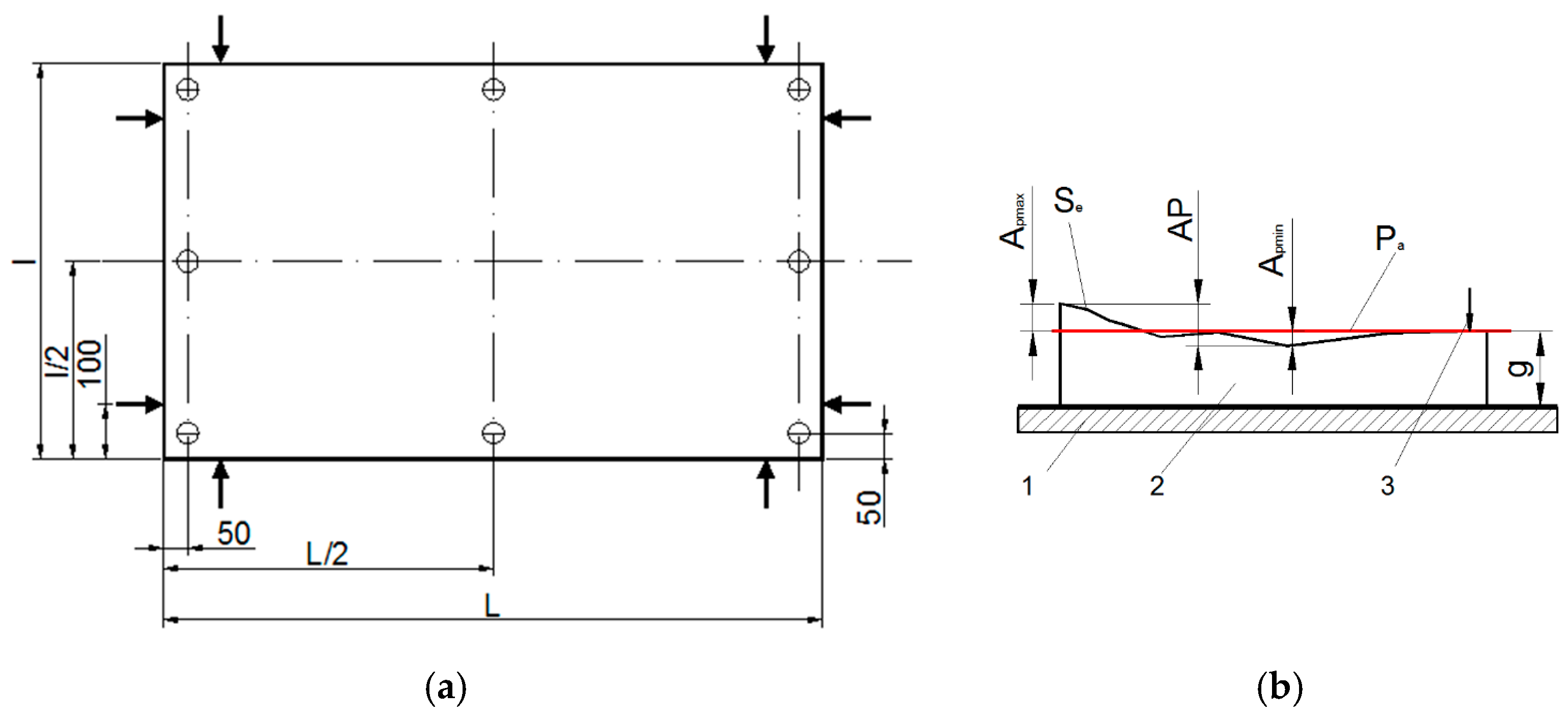
The measurements were carried out with an OPTOdesQ Measurement Table (Hecth Electronic AG, Stuttgart, Germany) equipped with a magnetic measurement system on the three axes, X, Y, and Z, with a precision of 0.01 mm. Both programming and data acquisition were performed electronically by means of the Hecht OptodesQ software package. The size measurement scheme according to EN 324–1: 1993 is shown in Figure 2.
The deviation was calculated as the difference between the actual size and the nominal size, expressed in mm with one decimal for the dimensional deviation and three decimals for the flatness deviation. The mean and standard deviation of the results were determined [29], according to EN 326-1 The calculation of the thickness deviation is based on measuring the thickness at the points set by the user and comparing it with the reference thickness g, the machine directly providing the positive or negative differences from it.
The gluing strength of panel with transverse texture. Bonding strength was determined in accordance with the DD CEN/TS 13354:2003 specifications. The tests were carried out on the Universal Testing Machine type ZDM 5t/510 (PPT Group UK Ltd., West Sussex, United Kingdom). The principle of the method consists of pre-treating the specimens according to the service class established according to EN 1995-1-1, and then in determining the maximum compressive shearing force of the bonding surface. Based on the maximum force and the bonding surface, the gluing strength was determined. The method of specimens cutting from the panel, as well as the shape and dimensions of the specimens, are shown in Figure 3. Sixteen specimens were tested.
Since the panels were designed for small pieces of furniture, used in indoor conditions, the samples, after cutting, were measured and then immersed in cold water (20 °C) for 24 h. After they were taken out of the water, they were measured at the same points as before the immersion.
The determination of the length and width of the shear area was made by using a Holzman digital caliper with a measuring range of 150 mm and a precision of 0.01 mm and a Holzman Rotating Digital Dial Gage (Holzmann maschinen GmbH, Haslach, Austria) with a measuring range of 0–12.5 mm and precision of 0.01 mm. Constant application of shearing force was made at a rate that produces maximum force (break) in approximately 60 ± 30 s. The shear strength of the gluing was calculated with the following relation Equation (1).
f v = F l · g [ N / m m 2 ]
where: fv —the shear strength of the bond, in [N/mm2], F—the maximum force at which the break occurred, in [N], l—the length of the shear area, in [mm], g—the thickness of the specimen, in [mm].
Determination of resistance (MOR) and elasticity modulus (MOE) in static bending. The determination of the modulus of elasticity and the resistance to static bending was carried out according to EN 310:1996. The elastic modulus and static bending strength were calculated using Equation (2).
σ i = 3 · F m a x · l 1 2 · b · t 2    E m = l 1 3 · ( F 2 F 1 ) 4 · b · t 3 · ( a 2 a 1 ) [ N / m m 2 ]
where: σi—the static bending resistance, in [N/mm2], Fmax—the maximum breaking force, in [N], b—width of the specimen, in mm, t—the thickness of the specimen, in [mm], l1—the distance between the supports, equal to 20 times the thickness of the specimen, Em—the modulus of elasticity in static bending, in [N/mm2], (F1F2)—the force increment on the linear portion of force–deformation (F1 = 0.1·Fmax, F2 = 0.4·Fmax), in [N], and (a2a1) represents the increment of the bending arrow corresponding to the force difference (F2F1), in [mm].
The number of specimens according to EN 326-1:1996 was six valid pieces. According to the requirements of EN 310:1996, the specimens had the following dimensions: a thickness equal to that of the panel from which it comes, a width of 50 ± 1 mm, and the length equal to 20 times the thickness plus 50 mm [25,29]. In order to study the influence of the joining method on the strength of the specimen, two types of specimens were cut, namely: specimens with a central longitudinal line of gluing (Figure 4a) and randomly cut specimens (Figure 4b).
The laboratory machine for testing wood-based boards and panel—model IB × 600—produced by IMAL-PAL Group (San Damaso, Italy) was used for the bending test. When the test was finished, the software of the IB × 600 machine calculated both the static bending strength and the modulus of elasticity.
Determination of shear strength parallel to the panel face. The test was determined in accordance with the requirements of EN 13354:2008. The compressive strength parallel to the faces was calculated as the ratio between the maximum force and the breaking surface of the specimen Equation (3). The scheme of the test is presented in Figure 5.
τ f I I = F m a x b · l
where: τfII—the resistance to compression parallel to the faces, in [N/mm2], Fmax—the maximum force, in [N], b—width of sample equal with 50, in mm, l—the breaking length of the specimen equal with 50, in mm2.
Eight specimens were tested [29], in accordance with the requirements of EN 326-1:1996. The dimensions of the sample were: the thickness equal to that of the panel, width of 50 ± 1 mm, and length of 50 ± 1 mm (Figure 5). A Holzman digital caliper with a measuring range of 150 mm and a precision of 0.01 mm was used to determine the thickness of the specimen. A Holzman Rotating Digital Dial Gage (Holzmann maschinen GmbH, Haslach, Austria) with a measuring range of 0–12.5 mm and a precision of 0.01 mm was used to determine the width and length of the sample area. The tests were carried out on the ZDM 5t/51 Universal Testing Machine. To carry out the test in accordance with the requirements of EN 13354:2008, it was necessary to design and make two test devices. In parallel with the samples obtained from panels with a transverse texture of spruce branches, in order to be able to make a comparison, 6 specimens made of veneered chipboard with a thickness of 20 mm were tested for comparison under the same conditions.
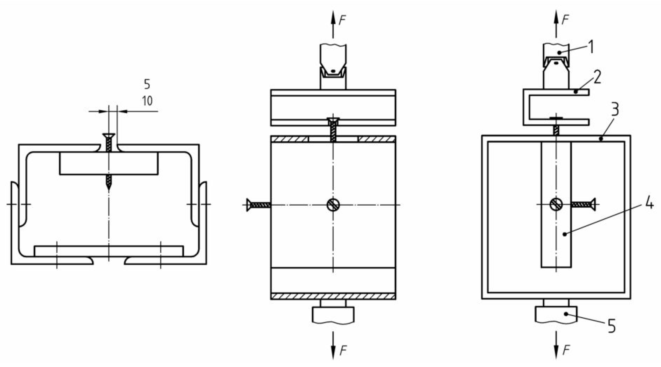
Determination of shear resistance perpendicular to the panel plane. This test was determined in accordance with the requirements of EN 13354:2008. The shear strength parallel to the faces was calculated as the ratio between the maximum force and the breaking surface of the specimen, as in Equation (4). The scheme of determining the shear strength in the plane of the plate is shown in Figure 6.
τ f = F m a x 2 · A
where: τf—shearing resistance to perpendicular plane, in [N/mm2], Fmax—maximum force [N], A—breaking surface of sample, as the product of thickness and 46 mm.
Eight samples were tested in accordance with the requirements of EN 326-1:1996. A Holzman Rotating Digital Dial Gage with a measurement range of 0–12.5 mm and a precision of 0.01 mm was used to determine the thickness of the specimen. To determine the width and length of the specimen, a Holzman digital caliper with a measuring range of 150 mm and a precision of 0.01 mm was used.
Before the test, for each sample, the thickness of the specimens was measured at two points in the direction of the shear planes, and the arithmetic mean of the two measurements was made. The tests were carried out on the ZDM 5t/51 Universal Testing Machine. To carry out the test in accordance with the requirements of EN 13354:2008, it was necessary to design and make the two supports and the force application device.
Determination of the pull-out resistance of screws. This test was determined in accordance with the requirements of EN 13446:2004 (Figure 7). The resistance to pulling out the screws was calculated as the ratio between the maximum force required to pull out the screw and the area of the screwing surface, as in Equation (5).
τ s = F m a x d · l p
where: τs—the resistance to pulling out the screws, in [N/mm2], Fmax—the maximum force required to pull out the screws, in [N], d —the diameter of the screw given by the standard, in [mm], and lp—the screwing length.
Three types of specimens were tested, depending on the structural characteristics of the panel (Figure 8). For each type of specimen, 6 specimens were tested in accordance with the requirements of EN 326-1:1996. The shape and dimensions of the specimens as well as the way of inserting the screws are shown in Figure 8. The screw insertion point can be at the intersection of four joint lines—on a joining line and inside the wood.
The tests were carried out on the FMPW—1000 Traction Machine. For this test, ST 4.2 screws according to ISO 1478 were used, with nominal dimensions of 4.2 × 38 mm and a thread pitch of 1.4 mm [30]. The samples were pre-drilled, the hole diameter being 2.7 ± 1 mm in accordance with EN 320:1993. The penetration depth of the screws is regulated by EN 13446:2004 and for the tested specimens the penetration depth was chosen for the faces—pierced [31,32], and, for the edges, 8 times the diameter, or 21.6 mm.
In the specialized literature, the expression of the resistance to the pulling out of the screws was calculated in accordance with the older norms (EN 13446: 2004), and the expression of the result was communicated in N/mm. In order to be able to compare the experimental data, the calculation of the resistance to the pulling out of the screws was made with Equation (6).
τ s 1 = F m a x h
where: τs1—the pull-out resistance of the screws, in N/mm, Fmax—the maximum force, in N, and h—the penetration depth, in [mm].
Determination of swelling in thickness. The principle of the test consisted in measuring the dimensions before and after immersing them for 24 h in cold water (t = 20 °C) and determining the swelling coefficient with Equation (7).
β = d m a x d m i n d m i n · 100 [ % ]
where: βd—the lineal swelling coefficient, in [%], dmax—the maximum size after immersion, in [mm], and dmin—the minimum size before immersion, in [mm].
To determine the swelling coefficient, the same samples were used for determining the bonding strength. The initial moisture content of the specimens was 9.1% (determined using the gravimeter method EN 322:1993) and the density was 687 kg/m3, determined according to EN 323:1993.
Statistical analysis. All groups of values were processed statistically, obtaining the average of the values, the standard deviation, and the value for a confidence interval of 95% (or the elimination of 5% of the values). This statistical procedure (excluding 5% of the values) was based on a lot of standards and procedures, and has calculated the upper quantile of each group of values according to the arithmetic mean, standard deviation, and Student’s t-distribution with n + 1 degrees of freedom, where n represents the number of attempts of the respective test. The coefficient of variation was also introduced under the name “Variance”, determined with the Microsoft Excel program.

3. Results

3.1. Results Regarding Manufacturing Technology

The specimens from the panels glued with aqueous dispersion polyvinyl acetate (PVC) adhesive after immersion in water became unglued and could no longer be tested [11,12,13]. From this moment, the use of vinyl adhesive was abandoned. The results obtained by applying the polyurethane adhesive were the following: bonding strength of 5.6 N/mm2 before immersion and 4.2 N/mm2 after immersion, compared to 2.5 N/mm2 as the minimum admissible value, a static bending resistance of 5.5 N/mm2, compared to 5 N /mm2 as the minimum admissible value, and the modulus of elasticity of 1027.3 N/mm2, compared to 600 N/mm2 as the minimum admissible value. It is observed that the bonding strength was 124.6% higher than the minimum admissible strength provided by EN 13353:2022, the static bending resistance (MOR) was 11.2% higher than the minimum admissible strength provided by EN 13353:2022, and the value of the bending elasticity modulus (MOE) by 71.2% higher than the minimum admissible figure provided by EN 13353: 2022.

3.2. Results Regarding Dimensional and Flatness Deviations

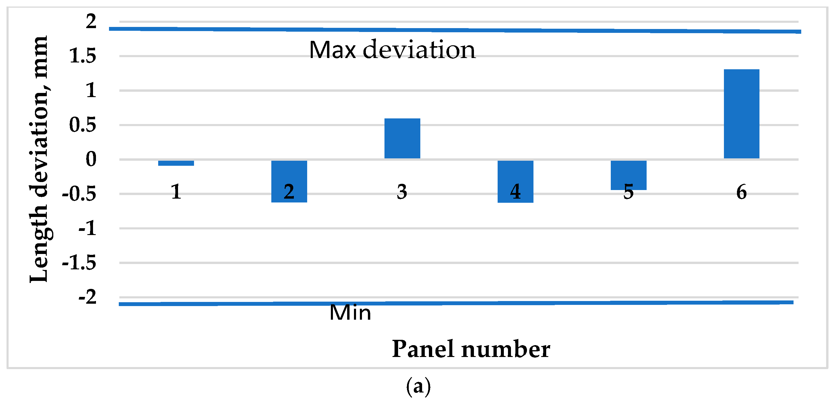
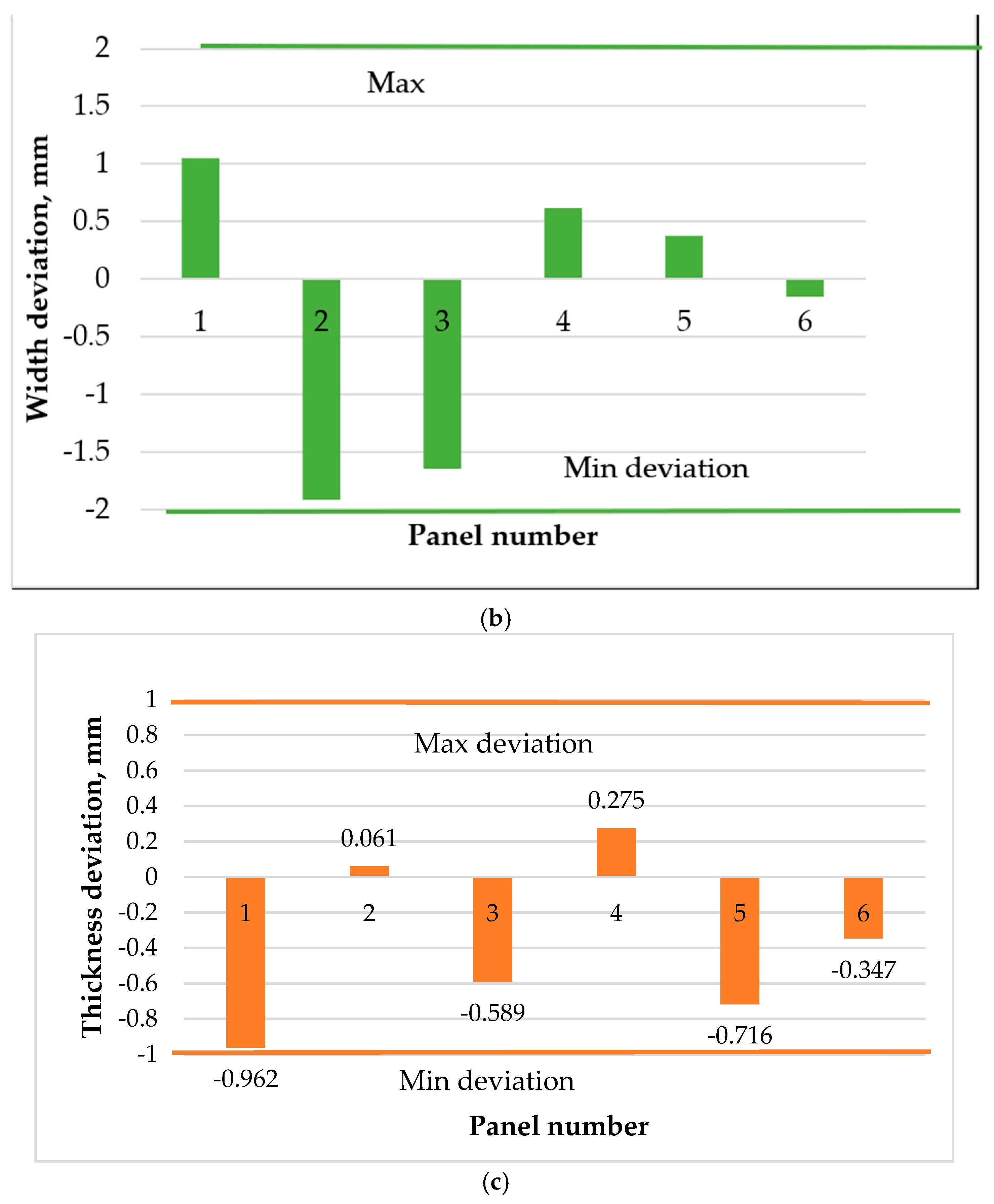
Length, width, and thickness deviations are presented in Figure 9.
In Figure 9, the linear deviations determined according to EN 324-1:1993 and the admissible deviations according to EN 13353: 2022 are compared. According to the data presented, it is found that the dimensional deviations of the panels with a transverse texture made of spruce branches fall within the admissible limits established by EN 324-1. Table 3 shows the deviations from flatness measured with respect to the adjacent plane in the 15 measurement points for each panel.
If both deviations are negative or positive, then the minimum value was taken, and if they are different, their sum was taken. For panels with a length of less than 1000 mm, which are part of the furniture, the admissible deviation from flatness is ±2 mm [12,33], and for boards made of wood chips, the maximum admissible deflection is 1.5–2 mm/m for normally pressed boards and 1.5 mm/m for extruded boards [34]. Eco-panels fit into the requirements stated above (Figure 9, Table 3).

3.3. Bonding Strength Results

The results of the measurements and the interpretation of the results are shown in Table 4.
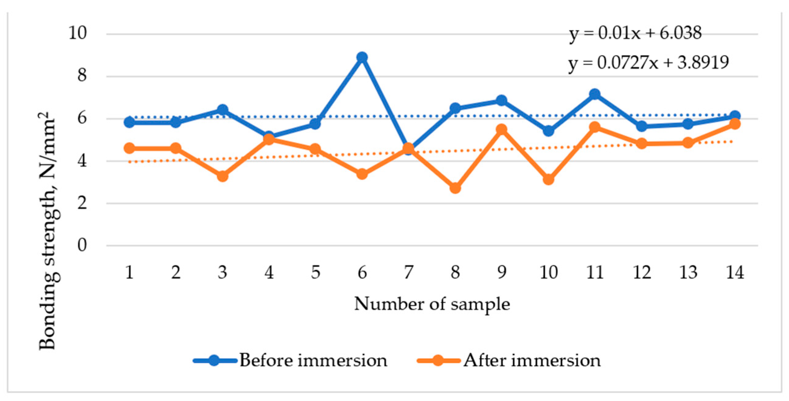
In order to study the influence of moisture content on the gluing resistance, a set of tests was carried out, on a number of 14 specimens, without being previously treated via immersion in cold water; the results of these tests are shown in Figure 10 and are comparative with the water immersion ones.
The gluing resistance of panels with a transverse texture made of spruce branches, determined experimentally according to DD CEN/TS 13354: 2003, falls within the requirements of EN 13353:2022. According to the data from the specialized literature [11,13], the moisture content of the samples almost inversely proportionally influences the bonding strength. In the case of these panels, the gluing resistance after 24-h immersion in cold water (20 °C) was lower by 24.8% than the gluing resistance of the specimens at a 9.1% moisture content. The breakage of the specimens tested at U = 9.1% occurred exclusively in the wood, usually in a different area than the gluing area, and was accompanied by a specific level of noise. For the samples immersed for 24 h in cold water (20 °C), a very high elasticity was observed, and the breaking was performed without noise, usually in the gluing area.

3.4. The Modulus of Elasticity (MOE) and Resistance (MOR) to Static Bending

The results regarding the modulus of elasticity of about 1000 N/mm2 and resistance to static bending of about 6.1 N/mm2 are shown in Table 5. The values determined for both types of specimens (T1—the gluing line in the middle of the test pieces, and T2—the gluing lines are arranged randomly on the face of the samples) fell within the requirements of EN 13353: 2022, which regulate the minimum admissible values of a modulus of elasticity over 600 N/mm2 and resistance to static bending for solid wood panels over 5 N/mm2. A maximum arrow of 7.58 mm was obtained. The samples were broken, producing a characteristic noise of solid wood. The breaking plan was after the tissues of minimum resistance, namely after the medullary rays and separations on the annual ring in the early wood area, meaning that the gluing strength was greater than that of the wood from the branches.
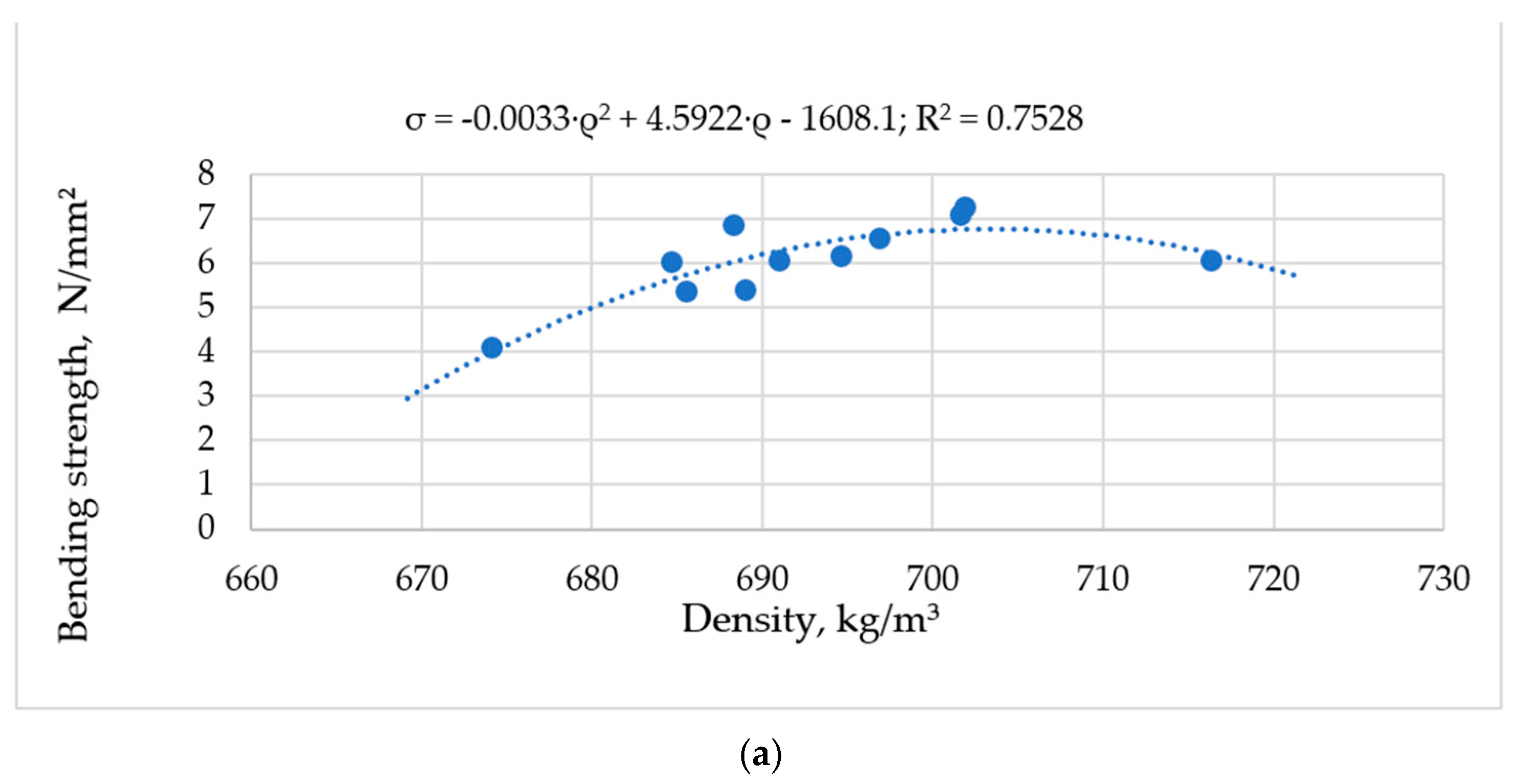
Regarding the influence of density on the static bending resistance (MOR), it could be observed that the resistance to static bending increased with increasing density up to a certain value of 705 kg/m3, then decreases (Figure 11a). The correlation between density and static bending strength is given using a polynomial equation of the second degree, having the density as the parameter and the resistance (MOR) as the dependent variable.
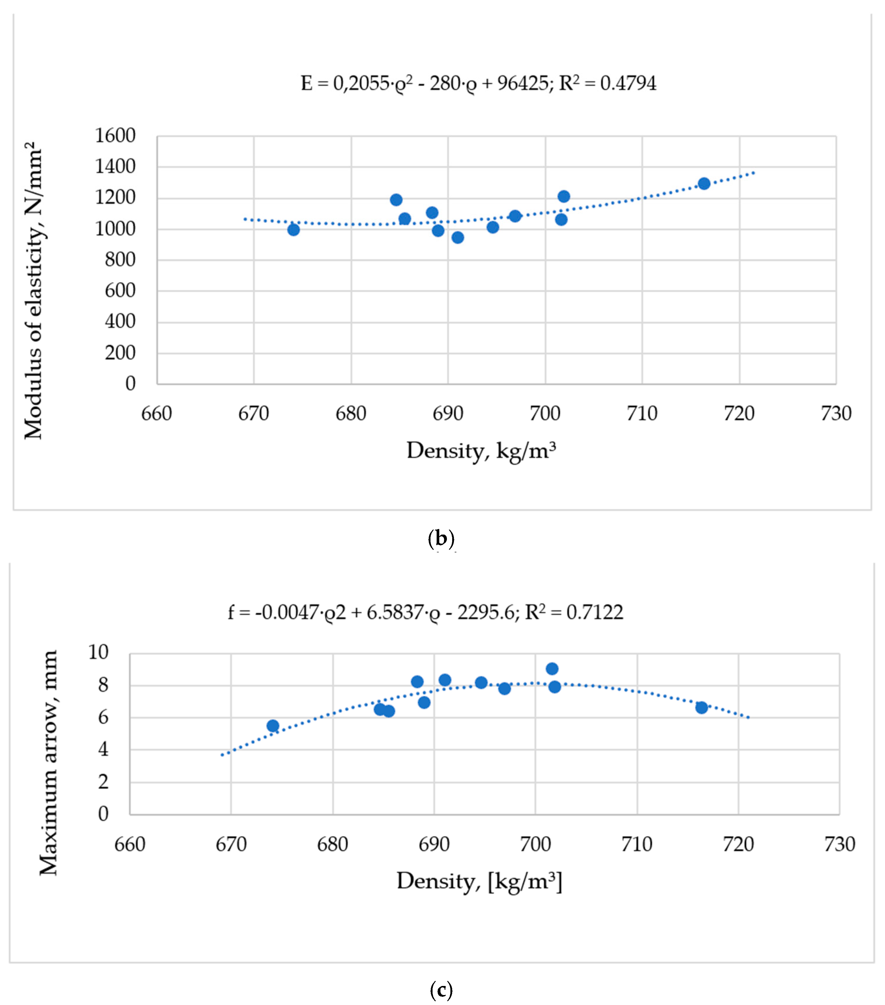
The correlation between density and the modulus of elasticity (MOE) in static bending is given by a second degree polynomial equation with a concave shape (Figure 11b) and with a minimal value of 685 kg/m3. The correlation between density and the maximum deflection in static bending is given by a second degree polynomial equation with a convex shape (Figure 11c) and with a maximal peak of 700 kg/m3.

3.5. Shear Resistance Parallel to the Panel Plane

The results of the tests on shear resistance parallel to the panel plane are shown in Table 6. There were obtained an average resistance of 4.1 N/mm2 and a 46.2 s time of breaking.
Shear strength parallel to the panel plane for other materials; for the 20-mm thick veneered chipboard, it was 1.17 N/mm2, for the 20-mm non-veneered chipboard, it was 1.8 N/mm2, and for the 16-mm thick high-density fiberboard, it was 1.5 N/mm2. These values were inferior to cross-structured panels obtained from spruce branches (3.2 N/mm2). In the case of panels with a cross-section made of spruce branches, shear failure did not occur, as in the case of the chipboard specimens, because the compression with splitting occurred in the upper third of the specimen due to the tangential and normal unit stresses at the surface on the shear plane. The height at which the splitting had occurred varies between 3 and 18 mm, which represents between 6% and 36% of the height of the panel specimen.

3.6. Shear Resistance Perpendicular to the Panel Plane

The results of the tests regarding the shear strength in the plane of the panels are shown in Table 7. There obtained are an average value of resistance of 1.886 N/mm2 and a breaking time of 33.97 s. It can be seen that the breaking time is shorter than in the previous test, due to the fact that the resistance is also lower.
The breakage of the specimens started from the corner of the cuts, advancing in the direction of the medullary rays or in the direction of the annual ring through the early wood zone.

3.7. Results Regarding the Pull-Out Resistance of the Screws

The results obtained after the tests to pull out the screws allowed the formulation of the following conclusions. For screws inserted perpendicular to the plane of the panels, the best resistance to pulling out the screws is given by the situation in which the screw is inserted on a single joint line (type B samples), followed by the situation in which the screw is inserted at the intersection of four joint lines (type A samples), and lastly the situation where the screw was inserted into the wood (type C samples) (Table 8). The pulling out of the screws inserted perpendicular to the plane of the panel was performed silently, with the extraction of the wooden thread formed by the screw, usually without breaking the test piece, and only chips and sawdust in the area of the thread.
For screws inserted parallel to the plane of the panel (on edge), the highest resistance to pulling out the screws is given by the situation where the screw was inserted into the wood but also passes through a joint line (type B samples) followed by the situation where the screw was inserted on four joint lines (type A samples), and lastly the situation where the screw was inserted into the wood (type C samples).
The difference between the pull-out strength of the screws on the different edges was 30.7 N/mm2 for edge 1 and type A, 33.1 N/mm2 for type C, 22.9 N/mm2 for edge 2 type A, and 28.5 N/mm2 for type C. For the identical test cases (specimens of type A and C), it was found that the pull-out resistance of the screws from edge 2 was lower than edge 1 by 25.3% in the case of type A and 13.7% in the case of type C specimens (Table 9). This difference was caused by the weakening of the strength of the test piece during the pulling out of the screw from the edge tested firstly.

3.8. Coefficient of Swelling on the Thickness and Width of the Panels

The swelling coefficient values were tabulated in Table 10.
The value of the swelling coefficient in thickness, i.e., swelling along the fiber, was 1.48%, and the value of the swelling coefficient in width, i.e., tangential swelling, was 2.85%. The coefficients of swelling in thickness after immersion in cold water for 24 h, for the other materials, apart from traverse-structured panels [33,34,35], were limited to 12% for the chipboard, 12% for the medium-density fiberboard (MDF), 15% for the oriented strand board (OSB), 8% for the plywood, 12% for the softwood as spruce, and only 1.4% and 2.8% (on thickness and width) for the traverse-structured panel from spruce branches.
These values obtained experimentally are due to the high content of compression wood (33–66%), and they support the theory from the specialized literature [12,13], according to which compression wood has a high and irregular longitudinal contraction coefficient and a tangential shrinkage coefficient smaller than normal wood. Thus, the ratio of the two types of swelling was, in the case of the panel with the transverse structure of branches, only 1:2, in relation to about 1:20 for the solid wood [35,36].

4. Discussion

Table 11 summarizes the tests to which the cross-textured panels from spruce branches were subjected, the results obtained, the admissible values, the test methodology, as well as the norm that regulates the admissible value. These values are used for comparing them with the results of authors and limitative values of European standards.
All dimensional and flatness deviations fell within the limits provided by the standard [37,38] or expressed by other authors and research in this field. For example, the dimensional deviation in thickness for panel number 2 was 0.061 mm compared to the upper limit of 2 mm according to EN 324-1:1993 and EN 13353:2022, which meant a deviation of the value of 32.7 times.
The apparent density of the panels corresponded to the species used (spruce, with an average wood density of the trunk of 425 kg/m3 and of 510 kg/m3 for the branches [12,36], due to the presence of compression wood), but it also increased significantly due to the Jowapur adhesive used and the pressure force used during the formation of the friezes and panels.
The average value for the resistance of the gluing for the panel made of branches of 5.61 N/mm2 not only corresponded to the limiting value of the European standard (EN 13353: 2022) of 2.5 N/mm2, but also had an increase of 141.3%. Additionally, these values were in accordance with those expressed by other authors [12,13].
The static bending strength of the traverse-structured panel was 10.71% higher than the minimum admissible value recommended by EN 13353:2022, 19.65% higher than the static bending strength of the chipboard with a 20-mm thickness, and 6.6% lower than the static bending strength of the high-density fiberboard (HDF) [33,34]. Regarding the influence of the cutting method of the samples from the panel on the strength and modulus of elasticity in static bending, the followings were observed.
The shear resistance parallel to the board plane was superior to wood-based boards [36], being higher by 56.53–71.65% than the shear resistance parallel to the board plane of the 20-mm thick chipboard, and with 63.77% higher than the shear strength parallel to the plate plane of the high-density fiberboard. The shear resistance perpendicular to the plane of the board was superior to boards based on fibers and wood chips. This was 78.8% higher than the shear resistance perpendicular to the plane of the chipboard with the 20-mm thickness and the same fiberboard [12].
Pulling out the screws inserted parallel to the plane of the panel was performed with noise, without extracting the wooden thread formed by the screw, and usually caused the specimen to break. When screws were inserted perpendicular to the panels, specimen type A had a resistance of 31.7 N/mm2 and a breaking time of 6.3 s, specimen type B had 32.6 N/mm2 resistance and breaking time of 5.4 s, and specimen type C had a resistance of 29.5 N/mm2 and a breaking time of 9.5 s. The strength and pull-out time of the screws for the three cases of screw insertion parallel to the panel plane were for edge 2 and type A, 22.9 N/mm2 and 5.5 s, for type B, 27.3 N/mm2 and 5.4 s, and for type C, 28.5 N/mm2 and 9 s. Screw strength determined according to the old method had different values for all composite materials. The values were 133.1 N/mm for panel type A on the face, 137.2 N/mm for panel type B on the front, and 123.9 N/mm for panel type C on the front, and were comparable with that of 80 N/mm for solid wood with a density of 600 kg/m3, of 100 N/mm for solid wood with a density of 650 kg/m3, and of 150 N/mm for solid wood with a density of 700 kg/m3 [13,36]. By comparing the data obtained with those from the specialized literature regarding the resistance to pulling out screws [35,36], it was concluded that cross-structured panels fall within the requirements imposed by the European norms [35,36].
Values for screw pull-out resistance for various types of materials [33] are: for screws on the plane of the plate (on the edge) with a chipboard density of 600 kg/m3, it was 75 N/mm, for a solid wood density of 500 kg/m3, it was 110 N/mm, and for a solid wood density of 700 kg/m3, it was 170 N/mm, compared to traverse-structured panels that had 280.1 N/mm for panel type A and edge 1, 114.9 N/mm for panel type B and edge 2, and 119.9 N/mm for panel type C and edge 2.
The pull-out force of the screw inserted perpendicular to the panel was quite different compared to the parallel-inserted ones. Comparative to the resistance of a medium-density fiberboard of 1000 N [33], a different force of 2692 N was obtained for panel type A front, 2701 N for the panel type B front, 2439 N for the type C front panel.
Referring to the coefficient of swelling in thickness and width, the fact that at the initial moisture content of 9.1% after immersion in water for 24 h resulted in a swelling coefficient of 1.33%, the theory according to which the wood from the branches has moisture saturation point of the fiber (FSP) approximative 9% [11,12,13] was disproved, despite the fact that the wood in the trunk has a fiber saturation point of around 30%. According to this theory, the panels should not have swelled over 9%, because the swelling and shrinking phenomena occur only in the moisture content range under the fiber saturation point (FSP).
The uses of this type of traverse-structured panel could be various, but it is recommended to use it only in indoor conditions. Even in indoor conditions, the designed panels can be used for small furniture products with dimensions up to 1–1.2 m. These types of panels were used for several types of small furniture, such as tables, coffee tables, desks, etc. (Figure 12).

5. Conclusions

The judicious use of spruce branches in the form of wooden panels leads to obtaining a new base of raw material for the furniture industry.
Highlighting the transverse structure of the spruce wood branches, this technology is considered a method to be taken into consideration by the producers of art furniture.
Even if the technology for obtaining these wooden panels with a transverse texture is not yet patented, this remains a superior valorization solution for the branches, and its viability remains to be demonstrated in the coming years.
Following all tests of research, the panels with a transverse texture from spruce branches could be considered one of the best methods for the high valorization of spruce branches.

Author Contributions

Conceptualization, A.L. and A.M.O.; methodology, A.M.O.; software, L.R.; validation, A.M.O., A.L. and C.S.; formal analysis, A.M.O.; investigation, A.M.O.; resources, A.M.O.; data curation, C.S.; writing—original draft preparation, L.R.; writing—review and editing, A.L.; visualization, A.L.; supervision, A.M.O.; project administration, C.S.; funding acquisition, C.S. All authors have read and agreed to the published version of the manuscript.

Funding

This research received no external funding.

Institutional Review Board Statement

Not applicable.

Informed Consent Statement

Not applicable.

Data Availability Statement

No new data were created.

Acknowledgments

In this way, the authors thank the management of the University of Transilvania Brasov for the logistical and financial support to carry out this research.

Conflicts of Interest

The authors declare no conflict of interest.

References

  1. Hakkila, P. Utilization of residual forest biomass. In Utilization of Residual Forest Biomass; Springer Series in Wood Science; Springer: Berlin/Heidelberg, Germany, 1989. [Google Scholar] [CrossRef]
  2. English, B. Wastes into wood: Composites are a promising new resource. Environ. Health Perspect. 1994, 102, 168–170. [Google Scholar] [CrossRef] [PubMed]
  3. Jahan-Latibari, A.; Roohnia, M. Potential of utilization of the residues from poplar plantation for particleboard production in Iran. J. For. Res. 2010, 21, 503–508. [Google Scholar] [CrossRef]
  4. Tichi, A.H. Investigation of the use of old railroad ties (Fagus orientalis) and citrus branches (orange tree) in the particleboard industry. Bioresources 2021, 16, 6984–6992. [Google Scholar] [CrossRef]
  5. Olarescu, A.M.; Lunguleasa, A.; Radulescu, L. Using deciduous branch wood and conifer spindle wood to manufacture panels with transverse structure. Bioresources 2022, 17, 6445–6463. [Google Scholar] [CrossRef]
  6. Zhao, X.; Guo, P.; Zhang, Z.; Wang, X.; Peng, H.; Wang, M. Wood density and fiber dimensions of root, stem, and branch wood of Populus ussuriensis Kom. Trees. Bioresources 2018, 13, 7026–7036. [Google Scholar] [CrossRef]
  7. Pulido-Rodríguez, E.; López-Camacho, R.; Tórres, J. Traits and trade-offs of wood anatomy between trunks and branches in tropical dry forest species. Trees 2020, 34, 497–505. [Google Scholar] [CrossRef]
  8. Vurdu, H.; Bensend, D.W. Proportions and types of cells in stems, branches, and roots of European black alder (Alnus glutinosa L. Gaertn.). J. Wood Sci. 1980, 13, 36–40. [Google Scholar]
  9. Luan, S.-J.; Yang, R.-P. Predetermination stem wood quality with the branch wood index of Korean pine. J. Northeast For. Univ. 1992, 3, 54–61. [Google Scholar] [CrossRef]
  10. Shmulsky, R.; Jones, P.D. Forest Products and Wood Science: An Introduction, 7th ed.; Wiley-Blackwell Publishing: Hoboken, NY, USA, 2011. [Google Scholar]
  11. USDA Forest Service. Wood Handbook, Wood as an Engineering Material; Forest Products Laboratory. United States Department of Agriculture Forest Service: Madison, WI, USA, 2010.
  12. Petrovici, V.; Popa, V. Chemistry and Chemical Processing of Wood; Lux Libris Print House: Brasov, Romania, 1997. [Google Scholar]
  13. Nielsen, P. Integration of environmental aspects in product development: A stepwise procedure based on quantitative lifecycle assessment. J. Clean. Prod. 2002, 10, 247–257. [Google Scholar] [CrossRef]
  14. Zeng, Y. Environment-Based design (EBD): A methodology for transdisciplinary Design. J. Integr. Des. Process. Sci. 2015, 19, 5–24. [Google Scholar] [CrossRef]
  15. Brezet, H.; van Hemel, C. Ecodesign—A Promising Approach to Sustainable Production and Consumption; United Nations Environment Program: Paris, France, 1997. [Google Scholar]
  16. Bras, B. Incorporating environmental issues in product design and realization. Ind. Environ. 1997, 20, 7–13. [Google Scholar]
  17. Suansa, N.I.; Al-Mefarrej, H.A. Branch wood properties and potential utilization of this variable resource. Bioresources 2020, 15, 479–491. [Google Scholar] [CrossRef]
  18. Moreira, L.d.S.; Andrade, F.W.C.; Balboni, B.M.; Moutinho, V.H.P. Wood from Forest Residues: Technological Properties and Potential Uses of Branches of Three Species from Brazilian Amazon. Sustainability 2022, 14, 11176. [Google Scholar] [CrossRef]
  19. Zayed, M.Z.; Wu, A.; Sallam, S. Comparative phytochemical constituents of Leucaena leucocephala (Lam.) leaves, fruits, stem barks, and wood branches grown in Egypt using GC-MS method coupled with multivariate statistical approaches. Bioresources 2019, 14, 996–1013. [Google Scholar] [CrossRef]
  20. EN 13353:2022; Solid Wood Panels (SWP). Requirements. European Committee for Standardization: Brussels, Belgium, 2022.
  21. DD CEN/TS 13354:2003; Solid Wood Panels—Bonding Quality—Test Method. European Committee for Standardization: Brussels, Belgium, 2003.
  22. EN 1995-1-1:2004+A 1; Eurocode 5: Design of Timber Structures—Part 1-1: General—Common Rules and Rules for Buildings. European Committee for Standardization: Brussels, Belgium, 2004.
  23. EN 335-2:2006; Durability of Wood and Wood-Based Products—Definition of Use Classes—Part 2: Application to Solid Wood. European Committee for Standardization: Brussels, Belgium, 2006.
  24. EN 310:1996; Wood Based Panels—Determination of Modulus of Elasticity in Bending and of Bending Strength. European Committee for Standardization: Brussels, Belgium, 1996.
  25. EN 324-1:1996; Wood Based Panels—Determination of Dimensions of Boards—Part 1: Determination of Thickness, Width and Length. European Committee for Standardization: Brussels, Belgium, 1996.
  26. Mantanis, G.I.; Young, R.A.; Rowell, R.M. Swelling of wood. Wood Sci. Technol. 1994, 28, 119–134. [Google Scholar] [CrossRef]
  27. EN 13354:2008; Wood Based Panels—Small Scale Indicative Test Methods for Certain Mechanical Properties. European Committee for Standardization: Brussels, Belgium, 2008.
  28. EN 326-1:1996; Wood Based Panels—Sampling, Cutting and Inspection—Part 1: Sampling and Cutting of Test Pieces an Expression of Test Results. European Committee for Standardization: Brussels, Belgium, 1996.
  29. ISO 1478:1999; Tapping Screws Thread. International Organization for Standardization: Geneva, Switzerland, 1999.
  30. EN 322:1993; Wood-Based Panels. Determination of Moisture Content. European Committee for Standardization: Brussels, Belgium, 1993.
  31. EN 13446:2004; Wood Based Panels—Determination of Withdrawal Capacity of Fasteners. European Committee for Standardization: Brussels, Belgium, 2004.
  32. Barbu, M.C. Wooden Composite Materials; Lux Libris Print House: Brasov, Romania, 1999. [Google Scholar]
  33. Istrate, V. Technology of Wooden Agglomerated Products; Didactical and Pedagogical Print-House: Brasov, Romania, 1983. [Google Scholar]
  34. Giese-Hinz, J.; Jahn, F.; Weller, B. Experimental study of the pull-out resistance of alternative high-strength fasteners for wood-based materials. Wood Mater. Sci. Eng. 2018, 14, 226–233. [Google Scholar] [CrossRef]
  35. Wood Database 2023. Available online: https://www.wood-database.com/?s=white+spruce (accessed on 5 July 2022).
  36. Salem, M.Z.M.; Zayed, M.Z.; Ali, H.M.; El-Kareem, M.S.M.A. Chemical composition, antioxidant and antibacterial activities of extracts from Schinus molle wood branch growing. Egypt. J. Wood Sci. 2016, 62, 548–561. [Google Scholar] [CrossRef] [Green Version]
  37. EN 325:2012; Wood-Based Panels—Determination of Dimensions of Test Pieces. European Committee for Standardization: Brussels, Belgium, 2012.
  38. EN 323:1993; Wood-Based Panels—Determination of Density. European Committee for Standardization: Brussels, Belgium, 1993.
Figure 1. The manufacturing technological flow of panels with a transverse texture of spruce branches (a), and a panel with a transverse texture of spruce branches (b).
Forests 14 00665 g001aForests 14 00665 g001b
Figure 2. Scheme for measuring panel dimensions according to EN 324-1:1993 (a), and measurement of flatness deviation with OPTOdesQ Measurement Table. (b): 1—mass of the machine; 2—the measured panel; 3—feeler rod; g—reference thickness; Pa—the adjacent plane; Se—the effective surface; Apmin—minimum (negative) deviation from flatness; Apmax—maximum (positive) deviation from flatness.
Forests 14 00665 g002
Figure 3. Specimen sizes for determining the gluing strength (a), and position of specimen in time of breaking (b).
Forests 14 00665 g003
Figure 4. Specimens with a central longitudinal bonding line (a), and randomly cut specimens (b).
Forests 14 00665 g004
Figure 5. Scheme for determining the shearing resistance in the plane of the plate: (a)—outline of the test; F—force of shearing; hd—shearing height; (b)—breaking the samples; (c)—dimensions of the samples. Scheme for determining the shearing resistance in the plane of the plate: F—force of shearing; hd—shearing height.
Forests 14 00665 g005
Figure 6. Principle scheme of determining the shear strength in the plane of the panel (a), and the dimensions of the sample. (b): 1—sample; 2,3—supports; 4—the force application device.
Forests 14 00665 g006
Figure 7. The scheme for determining the resistance to screw pull-out.
Forests 14 00665 g007
Figure 8. The shape and dimensions of the tested specimens: (a)—the screw insertion was made at the intersection of four gluing lines; (b)—the screw was inserted on a gluing line; (c)—the screw insertion was made in wood.
Forests 14 00665 g008
Figure 9. Deviation on panel length (a), width (b), and thickness (c).
Forests 14 00665 g009aForests 14 00665 g009b
Figure 10. Bonding strength of cross-textured panels made of spruce branches.
Forests 14 00665 g010
Figure 11. The relationship between density and static bending strength (a), density and modulus of elasticity (b), and density and maximum arrow (c) for panels made of spruce branches.
Forests 14 00665 g011aForests 14 00665 g011b
Figure 12. Examples of using traverse structured panels made of spruce branches.
Forests 14 00665 g012
Table 1. Type and duration of the prior treatment depending on the environment of use.
TypeConditions of Use Conform EN 13353: 2022Type of Prior Treatment
T1SWP/1 Dry medium (interior)Immersion in water (20 °C, 24 h)
T2SWP/2 Wet medium Boiling, 6 h
Cooling in water (20 °C, 1 h)
T3SWP/3 Exterior mediumBoiling, 4 h
Drying in oven (60 °C, 16–20 h)
Boiling, 4 h
Cooling in water (20 °C, 1 h)
Table 2. Physical and mechanical tests to which the panels from the branches were subjected.
No.Name of the Mechanical TestJustification of the ChoiceNormNumber of Specimens
1. Dimensions of the panelsIt reflects the dimensional accuracy of panel manufacturingEN 324-1:1993 6
2. FlatnessThe basic technological property of panelsMantanis et al., 1994 [27]6
3. Bonding strengthThe basic property of any glued product. It influences most of the mechanical propertiesEN 13354:2008 minim 10
4. Modulus of elasticity and resistance to static bendingImportant for horizontal elements in furniture construction (boards, shelves, etc.)EN 310:19966
EN 326-1:1996
5.Shear resistance in the plane of the plateImportant for vertical or horizontal elements subject to shear (side walls, uprights, crossbars, etc.)EN 13354:2008 8
EN 326-1:1996
6. Shear resistance perpendicular to the face plate
7. The pull-out resistance of the screwsScrew assemblies are frequently used in furniture constructionEN 13446:2004 6
8. Determination of the swelling coefficientIt determines the stability of structures in various environmental conditions Mantanis et al., 1994 14
Table 3. Deviation (D) from flatness of panels with transverse texture obtained from branches.
No.Panel Number
Panel P1Panel P2Panel P3Panel P4Panel P5Panel P6
Dmax mm−0.20.230.050.16−0.050.14
Dmin mm−1.19−0.09−0.67−0.51−0.61−0.51
Dmean mm1.190.320.720.670.610.65
Variance0.0630.0310.0510.0470.0450.046
Table 4. The gluing resistance of panels.
No.Dimension MC = 9.1%Dimensions after Immersion in WaterMaxim Force [N]Bonding Strength
[N/mm2]
Time [s]
g [mm]l [mm]g [mm]l [mm]
Mean19.74625.02320.04025.73824034.8846.7
SD0.0890.1200.1040.2591201.402.33
Except 5%19.70724.97019.99525.62423604.2245.1
Variance0.00450.00470.00510.01010.04990.02860.0498
Admissible Minim 2.5 N/mm2 EN 13353 2022
Table 5. Results of bending strength (MOR, MOE, and maximum arrow).
No.Density [kg/m3]MOR [N/mm2]MOE [N/mm2]Maximum Arrow [mm]
T1T2T1T2T1T2T1T2
Mean693.2692.36.096.101129.9710067.157.58
SD [%]14.163.11.120.41102.5844.171.240.59
Except 5%682.8657.75.275.791054.68956.16.247.20
Variance0.0200.0040.0180.0670.0900.0430.0230.077
Table 6. Shear resistance parallel to panel face (SD—standard deviation).
No.Length, [mm]Width, [mm]Force, [N]Shear Resistance Parallel to Face,
[N/mm2]
Time,
[s]
Mean50.44350.42610541.254.14146.212
SD0.2570.2932036.040.78116.472
Table 7. Perpendicular-to-plate shear strength of cross-textured panels (SD—standard deviation).
No.Thickness 1 [mm]Thickness 2 [mm]Mean ThicknessMaximum Force
[N]
Shearing Resistance [N/mm2]Breaking Time,
[s]
Mean19.78819.78219.78522401.88633.97
SD0.0490.0510.046488.60.4112.374
Variance0.0020.0020.00230.02170.02120.067
Table 8. Screw pull-out resistance parallel to the face panels (SD—standard deviation).
Sample Type No.Screw Pull-Out, Parallel to the Panel Face
lp,
[mm]
d
[mm]
Force,
[N]
Time,
[s]
τs
[N/mm2]
τs1 [N/mm]
Type AMean19.7074.226246.30831.704133.158
SD 0.071347.40.9324.18917.596
Type BMean19.67527015.4332.684137.275
SD0.0302261.11.4453.16813.306
Type CMean19.67524399.59529.520123.984
SD0.030617.43.0667.48631.444
TotalMean19.68525887.11131.303131.473
SD0.047424.82.6535.14321.601
Table 9. The pulling out resistance of the screws on the edge of panel (SD—standard deviation).
Sample TypeNo.Edge 1 Edge 2
τs [N/mm2]τs1 [N/mm]F [N]t [s]τs [N/mm2]τs1 [N/mm]
Type BMean27.111113.88824825.44227.358114.907
SD14.94262.758474.4624.0110.33543.410
Type CMean33.090115.817962.0019.22328.549119.907
SD5.98925.154474.4620.9924.13417.365
TotalMean30.327119.6551843.3337.33226.300105.001
SD9.92646.306665.0013.0727.33030.218
Table 10. The swelling coefficient after immersion (SD—standard deviation).
No.Dimension MC = 9.1%Dimension after Immersion in Water Swelling Coefficient on Thickness, [%]Swelling Coefficient on Width, [%]
g, [mm]l, [mm]g, [mm]l, [mm]
Mean19.7425.02320.0425.7381.4872.858
SD [%]0.0890.120.1040.2590.3511.028
Except 5%19.70724.9719.99525.6241.3342.407
Variance0.00450.00480.00520.00970.02370.0357
Table 11. Synthesis of the physical–mechanical and technological properties of panels with a transverse texture obtained from spruce branches (SD—standard deviation).
No.CharacteristicsMethodology According to which the Test was Carried OutValueSDUM
1.Deviation from nominal lengthEN 324-1:1993; EN 324-2:1993; EN 13353:2022Mean0.030.001mm
Admissible±2-
2.Deviation from the nominal widthEN 324-1:1993; EN 324-2:1993; EN 13353:2022Mean−0.62−0.003mm
Admissible±2-
3.Deviation from the nominal thicknessEN 324-1:1993; EN 324-2:1993; EN 13353:2022Mean0.470.023mm
Admissible±1-
4.Deviation from flatness[27]Mean1.3040.065mm
Admissible2-
5.Apparent density at MC = 9.1%EN 323:1993Mean687.0514.1kg/m3
Admissible--
6.Internal bond resistance at MC = 9.1%EN 13354:2008Mean5.610.25N/mm2
Admissible2.5-
7.Bonding strength after 24-h immersionEN 13354:2008; EN 13353:2022Mean4.220.21N/mm2
Admissible2.5
8.Modulus of elasticity (MOE)EN 310:1996; EN 13353:2022Mean1027.38102.5N/mm2
Admissible600-
9.Static bending resistance (MOR)EN 310:1996
EN 13353:2022
Mean5.571.12N/mm2
Admissible5-
10.Shear resistance parallel to the panel planeEN 13354:2008Mean4.140.78N/mm2
Admissible--
11.Shear resistance perpendicularEN 13354:2008Mean1.880.41N/mm2
Admissible--
12.Pull-out resistance of screws perpendicularEN 13446:2004Mean31.305.14
Admissible--N/mm2
13.Pull-out strength of screws parallelEN 13446:2004Mean30.829.9N/mm2
Admissible--
14.Coefficient of swelling in thickness[12,36]Mean1.330.35%
Admissible--
15.Coefficient of swelling in width[12,36]Mean2.401.00%
Admissible--
Disclaimer/Publisher’s Note: The statements, opinions and data contained in all publications are solely those of the individual author(s) and contributor(s) and not of MDPI and/or the editor(s). MDPI and/or the editor(s) disclaim responsibility for any injury to people or property resulting from any ideas, methods, instructions or products referred to in the content.