1. Introduction
Every year, the global energy demand is growing faster and it is expected to double by 2050 [
1,
2]. The primary world energy demand in 2018 represented 13.9 Gtoe (gigatons of oil equivalent), of which about 89% were fossil fuels [
3]. In the European Union, fossil fuels and other non-renewables stood for 86% of the energy demand in the same year [
4]. These data, together with the presented predictions and the global warming problem, stress the urgency to focus on energy production from renewable sources, environmentally friendly technologies and technologies with higher energy efficiency.
The increasing trend of using biomass as a source of energy and materials brings opportunities to the pulp industry as it is a large source of biomass in the form of black liquor and wood residues [
5]. This material is traditionally combusted in recovery boilers; however, black liquor gasification is studied and developed as a modern way of waste utilization [
6,
7,
8,
9]. Gasification is a widely discussed and studied process of waste and biomass processing to increase the energy efficiency of processes and to lower the environmental impact of waste treatment [
10,
11]. Many studies on the black liquor gasification process have been performed and some pilot plants have been installed and operated [
7,
12,
13,
14]. The produced gas contains a significant portion of sulfur compounds [
5,
7,
15]. Most modeling and computational studies simply assumed sulfur removal by a non-specified method and did not solve the related problem of returning this sulfur back to the process in white liquor [
5,
16,
17].
A high sulfur content in biomass from pulp mills results from the pulping process where white liquor (WL) (mixture of sodium hydroxide and sodium sulfide and other chemicals) is used for chemical pulping [
18]. These chemicals, together with lignin and other wood components or impurities, are then separated from the pulp in washing units and concentrated in a series of evaporators to around 80–85% wt. This concentrated solution is called strong black liquor and it is traditionally combusted in recovery boilers. In this process, sulfur compounds exit the recovery boiler in the form of smelt that is converted back into white liquor. In the gasification process, however, a significant amount of sulfur is converted into hydrogen sulfide which then exits the gasifier together with the produced gas. Sodium sulfide and sodium hydroxide represent active components of white liquor in the pulping process and the Na
2S deficit has to be compensated by sodium hydroxide purchase, leading to operational costs increase.
Thus, the effort to remove sulfur from the produced syngas from black liquor is driven by two simultaneous needs: 1. to clean the syngas sufficiently before its further use as fuel in a gas turbine or as feed for the production of chemicals; 2. to recycle the separated sulfur stream back to the pulping process in a suitable form (active cooking chemical). While in industrial practice the first operation is traditionally encountered in refining, petrochemistry, steelmaking or in biogas cleaning facilities, analysis of the energy intensity and material efficiency of the second one has been far less studied and relevant scientific studies focusing on this aspect particularly are missing. As to overcome this scientific research and discussion absence and to convey relevant findings to the scientific and industrial community, the presented work focuses on the integration of both sulfur cleaning and recovery in one step. The goal of the study is to answer the following questions:
What equipment is needed for efficient sulfur recovery and recycling in the pulping process? Does it impact other production units involved in the pulping process in any way?
What are the associated investment and operational costs?
To what extent does sulfur recovery impact the economic feasibility of black liquor gasification in general?
For analysis and comparison purposes, two possible absorbents were chosen and used in the Aspen Plus simulation software for syngas cleaning and sulfur recycling in the cooking process. Using the simulation results, investment and operating costs were estimated by Aspen Plus Economics as the main source of information, together with data from various literature sources for price comparison.
Key findings from the presented analysis highlight its scientific contribution to a better understanding and assessment of technologic and energetic issues resulting from black liquor gasification:
A significant amount of carbon dioxide present in the produced syngas can be absorbed along with hydrogen sulfide and is recycled back to the pulping process with tremendous impact on the lime kiln load to counterbalance the cooking liquor causticity reduction.
Weak N-methyldiethanolamine (MDEA) aqueous solution should be used preferentially as the H2S absorbent due to its better selectivity compared to the direct syngas cleaning by absorption in white liquor or in a sodium hydroxide solution.
A complex system, comprising absorption, desorption and re-absorption columns, is needed to efficiently recycle sulfur back to the pulping process.
Estimated operational costs resulting from gas cleaning and sulfur recovery and recycling drastically reduce the economic feasibility of black liquor gasification in general.
Paper organization is as follows:
Section 2 introduces a model black liquor gasification process followed by comparison of syngas cleaning options.
Section 3 presents the process model in Aspen Plus, the considered gas cleaning alternatives and the approach chosen for the process economic evaluation.
Section 4 shows the obtained results along with the related discussion, while the Conclusions section sums up the key findings.
2. Gasification Process
The gasification process includes several necessary operations to produce clean gas that can be used for combined heat and power or specialty chemicals production [
6,
7,
19]. During the gasification process, organic compounds in the biomass are converted into a gas containing mostly CH
4, H
2, CO and CO
2. Depending on the biomass type and source of the oxidizing agent, gas can contain also sulfur compounds such as H
2S and nitrogen compounds such as NH
3 [
8,
15,
20]. Two main types of gasification exist: low-temperature and high-temperature gasification. Low-temperature gasification is operated at temperatures below the melting point of inorganic salts in black liquor (600–850 °C) and high-temperature gasification is operated at temperatures above this point (900–1000 °C) [
6]. Melting points of inorganic salts that can be present in black liquor are listed in
Table 1. As the oxidizing agent in the gasification process, pure oxygen, air or steam can be used [
12].
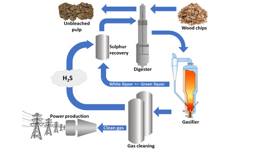
A simplified schematic description of the gasification process with gas cleaning and processing is shown in
Figure 1. Produced smelt exits the gasifier at the bottom and is further processed to white liquor. Gas is first cooled down in a series of heat exchangers where steam is produced. As the synthesis gas contains a significant amount of sulfur compounds (H
2S), it has to be cleaned, which is mostly performed by amine absorption. Clean gas can be further utilized for combined heat and power production or poly-generation (heat, power and chemicals or biofuels production). A more detailed description of this process is presented in following
Section 2.1 and
Section 2.2.
One of the main problems of gasification modeling is tar production. When considering tar production, it would be needed to simulate tar separation in a separate unit, together with possible tar condensing and capturing in heat exchangers. In many works focused on gasification modeling, the most common approximation/simplification does not consider tar production. This approximation can be made in this paper as well, as the investment and operational costs of a tar separation unit would be the same for both gas cleaning variants.
2.1. Model Gasification System
In this paper, gasification and gas cleaning processes modeling was attempted considering high-temperature black liquor gasification at 3 MPa and 800 °C with pure oxygen as the oxidizing agent [
21,
22]. The amount of black liquor was set to 1600 tons per day of dry solids (tpd DS), which represent 85% wt. of black liquor. The temperature of black liquor and oxygen at the input of the gasifier was set to 120 °C. The calculated amount of oxygen needed for the gasification is 28,068 kg/h. The overall material balance of the gasification process is shown in
Appendix A Table A1. Other black liquor parameters are summed up in
Table 2. When modeling the gasification system, several assumptions were made: the reactor was modeled as a Chemrec gasifier (gasifier model in Aspen Plus simulation software) with a reactor part, where gasification takes place, and a quenching part, where syngas from the reactor is quenched by a so-called weak wash (condensates from syngas cooling in further heat exchangers) and cooled down to a temperature of about 200 °C; production of tar was not considered in the simulation as tar separation would have the same economic impact on both studied gas cleaning processes; and green liquor composition and sulfur distribution in green liquor were set based on the composition of green liquor produced from black liquor combustion. A large-scale pulp mill with such black liquor production typically needs around 2400 tpd of white liquor for the chemical pulping process, which is produced in the causticizing unit of the chemical recovery cycle. This part of the recovery cycle is better described in
Section 3.1.
Simulation of the gasification process was performed using the Aspen Plus simulation software (Aspen Plus V10, Aspen Technology Inc., Bedford, MA, USA). As the gasification is a complex process which cannot be modeled as a single piece of equipment, it had to be treated in Aspen Plus as a series of units and operations [
8,
15,
23]. A scheme of the black liquor gasification process modeled in Aspen Plus is shown in
Figure 2. First, feed (black liquor) had to be broken into elements in BREAK units, entering then, together with oxygen, the gasification reactor (GASIF). Products of gasification were then quenched in Q1 and Q2. However, as a reaction occurs during this process, another reactor (QUENCH) had to be implemented. Its input was half of the gas product from Q1 (as not all the gas reacts in the quenching part due to the low residence time). This assumption was made to achieve the same results as models in the literature [
8]. The gas was quenched by condensates from syngas cooling in the next steps. During the cooling process, low-pressure and very low-pressure steam were produced in heat exchangers.
The obtained composition of dry syngas is shown in
Table 3. The lower heating value of syngas was calculated as the sum of heating values of pure components in MJ/Nm
3 (H
2—10.8; CO—12.63; CH
4—35.85; H
2S—21.8) multiplied by their volume ratios in syngas. A list of equipment and material streams from
Figure 2 is provided in
Table 4 and
Table 5. Detailed gasifier operation data are provided in
Appendix A,
Table A1.
For modeling purposes, the Gibbs reactor model was used together with the equilibrium temperature set to 2017 °C, in order to obtain results similar to literature data mentioned before. The approach temperature is commonly used in this case in such a simulation setup. The thermodynamic model used for gasification modeling was the Peng–Robinson equation of state with Boston–Mathias modification for physical properties estimation of conventional components. This model is commonly used for gasification modeling in Aspen Plus [
24,
25].
2.2. Gas Cleaning
Produced syngas contains up to 1.4% vol. of hydrogen sulfide due to the high sulfur content in black liquor, which has to be separated to use syngas for chemicals production or combined heat and power production, where the optimal content of H
2S in fuel entering the gas turbine is about 20 ppmv [
27,
28,
29]. Further, the sulfur dioxide content in flue gas is limited to about 15 mg SO
2/Nm
3 with 15% excess of oxygen at the standard condition [
30]. No compressor needs to be installed as the gas flows freely through the equipment along the pressure gradient. Several processes used for sulfur compounds separation from a gas stream can be employed; however, another problem in the separation process is the high amount of carbon dioxide present in syngas and its good absorption ability.
Table 6 shows a brief guideline for the selection of H
2S and CO
2 removal processes. The dividing line between low (L) and high (H) represents 20 MMscfd (22,318 Nm
3/h) for plant size, 100 psia (689 kPa) for partial pressure and 10 tons/day for sulfur capacity [
31].
One of the most common ways of cleaning acid gases is absorption with two different types of absorption: physical and chemical absorption. The most common absorbents used for acid gas absorption are sodium hydroxide and amines, such as diethanolamine (DEA), N-methyl diethanolamine (MDEA) or ethanolamine (ETA or MEA) [
31,
32]. In pulp and paper mills, white liquor can be used as a source of sodium hydroxide [
33]. Other absorbents that can be used in syngas cleaning are so-called Selexol (mixture of dimethyl ethers and polyethylene glycol) and Rectisol (cold methanol at −40 °C) [
34], which are supposed to remove almost all H
2S and CO
2 from the inlet gas in separated streams [
31,
34]. Another option of gas cleaning is adsorption with zinc oxide or iron oxides used for low-temperature adsorption [
35]. When using low-cost adsorbents such as dolomite, limestone or CaO, the temperature of the inlet gas has to exceed 600 °C, mostly in the range of 900–1000 °C [
36,
37], which is not feasible for the gasification process where the syngas exiting the gasifier has a temperature of around 200 °C. The temperature of syngas exiting the gasifier, however, varies based on the type of gasifier. In some cases, for example, avoiding syngas quenching right after the gasification section, the syngas temperature at the output of the gasifier can be up to 900 °C, and using low-cost adsorbents is more suitable.
3. Modeling of Syngas Cleaning and Sulfur Recovery
In the model of gas cleaning, two absorbents were chosen—white liquor together with sodium hydroxide solution and MDEA solution. In the syngas cleaning modeling in Aspen Plus or HYSYS simulation softwares, the Aspen Plus simulation software was preferred as it can estimate the Murphree efficiency for H
2S and CO
2 absorption correctly [
38].
For modeling in Aspen Plus, three common thermodynamic models to include electrolytes in the solution (ELECNRTL, ENRTL-RK and ENRTL-SR) can be applied [
39,
40,
41]. The ELECNRTL model is more versatile as it can handle all kinds of solvent systems as well as very low and very high concentrations. ENRTL-RK and ENRTL-SR modes represent an improved ELECNRTL method for better prediction of vapor phase properties [
39,
40]. The ENRTL-RK thermodynamic model is also widely used in models with aqueous solutions, like in our case with white liquor, NaOH solution or MDEA solution. Therefore, for the purpose of this work, the ENRTL-RK thermodynamic model with an equilibrium-based approach was used as such a model is best suited for the analyzed system.
For syngas purification equipment modeling, the RadFrac calculation model in Aspen Plus was used. Equilibrium calculation coupled with Murphree efficiency [
38] was adopted.
3.1. Absorption in Alkaline Solution
Syngas cleaning using alkaline solution employs two absorption columns, as shown in
Figure 3. In the first column, white liquor was used as the absorbent and in the second one, sodium hydroxide solution was used, as the use of white liquor solely did not suffice to clean syngas to the set purity of 20 ppm. To lower the amount of used fresh sodium hydroxide solution in the second absorption column, recycling of the outlet stream was implemented. Temperatures of syngas and white liquor at the entrance to the first absorption column were both set to 100 °C and that of sodium hydroxide entering the second column was set to the same value as that of syngas exiting the first column. The temperatures were thus set to avoid lower cleaning efficiency at lower temperatures resulting from sensitivity analysis (
Figure 4). The share of individual inorganic compounds in white liquor used in the simulation is shown in
Table 7. Detailed operation data of the white liquor column and of the NaOH column are provided in
Appendix A,
Table A2 and
Table A3, respectively.
Equations (1)–(4) represent reactions considered in the absorption columns [
39].
As the spent white liquor and sodium hydroxide solution contain high amounts of sodium carbonate and a very low to almost zero amount of unreacted sodium hydroxide, sodium hydroxide has to be recovered in the so-called causticization process, where the reaction in Equation (5) takes place [
33]:
Produced lime mud (CaCO
3) is calcined in a rotary lime kiln at the temperature of around 850 °C (Equation (6)).
High temperature in the lime kiln is achieved by combustion of natural gas. Material and energy balance of the lime kiln were calculated in Excel to evaluate the economic aspect of this process. Around 5.8 GJ of fuel energy is needed to produce 1 ton of CaO in the lime kiln [
43].
3.2. Absorption in MDEA Solution
As an alternative to white liquor and sodium hydroxide solution, amine solution can be used. Equations (7)–(11) represent reactions occurring in the absorption of hydrogen sulfide and carbon dioxide in MDEA [
30]:
A 10% wt. MDEA solution was used, whose concentration is supposed to be the best for co-absorption of the lowest amount of CO
2 from syngas according to the literature [
44], and this was later confirmed by our calculations. The temperature of both syngas and lean amine entering the column was set to 40 °C. Pressure in the desorption column was set to 2 bar. Off-gas, containing H
2S and CO
2 absorbed in absorption column from the syngas, can be dissolved in white liquor on its way to the calcination unit. The amine absorption process is more complex than the described absorption in alkaline solution which can be also seen in
Figure 5. Detailed operation data of the MDEA absorption column are provided in
Appendix A,
Table A4.
3.3. Economic Analysis
For the economic analysis and equipment price calculation, Aspen Plus Economics was used, however, some of the equipment like the gasifier must be evaluated using literature data. Equipment costs from Aspen Plus are compared to those evaluated by the exponential method based on existing cost data of the same equipment with different capacity. An indexation method using the Marshall and Swift (M&S) or the Chemical Engineering Plant Cost Index (CEPCI) indices [
45,
46] and the exponential method for equipment of different capacity were also used in the economic analysis. Equations (12) and (13) represent the indexation and exponential methods for cost estimation:
where
Cpresent and
CIpresent are the cost of the equipment and the cost index (CEPCI or M&S) in the present,
Cpast and
CIpast are the known cost of the equipment in the past and the cost index for the same year, respectively, and
C1 and
C2 represent the cost of equipment with capacity
q1 and
q2, respectively. The scaling factor,
n, typically ranges between 0.5 and 0.7 depending on the equipment, with an average in the chemical industry of 0.6 [
45].
Direct and indirect capital costs employed in the economic evaluation were estimated using the so-called Baumann multiple-factor method (Equation (14)).
where
CFC represents fixed capital cost,
Ceq represents equipment cost and
fi represents Baumann factors for direct or indirect capital cost estimation (
Table 8).
Economic feasibility of the analyzed gasification plant including the proposed gas cleaning variants was evaluated based on net present value (NPV), internal rate of return (IRR) and profitability index (PI) indicators. A discount rate of 4% and a lifetime of the whole plant of 25 years were assumed. The first two years of it were assumed as the time needed for plant erection and successful start.
4. Results and Discussion
The amount of 69,482 kg/h of dry syngas with the composition shown in
Table 3 is produced by gasification of 1600 tpd (66,700 kg/h) DS of black liquor. Syngas leaving the gasifier contains 60% wt. of water. After cooling down to 100 °C, the water content in the gas represents 2.7% wt. By cooling the syngas, low-pressure and very low-pressure steam is produced in the amount of 36,000 and 18,000 kg/h, respectively. Feed water enters heat exchangers at the temperature of boiling water. This steam has many applications in pulp and paper mills, such as paper machines or deaerators of fresh water, as well as in the MDEA desorption column.
As the gasification process operates at 3 MPa, pressure losses in the gas cooling part of 0.3 to 0.4 MPa are assumed and thus the pressure in the absorption columns is estimated to be 2.7 to 2.6 MPa.
4.1. Absorption in Alkaline Solution
As white liquor is used to chemically produce pulp in a pulp mill, it can be potentially used as an absorbent in the syngas cleaning process. A 1600 tpd DS of black liquor-sized pulp mill needs approximately 100,000 kg/h of white liquor for chemical pulping. According to simulations, this whole amount of white liquor has to be used to clean the syngas to 0.5% vol. H
2S. Additional sodium hydroxide solution use decreases the hydrogen sulfide content down to 20 ppm. For this purpose, 21,500 kg/h of 15% wt. sodium hydroxide solution was used with a 25% recycle rate. Compared to a system without the recycle stream, this can save up to 15% of fresh sodium hydroxide solution, which represents around 4000 kg/h of fresh sodium hydroxide solution. Complete results of simulations together with input parameters are shown in
Table 9.
As a large portion of CO2 from syngas is absorbed into white liquor and fresh sodium hydroxide solution, these solutions have to be calcined. However, due to the high amount of absorbed CO2, a lime kiln with the production capacity of 22,000 kg of CaO/h would be needed, which highly exceeds the possible spare capacity of the existing lime kiln in a 1600 tpd DS of black liquor-sized pulp mill. This amount is roughly the same as the capacity of the existing lime kiln. Thus, an additional lime kiln with this capacity is needed to process all white liquor, therefore providing white liquor for both the digestion unit and syngas cleaning unit.
4.2. Absorption in MDEA Solution
When using MDEA solution as the absorbent, a temperature range of 30 to 40 °C for inlet streams is recommended [
44] due to amine decomposition at a higher temperature in the absorption column at a higher inlet temperature. Cooling syngas from 100 to 40 °C can be achieved either with a combination of process water from the paper mill and cooling water, or only using cooling water. Parameters of absorption and desorption columns, together with simulation results, are shown in
Table 10.
The off-gas leaving flash drum and desorption column contain mainly CO2 and H2S absorbed into amine. As sulfur is to be recycled back into the recovery cycle in the form of sulfide in white liquor, this gas can be directly absorbed into white liquor without further separation of CO2. This is possible due to the lower amount of CO2 in the off-gas compared to using white liquor and sodium hydroxide solution as absorbents. The use of 10 t/h of white liquor suffices to absorb all hydrogen sulfide, while the majority of CO2 remains in the gas phase. The remaining gas containing CO2, H2O and small amounts of CO and CH4 can be mixed with clean syngas, or, to avoid its compression to high pressure, it can be co-combusted in a steam boiler. Thus, only 4 t/h of CO2 is absorbed in white liquor. The associated production increase in CaO in the lime kiln is 4600 kg/h, which represents around 21% of its current load. If the existing lime kiln has such spare capacity, the amount of white liquor or NaOH solution used for this absorption can be processed without the need for a lime kiln revamp or a new lime kiln construction.
Based on the results, efficiencies of gas purifying as the ratio between the amount of absorbed H
2S or CO
2 and the amount of H
2S or CO
2 in the inlet stream can be calculated. These efficiencies are shown in
Table 11. Together with these, the ratio between absorbed H
2S and the sum of absorbed H
2S and CO
2 can be calculated and represents 5.6% for WL + NaOH absorption and 9.8% for MDEA absorption.
4.3. Economic Evaluation
Larson et al. [
47] estimated the capital cost of a gasifier processing 2458 tpd DS to be 46.64 million USD
2002. Equations (12) and (13) with the scaling factor, n, equal to 0.6 and CEPCI indices for 2019 and 2002 equal to 607.5 [
48] and 395.6 [
49], respectively, estimate the gasifier cost to be 55.36 million USD
2019. The investment cost of the air separation unit providing pure oxygen for the black liquor gasification process can be estimated to be 51.3 million USD
2019 using data from López et al. [
50]. Specific energy consumption for pure oxygen production can vary between 0.6 and 1.2 kWh/Nm
3 O
2 [
51,
52].
Investment costs related to the gas cleaning process were estimated by the Aspen Process Economic Analyzer and some values were checked by estimating the equipment cost with other available data [
45,
46]. A total of 8500 working hours per year were assumed. Results of the investment cost evaluation are shown in
Table 12. All the following costs are based on the 2019 dollar value.
As documented in
Table 12, the estimated total investment costs for white liquor absorption system purchase are markedly higher than those for MDEA absorption system purchase. This is mainly caused by the necessity of increasing the causticizing plant capacity. Annual operating costs together with applied utility costs are shown in
Table 13. Other costs amounting to 5% of the total investment cost annually include maintenance costs and other unspecified costs. As it is seen in
Table 12, the estimated total annual costs for the MDEA unit are about USD 9.7 million lower than for the alkaline unit.
The combined cycle cost including auxiliaries for a 1600 tpd DS-sized integrated gasification combined cycle can be estimated based on [
54] as 60.6 million
$2019, while such system produces 59.8 MW power net (gross power output of gas and steam turbine minus internal power consumption including the air separation unit). Economic evaluation of the whole gasification and power production plant, including the syngas cleaning and sulfur recovery system, is presented in
Table 14,
Table 15 and
Table 16.
As can be seen from
Table 14,
Table 15 and
Table 16, there is an insignificant difference between the total capital cost for the whole plant for the two analyzed gas cleaning and sulfur recovery variants. The MDEA-based variant achieves far better economic parameters, due to significantly lower operation costs, mostly due to much lower chemicals consumption. It can achieve a positive NPV value of over USD 19 million, while the other variant is economically infeasible. This provides a final proof that an efficient solution of the problem of successful sulfur recovery from syngas is crucial for the success of the whole black liquor gasification concept. However, even this is not enough if a higher discount rate or a lower electricity price is considered.
The final comparison of pros and cons of the studied processes is presented in
Table 17.
Key findings from the presented analysis include:
A significant amount of carbon dioxide, present in the produced syngas, can be absorbed along with hydrogen sulfide and recycled back to the pulping process. This is unwanted as it reduces the white liquor causticity and subsequently increases the lime kiln load to counterbalance it. Additional lime kiln fuel consumption associated with this aspect is significant and cannot be neglected.
MDEA aqueous solution should be used preferentially as the H2S absorbent as it reduces the co-absorbed amount of CO2 by more than 80% compared to syngas cleaning directly by absorption in WL or in sodium hydroxide solution. The required H2S content of 20 ppm in the cleaned gas is achieved in both alternatives. The direct WL/NaOH absorption alternative requires a new lime kiln to be built and operated. A moderate decrease in the associated investment cost can be achieved if the lime kiln capacity is increased or the old lime kiln replacement is planned, for example, due to a planned increase in the paper mill production capacity.
The estimated total annual costs for gas cleaning, sulfur recovery and recycling technology in a 1600 tpd DS black liquor gasification plant amount to 9.1 and 18.8 million USD/year for the MDEA and the white liquor/NaOH alternative, respectively. Including the syngas cleaning and sulfur recovery technology in the techno-economic black liquor gasification assessment thus leads to a drastic reduction in its economic feasibility. Nevertheless, with a 4% discount rate and a 25 year-lasting evaluation period, the gasification plant including the MDEA alternative reaches a positive (over USD 19 million) NPV, an IRR of 5% and a PI of 1.12, while that with the other alternative is economically infeasible. Furthermore, the carbon footprint associated with the increased lime kiln load and the purchase of make-up chemicals counteracts the GHG emissions reduction due to increased electric energy production of the integrated gasification cycle compared to the recovery boiler + steam turbines cycle. Further research aimed at significant cuts in the syngas cleaning and sulfur recovery technology operational costs and carbon footprint is necessary to prove black liquor gasification technology as a more sustainable, energy-efficient and environmentally friendly option. Until then, traditional black liquor combustion in recovery boilers represents a more sustainable option.
5. Conclusions
During the gasification process, a significant amount of sulfur from black liquor is converted into hydrogen sulfide and leaves the gasifier together with the produced syngas. According to calculations, the amount of sulfur leaving the system in the form of H2S represents around 33% of the black liquor sulfur content. However, this sulfur has to be returned back to the process in the form of sodium sulfide, as it is one of the active cooking chemicals in the chemical pulping process. For a syngas cleaning unit in a 1600 tpd black liquor-sized pulp mill with an integrated gasification system, two absorption systems with different solutions were chosen and compared. In the first case, a solution of sodium hydroxide in the form of white liquor and fresh NaOH solution were used, while in the second case, a 10% solution of N-methyl diethanolamine (MDEA) was used for gas cleaning targeting the final H2S concentration of 20 ppm in the cleaned gas. Thus, in both cases, the amount of processed gas and the output concentration of H2S were set to the same values, allowing for their fair techno-economic comparison. Co-absorption of CO2 impacts the whole pulping technology negatively as the resulting cooking liquor alkalinity decrease has to be counterbalanced by a lime kiln load increase of around 20% (MDEA alternative) or of around 100%. A new lime kiln has to be commissioned considering the WL + NaOH alternative. The most important difference between the two studied cases is therefore in the investment and operational costs, which are significantly higher for the NaOH cleaning system and thus the amine system shows better performance for gas cleaning. This is mostly caused by the higher selectivity of the used amine (MDEA) than of NaOH resulting in a lower amount of absorbed carbon dioxide, which eliminates the need for a substantial capacity increase of the causticization unit of the pulp mill. The estimated total annual operating costs of an MDEA cleaning unit are around USD 9.7 million (>50%) lower than those of an alkaline absorption unit and the whole plant including the MDEA unit reaches an NPV of over USD 19 million, an IRR of 5% and a PI of 1.12, while a plant with the alkaline absorption unit is economically infeasible. Additionally, the associated carbon footprint and the achievable GHG emissions reduction compared to the recovery boiler plus steam turbines system are reduced. As a result, the economics of the whole black liquor gasification concept are affected negatively, its sustainability is questionable and thus syngas cleaning and sulfur recovery costs decrease-aimed research is actual and relevant.


