Article

Optimal Choice of the Shape Parameter for the Radial Basis Functions Method in One-Dimensional Parabolic Inverse Problems

by
Sanduni Wasana
1 and
Upeksha Perera
2,*
1
Department of Mathematical Sciences, Wayamba University of Sri lanka, Kuliyapitiya 60200, Sri Lanka
2
Department of Mathematics, University of Kelaniya, Kelaniya 11600, Sri Lanka
*
Author to whom correspondence should be addressed.
Algorithms 2025, 18(9), 539; https://doi.org/10.3390/a18090539
Submission received: 6 July 2025 / Revised: 16 August 2025 / Accepted: 19 August 2025 / Published: 25 August 2025
(This article belongs to the Section Analysis of Algorithms and Complexity Theory)

Abstract

Inverse problems have numerous important applications in science, engineering, medicine, and other disciplines. In this study, we present a numerical solution for a one-dimensional parabolic inverse problem with energy overspecification at a fixed spatial point, using the radial basis function (RBF) method. The collocation matrix arising in RBF-based approaches is typically highly ill-conditioned, and the method’s performance is strongly influenced by the choice of the radial basis function and its shape parameter. Unlike previous studies that focused primarily on Gaussian radial basis functions, this work investigates and compares the performance of three RBF types—Gaussian (GRBF), Multiquadrics (MQRBF), and Inverse Multiquadrics (IMQRBF). By transforming the inverse problem into an equivalent direct problem, we apply the RBF collocation method in both space and time. Numerical experiments on two test problems with known analytical solutions are conducted to evaluate the approximation error, optimal shape parameters, and matrix conditioning. Results indicate that both MQRBF and IMQRBF generally provide better accuracy than GRBF. Furthermore, IMQRBF enhances numerical stability due to its lower condition number, making it a more robust choice for solving ill-posed inverse problems where both stability and accuracy are critical.

1. Introduction

Inverse problems arise frequently in science and engineering when we aim to determine unknown causes based on observed effects. Among them, inverse parabolic problems are of significant importance due to their applications in heat conduction, diffusion processes, financial mathematics, and biomedical imaging. A common challenge in such problems is the reconstruction of a time-dependent source term from boundary or integral observations.
In this study, we address the inverse problem of determining the unknown function p ( t ) in a one-dimensional parabolic partial differential equation:
ω t = 2 ω x 2 + p ( t ) ω + φ ( x , t ) , 0 x 1 , 0 < t T ,
subject to the initial condition:
ω ( x , 0 ) = f ( x ) , 0 x 1 ,
boundary conditions:
ω ( 0 , t ) = g 0 ( t ) , 0 < t T ,
ω ( 1 , t ) = g 1 ( t ) , 0 < t T ,
and overspecified energy measurement at:
ω ( x * , t ) = E ( t ) , 0 < t T .
Here, f, g 0 , g 1 , φ , and E are known functions, whereas ω and p ( t ) are the unknowns to be determined. Equations (1)–(4) describe a heat transfer process with a time-dependent source term p ( t ) , while Equation (5) corresponds to a measurement of temperature at a fixed point x * in space over time.
The overspecification Condition (5) plays a crucial role in the formulation of the inverse problem. In the system defined by Equations (1)–(4), both the solution ω ( x , t ) and the time-dependent source term p ( t ) are unknown. However, the initial and boundary conditions alone do not provide sufficient information to uniquely determine p ( t ) , making the problem underdetermined. To ensure well-posedness and enable a stable numerical solution, an additional condition is required. The overspecification condition, (5) provides a supplementary constraint at a fixed interior point x * , allowing for the unique reconstruction of p ( t ) . Without this condition, the inverse problem lacks uniqueness and may become ill-posed. This approach is standard in inverse source identification problems (see, e.g., [1,2]).
This model has diverse applications. For example, in chemical diffusion, ω may represent the chemical concentration and E ( t ) the total mass. In heat conduction, ω corresponds to temperature and E ( t ) to internal energy, and Equation (1) can be used to describe a heat transfer problem with a source parameter.
Analytical solutions to this problem can be derived using various techniques, such as He’s variational iteration method [3,4]. For existence and uniqueness results related to this inverse problem, see [5,6].
Numerical solutions to this inverse problem (Equations (1)–(5)) and its variants have previously been studied using methods such as finite difference and finite element techniques. Finite difference methods provide solutions only at mesh points and are difficult to apply in non-smooth or irregular domains. Finite element methods become computationally expensive and complex as the dimensionality of the problem increases.
As a result, meshless methods have gained increasing attention in the recent literature, including the Galerkin method, Chebyshev polynomial approaches [7], and the radial basis function (RBF) method [8,9].
The main advantages of the RBF-based collocation method used in this study include its meshless nature, which eliminates the need for domain discretization and simplifies implementation for complex geometries. Additionally, RBF methods are known for their high approximation accuracy, even with scattered nodes, and offer flexibility in handling both direct and inverse problems. These features make the method particularly suitable for solving inverse parabolic PDEs, where accurate reconstruction of time-dependent source terms is critical. The superiority of RBFs over classical finite difference methods in solving inverse parabolic problems has been established in prior work. In particular, Dehghan and Tatari [8] demonstrated that RBF methods yield higher accuracy, better stability, and improved convergence properties compared to finite difference techniques under similar problem settings. As our current study builds on and extends these RBF approaches through comparative RBF analysis and shape parameter optimization, we do not duplicate those finite difference comparisons here but refer the reader to Dehghan and Tatari [8] for details.
In RBF methods, the shape parameter controls the spread or flatness of the basis functions. Its value directly influences interpolation accuracy and the conditioning of the resulting linear system. An inappropriate choice of shape parameter can lead to underfitting (overly smooth) or overfitting (overly peaked), and often causes severe ill-conditioning of the collocation matrix—especially in inverse problems, which are inherently ill-posed. In practical applications—such as heat conduction, pollution monitoring, and medical imaging—even small data perturbations can cause large deviations in the solution. Therefore, selecting an optimal shape parameter is crucial to ensure reliable and stable reconstructions.
Previous studies have applied RBF methods to parabolic inverse problems. For example, ref. [8] employed Gaussian RBFs to estimate a time-dependent source parameter in a one-dimensional parabolic equation. However, their approach was limited to a single RBF type and did not examine how the shape parameter affects numerical accuracy or stability. More recently, ref. [7] introduced a polynomial-based approach to a two-dimensional inverse diffusion problem; however, their work neither incorporated RBFs nor investigated shape parameter optimization.
Despite the promising results of RBF methods in inverse parabolic problems, several key gaps remain in the literature. First, there is a lack of comparative studies evaluating the performance of different RBFs under varying discretization levels and shape parameter settings. Second, the influence of the shape parameter on both accuracy and numerical stability is often not explored in depth. Third, condition number analysis of the resulting collocation matrices—critical for assessing numerical robustness—is seldom addressed. This study aims to systematically address these gaps.
In this paper, we study the inverse source problem using radial basis functions and address these issues by evaluating the performance of three RBF types—Gaussian (GRBF), Multiquadrics (MQRBF), and Inverse Multiquadrics (IMQRBF)—in solving a one-dimensional parabolic inverse problem with energy overspecification. By reformulating the inverse problem into an equivalent direct problem via substitution, we apply the RBF collocation method in both space and time to obtain numerical approximations. The accuracy of the method is assessed using two test problems with known analytical solutions, and a comparative analysis is performed to determine optimal shape parameters for each RBF.
Furthermore, we examine the condition number of the collocation matrix associated with each RBF type to assess numerical stability. Our results indicate that both MQRBF and IMQRBF generally outperform the GRBF in terms of accuracy and conditioning. This work provides practical guidance for selecting appropriate RBF types and shape parameters, thereby improving the reliability and performance of RBF-based approaches for inverse parabolic problems.

2. Materials and Methods

2.1. Radial Basis Functions (RBF) Method

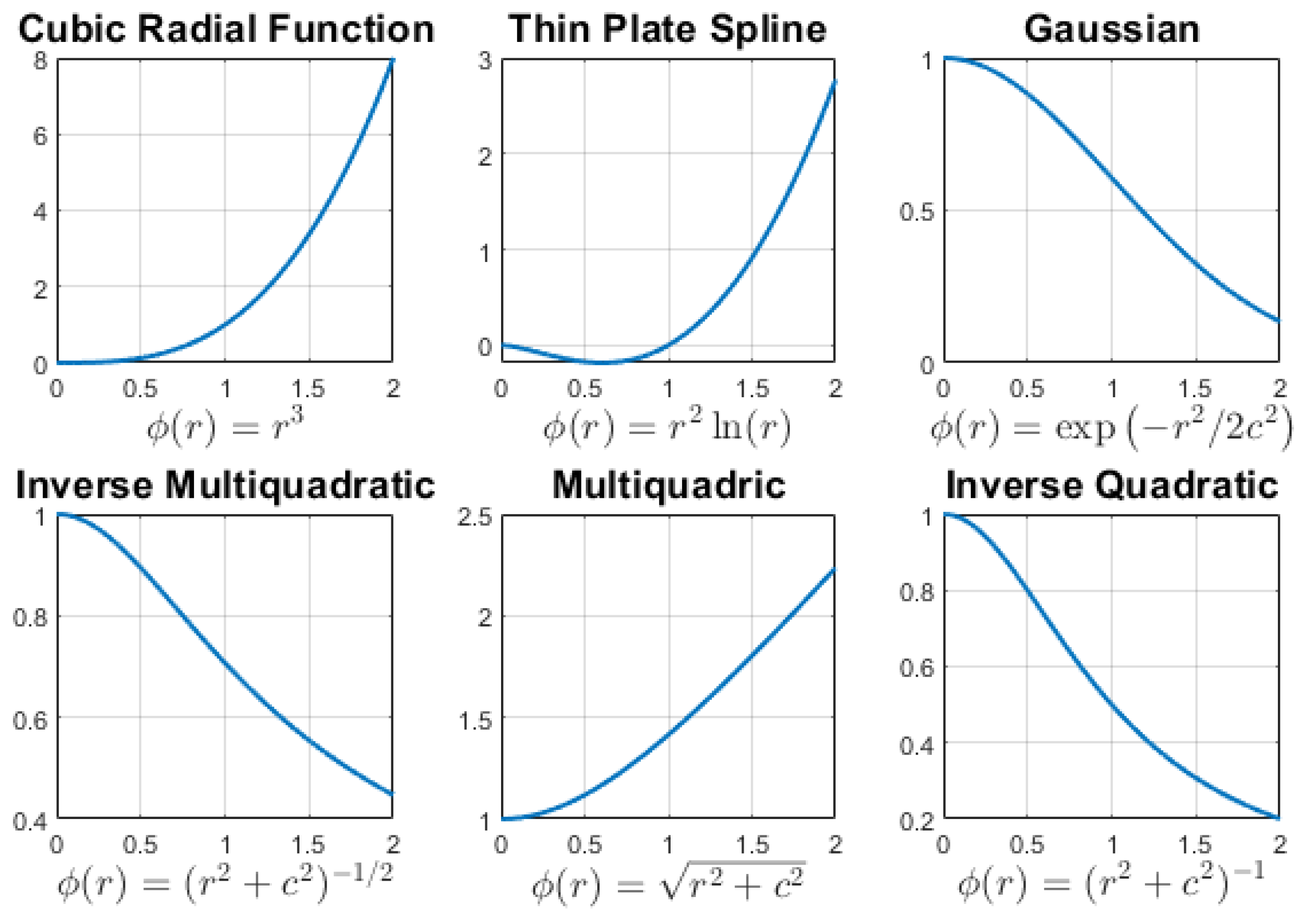
RBFs can be used to interpolate scattered data points, generating a smooth surface or function (Figure 1); common choices for RBFs are listed in Table 1.
Typically, r represents the Euclidean distance between a fixed center x * R d and a point x R d , i.e., 
r = x x * 2 .
Thus, an RBF is a function of this distance.
The shape parameter c controls the spread of the RBFs and significantly influences the performance of the method. The convergence, stability, and accuracy of RBF methods strongly depend on both the shape parameter and the choice of radial basis function.
Taking the interpolating RBF approximation as:
F ( x ) = i = 1 N λ i ϕ i ( x )
where ϕ i ( x ) = ϕ ( x x i ) and λ i are unknown scalars for i = 1 , , N , we obtain the following linear system:
ϕ ( x 1 x 1 ) ϕ ( x 1 x 2 ) ϕ ( x 1 x N ) ϕ ( x 2 x 1 ) ϕ ( x 2 x 2 ) ϕ ( x 2 x N ) ϕ ( x N x 1 ) ϕ ( x N x 2 ) ϕ ( x N x N ) λ 1 λ 2 λ N = f 1 f 2 f N
or more compactly,
A λ = f .
The matrix A, known as the collocation matrix, is positive definite and hence non-singular (invertible). Solving this linear system provides the interpolation coefficients.
However, the collocation matrix is often severely ill-conditioned, and the performance and accuracy of the RBF method depend significantly on the chosen RBF and its shape parameter. A poor choice of shape parameter can result in large numerical errors or instability. Therefore, selecting an optimal shape parameter is critical to maintaining accuracy while avoiding ill-conditioning.

2.2. 1D Parabolic Inverse Problem with Energy Overspecification

We consider the one-dimensional parabolic inverse problem described in Equations (1)–(5).
Using the transformation:
r ( t ) = exp 0 t p ( s ) d s
and
u ( x , t ) = r ( t ) ω ( x , t ) ,
the above inverse problem can be transformed into the following equivalent direct problem:
u t = u x x + r ( t ) φ ( x , t ) , 0 x 1 , 0 < t T ,
with the initial condition:
u ( x , 0 ) = f ( x ) , 0 x 1 ,
and boundary conditions:
u ( 0 , t ) = r ( t ) g 0 ( t ) , 0 < t T ,
u ( 1 , t ) = r ( t ) g 1 ( t ) , 0 < t T .
If E ( t ) 0 , then r ( t ) is obtained from the overspecification condition as:
r ( t ) = u ( x * , t ) E ( t ) .
Note that the source parameter p ( t ) is eliminated, and the problem defined by Equations (11)–(15) can now be treated as a direct problem.
To solve this direct problem, we apply the RBF method for both spatial and temporal discretization. The solution to the problem (11)–(14) is sought in the form:
u ˜ ( x , t ) = i = 1 M λ i ϕ i ( x , t ) ,
where ϕ i ( x , t ) = ϕ ( ( x , t ) ( x i , t i ) ) , and  λ i are the unknown coefficients to be determined for i = 1 , , M . The collocation technique is used to determine the coefficients λ i , i = 1 , , M .
As the first step, we discretize the problem domain. Let
Ω = { ( x i , t n ) , 0 x i 1 , 0 t n T }
and define the collocation set as
Ω = Ω 1 Ω 2 Ω 3 Ω 4 ,
where:
Ω 1 = { ( x i , t n ) , 0 x i 1 , t n = 0 , i = 1 , , M , n = 1 , , N } ,
Ω 2 = { ( x i , t n ) , x i = 0 , 0 < t n T , i = 1 , , M , n = 1 , , N } ,
Ω 3 = { ( x i , t n ) , x i = 1 , 0 < t n T , i = 1 , , M , n = 1 , , N } ,
Ω 4 = { ( x i , t n ) , 0 < x i < 1 , 0 < t n T , i = 1 , , M , n = 1 , , N } .
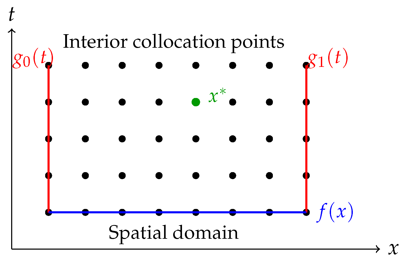
Figure 2 and Table 2 summarizes the regions and corresponding conditions in the discretized space–time domain.
By discretizing the reformulated direct problem using the RBF method, the following linear system of equations is obtained:
i = 1 M ϕ i ( x i , t n ) λ i = f ( x i ) , ( x i , t n ) Ω 1 ,
i = 1 M E ( t n ) ϕ i ( x i , t n ) ϕ i ( x * , t n ) g 0 ( t n ) λ i = 0 , ( x i , t n ) Ω 2 ,
i = 1 M E ( t n ) ϕ i ( x i , t n ) ϕ i ( x * , t n ) g 1 ( t n ) λ i = 0 , ( x i , t n ) Ω 3 ,
i = 1 M E ( t n ) ( ϕ i ( x i , t n ) ) t E ( t n ) 2 ( ϕ i ( x i , t n ) ) x 2 ϕ i ( x * , t n ) φ ( x i , t n ) λ i = 0 , ( x i , t n ) Ω 4 .
Solving this linear system yields the approximate solution to the transformed problem (11)–(14).
Using Equation (15), the approximation of r ( t ) is computed as:
r ˜ ( t ) = u ˜ ( x * , t ) E ( t ) .
Thus, the approximate solution of the original problem (1)–(5) is:
ω ˜ ( x , t ) = u ˜ ( x , t ) r ˜ ( t )
and the approximate value of p ( t ) is then obtained by:
p ˜ ( t ) = r ˜ ( t ) r ˜ ( t ) .
The radial basis approximation in the spatial domain, for each fixed time t, is given by:
u ˜ ( x , t ) = i = 1 M λ i ( t ) ϕ i ( x x i ) .
Substituting this into Equation (11), we obtain:
i = 1 M λ i ( t ) ϕ i ( x x i ) = i = 1 M λ i ( t ) ϕ i ( x x i ) + r ( t ) φ ( x , t ) .
For numerical computation, Equation (29) is discretized using a simple one-step forward difference in time, resulting in:
i = 1 M λ i ( t n + 1 ) ϕ ( x x i ) = i = 1 M λ i ( t n ) ϕ ( x x i ) + Δ t i = 1 M λ i ( t n ) ϕ ( x x i ) + i = 1 M λ i ( t n ) ϕ ( x * x i ) E ( t n ) φ ( x , t n ) .
By substituting each x k for x, we obtain the following iterative system of equations:
u ( x k , t n + 1 ) = i = 1 M λ i ( t n + 1 ) ϕ ( x k x i ) = i = 1 M λ i ( t n ) ϕ ( x k x i ) + Δ t i = 1 M λ i ( t n ) ϕ ( x k x i ) + i = 1 M λ i ( t n ) ϕ ( x * x i ) E ( t n ) φ ( x k , t n ) .
Once u ( x k , t n ) is computed, we can evaluate the approximations for:
  • r ˜ ( t n ) using Equation (25);
  • ω ˜ ( x k , t n ) using Equation (26);
  • p ˜ ( t n ) using Equation (27).
Let M be the number of collocation nodes in the spatial domain, and  N = T / Δ t be the number of time steps, where Δ t is the time increment.
Then, the solution to the inverse problem (11)–(15) can be approximated using Algorithm 1 [9].

3. Results

3.1. Test Problem—1

We present a test example to evaluate the effectiveness of the radial basis function method for solving inverse parabolic partial differential equations [3]. This problem is selected because its analytical solution is known, enabling direct comparison and validation of the numerical method.
We consider the inverse problem defined by Equations (1)–(5) with the following test data:
(32a) f ( x ) = cos ( π x ) + sin ( π x ) , (32b) g 0 ( t ) = exp ( t 2 ) , (32c) g 1 ( t ) = exp ( t 2 ) , (32d) φ ( x , t ) = π 2 ( t + 1 ) 2 exp ( t 2 ) cos ( π x ) + sin ( π x ) , (32e) E ( t ) = 2 exp ( t 2 ) .
Let the internal measurement location be x * = 0.25 . Then, the exact solution is:
ω ( x , t ) = exp ( t 2 ) ( cos ( π x ) + sin ( π x ) ) ,
p ( t ) = 1 + t 2 .

3.1.1. Recovering Source Control Parameter

We compute the numerical solution using the GRBF. The spatial step sizes used are Δ x = 1 / 5 , 1 / 10 , 1 / 20 , and the corresponding time step is set as Δ t = ( Δ x / 4 ) 2 . Let x k = k Δ x and t n = n Δ t ; function values are sampled at these nodes.
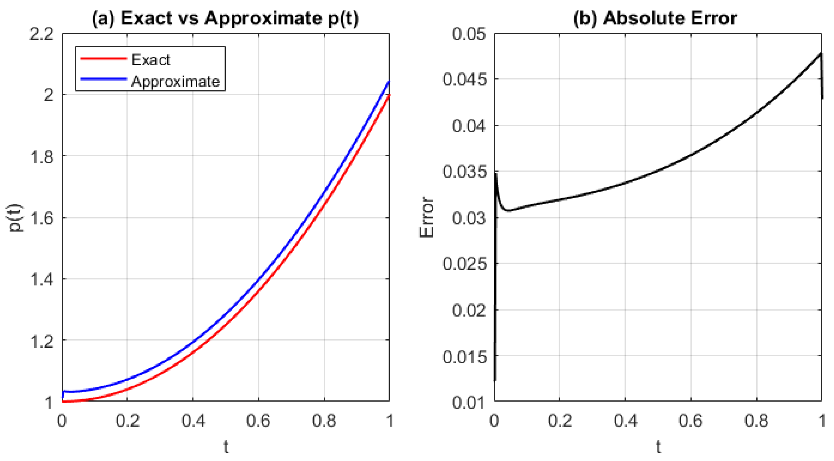
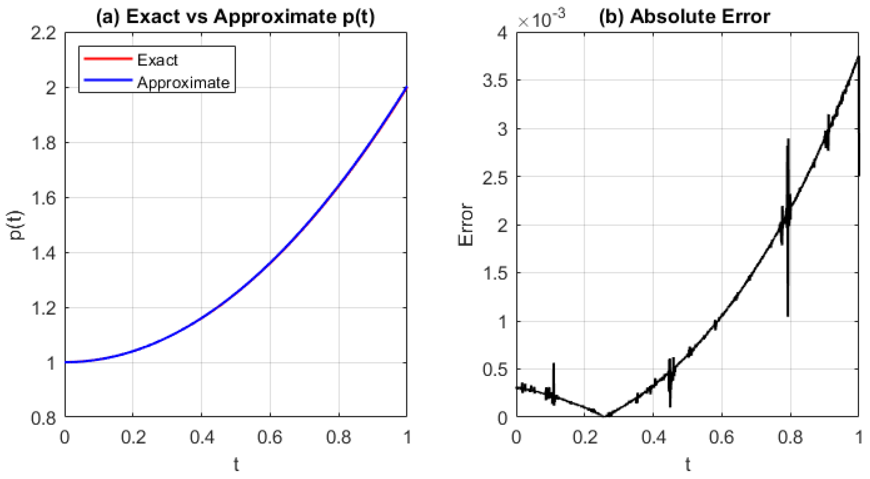
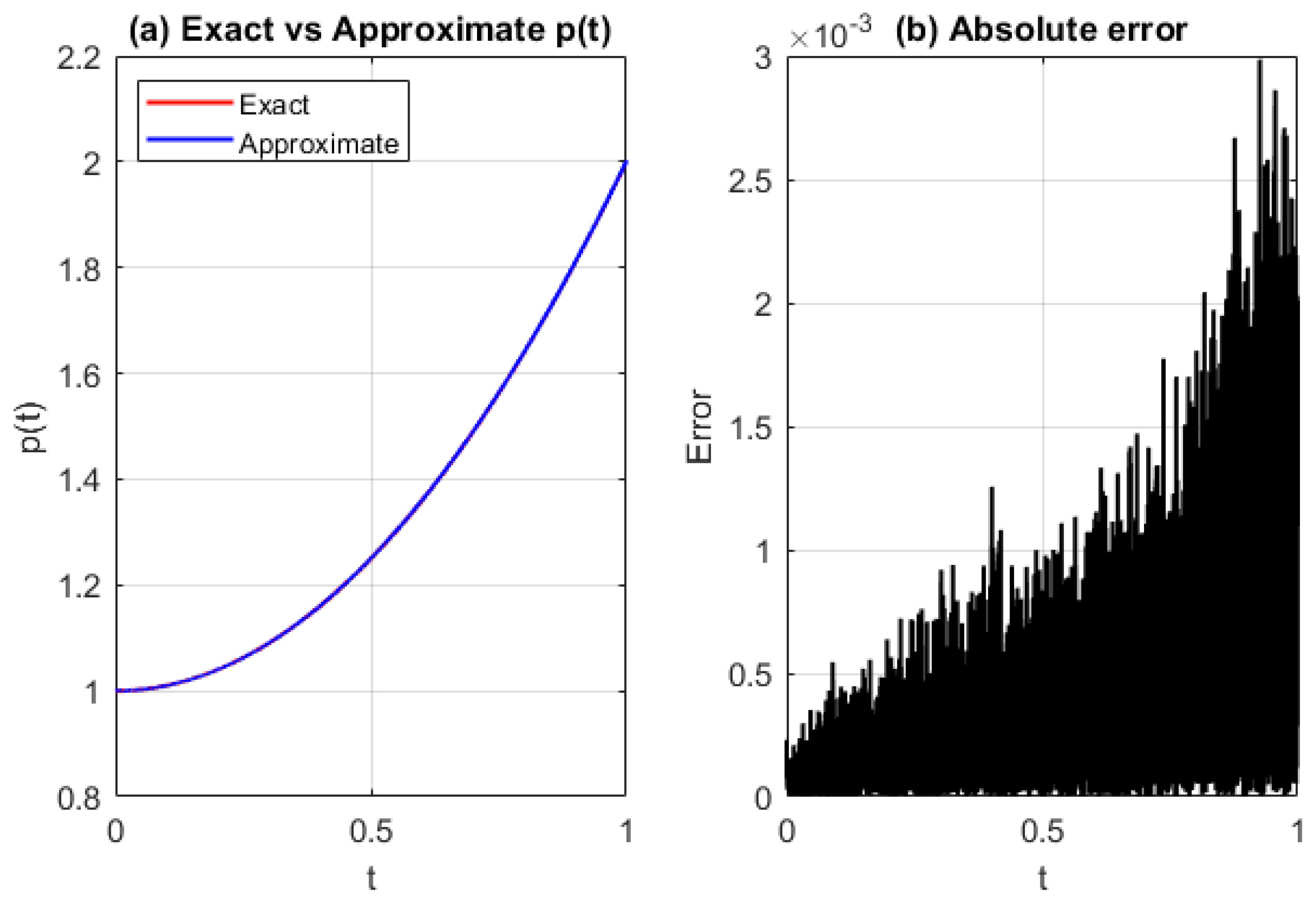
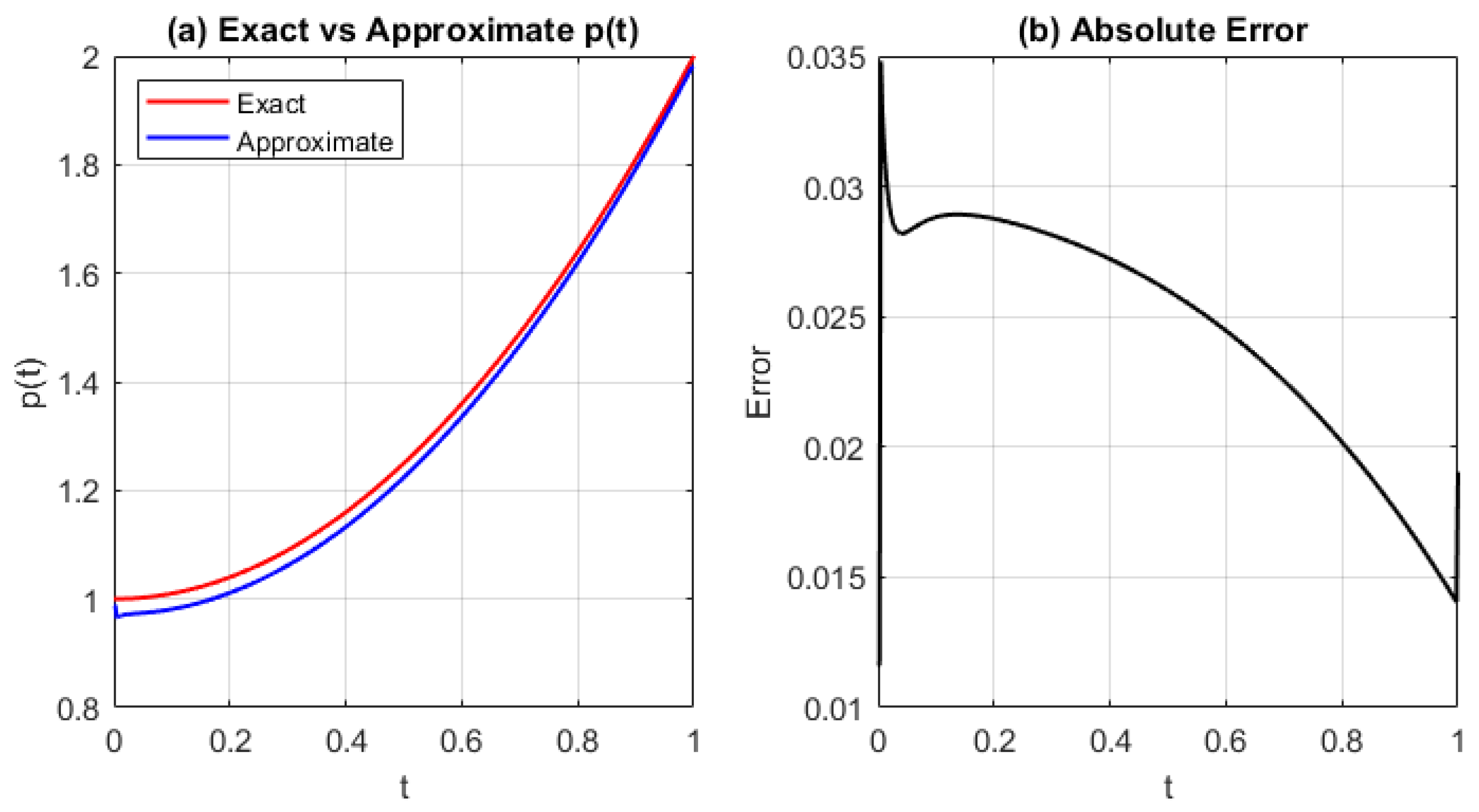
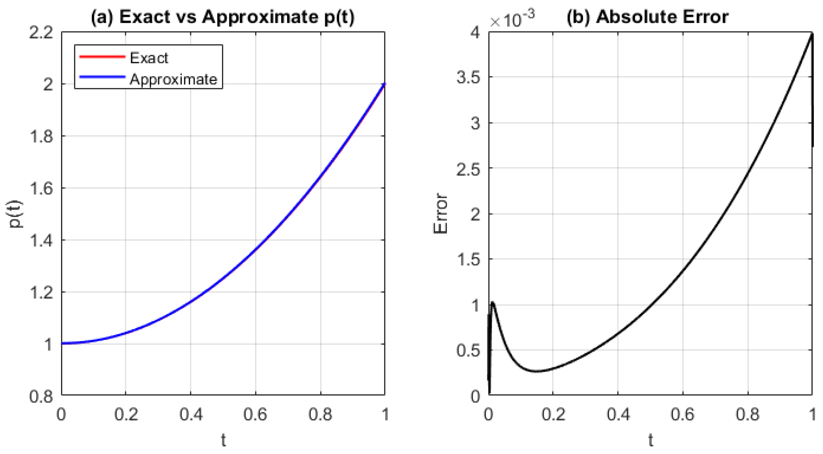
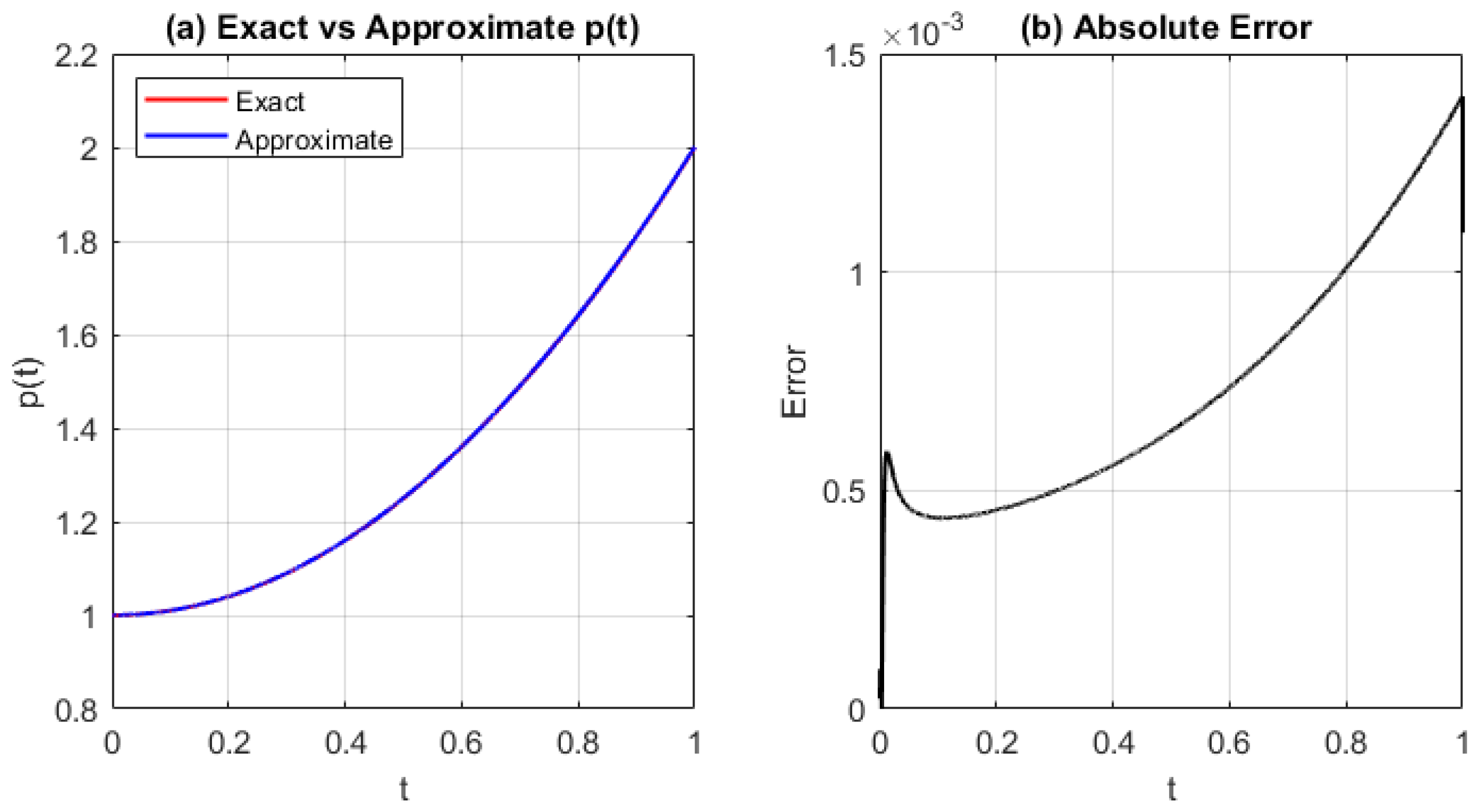
Figure 3, Figure 4 and Figure 5 show the exact and approximated source parameter p ( t ) , the numerical solution p ˜ ( t ) , and the absolute error | p ( t ) p ˜ ( t ) | . These results are obtained using the GRBF with shape parameter c = 10 Δ x , for different values of Δ x .
From Figure 3, Figure 4 and Figure 5, we observe that, except for the initial peak error—which arises due to inaccuracies in approximating the derivative of r ( t ) —the approximation error increases approximately linearly as time progresses. As shown in Line 19 of Algorithm 1, a central difference is used at interior points, while at t = 0 , the derivative is set to r ( t 1 ) (Line 23) to maintain stability without introducing a less accurate one-sided approximation.
Algorithm 1: RBF collocation method for 1D inverse parabolic problem
 1:
Input: Initial condition f ( x ) ; boundary data g 0 ( t ) , g 1 ( t ) ; energy data E ( t ) ; source term φ ( x , t ) ; shape parameter c; step sizes Δ x , Δ t ; final time T
 2:
Output: Approximate solution ω ˜ ( x , t ) ; source parameter p ˜ ( t )
 3:
Initialize t 0 = 0 , r ( t 0 ) = 1
 4:
Compute u ˜ ( x k , t 0 ) = f ( x k )
 5:
Solve for coefficients: λ ( t 0 ) = Φ 1 u ˜ ( t 0 )
 6:
for  n = 0 to N 1  do
 7:
       Compute u ˜ ( x k , t n + 1 ) via forward Euler:
 8:
            u ˜ ( x k , t n + 1 ) = u ˜ ( x k , t n ) + Δ t i λ i ( t n ) ϕ ( x k x i ) + r ˜ ( t n ) φ ( x k , t n )
 9:
       Update coefficients: λ ( t n + 1 ) = Φ 1 u ˜ ( t n + 1 )
10:
       Evaluate at overspecified point: u ( x * , t n + 1 ) = i λ i ( t n + 1 ) ϕ ( x * x i )
11:
       Compute r ˜ ( t n + 1 ) = u ( x * , t n + 1 ) / E ( t n + 1 )
12:
       Apply boundary conditions:
13:
            u ˜ ( 0 , t n + 1 ) = r ˜ ( t n + 1 ) g 0 ( t n + 1 )
14:
            u ˜ ( 1 , t n + 1 ) = r ˜ ( t n + 1 ) g 1 ( t n + 1 )
15: 
       Recompute λ ( t n + 1 ) accordingly
16: 
end for
17: 
for  n = 0 to N do
18:
       Recover ω ˜ ( x , t n ) = u ˜ ( x , t n ) / r ˜ ( t n )
19:
       Approximate r ˜ ( t n ) r ˜ ( t n + 1 ) r ˜ ( t n 1 ) 2 Δ t
20:
       Compute p ˜ ( t n ) = r ˜ ( t n ) r ˜ ( t n )
21: 
end for
22: 
Handle endpoints:
23:
    r ˜ ( t 0 ) = r ˜ ( t 1 ) , r ˜ ( T ) = r ˜ ( T Δ t )
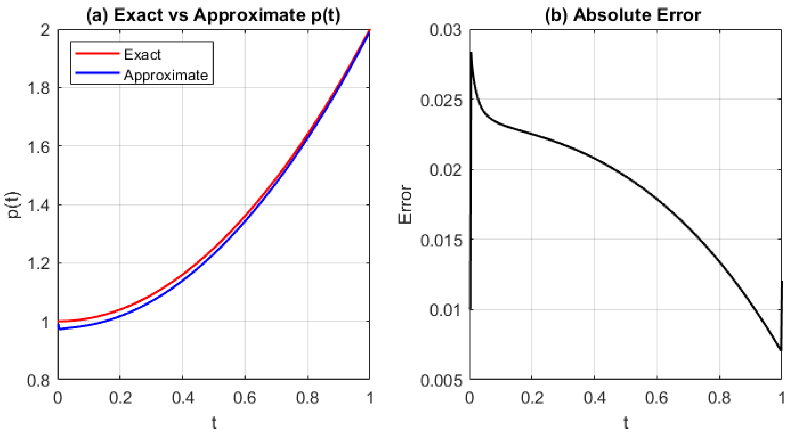
Figure 6, Figure 7 and Figure 8 show the approximation of the source control parameter p ( t ) , the corresponding numerical solution p ˜ ( t ) , and the error using the MQRBF. These results are obtained with shape parameter c = 10 Δ x and step sizes Δ x = 1 / 5 , 1 / 10 , 1 / 20 .
We observe from Figure 6, Figure 7 and Figure 8 that the error increases with larger spatial step sizes, indicating that finer spatial discretization improves stability and accuracy for MQRBF approximations.
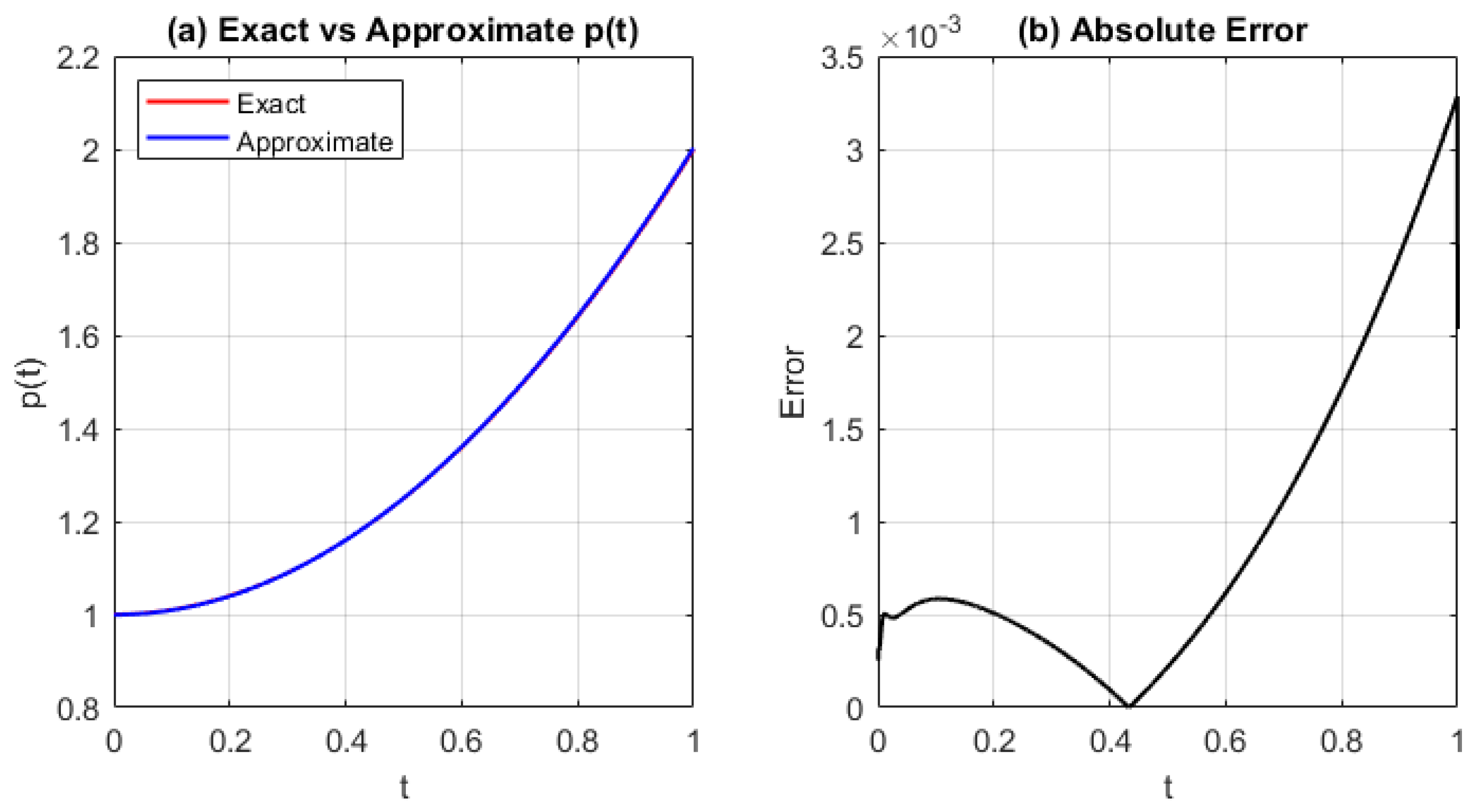
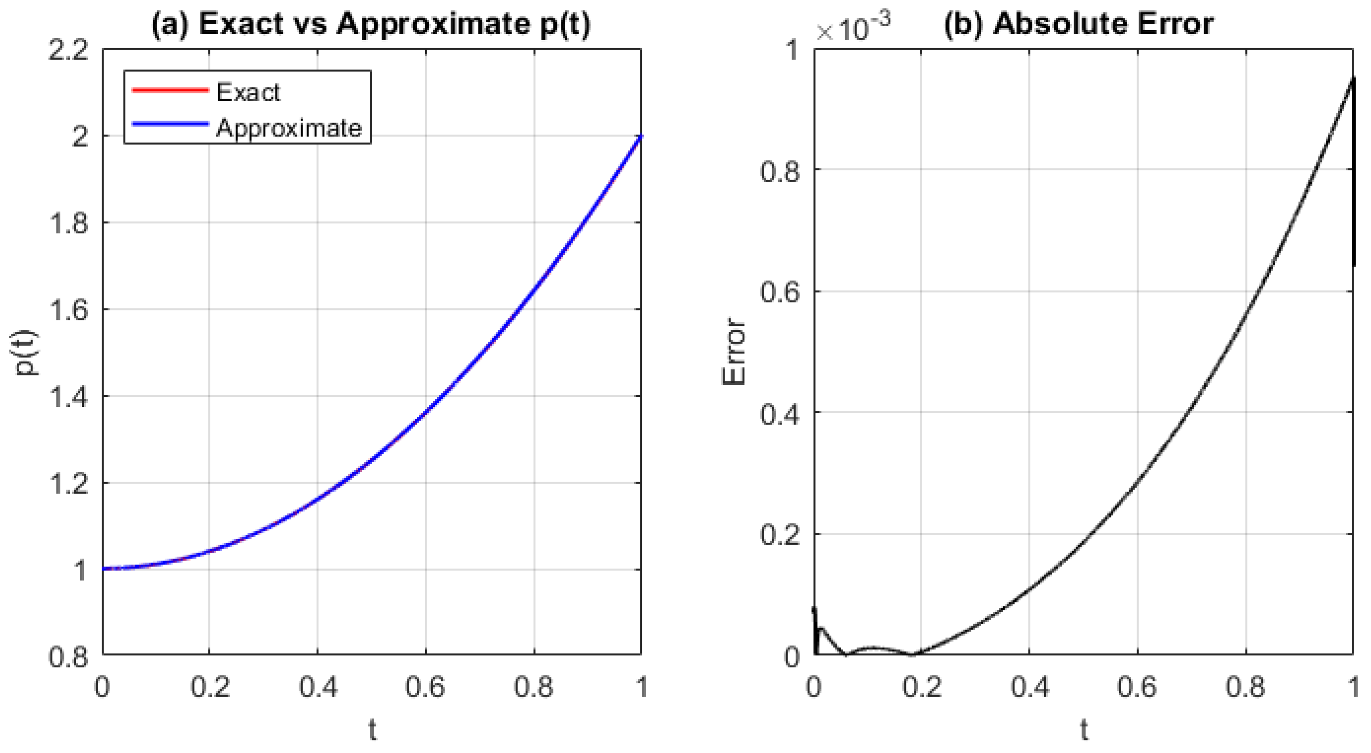
Figure 9, Figure 10 and Figure 11 show the source control parameter p ( t ) , its approximated solution p ˜ ( t ) , and the corresponding error using the IMQRBF with shape parameter c = 10 Δ x and step sizes Δ x = 1 / 5 , 1 / 10 , 1 / 20 .
As observed in Figure 9, Figure 10 and Figure 11, the approximation error exhibits behavior similar to that obtained using the GRBF and MQRBF.

3.1.2. Comparison of Different Radial Basis Functions

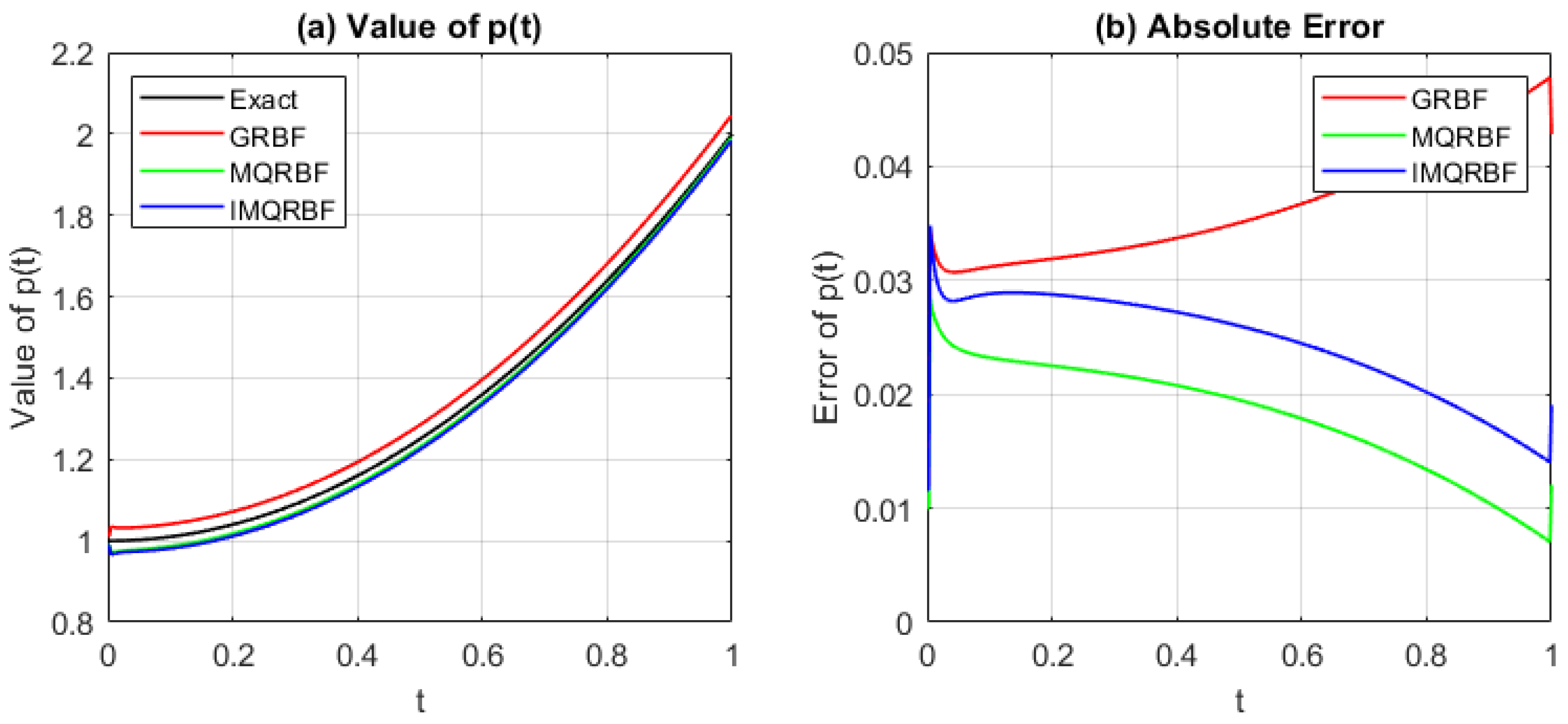
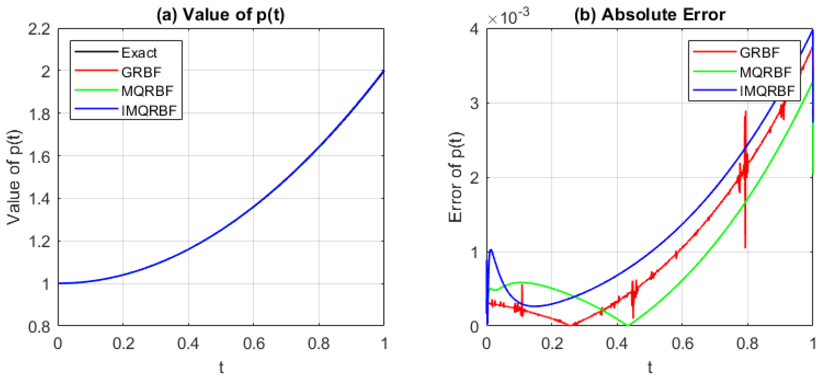
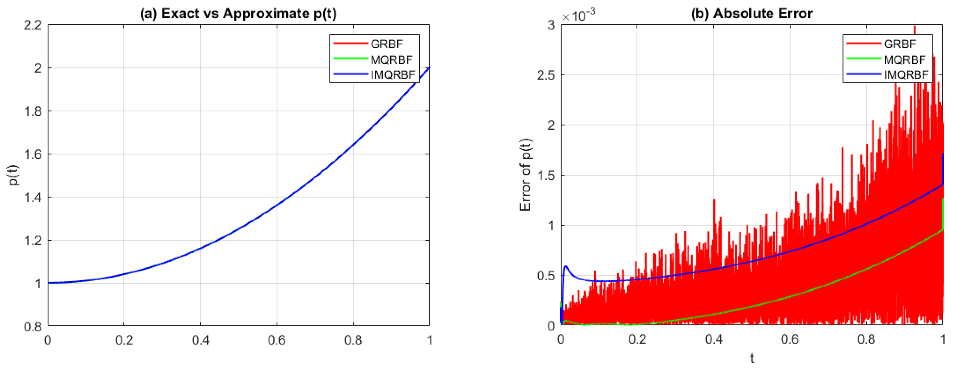
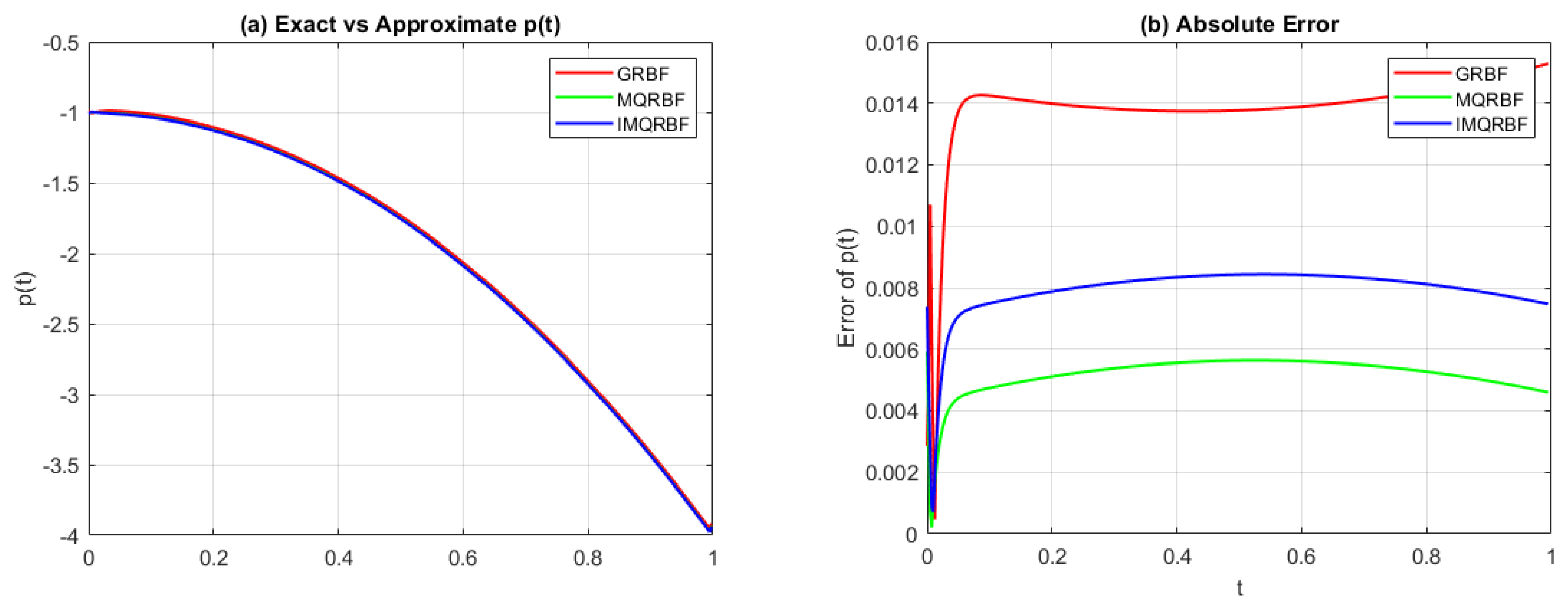
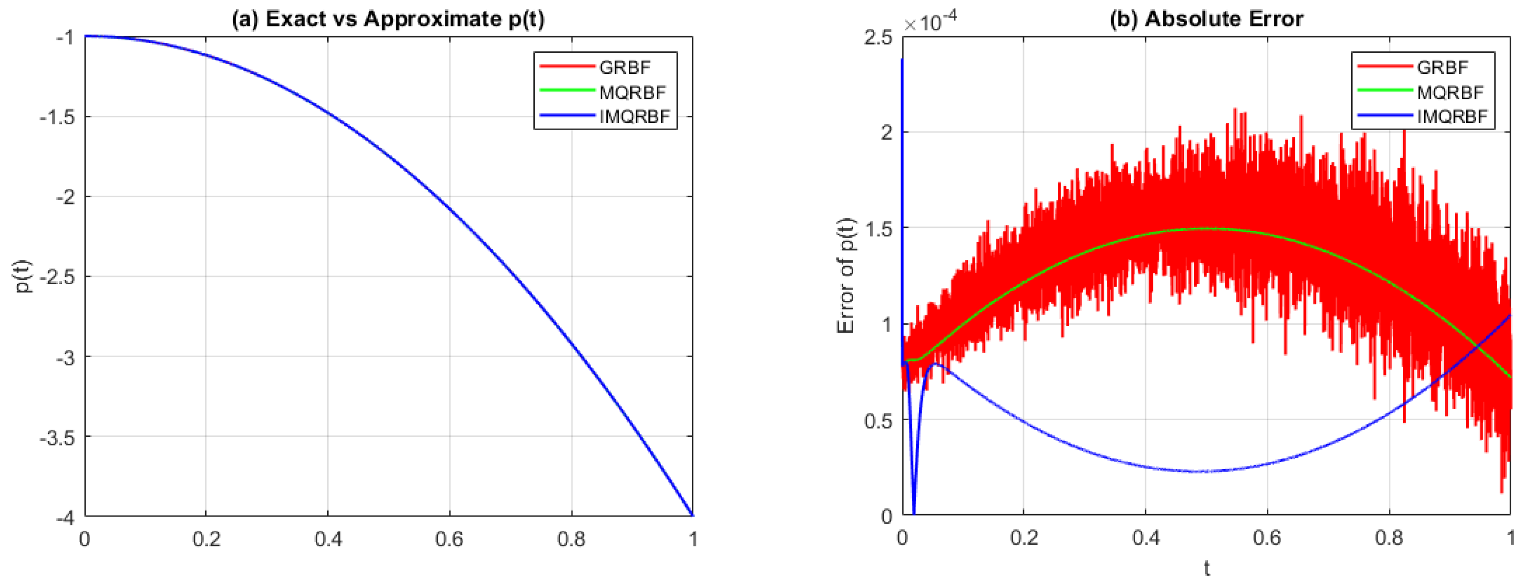
Figure 12, Figure 13 and Figure 14 compare the approximated source function p ˜ ( t ) and the corresponding absolute error | p ( t ) p ˜ ( t ) | using the GRBF, MQRBF, and IMQRBF. All simulations are performed with shape parameter c = 10 Δ x and spatial steps Δ x = 1 / 5 , 1 / 10 , 1 / 20 .
From Figure 12, it is evident that the MQRBF outperforms both the GRBF and MQRBF at this resolution.
Aside from minor fluctuations due to numerical discretization, Figure 12, Figure 13 and Figure 14 indicate that the MQRBF outperforms both the GRBF and IMQRBF as a suitable choice for step sizes Δ x = 1 / 5 , Δ x = 1 / 10 , and Δ x = 1 / 20 .

3.1.3. Error in Reconstructing the Function ω ( x , t )

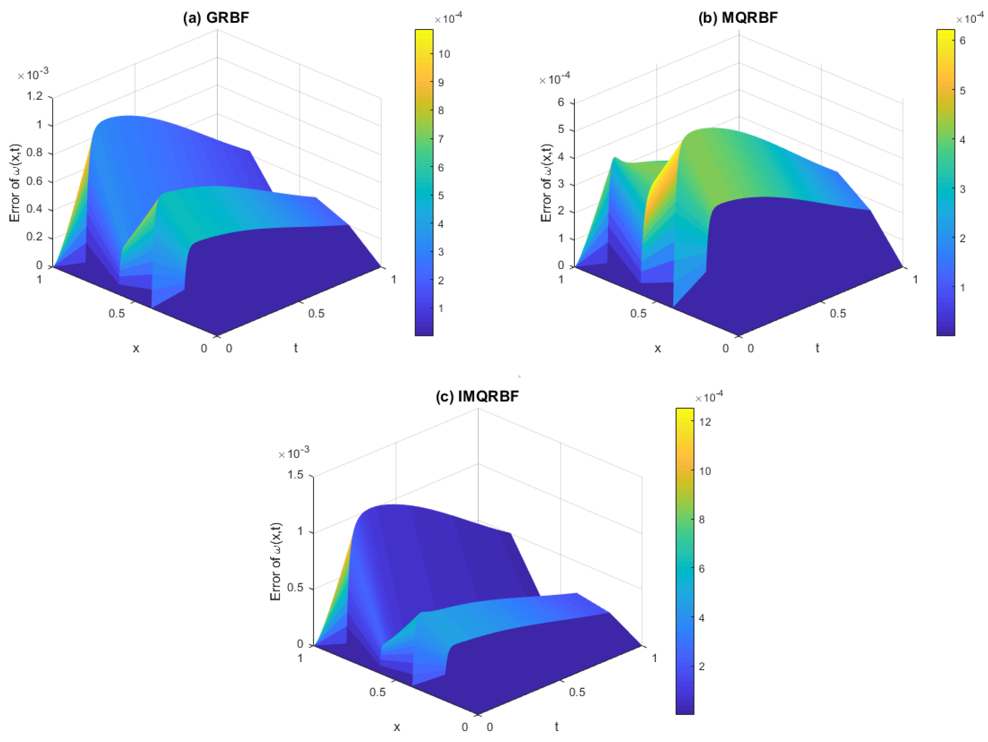
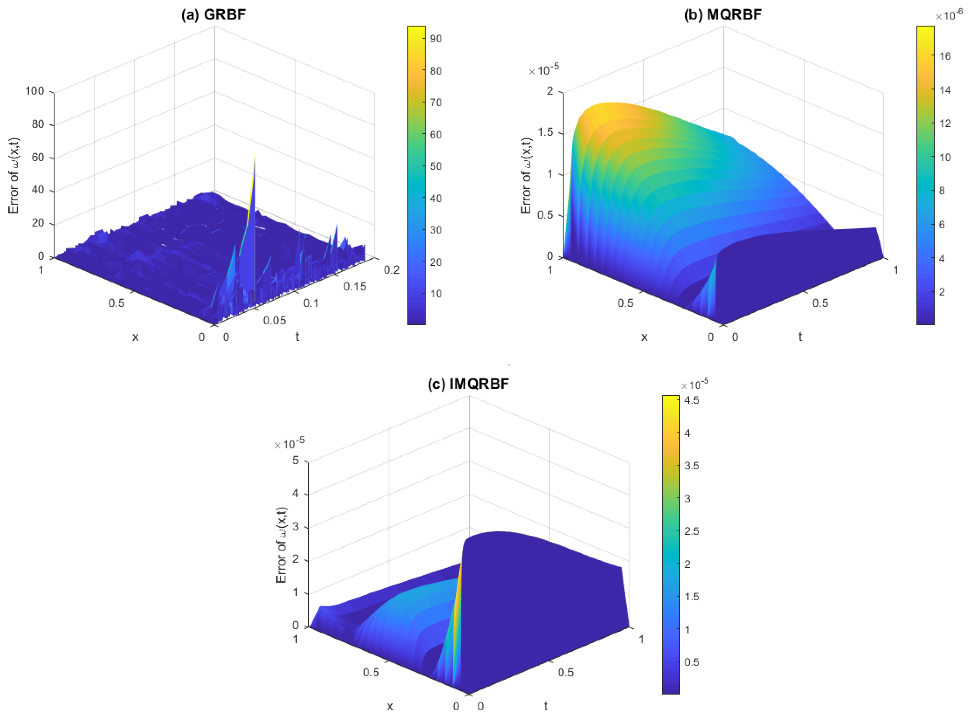
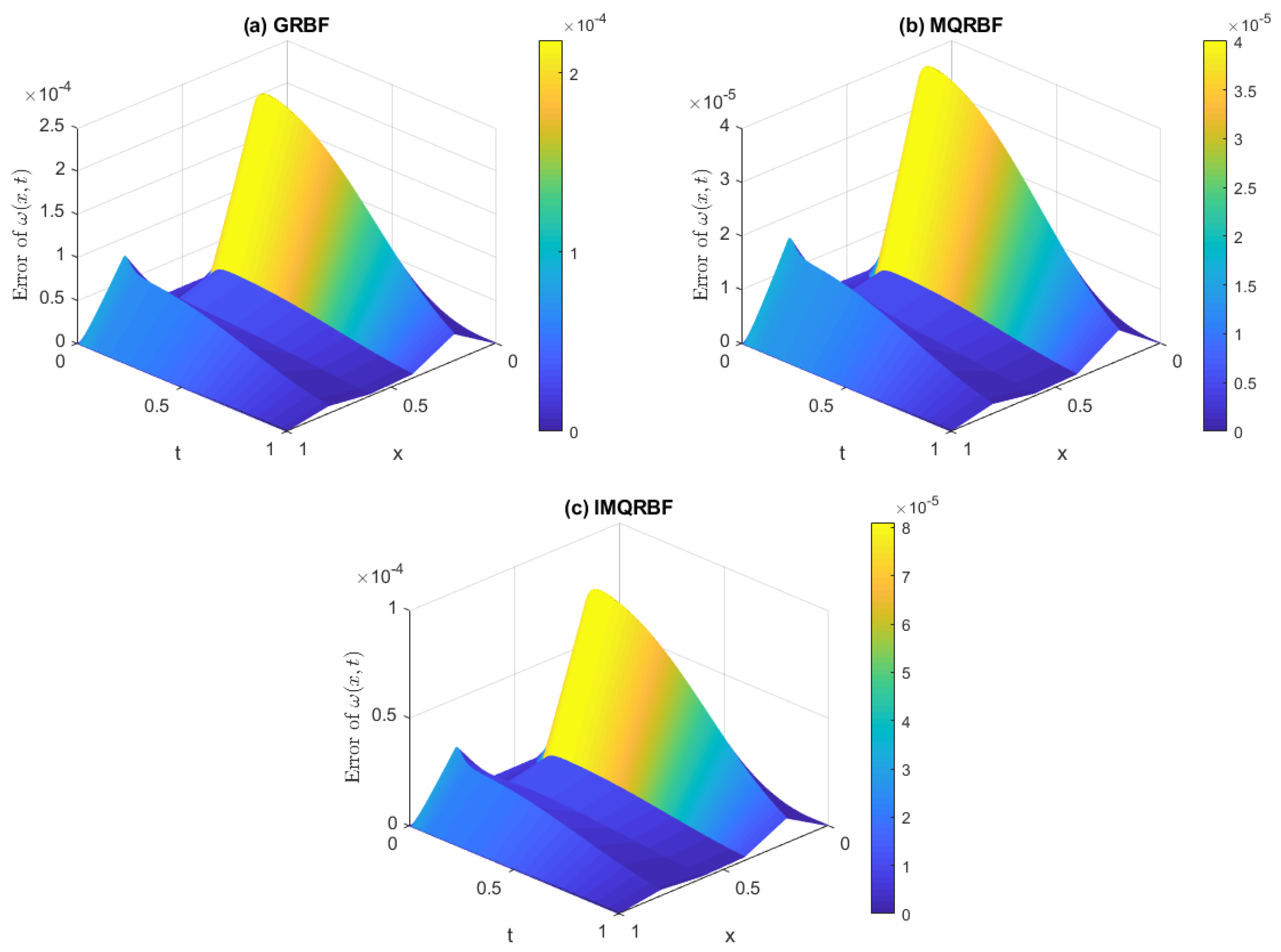
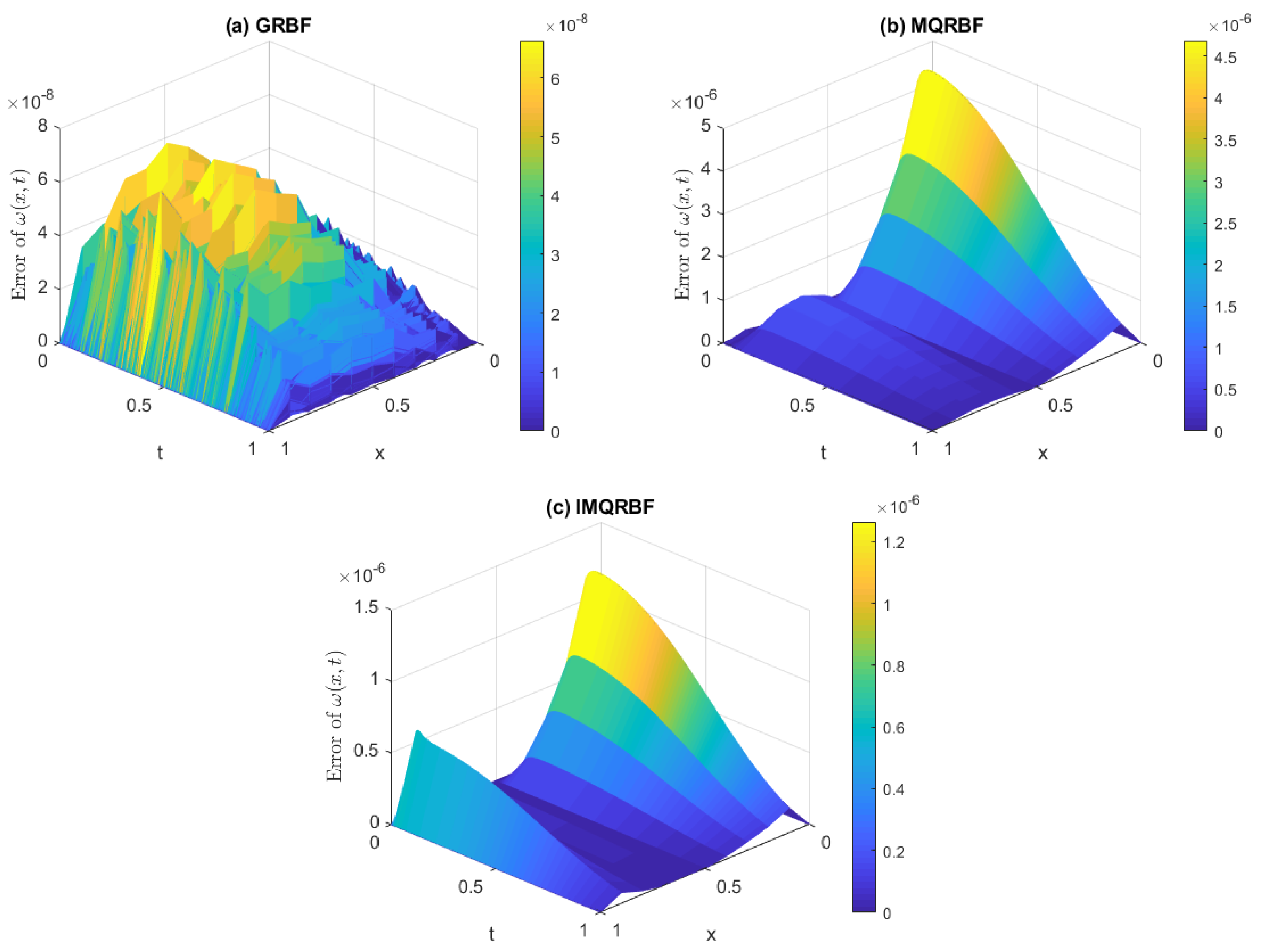
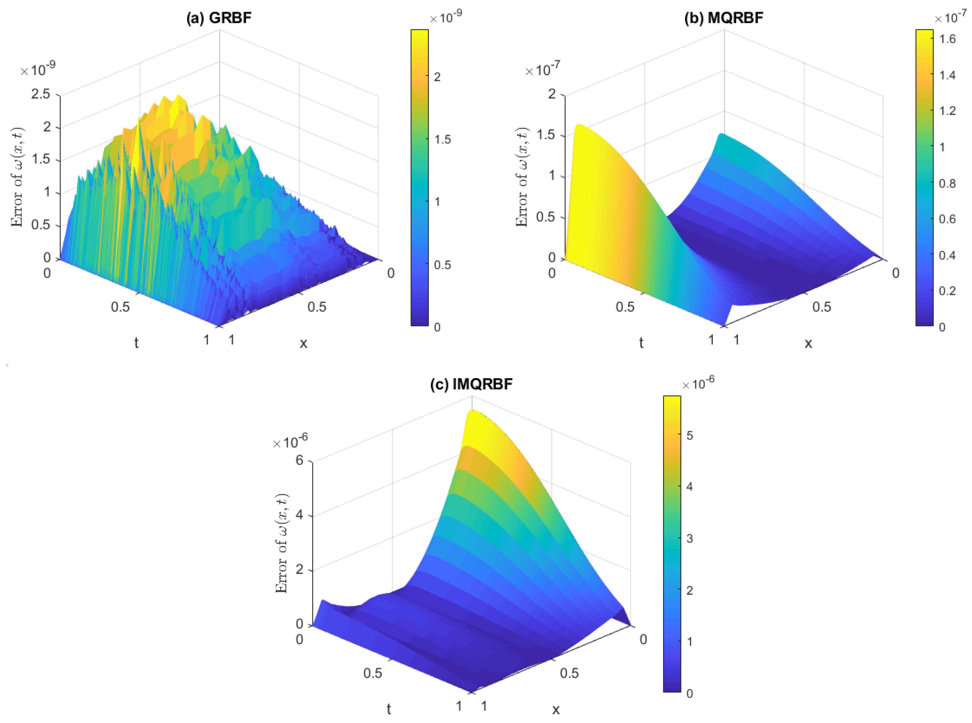
Figure 15, Figure 16 and Figure 17 plot the corresponding error function | ω ( x , t ) ω ˜ ( x , t ) | using GRBF, MQRBF, and IMQRBF with shape parameter c = 10 Δ x and spatial step sizes Δ x = 1 / 5 , 1 / 10 , 1 / 20 , respectively.
It is clear from Figure 15, Figure 16 and Figure 17 that MQRBF outperforms the other two choices of RBFs—namely, the GBRF and IMQRBFs—in terms of accuracy.
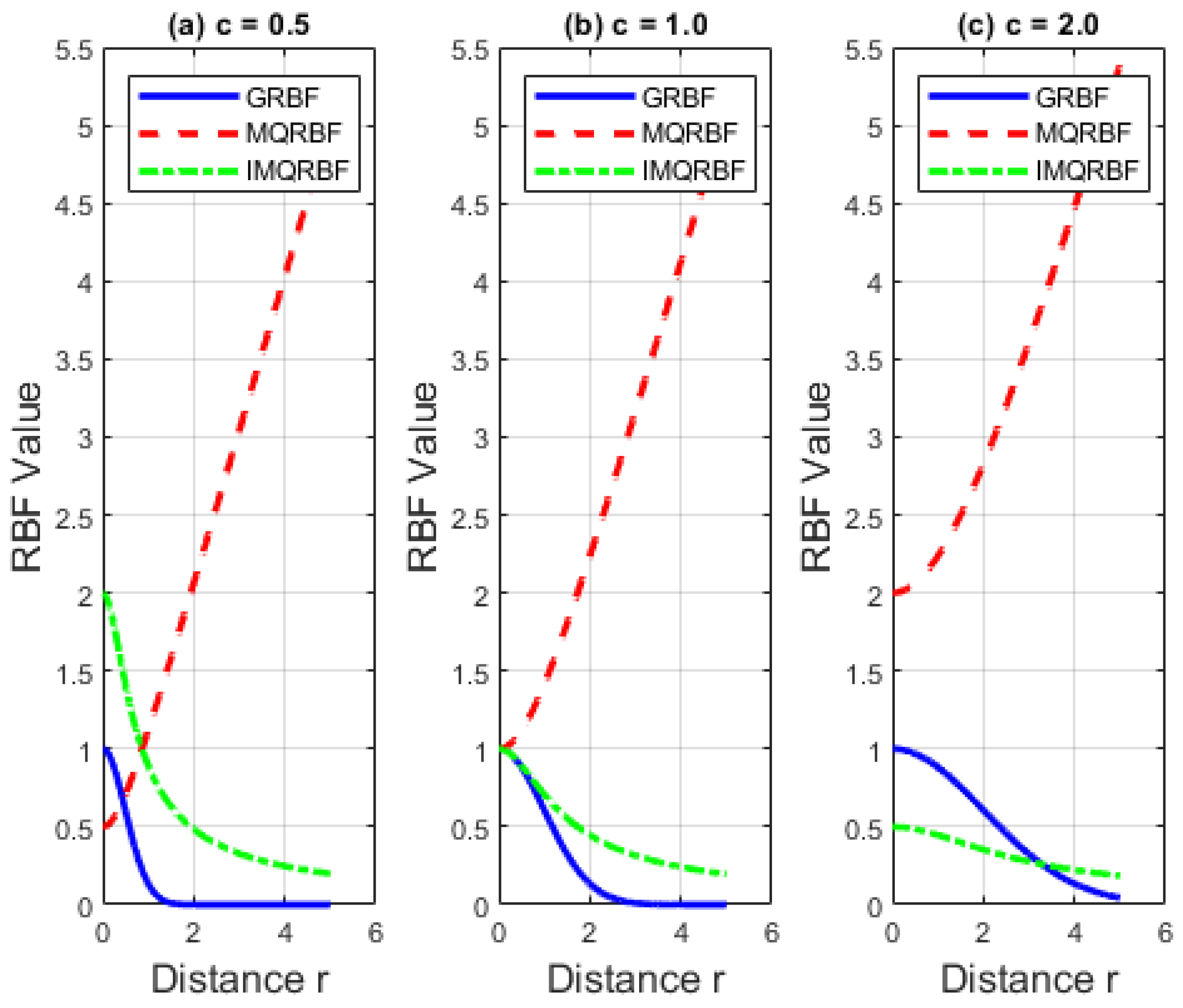
The observed differences in reconstruction accuracy among GRBF, MQRBF, and IMQRBF stem from their distinct functional forms and decay rates, as shown in Figure 18. While GRBF is highly localized and IMQRBF offers smooth decay, MQRBF provides a favorable balance between flexibility and stability. Its unbounded growth allows for better feature capture without excessive sensitivity to the shape parameter, contributing to its superior accuracy and robustness in reconstruction.

3.1.4. Optimal Choice of Shape Parameter

Table 3, Table 4 and Table 5 present the maximum error norm E and the E 2 error norm for the approximation error in ω ( x , t ) , computed using GRBF, MQRBF, and IMQRBF for various shape parameter values c = 0.2 , 0.5 , 1 , 1.5 , 2 , 2.5 , 3 , 3.5 , 4.0 , 5.0 and spatial step sizes Δ x = 1 / 5 , 1 / 10 , 1 / 20 .
The maximum error norm is defined as:
E = max ω ( x i , t i ) ω ˜ ( x i , t i ) , for 1 i M .
The E 2 error norm is defined as:
E 2 = 1 M i = 1 M ω ( x i , t i ) ω ˜ ( x i , t i ) 2 .
Our results for the GRBF can be compared with those in Table 2 of the work by Limin Ma and Zongmin Wu [9], where a similar parabolic inverse problem was solved using the RBF method. Under comparable settings (e.g., spatial step size Δ x = 1 / 10 ), both have similar error orders.

3.2. Test Problem 2

Consider the problem defined by Equations (1)–(5) with the following data [10]:
(35a) f ( x ) = 1 2 sin ( x ) exp ( x 2 ) , (35b) g 0 ( t ) = 0 , (35c) g 1 ( t ) = 1 2 sin ( 1 ) exp ( t 3 t 2 1 ) , (35d) φ ( x , t ) = exp ( t 3 t 2 x 2 ) t sin ( x ) 2 sin ( x ) 2 x cos ( x ) + 2 x 2 sin ( x ) , (35e) E ( t ) = 1 2 sin 1 2 exp t 3 t 2 1 4 ,
and let x * = 0.5 . The exact solution is given by:
ω ( x , t ) = 1 2 sin ( x ) exp ( t 3 t 2 x 2 ) ,
p ( t ) = 3 t 2 1 .

3.2.1. Comparison of Different Radial Basis Functions

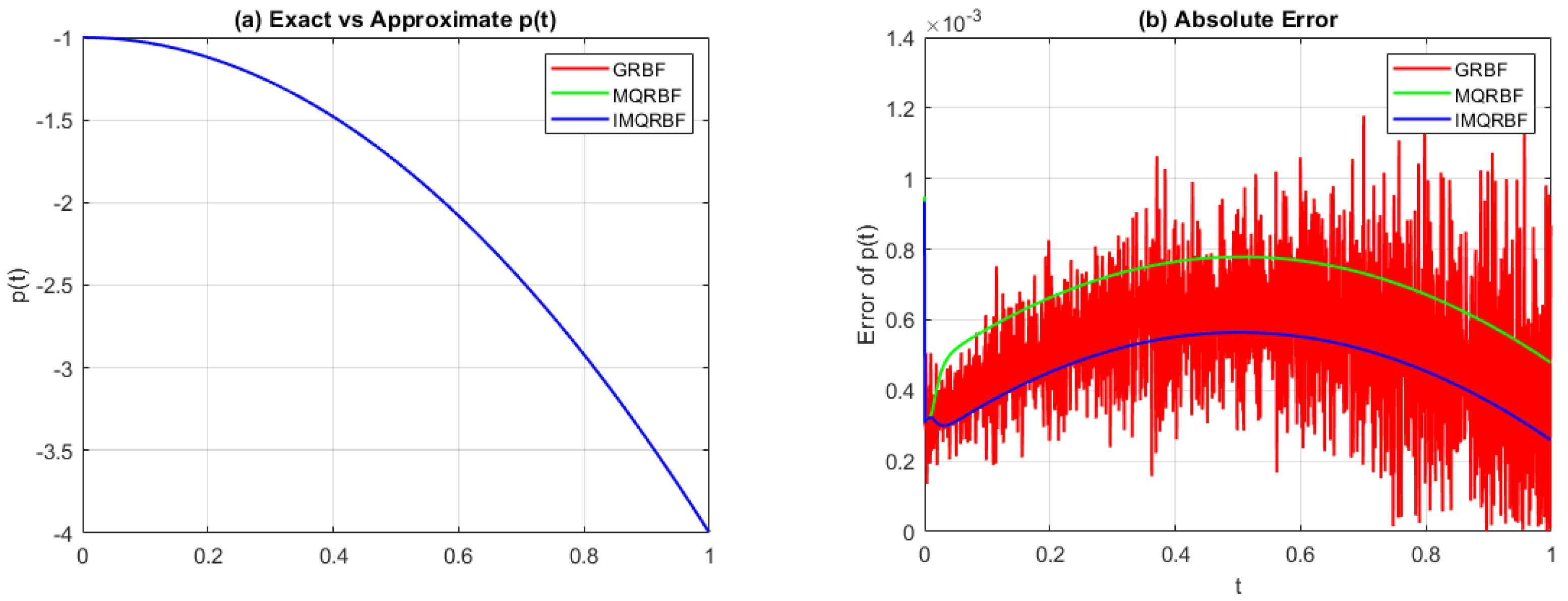
Figure 19, Figure 20 and Figure 21 plot the approximated source control parameter p ˜ ( t ) using GRBF, MQRBF, and IMQRBF, along with the corresponding error function, for shape parameter c = 10 Δ x and spatial step sizes Δ x = 1 / 5 , 1 / 10 , 1 / 20 .
From Figure 19, Figure 20 and Figure 21, it is observed that the error remains nearly constant throughout the domain, except near the endpoints. Furthermore, while the MQRBF yields the lowest error for the step size Δ x = 1 / 5 , the IMQRBF proves to be the most accurate method for finer step sizes Δ x = 1 / 10 and Δ x = 1 / 20 .

3.2.2. Comparative Analysis of the Solution ω ( x , t ) Using Various RBFs

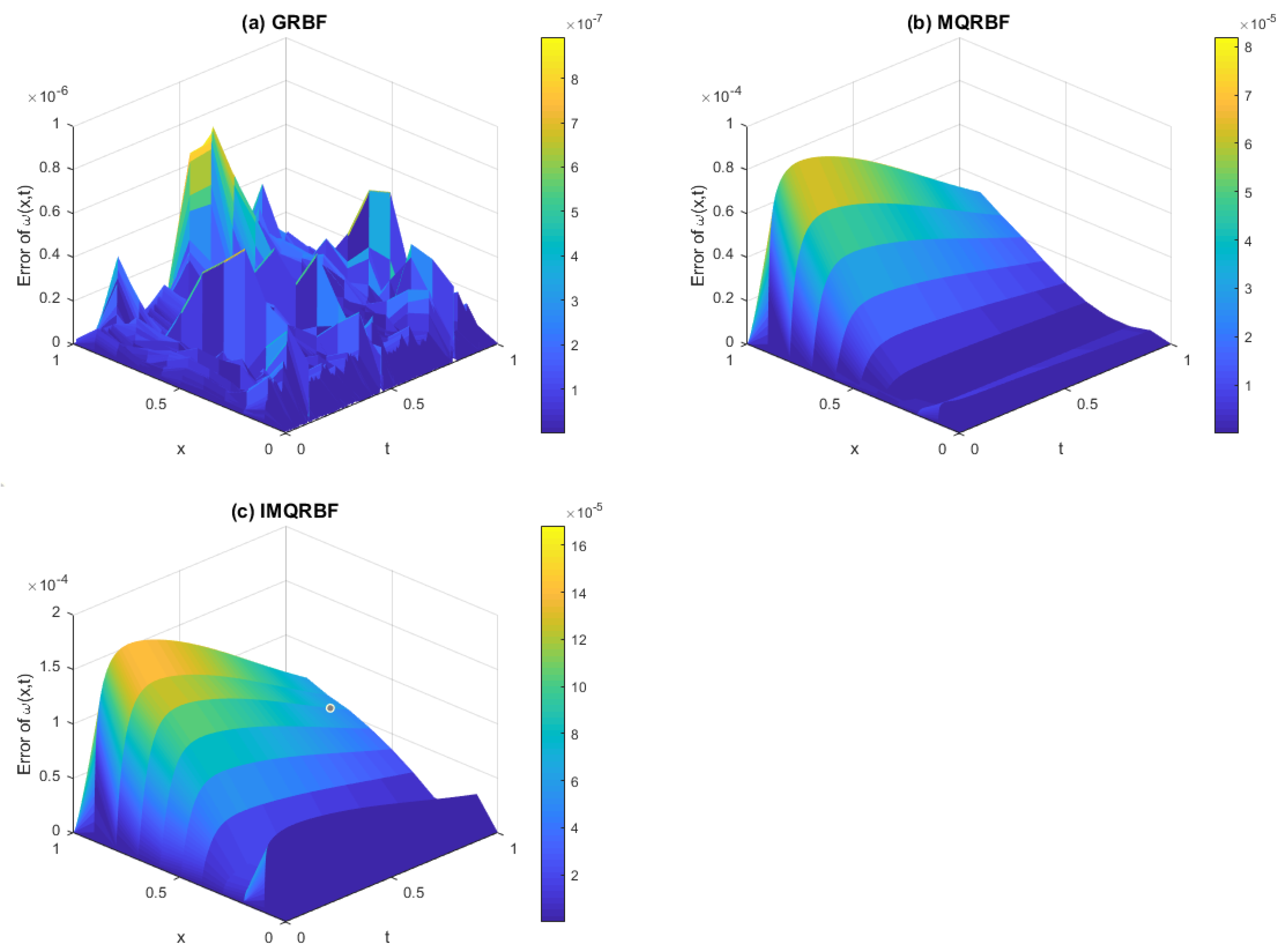
Figure 22, Figure 23 and Figure 24 plot the approximation error | ω ( x , t ) ω ˜ ( x , t ) | using GRBF, MQRBF, and IMQRBF with shape parameter c = 10 Δ x and spatial step sizes Δ x = 1 / 5 , 1 / 10 , 1 / 20 .
As the spatial resolution is refined from Δ x = 1 5 to 1 20 , similar trends persist across all cases. GRBF yields the lowest error magnitudes but suffers from strong fluctuations, reducing its reliability. MQRBF offers a good balance between accuracy and stability, while IMQRBF provides the most consistent and robust performance, with steadily improving accuracy under mesh refinement.

3.2.3. Optimal Choice of Shape Parameter

Table 6, Table 7 and Table 8 list the maximum error norm E and the E 2 error norm for the approximation error in ω ( x , t ) , computed using GRBF, MQRBF, and IMQRBF for shape parameter values c = 0.2 , 0.5 , 1 , 1.5 , 2 , 2.5 , 3 , 3.5 , 4.0 , 5.0 and spatial step sizes Δ x = 1 / 5 , 1 / 10 , 1 / 20 for Test Problem 2.
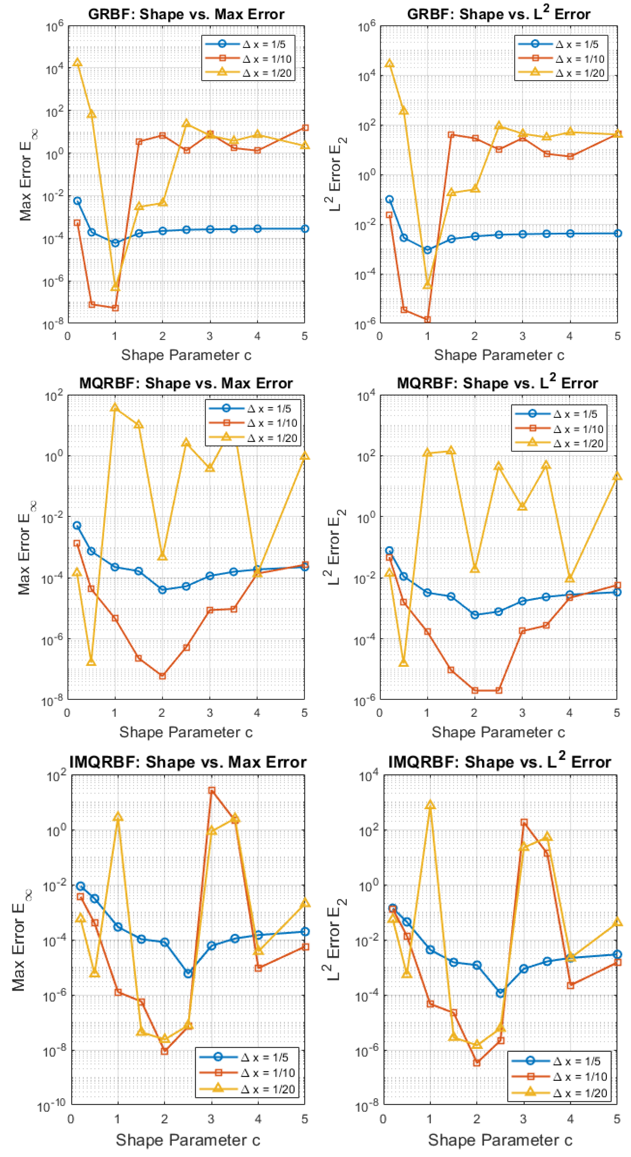
From Table 6, Table 7 and Table 8, it can be observed that the optimal shape parameters, based on both the E and E 2 error norms, are c = 1 for GRBF, c = 2 for MQRBF, and  c = 2 or 2.5 for IMQRBF.
Figure 25 illustrates how the shape parameter c influences the approximation error for the GRBF, MQRBF, and IMQRBF across three spatial resolutions.
For GRBF, the error decreases toward c = 1 , then increases rapidly due to ill-conditioning. GRBF is highly sensitive to shape parameter tuning and becomes unstable at fine resolutions.
MQRBF shows more consistent behavior across shape parameters and is the most robust among the three, achieving optimal accuracy around c = 2 .
IMQRBF maintains low error across all c values and grid resolutions, with best performance for c = 2 .

3.2.4. CPU Time Analysis

Simulations were performed using MATLAB R2019a on a Windows 11 Pro laptop with an Intel Core i5-1135G7 CPU and 16 GB RAM. CPU times were measured using tic and toc.
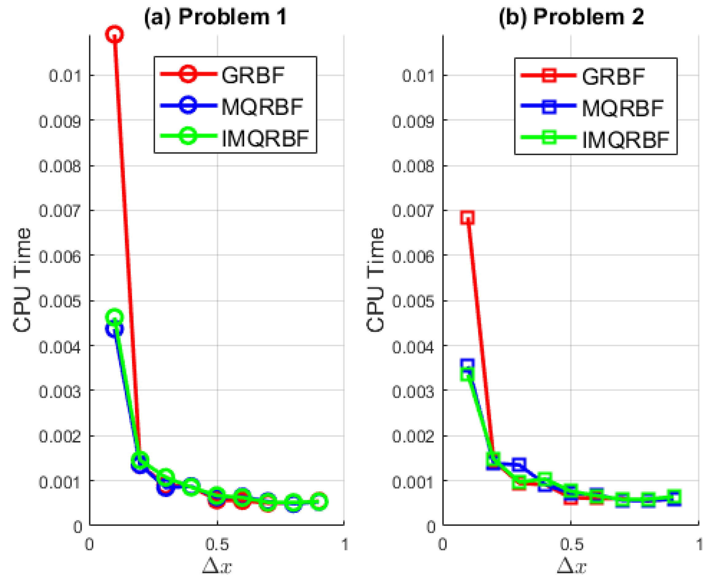
Figure 26 and Table 9 show the variation in CPU time for the three RBF methods—GRBF, MQRBF, and IMQRBF—applied to the two test problems over a range of spatial step sizes Δ x [ 0.1 , 0.9 ] .
For both problems, CPU time increases significantly as the spatial grid is refined (i.e., as Δ x approaches 0.1), which is consistent with the growth in computational cost due to larger system sizes. For Δ x 0.2 , CPU time stabilizes with minimal variation, indicating that matrix operations dominate primarily at finer resolutions. This suggests that the computational effort is less sensitive to the choice of RBF when the grid is relatively coarse.
At Δ x = 0.1 , the GRBF method exhibits a pronounced peak in CPU time—particularly for Problem 1—suggesting possible ill-conditioning of the interpolation matrix due to closely spaced nodes.
Overall, the MQRBF and IMQRBF methods demonstrate better scalability and robustness across the full range of Δ x , while GRBF becomes inefficient and unstable at fine discretizations. The trends are consistent across both test problems, though slight variations in cost are observed depending on the problem structure.

3.3. Condition Numbers ( k )

The condition number of a matrix A is defined as
k s ( A ) = A s · A 1 s , where s = 1 , 2 , .
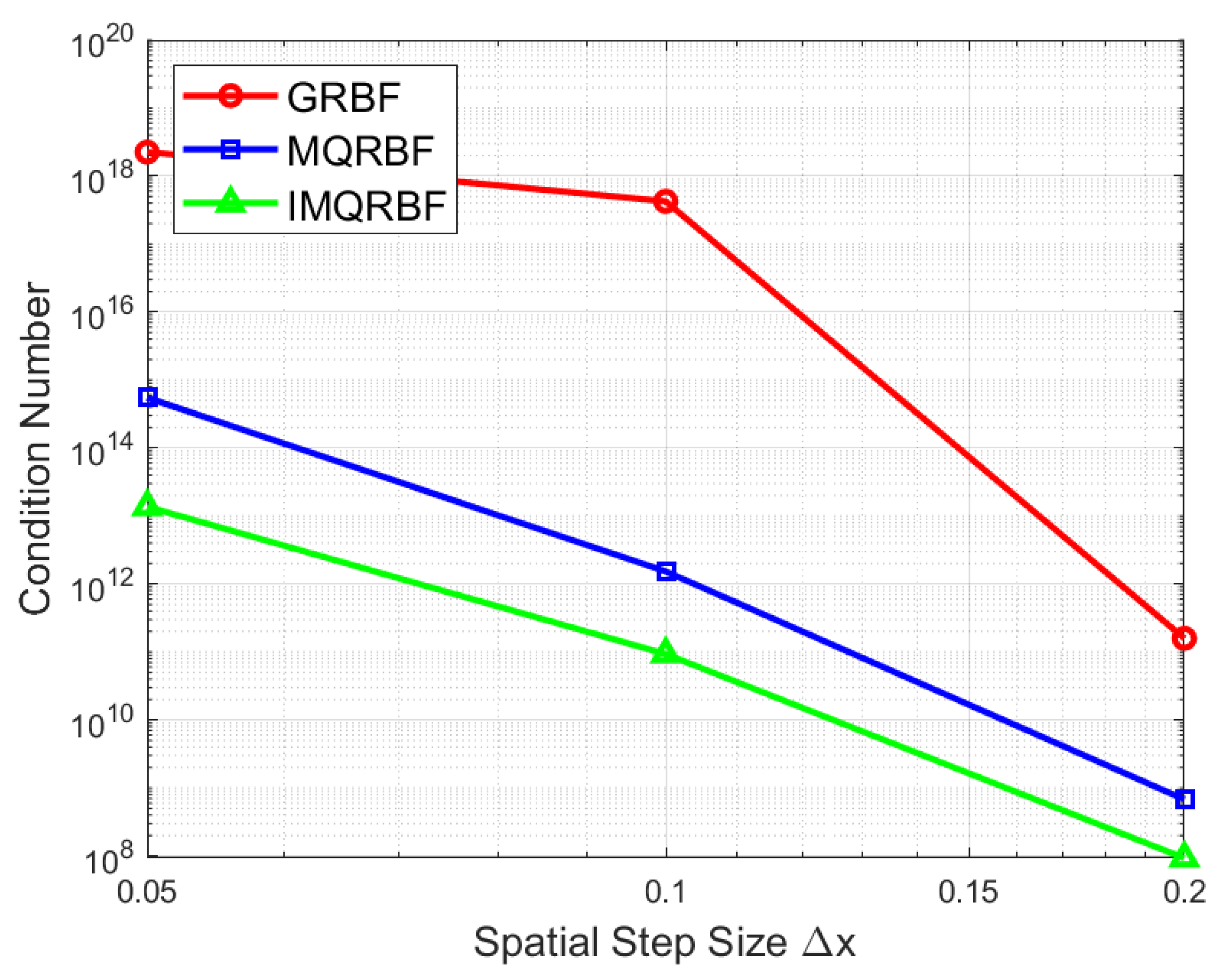
Table 10 and Figure 27 show the condition numbers k of the collocation matrix corresponding to the GRBF, MQRBF, and IMQRBFs for spatial step sizes Δ x = 1 / 5 , 1 / 10 , 1 / 20 .
The condition numbers increase rapidly as the spatial resolution is refined. GRBF exhibits the most severe growth in ill-conditioning—by more than seven orders of magnitude between Δ x = 1 5 and Δ x = 1 20 . Although the MQRBF and IMQRBF also experience increases, the rate is significantly lower, particularly for IMQRBF. These results confirm that IMQRBF offers the best numerical stability across grid refinements, while GRBF becomes impractical without preconditioning or regularization at finer meshes.
Overall, IMQRBF is the most reliable RBF choice for inverse parabolic problems when shape parameter optimization is challenging or computationally constrained. And Table 11 summarizes the results.

4. Discussion

The numerical results in Section 3 validate the effectiveness of the RBF collocation method for inverse parabolic problems using two test cases with known analytical solutions. All three RBF types—GRBF, MQRBF, and IMQRBF—were evaluated in terms of accuracy, stability, and sensitivity to the shape parameter.
For both problems, MQRBF and IMQRBF consistently outperformed GRBF, particularly at finer spatial resolutions. While MQRBF provided the highest overall accuracy, IMQRBF demonstrated superior stability and smoother error profiles, especially when Δ x = 1 / 20 . These outcomes can be attributed to their respective functional structures: MQRBF balances flexibility with numerical robustness, whereas IMQRBF’s decay characteristics enhance conditioning.
The shape parameter c plays a central role in performance. As shown in Table 6, Table 7 and Table 8, optimal choices vary by RBF type—typically c = 1 for GRBF, and c = 2 to 2.5 for MQRBF and IMQRBF. Deviating from these optimal values leads to significant degradation in accuracy or matrix conditioning.
Condition number analysis further confirmed the limitations of GRBF, which suffers from rapid ill-conditioning under grid refinement. In contrast, MQRBF and IMQRBF maintained lower condition numbers across spatial step sizes, reinforcing their suitability for inverse problems where stability is crucial.
Overall, the results emphasize the need for careful selection of RBF type and shape parameter to ensure accuracy and stability in practical implementations.

5. Conclusions

This study presented a comparative evaluation of three radial basis functions—GRBF, MQRBF, and IMQRBF—for solving one-dimensional inverse parabolic problems with overspecified energy conditions. A transformation to an equivalent direct problem enabled the use of an RBF-based collocation method in both space and time.
The numerical experiments demonstrated that MQRBF and IMQRBF offer superior accuracy and stability compared to GRBF, with MQRBF generally achieving the lowest error norms and IMQRBF exhibiting the most stable performance under mesh refinement. The influence of the shape parameter was systematically investigated, and condition number analysis highlighted the trade-off between accuracy and numerical stability.
These findings offer practical guidance for applying RBF methods to inverse problems and address key gaps in the literature by comparing multiple RBF types, analyzing parameter sensitivity, and evaluating matrix conditioning.
Although the study used test problems with known solutions for validation, many real-world inverse problems involve partial or noisy observations and lack analytic expressions. Extending this framework to handle such scenarios remains a critical direction for future research.
Potential avenues include adaptive shape parameter strategies, extensions to multi-dimensional problems, and robustness testing under noisy data. While higher-dimensional applications are feasible, they introduce challenges such as increased computational cost, severe ill-conditioning, and complex domain handling. Nonetheless, prior work—e.g., Ma and Wu [9]—demonstrates the scalability of RBF-based approaches when combined with suitable stabilization and implementation techniques. Continued exploration of these aspects will support the broader applicability of RBF collocation methods to real-world inverse problems.

Author Contributions

Conceptualization, U.P.; methodology, U.P. and S.W.; software, U.P. and S.W.; validation, U.P. and S.W.; formal analysis, U.P. and S.W.; investigation, U.P. and S.W.; resources, U.P. and S.W.; data curation, U.P. and S.W.; writing—original draft preparation, S.W.; writing—review and editing, U.P.; visualization, U.P. and S.W.; supervision, U.P.; project administration, U.P. All authors have read and agreed to the published version of the manuscript.

Funding

This research received no external funding.

Data Availability Statement

The MATLAB code and numerical data used to generate the results in this study are publicly available at the following GitHub repository: https://github.com/upeksha1/RBF (accessed on 21 August 2025).

Conflicts of Interest

The authors declare no conflicts of interest.

Abbreviations

The following abbreviations are used in this manuscript:
RBFRadial Basis Function
GRBFGaussian Radial Basis Function
MQRBFMultiquadrics Radial Basis Function
IMQRBFInverse Multiquadrics Radial Basis Function
PDEPartial Differential Equation

References

  1. Orlande, H.R.B. Inverse Heat Transfer: Fundamentals and Applications, 2nd ed.; CRC Press: Boca Raton, FL, USA, 2021. [Google Scholar] [CrossRef]
  2. Cannon, J. The One-Dimensional Heat Equation; Encyclopedia of Mathematics and its Applications; Cambridge University Press: Cambridge, UK, 1984. [Google Scholar]
  3. Tatari, M.; Dehghan, M. He’s variational iteration method for computing a control parameter in a semi-linear inverse parabolic equation. Chaos Solitons Fractals 2007, 33, 671–677. [Google Scholar] [CrossRef]
  4. Liu, Z.; Tatar, S. Analytical solutions of a class of inverse coefficient problems. Appl. Math. Lett. 2012, 25, 2391–2395. [Google Scholar] [CrossRef]
  5. Cannon, J.; Lin, Y. An inverse problem of finding a parameter in a semi-linear heat equation. J. Math. Anal. Appl. 1990, 145, 470–484. [Google Scholar] [CrossRef]
  6. Cannon, J.; Lin, Y.; Wang, S. Determination of a control parameter in a parabolic partial differential equation. ANZIAM J. 1991, 33, 149–163. [Google Scholar] [CrossRef]
  7. Abbasbandy, S.; Hajishafieiha, J. A numerical method for an inverse problem concerning the two-dimensional diffusion equation with source control parameter by new polynomials. Sigma 2023, 41, 469–480. [Google Scholar]
  8. Dehghan, M.; Tatari, M. Determination of a control parameter in a one-dimensional parabolic equation using the method of radial basis functions. Math. Comput. Model. 2006, 44, 1160–1168. [Google Scholar] [CrossRef]
  9. Ma, L.; Wu, Z. Radial basis functions method for parabolic inverse problem. Int. J. Comput. Math. 2011, 88, 384–395. [Google Scholar] [CrossRef]
  10. Ranjbar, M.; Aghazadeh, M. Collocation method based on shifted Chebyshev and radial basis functions with symmetric variable shape parameter for solving the parabolic inverse problem. Inverse Probl. Sci. Eng. 2019, 27, 369–387. [Google Scholar] [CrossRef]
Figure 1. Radial basis functions (RBFs) plotted with shape parameter c = 1 . Gaussian, multiquadric, and inverse multiquadric RBFs exhibit different decay and smoothness behaviors. Polynomial-based functions like cubic and thin plate spline do not depend on c. The choice of RBF affects interpolation accuracy and numerical stability.
Algorithms 18 00539 g001
Figure 2. Space–time grid illustrating the application of conditions in the RBF collocation method. The red edges denote boundary conditions, the bottom edge represents the initial condition, and the green dot marks the interior point x * where the energy measurement is specified.
Algorithms 18 00539 g002
Figure 3. (a) Exact vs approximated source function p ( t ) , and (b) absolute error | p ( t ) p ˜ ( t ) | using GRBF with Δ x = 1 / 5 and c = 10 Δ x . The initial error is high and increases linearly with t, indicating acceptable convergence behavior.
Algorithms 18 00539 g003
Figure 4. (a) Exact and approximated source function p ( t ) , and (b) absolute error | p ( t ) p ˜ ( t ) | using the GRBF with refined grid ( Δ x = 1 / 10 ) and shape parameter c = 10 Δ x . The error magnitude is reduced compared to coarser discretization (Figure 3), demonstrating the benefit of mesh refinement for accuracy.
Algorithms 18 00539 g004
Figure 5. (a) Exact and approximated source function p ( t ) , and (b) absolute error | p ( t ) p ˜ ( t ) | for Test Problem 1 using the GRBF with step size Δ x = 1 20 and shape parameter c = 10 Δ x . The error remains small throughout the interval, with a generally increasing trend.
Algorithms 18 00539 g005
Figure 6. (a) Comparison of the exact and approximated source function p ( t ) and (b) the absolute error | p ( t ) p ˜ ( t ) | for Test Problem 1 using the MQRBF. Results are computed with step size Δ x = 1 / 5 and shape parameter c = 10 Δ x . The MQRBF yields lower error than the GRBF (Figure 3), with stable performance across the time interval.
Algorithms 18 00539 g006
Figure 7. (a) Exact and approximated source function p ( t ) and (b) the absolute error | p ( t ) p ˜ ( t ) | using MQRBF for Δ x = 1 / 10 and shape parameter c = 10 Δ x . The error decreases significantly compared to coarser grids, confirming improved resolution and accuracy with finer discretization.
Algorithms 18 00539 g007
Figure 8. (a) Approximated source function p ( t ) and (b) the absolute error | p ( t ) p ˜ ( t ) | using the MQRBF with fine resolution Δ x = 1 / 20 and shape parameter c = 10 Δ x . The results show excellent agreement with the exact solution and minimal error, indicating strong stability and convergence of the MQRBF at fine scales.
Algorithms 18 00539 g008
Figure 9. (a) Comparison of the exact and approximated source function p ( t ) and (b) the absolute error | p ( t ) p ˜ ( t ) | for Test Problem 1 using the IMQRBF with Δ x = 1 / 5 and shape parameter c = 10 Δ x . The IMQRBF produces accurate results with reasonable error levels across the time interval.
Algorithms 18 00539 g009
Figure 10. (a) Exact and approximated source function p ( t ) and (b) the absolute error | p ( t ) p ˜ ( t ) | using the IMQRBF with Δ x = 1 / 10 and c = 10 Δ x . The results exhibit improved accuracy compared to coarser grids.
Algorithms 18 00539 g010
Figure 11. (a) Approximation of the source function p ( t ) and (b) absolute error | p ( t ) p ˜ ( t ) | using the IMQRBF for Δ x = 1 / 20 and c = 10 Δ x . The numerical solution shows strong convergence toward the exact solution, with error remaining small.
Algorithms 18 00539 g011
Figure 12. (a) Comparison of the approximated source function p ˜ ( t ) and (b) absolute error | p ( t ) p ˜ ( t ) | using GRBF, MQRBF, and IMQRBF with Δ x = 1 / 5 and c = 10 Δ x . MQRBF yields the lowest error, demonstrating strong performance at coarse resolution.
Algorithms 18 00539 g012
Figure 13. (a) Approximated source function p ˜ ( t ) and (b) absolute error | p ( t ) p ˜ ( t ) | for Test Problem 1 using three different RBFs with Δ x = 1 / 10 and c = 10 Δ x . MQRBF outperforms others, providing the most stable and accurate results.
Algorithms 18 00539 g013
Figure 14. (a) Approximated source function p ˜ ( t ) and (b) absolute error | p ( t ) p ˜ ( t ) | with resolution Δ x = 1 / 20 . MQRBF consistently produces the smallest errors, confirming its effectiveness for high-resolution computations.
Algorithms 18 00539 g014
Figure 15. Approximation error | ω ( x , t ) ω ˜ ( x , t ) | using (a) GRBF, (b) MQRBF, and (c) IMQRBF for Test Problem 1 with spatial step size Δ x = 1 / 5 and shape parameter c = 10 Δ x . Among the three, MQRBF yields the lowest error across the domain, showing its robustness at moderate resolution.
Algorithms 18 00539 g015
Figure 16. Approximation error | ω ( x , t ) ω ˜ ( x , t ) | for Test Problem 1 using (a) GRBF, (b) MQRBF, and (c) IMQRBF with spatial step size Δ x = 1 10 . The GRBF yields relatively small but fluctuating errors across the domain, while the MQRBF achieves smoother and more stable performance.
Algorithms 18 00539 g016
Figure 17. Absolute error | ω ( x , t ) ω ˜ ( x , t ) | computed using (a) GRBF, (b) MQRBF, and (c) IMQRBF for Test Problem 1 at high resolution ( Δ x = 1 / 20 ) with shape parameter c = 10 Δ x . MQRBF yields the most accurate and smoothest error profile, confirming its superior performance for finely discretized inverse parabolic problems.
Algorithms 18 00539 g017
Figure 18. Comparison of GRBF, MQRBF, and IMQRBF radial basis functions for different shape parameters (a) c = 0.5 , (b) c = 1.0 , and (c) c = 2.0 .
Algorithms 18 00539 g018
Figure 19. (a) Comparison of the approximated source function p ˜ ( t ) and (b) the absolute error | p ( t ) p ˜ ( t ) | for Test Problem 2 using GRBF, MQRBF and IMQRBF at coarse resolution Δ x = 1 / 5 with shape parameter c = 10 Δ x . MQRBF performs better at this resolution.
Algorithms 18 00539 g019
Figure 20. (a) Approximated source function p ˜ ( t ) and (b) absolute error | p ( t ) p ˜ ( t ) | for Test Problem 2 using the three RBFs at medium resolution Δ x = 1 / 10 . The IMQRBF shows the lowest overall error, demonstrating its increased accuracy and robustness at finer discretization levels.
Algorithms 18 00539 g020
Figure 21. (a) Comparison of source control parameter approximation p ˜ ( t ) and (b) the absolute error | p ( t ) p ˜ ( t ) | for Test Problem 2 using GRBF, MQRBF, and IMQRBF with fine resolution Δ x = 1 / 20 . IMQRBF provides the most accurate and stable approximation, exhibiting significantly reduced error across the entire time domain.
Algorithms 18 00539 g021
Figure 22. Absolute error | ω ( x , t ) ω ˜ ( x , t ) | for Test Problem 2 using (a) GRBF, (b) MQRBF, and (c) IMQRBF at coarse resolution Δ x = 1 / 5 and shape parameter c = 10 Δ x . All three methods yield similar error magnitudes, with MQRBF slightly outperforming the others near the boundaries.
Algorithms 18 00539 g022
Figure 23. Error in the numerical solution ω ˜ ( x , t ) for Test Problem 2 using (a) GRBF, (b) MQRBF, and (c) IMQRBF at Δ x = 1 10 . Although GRBF yields the lowest error magnitudes, its strong fluctuations reduce reliability. MQRBF and IMQRBF offer smoother, more stable errors, with IMQRBF showing the most consistent performance in the interior region.
Algorithms 18 00539 g023
Figure 24. Error in the numerical solution ω ˜ ( x , t ) for Test Problem 2 using (a) GRBF, (b) MQRBF, and (c) IMQRBF at Δ x = 1 20 . The results show similar behavior to the Δ x = 1 10 case: although GRBF yields the lowest error magnitudes, its strong fluctuations reduce reliability. MQRBF and IMQRBF provide smoother, more stable errors, with MQRBF maintaining the most consistent accuracy in the interior region.
Algorithms 18 00539 g024
Figure 25. Comparison of shape parameter sensitivity for GRBF, MQRBF, and IMQRBF. Each panel shows the variation in the maximum error E and L 2 error E 2 with shape parameter c for three spatial resolutions. GRBF performs best near c = 1 , while both MQRBF and IMQRBF achieve optimal accuracy and stability around c = 2 , with IMQRBF showing the most robust behavior across resolutions.
Algorithms 18 00539 g025
Figure 26. CPU time vs. Δ x for three RBF methods applied to (a) Problem 1 and (b) Problem 2.
Algorithms 18 00539 g026
Figure 27. Log–log plot of the condition number of the collocation matrix versus the spatial step size Δ x for GRBF, MQRBF, and IMQRBF. As the resolution increases (i.e., Δ x decreases), the condition number grows significantly—most severely for the GRBF. The IMQRBF exhibits the slowest growth in ill-conditioning, indicating superior numerical stability.
Algorithms 18 00539 g027
Table 1. Some common choices for RBFs.
Function NameMathematical Definition
Cubic ϕ ( r ) = r 3
Gaussian (GRBF) ϕ ( r ) = exp ( r 2 / 2 c 2 ) , c > 0
Hardy Multiquadric (MQRBF) ϕ ( r ) = r 2 + c 2
Inverse Multiquadric (IMQRBF) ϕ ( r ) = ( r 2 + c 2 ) 1
Inverse Quadratic (IQ) ϕ ( r ) = ( r 2 + c 2 ) 1
Thin plate spline ϕ ( r ) = r 2 ln ( r )
Table 2. Description of subregions and applied conditions in the RBF collocation method.
RegionCondition AppliedDescription
Ω 1 u ( x , 0 ) = f ( x ) Initial condition for all x at t = 0
Ω 2 u ( 0 , t ) = r ( t ) g 0 ( t ) Left boundary condition at x = 0 , t > 0
Ω 3 u ( 1 , t ) = r ( t ) g 1 ( t ) Right boundary condition at x = 1 , t > 0
Ω 4 u t = u x x + r ( t ) φ ( x , t ) Governing PDE applied in the interior domain
x * ( 0 , 1 ) u ( x * , t ) = r ( t ) E ( t ) Energy overspecification condition at internal point x *
Table 3. Maximum error norm E and E 2 error norm for the approximation of ω ( x , t ) using GRBF with shape parameter values c = 0.2 , 0.5 , 1 , 1.5 , 2 , 2.5 , 3 , 3.5 , 4 , 5 and spatial step sizes Δ x = 1 5 , 1 10 , 1 20 . The lowest error for GRBF occurs near c = 1 , but stability deteriorates for both smaller and larger c, especially at fine resolution. (The minimum error for each column is highlighted in bold).
Shape Parameter 1 5 1 10 1 20
E Error E 2 Error E Error E 2 Error E Error E 2 Error
0.2 7.48 × 10 2 1.27 × 10 0 4.96 × 10 3 2.22 × 10 1 1.51 × 10 6 2.93 × 10 5
0.5 1.40 × 10 3 3.34 × 10 2 3 . 57 × 10 6 1.92 × 10 4 4 . 56 × 10 7 2 . 71 × 10 5
1.0 1 . 00 × 10 4 2 . 60 × 10 3 4.90 × 10 6 8 . 59 × 10 5 5.03 × 10 3 6.89 × 10 2
1.5 8.00 × 10 4 1.52 × 10 2 2.93 × 10 1 2.56 × 10 2 1.42 × 10 2 3.09 × 10 1
2.0 1.10 × 10 3 2.29 × 10 2 1.22 × 10 1 0.51 × 10 2 1.71 × 10 3 2.46 × 10 3
2.5 1.20 × 10 3 2.69 × 10 2 2.86 × 10 1 1.62 × 10 2 2.77 × 10 1 1.64 × 10 2
3.0 1.30 × 10 3 2.92 × 10 2 1.09 × 10 2 3.58 × 10 2 7.33 × 10 2 3.91 × 10 0
3.5 1.36 × 10 3 3.06 × 10 2 2.63 × 10 1 1.41 × 10 2 5.10 × 10 1 1.89 × 10 2
4.0 1.40 × 10 3 3.14 × 10 2 6.76 × 10 1 3.07 × 10 2 8.20 × 10 0 6.05 × 10 1
5.0 1.56 × 10 3 3.29 × 10 2 1.75 × 10 2 4.71 × 10 2 1.58 × 10 1 3.19 × 10 2
Table 4. Maximum error norm E and E 2 error norm for the approximation of ω ( x , t ) using MQRBF with shape parameter values c = 0.2 , 0.5 , 1 , 1.5 , 2 , 2.5 , 3 , 3.5 , 4 , 5 and spatial step sizes Δ x = 1 5 , 1 10 , 1 20 . For the MQRBF, the lowest errors occur near shape parameter c = 2 , particularly for the medium resolution Δ x = 1 10 . The method shows good numerical performance over a broader range of c values compared to GRBF. (The minimum error for each column is highlighted in bold).
Shape Parameter 1 5 1 10 1 20
E Error E 2 Error E Error E 2 Error E Error E 2 Error
0.2 2.67 × 10 2 6.02 × 10 1 8.01 × 10 3 3.36 × 10 1 1.07 × 10 3 1.06 × 10 1
0.5 1.45 × 10 2 3.44 × 10 1 1.41 × 10 3 8.64 × 10 2 1 . 78 × 10 5 2.74 × 10 3
1.0 6.93 × 10 3 1.20 × 10 1 8.20 × 10 5 3.73 × 10 3 2.79 × 10 5 8 . 46 × 10 4
1.5 2.23 × 10 3 3.87 × 10 2 4.74 × 10 6 3.14 × 10 4 5.45 × 10 2 1.87 × 10 3
2.0 6.23 × 10 4 1.48 × 10 2 1 . 78 × 10 6 9 . 30 × 10 5 6.81 × 10 1 6.60 × 10 2
2.5 4 . 01 × 10 4 9 . 54 × 10 3 3.73 × 10 5 6.54 × 10 4 7.58 × 10 5 3.47 × 10 3
3.0 7.89 × 10 4 1.31 × 10 2 8.13 × 10 4 1.55 × 10 2 8.18 × 10 1 6.11 × 10 2
3.5 1.01 × 10 3 1.72 × 10 2 2.27 × 10 4 4.61 × 10 3 1.42 × 10 1 1.09 × 10 2
4.0 1.14 × 10 3 2.06 × 10 2 2.21 × 10 4 4.84 × 10 3 2.39 × 10 3 8.54 × 10 2
5.0 1.28 × 10 3 2.51 × 10 2 3.05 × 10 3 5.42 × 10 2 2.01 × 10 2 4.86 × 10 2
Table 5. Maximum error norm E and E 2 error norm for the approximation of ω ( x , t ) using IMQRBF for shape parameter values c = 0.2 , 0.5 , 1 , 1.5 , 2 , 2.5 , 3 , 3.5 , 4 , 5 and spatial step sizes Δ x = 1 5 , 1 10 , 1 20 . The IMQRBF demonstrates strong numerical stability across all tested shape parameters and resolutions. Optimal performance is consistently achieved near c = 2.5 . (The minimum error for each column is highlighted in bold).
Shape Parameter 1 5 1 10 1 20
E Error E 2 Error E Error E 2 Error E Error E 2 Error
0.2 8.34 × 10 2 1.37 × 10 0 3.58 × 10 2 1.51 × 10 0 5.22 × 10 3 6.22 × 10 1
0.5 1.31 × 10 2 3.11 × 10 1 2.29 × 10 3 9.79 × 10 2 4.57 × 10 5 4.51 × 10 3
1.0 5.16 × 10 3 1.28 × 10 1 1.68 × 10 4 9.43 × 10 3 3.41 × 10 5 1.23 × 10 3
1.5 3.09 × 10 3 5.21 × 10 2 6.51 × 10 6 2.92 × 10 4 2.83 × 10 3 7.38 × 10 2
2.0 1.25 × 10 3 2.30 × 10 2 1.85 × 10 6 1.23 × 10 4 1.84 × 10 2 9.05 × 10 2
2.5 4.49 × 10 4 1.05 × 10 2 1 . 09 × 10 6 4 . 35 × 10 5 1 . 79 × 10 5 8 . 72 × 10 4
3.0 3 . 10 × 10 4 7 . 10 × 10 3 8.83 × 10 1 3.03 × 10 2 2.39 × 10 1 3.23 × 10 2
3.5 6.40 × 10 4 1.06 × 10 2 2.94 × 10 1 8.59 × 10 1 3.26 × 10 1 4.00 × 10 2
4.0 8.51 × 10 4 1.47 × 10 2 1.19 × 10 4 2.18 × 10 3 3.02 × 10 4 1.23 × 10 2
5.0 1.09 × 10 3 2.08 × 10 2 1.37 × 10 4 3.49 × 10 3 1.34 × 10 2 3.43 × 10 1
Table 6. Maximum error norm E and E 2 error norm using GRBF for Test problem 2. The lowest error for GRBF occurs near c = 1 , but stability deteriorates for both smaller and larger c, especially at fine resolution. (The minimum error for each column is highlighted in bold).
Shape ParameterΔx = 1 5 Δx = 1 10 Δx = 1 20
E Error E 2 Error E Error E 2 Error E Error E 2 Error
0.2 5.7 × 10 3 9.94 × 10 2 5.4 × 10 4 2.3 × 10 2 1.69 × 10 4 2.76 × 10 4
0.5 1.9 × 10 4 2.80 × 10 3 7.8 × 10 8 3.5 × 10 6 6.26 × 10 1 3.41 × 10 2
1.0 5 . 9 × 10 5 9 . 00 × 10 4 5 . 3 × 10 8 1 . 4 × 10 6 4 . 67 × 10 7 3 . 23 × 10 5
1.5 1.7 × 10 4 2.50 × 10 3 3.5 × 10 0 4.0 × 10 1 2.95 × 10 3 1.78 × 10 1
2.0 2.2 × 10 4 3.20 × 10 3 6.8 × 10 0 2.8 × 10 1 4.48 × 10 3 2.50 × 10 1
2.5 2.5 × 10 4 3.70 × 10 3 1.3 × 10 0 1.0 × 10 1 2.32 × 10 1 8.72 × 10 1
3.0 2.6 × 10 4 3.90 × 10 3 8.0 × 10 0 2.9 × 10 1 6.61 × 10 0 4.29 × 10 1
3.5 2.7 × 10 4 4.05 × 10 3 1.7 × 10 0 6.7 × 10 0 3.74 × 10 0 3.10 × 10 1
4.0 2.8 × 10 4 4.14 × 10 3 1.3 × 10 0 5.2 × 10 0 7.20 × 10 0 4.98 × 10 1
5.0 2.8 × 10 4 4.22 × 10 3 1.6 × 10 1 4.3 × 10 1 2.15 × 10 0 4.01 × 10 1
Table 7. Maximum error norm E and E 2 error norm using MQRBF for shape parameter values c = 0.2 , 0.5 , 1 , 1.5 , 2 , 2.5 , 3 , 3.5 , 4 , 5 and Δ x = 1 5 , 1 10 , 1 20 . The lowest error for occurs near c = 2 . (The minimum error for each column is highlighted in bold).
Shape ParameterΔx = 1 5 Δx = 1 10 Δx = 1 20
E Error E 2 Error E Error E 2 Error E Error E 2 Error
0.2 5.18 × 10 3 7.79 × 10 2 1.33 × 10 3 4.75 × 10 2 1.44 × 10 4 1.38 × 10 2
0.5 7.42 × 10 4 1.11 × 10 2 4.26 × 10 5 1.59 × 10 3 1 . 65 × 10 7 1 . 55 × 10 5
1.0 2.23 × 10 4 3.24 × 10 3 4.68 × 10 6 1.68 × 10 4 3.61 × 10 1 1.19 × 10 2
1.5 1.65 × 10 4 2.44 × 10 3 2.30 × 10 7 9.34 × 10 6 1.00 × 10 1 1.41 × 10 2
2.0 4 . 01 × 10 5 6 . 03 × 10 4 6 . 03 × 10 8 2.02 × 10 6 4.71 × 10 4 1.84 × 10 2
2.5 5.23 × 10 5 7.75 × 10 4 5.29 × 10 7 2 . 01 × 10 6 2.56 × 10 0 4.33 × 10 1
3.0 1.15 × 10 4 1.71 × 10 3 8.72 × 10 6 1.79 × 10 4 3.76 × 10 1 2.02 × 10 0
3.5 1.57 × 10 4 2.35 × 10 3 9.48 × 10 6 2.70 × 10 4 1.06 × 10 1 4.71 × 10 1
4.0 1.87 × 10 4 2.80 × 10 3 1.37 × 10 4 2.19 × 10 3 1.33 × 10 4 8.96 × 10 3
5.0 2.24 × 10 4 3.36 × 10 3 2.66 × 10 4 5.74 × 10 3 9.38 × 10 1 2.03 × 10 1
Table 8. Maximum error norm E and E 2 error norm using IMQRBF for shape parameter values c = 0.2 , 0.5 , 1 , 1.5 , 2 , 2.5 , 3 , 3.5 , 4 , 5 and Δ x = 1 5 , 1 10 , 1 20 . The lowest error for IMQRBF occurs near c = 2 . (The minimum error for each column is highlighted in bold).
Shape ParameterΔx = 1 5 Δx = 1 10 Δx = 1 20
E Error E 2 Error E Error E 2 Error E Error E 2 Error
0.2 8.76 × 10 3 1.38 × 10 1 3.61 × 10 3 1.28 × 10 1 5.70 × 10 4 5.46 × 10 2
0.5 3.10 × 10 3 4.43 × 10 2 3.96 × 10 4 1.38 × 10 2 5.75 × 10 6 5.41 × 10 4
1.0 2.90 × 10 4 4.30 × 10 3 1.26 × 10 6 4.64 × 10 5 2.73 × 10 0 7.37 × 10 2
1.5 1.04 × 10 4 1.50 × 10 3 5.66 × 10 7 2.20 × 10 5 4.35 × 10 8 2.83 × 10 6
2.0 8.10 × 10 5 1.19 × 10 3 8 . 93 × 10 9 3 . 38 × 10 7 2 . 39 × 10 8 1 . 46 × 10 6
2.5 5 . 83 × 10 6 1 . 13 × 10 4 6.98 × 10 8 2.19 × 10 6 7.71 × 10 8 6.05 × 10 6
3.0 6.00 × 10 5 8.80 × 10 4 2.69 × 10 1 1.81 × 10 2 8.56 × 10 1 2.22 × 10 1
3.5 1.10 × 10 4 1.63 × 10 3 2.10 × 10 0 1.33 × 10 1 2.50 × 10 0 5.15 × 10 1
4.0 1.47 × 10 4 2.18 × 10 3 9.24 × 10 6 2.23 × 10 4 3.76 × 10 5 2.17 × 10 3
5.0 1.96 × 10 4 2.92 × 10 3 5.63 × 10 5 1.49 × 10 3 2.04 × 10 3 4.11 × 10 2
Table 9. Measured CPU time (in seconds) for each RBF method, test problem, and spatial step size Δ x .
RBFProblemΔx = 0.1 0.20.30.40.50.60.70.80.9
GRBFProblem 10.01230.00130.00090.00090.00070.00050.00050.00050.0005
Problem 20.00520.00130.00090.00120.00060.00060.00060.00060.0005
MQRBFProblem 10.00440.00140.00080.00090.00060.00070.00050.00050.0005
Problem 20.00340.00140.00090.00090.00070.00080.00060.00060.0006
IMQRBFProblem 10.00470.00140.00080.00080.00060.00060.00050.00050.0006
Problem 20.00320.00140.00090.00090.00070.00070.00070.00060.0006
Table 10. Condition numbers of the collocation matrix for different RBFs at spatial step sizes Δ x = 1 5 , 1 10 , 1 20 . The final column shows the relative increase in condition number between Δ x = 1 5 and Δ x = 1 20 .
RBFΔx = 1 5 Δx = 1 10 Δx = 1 20 Relative Increase
GRBF 1.59 × 10 11 4.24 × 10 17 2.25 × 10 18 1.42 × 10 7
MQRBF 6.78 × 10 8 1.53 × 10 12 5.49 × 10 14 8.11 × 10 5
IMQRBF 9.28 × 10 7 9.31 × 10 10 1.37 × 10 13 1.47 × 10 5
Table 11. Comparison of RBF types across different spatial resolutions for both test problems. Optimal shape parameters are based on lowest E error.
RBF TypeOptimal cBest ResolutionStability (Condition Number)Performance Rank
GRBF1.0 Δ x = 1 / 5 Poor at fine gridModerate
MQRBF2.0 Δ x = 1 / 10 ModerateGood
IMQRBF2.0 Δ x = 1 / 20 ExcellentBest
Disclaimer/Publisher’s Note: The statements, opinions and data contained in all publications are solely those of the individual author(s) and contributor(s) and not of MDPI and/or the editor(s). MDPI and/or the editor(s) disclaim responsibility for any injury to people or property resulting from any ideas, methods, instructions or products referred to in the content.