Article

Hierarchical Coordination Control of Distributed Drive Intelligent Vehicle Based on TSMPC and Tire Force Optimization Allocation

1
School of Mechanical and Aeronautical Manufacturing Engineering, Anyang Institute of Technology, Anyang 455000, China
2
Henan Zhenghang Spindle Technology Company Limited, Anyang 455000, China
3
Automotive Engineering Research Institute, Jiangsu University, Zhenjiang 212013, China
*
Author to whom correspondence should be addressed.
Algorithms 2025, 18(8), 508; https://doi.org/10.3390/a18080508
Submission received: 8 July 2025 / Revised: 4 August 2025 / Accepted: 11 August 2025 / Published: 13 August 2025
(This article belongs to the Section Parallel and Distributed Algorithms)

Abstract

An intelligent vehicle hierarchical coordinated control strategy based on time delay state feedback model predictive control (TSMPC) and tire force optimization allocation is presented. Aiming at the problem of insufficient trajectory tracking accuracy and the limited time delay compensation capability of distributed drive intelligent vehicles in complex working conditions, an innovative hierarchical control architecture was designed by establishing vehicle dynamics models and path tracking models. The upper-level controller adopts TSMPC algorithm, which significantly improves the coordinated control ability of path tracking and vehicle stability through incremental prediction model and time–delay state feedback mechanism. The lower-level controller adopts an improved artificial bee colony (IABC) algorithm to optimize tire force allocation, effectively solving the dynamic performance optimization problem of redundant drive systems. Simulation verification shows that compared with traditional model predictive control (MPC) algorithms, TSMPC algorithm exhibits significant advantages in trajectory accurateness, error suppression, and stability control. In addition, the IABC algorithm further improves the trajectory accurateness and stability control performance of vehicles in tire force optimization allocation.

1. Introduction

As transportation demands continue to rise alongside growing societal emphasis on travel efficiency and safety, intelligent vehicle technology has emerged as a pivotal innovation in modern transportation systems. Trajectory tracking control, a core component of this technology, enables critical autonomous driving functions, including path following, platooning, and precise maneuverability in complex road scenarios [1,2]. This capability ensures reliable adherence to predefined trajectories across diverse driving conditions, offering significant benefits such as enhanced road safety, optimized traffic flow efficiency, and the accelerated development of intelligent transportation infrastructure [3,4].
Among various vehicle chassis technologies, the distributed drive chassis provides new ideas and opportunities for the research of intelligent vehicle trajectory tracking control due to its unique structural advantages [5,6]. The distributed drive chassis achieves independent distribution and the precise control of driving force by installing multiple motors on the wheels, which makes the vehicle more flexible and adaptable in terms of power output, steering performance, and response speed [7,8,9]. Compared with traditional centralized drive chassis, distributed drive chassis can better meet the high requirements of intelligent vehicles for trajectory tracking accuracy and dynamic performance in complex working conditions. Therefore, combining intelligent vehicle trajectory tracking control with distributed drive chassis can better leverage the advantages of both and achieve the comprehensive optimization of vehicle control objectives, which has important theoretical research value and broad application prospects [10,11,12].
The performance of vehicle path tracking, particularly its accurateness and stability, plays a crucial role in ensuring driving safety and passenger comfort. Conventional control methods often face challenges in maintaining both high-precision trajectory tracking and vehicle stability, especially under complex driving conditions [13,14,15,16]. MPC has emerged as an effective solution, leveraging its superior dynamic response and constraint-handling capabilities to address these limitations. Due to its ability to optimize multiple variables while flexibly managing system constraints, MPC has become a prominent research focus in intelligent vehicle trajectory tracking. Furthermore, advancements in autonomous driving technology have spurred continuous improvements in MPC-based control strategies, expanding their applicability and effectiveness in real-world scenarios [17,18,19]. On the one hand, MPC can adjust the control input in advance by predicting the system state in the future, so as to effectively cope with complex road conditions and dynamic driving environment. This prediction-based control strategy enables vehicles to better balance stability and accuracy during trajectory tracking. On the other hand, MPC exhibits unique advantages in dealing with the nonlinear characteristics of vehicle dynamics models, especially in adaptive research in low-speed and high-speed scenarios. By reasonably simplifying the model and optimizing algorithms, it can alleviate the contradiction between computational complexity and real-time performance to a certain extent [20,21,22].
However, although MPC has made significant progress in intelligent vehicle trajectory tracking control, it still faces many challenges in practical applications. Especially when facing complex vehicle dynamics, the performance and efficiency of MPC are constrained by various factors [23,24]. Among them, MPC still has certain limitations when dealing with time delay systems and multi-constraint optimization problems. Intelligent vehicle trajectory tracking control requires the prediction and optimization calculation of vehicle status to be completed in a short period of time. However, complex vehicle dynamics models often contain a large number of nonlinear factors and multivariate constraints, which makes the online optimization calculation of MPC extremely complex [25,26]. In order to meet real-time requirements, for researchers, a critical challenge lies in achieving an optimal trade-off between the representational ability of models and the optimization solving ability of algorithms. Overly simplified models may lead to insufficient control accuracy, while overly complex models may result in long computation times that cannot meet the requirements of real-time control [27,28,29]. When faced with inherent time delays in vehicle dynamics systems, such as sensor measurement lag, communication delay, and actuator response delay, traditional MPC often exhibits two shortcomings: firstly, delays disrupt the temporal consistency between prediction models and actual systems, leading to the premature “expiration” of optimized sequences, resulting in significant tracking lag and overshoot under transient conditions such as rapid lane changing or emergency obstacle avoidance. Secondly, in order to alleviate the mismatch caused by delay, the conventional approach is to compress the prediction time domain online or simplify the model order [30,31]. However, this sacrifices the original optimization degrees of freedom of MPC in multi-constraint coordination (such as tire adhesion limit, actuator saturation, and roll safety boundary), resulting in a sharp reduction in the feasible solution space, and even no feasible solution due to constraint conflicts.
In addition, trajectory tracking control not only needs to consider the dynamic constraints of the vehicle but also needs to take into account the objective constraints of the actuators (such as steering angle, driving torque, etc.) and safety constraints [32,33]. These constraints interweave with each other, increasing the complexity of the optimization problem. How to efficiently handle multiple constraint conditions while ensuring the feasibility and optimality of the optimization problem in complex operating conditions is a major challenge faced by MPC in trajectory tracking. It is worth noting that when the vehicle operates on high or low adhesion coefficient road surfaces, or on those with sudden changes, the coupling constraints of longitudinal and lateral forces exhibit highly nonlinear and time-varying characteristics. If traditional MPC is directly linearized, it will amplify model errors under the dual effects of delay and constraints, leading to lateral deviation oscillation and yaw rate drift. This defect is particularly prominent in distributed drive architectures, as the redundant control dimension brought by the four-wheel hub motors not only enhances the manipulation potential but also significantly increases the number of constraints and coupling strength, further worsening the computational burden of real-time solving [34,35,36]. The distributed drive system of intelligent vehicles provides new possibilities for optimizing tire force distribution. By allocating the driving force of each tire reasonably, the trajectory following result and chassis stability can be further elevated [37,38].
This paper proposes an intelligent vehicle hierarchical coordinated control strategy based on time delay state feedback model predictive control (TSMPC) and tire force optimization allocation. By establishing the intelligent vehicle dynamics model, a hierarchical control architecture was designed. The upper controller used TSMPC algorithm, and the lower controller used improved artificial bee colony (IABC) algorithm for tire force optimization allocation. The simulation results show that the TSMPC algorithm is significantly superior to traditional MPC algorithms in terms of vehicle trajectory tracking accuracy, error suppression, and stability control. In addition, the IABC algorithm exhibits better dynamic response capability and control accuracy in tire force optimization allocation, further improving the trajectory exactitude and stability control performance of vehicles. The developed coordinated strategy in this article can effectively promote the trajectory exactitude and dynamic stability of intelligent vehicles, providing a new solution for the high-performance dynamic control of intelligent vehicles.
This paper is structured as follows. Section 2 introduces the intelligent vehicle dynamics model. Section 3 proposes a layered coordinated vehicle control method based on TSMPC and tire force optimization allocation. Section 4 verifies the developed control method. Section 5 summarizes the research results.

2. Intelligent Vehicle Dynamics Model

2.1. Vehicle Dynamic Model

The xyz reference frame is rigidly attached to the vehicle, with its origin aligned at the body’s mass center. The x direction corresponds to the forward motion axis, y denotes the lateral direction, and z points vertically upward. Figure 1 depicts the derived dynamic model incorporating both sideways and vertical motion.
The governing equations accounting for the vehicle’s lateral and yaw dynamics [14] are formulated as
m u ˙ y + u x ω = F y f + F y r
θ z ω ˙ = l f F y f l r F y r + M z
where ux is the forward velocity of the vehicle; uy is the sideways velocity component; ω: rotational rate about the vertical axis; m is the total mass of the vehicle; θz is the yaw axis rotational inertia; Fyf/Fyr are the cornering forces at the front or rear wheels; lf/lr are the longitudinal distance from the CG to the front or rear suspension; and Mz is the net yaw torque induced by tire traction forces. Mz is denoted as
M z = i = 1 4 F x i 1 i b s cos λ f + l f sin λ f
where λ f is the steering angle of the front wheels; bs represents half the distance between front and rear wheel centers; and Fxi (i = 1, 2, 3, 4) indicates the tractive force acting on the ith wheel. The side force generated by the tires can be calculated as
F y f = 2 S f ϑ f F y r = 2 S r ϑ r
where Sf and Sr represent the cornering stiffness coefficients for front and rear wheels, and ϑ f and ϑ r denote the front and rear wheel slip angles. These slip angles can be mathematically described as
ϑ f = λ f l f ω + u y / u x ϑ r = l r ω u y / u x
The roll equation of vehicle considering the vertical dynamics [1] is
θ x ϕ ¨ = m s a y g + m s g h c v ϕ ˙ k v ϕ + M x
where θx denotes roll direction rotational inertia; ay is the lateral vehicle acceleration and is denoted as a y = v ˙ y + v x γ ; ϕ , ϕ ˙ , ϕ ¨ are the angular displacement, velocity, and acceleration of body roll; Mx is the moment acting about the longitudinal axis; kv and cv are the effective torsional stiffness and damping coefficients; ms is the spring-loaded mass; g is the acceleration due to gravity; and h is the vertical position of the mass center.

2.2. Trajectory Tracking Model

The path-following performance is quantified through two key parameters: the vehicle’s lateral displacement from the reference trajectory and its orientation error relative to the desired path. Figure 2 illustrates the developed path-tracking model, with X and Y denoting the global coordinate system axes. The orientation error and its time derivative are mathematically described by
η = η h η d η ˙ = η ˙ h η ˙ d
where η represents the orientation error between the vehicle’s current heading and the desired path, η h denotes the instantaneous yaw angle of the vehicle, and η d indicates the target yaw angle along the reference trajectory. These angular parameters can be mathematically defined as
η ˙ h = ω η ˙ d = u x c r
where c r denotes the curvature radius of expected path. Applying the Serret–Frenet formulation, the cross-track error dynamics [30] can be mathematically described by
e ˙ = u x sin η + u y c o s η ,
where e represents the lateral deviation. Given the small magnitude of the orientation error, Equation (9) can be simplified as
e ˙ = u x η + u y
To simplify the expression of formula symbols, it can be defined as a 1 = S f + S r m u x 2 , a 2 = 1 + S f l f S r l r m u x 2 , a 3 = S r l r S f l f θ z , a 4 = S f l f 2 + S r l r 2 θ z u x , a 5 = h S f + S r m s θ x m , a 6 = h S f l f + S r l r m s θ x u x m , a 7 = m s g h k v θ x , a 8 = c v θ x , b 1 = S f m u x , b 2 = S f l f θ z , b 3 = 1 θ z , b 4 = h S f m s θ x m , b 5 = 1 θ x . By combining Equations (1), (2), and (6) and Equations (7), (8), and (10), when the vehicle sideslip angle is defined as β , then, the coordinated control model for vehicle lateral-vertical dynamics and trajectory tracking is integrated as
x ˙ = Ax + Bu + w ,
where x = β γ ϕ ϕ ˙ ψ e T , A = a 1 a 2 0 0 0 0 a 3 a 4 0 0 0 0 0 0 0 1 0 0 a 5 a 6 a 7 a 8 0 0 0 1 0 0 0 0 v x 0 0 0 v x 0 , B = b 1 0 0 b 2 b 3 0 0 0 0 b 4 0 b 5 0 0 0 0 0 0 , u = δ f M z M x T . In addition, x is the system state variable, A is the state transition matrix, B is the input matrix, u is the input variable, and w is the known noise interference sequence.

3. Layered Coordinated Vehicle Control Method Based on TSMPC and Tire Force Optimization Allocation

3.1. Hierarchical Control Strategy

An integrated coordinated control architecture was developed to simultaneously address path-following precision and vehicular stability through a two-tiered control framework, consisting of primary and secondary control modules. Within the primary control stratum, the operational target is established to maintain optimal vehicular motion parameters, ensuring both positional offset and angular discrepancy during route adherence converge toward negligible values. This superior control unit determines necessary front axle steering inputs, rotational torque requirements, and tilt compensation demands according to predefined vehicular regulation benchmarks, subsequently transmitting these parameters to the subordinate control system. Regarding autonomously navigated electric vehicles featuring individual wheel propulsion, their undercarriage receives direct motive power from quartet wheel-mounted electric actuators, endowing them with superior directional agility and instantaneous torque modulation characteristics. These attributes prove advantageous for enhancing comprehensive motion control efficacy during path replication tasks and elevating vehicular handling performance metrics. Recognizing that four-wheel independently actuated intelligent vehicle platforms constitute an over-actuated configuration, the secondary control unit incorporates an instantaneous force distribution optimization algorithm governing the four contact patches. This allocation method helps to better optimize the dynamic performance of the distributed drive chassis, a redundant drive system, and to meet the control requirements of the upper-level controller, thereby achieving the coordinated control of trajectory tracking and vehicle stability. The global integrated coordinated control architecture is shown in Figure 3.

3.2. Design of Time Delay State Feedback Model Predictive Controller with Incremental Prediction

Based on the vehicular motion formulation presented in Equation (11), the system can be mathematically represented as a discretized multi-variable framework with the following expression:
x ( k + 1 ) = A x ( k ) + B u ( k ) + G d ( k ) y ( k ) = C x ( k ) , k = 0 , 1 , 2 ,
where x R n is the system state variable, u R l denotes the commanded input vector, y R r corresponds to the system output variable, and d R s signifies the measurable environmental disturbance. A, B, C, and D are all constant matrices. The analysis proceeds under two fundamental assumptions: that the states of system are fully measurable and the system output is fully controllable. In continuous domain model predictive control, the control variable often appears in absolute value form. When there is a time delay or external disturbance in the system, the absolute prediction error will be amplified, causing the solver to oscillate near the constraint boundary. After introducing increments, the optimization objective shifts to penalize the ‘variation’ of the control variable rather than its absolute amplitude. The following incremental variables have been defined for the system (12):
Δ x ( k ) = x ( k ) x ( k 1 ) Δ u ( k ) = u ( k ) u ( k 1 ) Δ d ( k ) = d ( k ) d ( k 1 )
By substituting Equation (13) into system (12), the incremental control model can be obtained:
x ( k + 1 ) = ( A + I ) x ( k ) A x ( k 1 ) + B Δ u ( k ) + G Δ d ( k ) y ( k ) = C x ( k ) k = 0 , 1 , 2 ,
where I R n × n is the identity matrix.
To design a predictive controller, the prediction time domain is set as p, the control time domain is set as m, and mp. Then, it is assumed that the control variables maintain fixed values beyond the prediction horizon, i.e., Δu(k + i) = 0, i = m, m + 1, …, p − 1. Although the measurable disturbance d is known at the current time k, it remains unknown and unmeasurable at k + 1, k + 2, … future times. Therefore, we adopt the working hypothesis that the measurable disturbances persist at their current magnitude after time k, formally represented by Δd(k + i) = 0, i = 1, 2, …, p − 1.
Consider system (1): for the current time k, we establish the following prediction framework at time instant k; the output trajectory spanning p future sampling intervals and the input sequence covering m control steps are formally defined as
Y p ( k + 1 ) = y ( k + 1 | k ) y ( k + p | k ) p × 1 T
Δ U ( k ) = Δ u ( k ) Δ u ( k + m 1 ) m × 1 T
The output prediction for the future p steps of system (12) based on model (14) can be calculated using the following prediction equation:
Y p ( k + 1 ) = S 1 x ( k ) S 2 x ( k 1 ) + S 3 Δ U ( k ) + S d Δ d ( k )
where S 1 = C ( A + I ) C i = 0 2 A i C i = 0 p A i , S 2 = C A C i = 1 2 A i C i = 1 p A i , S d = C G C G i = 0 1 A i C G i = 0 p 1 A i , S 3 = C B 0 0 C ( A + I ) B C B 0 C ( i = 0 m 1 A i ) B C ( i = 0 m 2 A i ) B C B C ( i = 0 p 1 A i ) B C ( i = 0 p 2 A i ) B C ( i = 0 p m A i ) B .
Furthermore, the performance indicators for system (12) at time k is
J = Γ y ( Y p ( k + 1 ) R ( k + 1 ) ) 2 + Γ u Δ U ( k ) 2
Among them, the weighting matrices are Γ y = diag { Γ y , 1 , , Γ y , p } and Γ u = d i a g { Γ u , 1 , , Γ u , p } , and the referenced trajectory sequence is
R ( k + 1 ) = r ( k + 1 ) r ( k + 2 ) r ( k + p ) p × 1 T
An auxiliary variable is introduced for performance indicator (18):
ρ = Γ y ( Y p ( k + 1 ) R ( k + 1 ) ) Γ u Δ U ( k )
where J = ρ T ρ . By substituting the prediction Equation (17) into (20), we obtain
ρ = Γ y S 3 Γ u Δ U ( k ) Γ y E P ( k + 1 ) 0
where Equation (22) below represents all known information at the current time, which is
E p ( k + 1 ) = R ( k + 1 ) S 1 x ( k ) + S 2 x ( k 1 ) S d Δ d ( k )
When system constraints are not considered, the minimization performance index in Equation (18) is computed, i.e.,
Δ U * ( k ) = arg min Δ U ( k ) ρ T ρ
Consequently, the optimized control adjustment series for the current sampling interval k can be determined through the following expression:
Δ U * ( k ) = S 3 T Γ y T Γ y S 3 + Γ u T Γ u 1 S 3 T Γ y T Γ y E p ( k + 1 )
Given matrix H = [ I n × n 0 0 ] , according to the rolling time-domain control principle, the MPC quantity at latest step can be defined as follows:
Δ u * ( k ) = H S 3 T Γ y T Γ y S 3 + Γ u T Γ u 1 S 3 T Γ y T Γ y E p ( k + 1 )
The controller gain is defined as
K m p c = H S 3 T Γ y T Γ y S 3 + Γ u T Γ u 1 S 3 T Γ y T Γ y
Thus, there is
Δ u * ( k ) = K m p c E p ( k + 1 )
By substituting Equation (22) into Equation (27), the following is obtained:
Δ u * ( k ) = K m p c R ( k + 1 ) K m p c S 1 x ( k ) + K m p c S 2 x ( k 1 ) K m p c S d Δ d ( k )
In the incremental MPC controller (28), K m p c R ( k + 1 ) is compensation control based on reference trajectory, K m p c S 1 x ( k ) + K m p c S 2 x ( k 1 ) is feedback control based on state, and K m p c S d Δ d ( k ) is a feedforward control based on measurable disturbances.
Therefore, the incremental MPC controller (28) has a feedforward–feedback control structure. Specifically, the state feedback information of the controller not just utilizes the present system states but also the historical state information, thus forming a time delay closed-loop predictive control system. When there are input and output variable constraints in system (12), the following quadratic optimization problem must be solved online:
Δ U * ( k ) = arg min Δ U ( k ) ρ T ρ s . t . y ( i | k ) [ y l b , y u b ] , u ( k + i ) [ u l b , u u b ] Δ u ( k + i ) [ Δ u l b , Δ u u b ] Δ u ( k + i ) = 0 , m i p , i = m , m + 1 , , p
where y l b , u l b , and Δ u l b are the lower limits of constraints for the output variable, control input, and incremental control variable, respectively. y u b , u u b , and Δ u u b are the upper limits of constraints for the output variable, control input, and incremental control variable, respectively. Then apply the corresponding quadratic programming algorithm to determine the ideal control adjustment sequence Δ U * ( k ) at time k. In summary, the optimal control quantity for time k at the current time is signified as
u ( k ) = u ( k 1 ) + Δ U * ( k )
Below is a design process of MPC algorithm based on incremental prediction model.
(1)
Initialization: the prediction horizon length p and control horizon length m are set with initial values u(–1) = 0 and x(–1) = 0. Then S1, S2, S3, Sd are calculated.
(2)
At time k ≥ 0, the state x(k) and the estimation disturbance d(k) are measured. Then, yc(k) is calculated from Equation (1), and the error Ep(k + 1) is calculated from Equation (22).
(3)
The variations in the control variable Δu*(k) are calculated.
(4)
The equation u(k) = u(k–1) + Δu*(k) is implemented in the control system.
(5)
At the subsequent sampling instant k + 1, the updated state vector of x(k + 1) and measurable disturbance d(k + 1) are measured, the time index is incremented, and the algorithm returns to stage (2) for the next iteration.

3.3. Optimization Allocation of Tire Force Based on the IABC Algorithm

Within the actuator-level control module, a tire force distribution optimization algorithm is developed to realize the desired yaw torque specified by the supervisory controller. Furthermore, the roll stabilization torque generated by the high-level controller serves as a direct command input to the vehicle dynamics system, with precise modulation performed by the active suspension subsystem. The objective function for optimizing tire force allocation is defined as
J = J 1 + J 2 + J 3 = k 1 F x i T W i F x i + k 2 B x F x i M z T B x F x i M z + k 3 b s F z i M x T b s F z i M x
where J 1 = k 1 F x T W F x , J 2 = k 2 B x F x M z T B x F x M z , J 3 = k 3 b s F z i M x T b s F z i M x , F x i = F x 1 F x 2 F x 3 F x 4 T , F z i = F z 1 F z 2 F z 3 F z 4 T , B x = cos λ f b s + l f sin λ f cos λ f b s + l f sin λ f cos λ f b s + l f sin λ f cos λ f b s + l f sin λ f . In the formula, J represents the overall optimization criterion; J1, J2, and J3 are the sub functions of the objective function; Fx corresponds to the tractive forces acting along the wheel longitudinal axis; Bx signifies the parameter matrix; Wi indicates the force distribution weighting matrix for regulating propulsion forces; and k1, k2, and k3 represent the non-negative weighting factors (ki > 0) for each sub-criterion. J1 is the constituent components of the performance metric and used to maintain the driving capability of vehicle and to avoid longitudinal slip of the tires, J2 satisfies the lateral dynamics requirements specified by the supervisory controller, and J3 introduces roll torque and improves tire adhesion through a vertical feedback compensation mechanism.
The optimal solution for tire force optimization allocation can be determined through optimization of the performance criterion. By taking partial derivatives of the objective function, we can obtain
J F x = k 1 W i F x + k 2 B x T B x F x M z + k 3 b s b s F z i M x
2 J 2 F x = k 1 W i + k 2 B x T B x + k 3 b s 2
It can be seen that all sub terms in Equation (33) are greater than 0, thus it can be concluded that 2 J 2 F x > 0 always holds, indicating the existence of an optimal solution for the optimization objective function. According to J F x = 0 , the optimal result of the objective function is mathematically expressed in the following form
F x = k 1 W i + k 2 B x T B x 1 k 2 B x T M z k 3 b s b s F z i M x
The selection of objective function weight coefficients in the optimal solution of tire force optimization allocation has a direct impact on the control results of tire force optimization allocation. To achieve optimal allocation, the optimal weight coefficient is set as the optimal honey source location, and the search process for the optimal weight coefficient can be transformed into the bee colony’s search process for the optimal honey source. The ABC algorithm is mainly divided into following stages: leader bee stage, follower bee stage, and scout bee stage. When solving optimization problems using the ABC algorithm, the honey source i (i = 1, 2, …, P) represents the potential solutions in the solution space, and Xi = [Xi1, Xi2, …, XiD] represents the location of the honey source within the search domain, with P indicating the total quantity of food sources and D representing the dimensionality of the optimization space. Honey sources can be randomly initialized according to the following formula:
X i j = X i min + r i j X j max X j min     i = 1 , 2 , , P     j = 1 , 2 , , D .
where X i j represents the jth dimension of the i-th honey source, r i j is a random number that follows a uniform distribution on [0,1], and X j max and X j min are the upper and lower limits of the j-th dimensional solution space. The fitness value of the potential solution can be represented as f t = 1 1 + f i f i 0 1 + f i f i < 0 , where f t is the fitness value of the i-th honey source in the table and f i is the objective function value. Each leader bee is matched with a honey source. To maintain population diversity, the following formula is used to randomly search near the leader honey source:
V i j = X i j + ψ i j X i j X k j     k i     j 1 , 2 , , D .
where V i j represents the jth dimension of the possible solution Vi generated by the i-th honey source Xi, and ψ i j is a random number that follows a uniform distribution on [−1,1]. Meanwhile, through X i = V i f t V i f t X i X i f t V i < f t X i , the honey source can determine the iteration direction based on greedy selection.
In the follower bee stage, each follower bee determines the honey source based on the defined probability of honey source selection, mathematically represented as p i = f i t i = 1 N P f t i . Subsequently, each bee explores regions adjacent to its chosen food source. Within this swarm intelligence framework, nectar sites exhibiting higher fitness metrics attract greater numbers of worker bees. When more relatively optimal solutions are generated, the potential solutions found by the follower bees will be compared with the original honey source through a greedy comparison mechanism to evaluate newly discovered solutions.
The enhanced bee colony methodology generally involves six steps to optimize the weight coefficients, as illustrated in Figure 4. The procedural implementation comprises the following operations:
(1)
Set the maximum search count for the optimization algorithm. The maximum search count is set as the product of the population size and the dimension of the resolution space. In this article, the population size is configured at 200 individuals with a maximum iteration count of 50 cycles.
(2)
Determine the fitness function. In the optimization process, the quality of the honey source needs to be evaluated by the fitness function value. Therefore, it is necessary to first determine the optimization fitness function of the weight coefficients of the tire force optimization allocation control objective function.
(3)
Lead the bees to search. Lead bees to randomly search and optimize the current honey source and decide whether to update the current honey source through a greedy selection strategy.
(4)
Follow the bees to search. Follow the bee to perform a local search using the search strategy in Equation (6) and decide whether to update the current honey source through a greedy selection strategy.
(5)
Search for reconnaissance bees. When the search frequency reaches its maximum, the reconnaissance bee performs an update operation.
(6)
Determine termination conditions. Determine whether the number of algorithm iterations has exceeded, and if the conditions are met, end the calculation; if not, repeat steps (3) to (5) until convergence is achieved, at which point the optimized weighting parameter matrix is generated as output.

4. Result Verification

To evaluate the performance of the novel hierarchical vehicle control framework integrating time delayed state MPC (TSMPC) with optimized tire force distribution, a co-simulation environment was established utilizing CarSim and Simulink for comparative analysis. The simulation platform employs CarSim to simulate vehicle dynamics, while implementing the developed control architecture and tire force optimization scheme within Simulink. Initial validation focuses on assessing the trajectory tracking capability and stability enhancement provided by the delayed-state incremental predictive control methodology, with conventional MPC serving as the baseline for performance comparison. Simulation parameters include a constant longitudinal velocity of 20 m/s, a road surface friction coefficient of 0.8, and a lane-change maneuver as the test scenario.
Figure 5 presents the comparison of vehicle trajectory tracking control effects under different model predictive control algorithms. The graphical results demonstrate that the dynamic variations in vehicle travel trajectory under both model predictive control algorithms can track the dynamic changes in the reference trajectory well. During the initial straight-line driving process, the trajectory tracking curves under both algorithms are basically close to a straight line because there is no involvement of trajectory changes. Upon examining the magnified trajectory segments, the lane-change path generated by the TSMPC controller demonstrates superior alignment with the target trajectory compared to alternative methods. In contrast, the actual driving path of vehicles under MPC algorithm has a more obvious tracking lag and a larger tracking error. In the meantime, the vehicle trajectory under MPC algorithm has a certain degree of excessive deviation and amplitude overshoot. By comparing the vehicle heading angles, it can be seen that the TSMPC-controlled vehicle heading angle also exhibits superior yaw angle regulation than MPC, ensuring that the vehicle can maintain the ideal driving direction and achieve fast lane changing.
Figure 6 illustrates the path-following deviations observed when implementing distinct predictive control methodologies. The comparison results in Figure 6 can further intuitively reflect the vehicle’s driving trajectory and heading angle tracking effect in Figure 5. The graphical results demonstrate that during high-speed lane transitions and path adjustments, the TSMPC-regulated vehicle exhibits substantially reduced cross-track error and orientation discrepancy compared to conventional MPC implementations, and the error increase time under TSMPC algorithm is slower than MPC, but the error convergence speed is faster than MPC algorithm. This reflects that the TSMPC algorithm proposed in the trajectory tracking process has better performance in suppressing tracking errors.
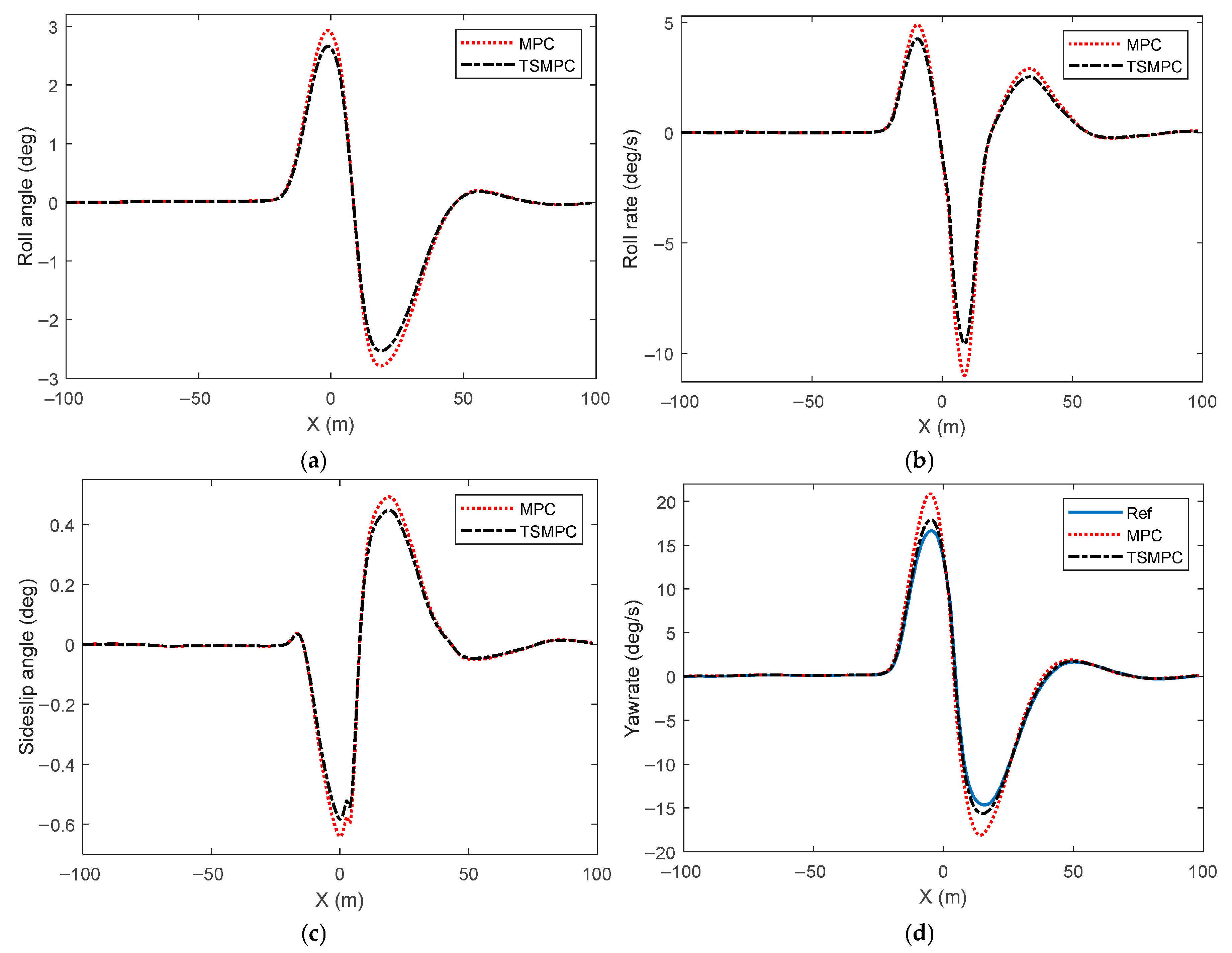
To assess the enhanced stability control capabilities of the TSMPC framework, a comprehensive evaluation was conducted across multiple dynamic performance metrics. Figure 7 shows the comparison of chassis dynamics optimization effects with different model predictive control algorithms. An extensive comparative analysis of roll displacement, roll rate, sprung mass roll angle, and rotational velocity reveals that both control methodologies successfully satisfy vehicular stability requirements in both lateral and vertical dimensions. However, TSMPC has better control performance in various stability control indicators. During high-speed lane transition maneuvers involving abrupt curvature variations in the vehicle’s path, rapid escalation occurs in both roll displacement and angular velocity. Notably, the TSMPC-regulated system demonstrates superior performance by maintaining reduced peak magnitudes of both roll displacement and angular velocity during these critical trajectory segments, which can better ensure the vehicle’s roll stability. Similarly, the TSMPC-regulated system exhibits substantially reduced the vehicle sideslip angle and yaw rate compared to conventional MPC, resulting in enhanced vehicular stability during lateral maneuvers. Figure 8 presents a comparative visualization of key control parameters across different predictive control methodologies, including roll stabilization torque, corrective yaw moment, and front axle steering inputs. The comparative analysis reveals that the TSMPC controller generates more responsive actuation commands, directly contributing to its superior path-following accuracy and dynamic performance.
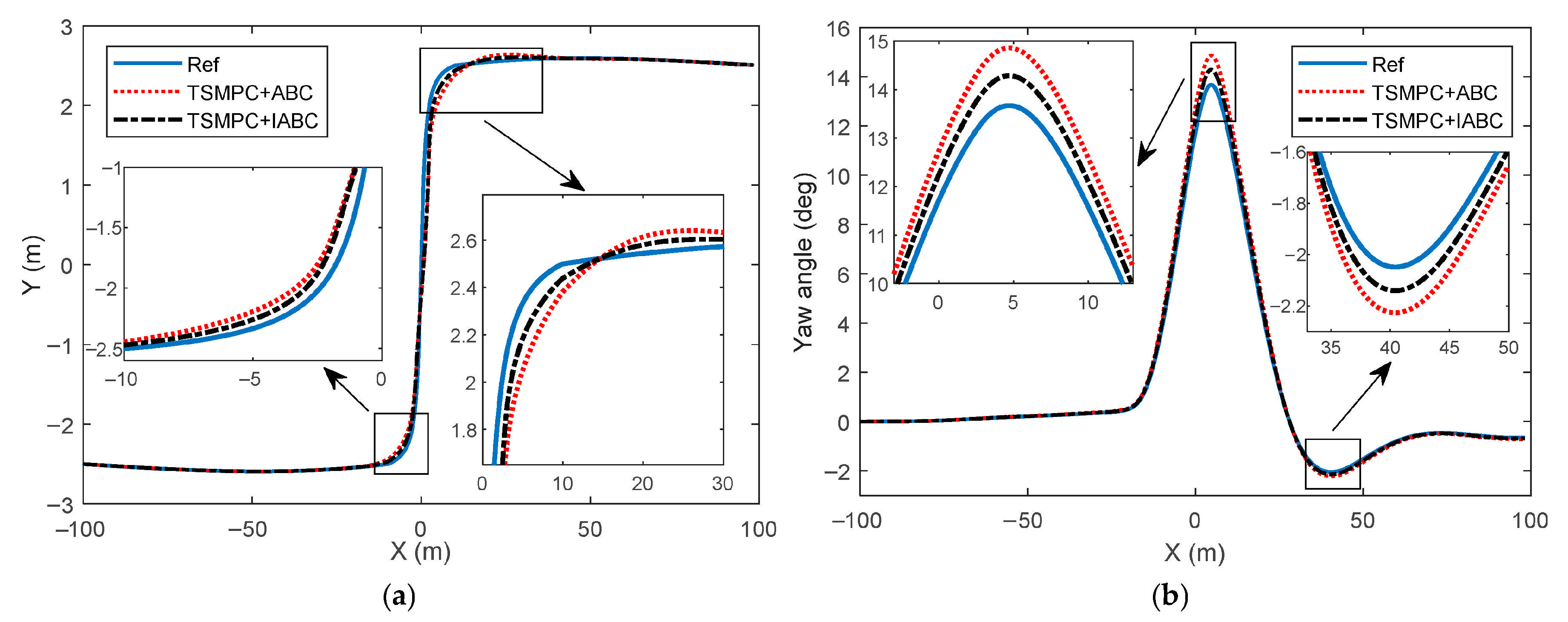
After verifying the application effect of TSMPC algorithm, further test the proposed tire force optimization allocation method based on IABC algorithm and its application effect in vehicle layered coordinated control. In the hierarchical coordinated control of the entire vehicle, the comparative assessment of vehicular performance outcomes across various tire force distribution strategies effectively demonstrates how the novel force optimization approach influences overall system behavior when implementing high-level control objectives. Figure 9 demonstrates the path-following performance achieved through distinct tire force allocation strategies. Figure 10 illustrates the dynamic stabilization performance achieved through various tire force allocation approaches. From Figure 9 and Figure 10, it can be seen that under the same TSMPC algorithm, if ABC and IABC algorithms are used separately in the lower-level controller, the efficacy of path-following and dynamic stabilization varies significantly across different implementation approaches.
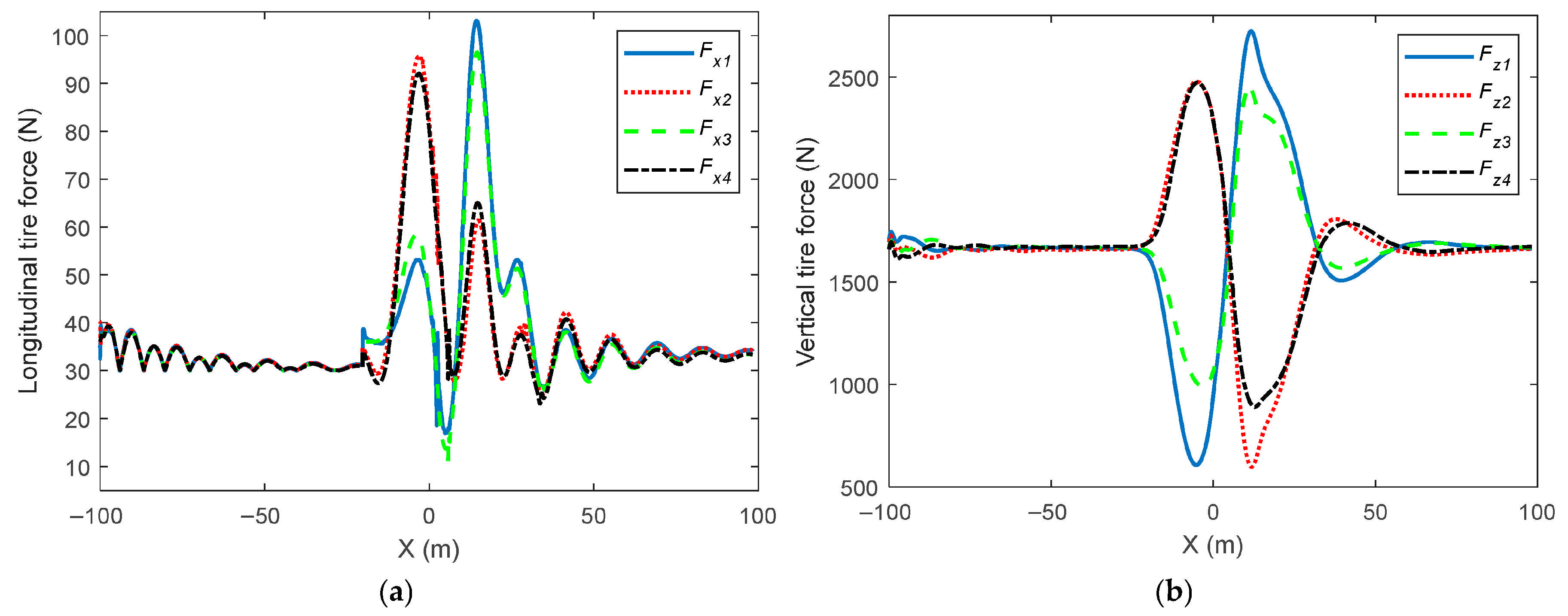
In Figure 9, overall, the trajectory tracking control effect and heading angle tracking effect can maintain high accuracy. However, through the local enlargement, the graphical results demonstrate that the IABC-optimized path exhibits superior responsiveness and handling characteristics during lane transitions, with enhanced tracking precision and computational efficiency compared to conventional ABC implementations. In Figure 10, the TSMPC framework demonstrates robust vehicle stabilization capabilities when integrated with dual tire force optimization methodologies. In contrast, the stability state of the vehicle under ABC algorithm has a certain degree of lag, and its roll angle, roll angle velocity, roll angle, and yaw rate are relatively larger. The comparative analysis substantiates that the developed IABC methodology enhances vehicular path-following precision and dynamic stability through more efficient tire force distribution optimization. The force distribution control results of vehicle tires under IABC algorithm are shown in Figure 11. As shown in the figure, during the initial driving process before changing lanes, the magnitude of longitudinal and vertical tire forces remains basically unchanged and there is no differential distribution between different tires. When the vehicle changes lanes, during cornering maneuvers, the tractive forces acting on the exterior front tire and interior rear tire exhibit substantial escalation, whereas the opposing pair (interior front and exterior rear tires) demonstrate markedly reduced longitudinal force generation compared to their counterparts. At the same time, the variation trend of the amplitude of vertical tire force is basically consistent with the variation trend of longitudinal tire force. This allocation trend helps to reduce steering resistance while meeting the lateral torque requirements and corresponding dynamic control constraints required by the upper-level controller of the vehicle. This enhancement consequently optimizes the comprehensive vehicular dynamic performance and system responsiveness.

5. Conclusions

This study introduces a novel multi-level control framework for autonomous vehicles, integrating TSMPC with IABC optimization. The proposed architecture seeks to enhance vehicular dynamic performance by coordinating high-level motion planning with stability regulation in the supervisory layer, while implementing optimized tire force distribution at the actuator level.
(1)
A comprehensive vehicular dynamics representation was developed, incorporating propulsion, lateral, and rotational motion characteristics while accounting for critical state variables, including the chassis mass slip angle, rotational velocity, and roll displacement. A vehicle path tracking model was constructed, using lateral deviation and heading deviation as evaluation indicators for path tracking performance, and relevant dynamic equations were derived.
(2)
This study presents a two-tiered control framework that stratifies vehicular control into supervisory and actuation layers. The supervisory module orchestrates trajectory following and dynamic stabilization, whereas the actuation module performs optimal tire force distribution. The supervisory control layer implements an incremental predictive TSMPC methodology, capable of addressing time delay systems and multi-constrained optimization challenges while enhancing path-following precision and dynamic stabilization capabilities. The actuation layer adopts an IABC to optimize tire force distribution and meet the lateral and lateral moment requirements specified by the supervisory controller while enhancing vehicular dynamic response characteristics.
(3)
A delay state feedback model predictive controller based on incremental prediction was designed. By defining incremental variables and prediction equations, the system delay problem was solved, and a dual-loop feedforward–feedback architecture was implemented to enhance control precision and computational efficiency. The IABC optimization technique accelerates convergence rates and strengthens global search capabilities through enhanced weight coefficient adaptation during the objective function exploration process.
(4)
Comparative analyses between TSMPC and conventional MPC methodologies demonstrated superior path-following precision, error attenuation, and dynamic stabilization capabilities for the TSMPC approach. Furthermore, the evaluation of the enhanced artificial bee colony technique against its conventional counterpart revealed improved vehicular control performance through optimized tire force distribution.

Author Contributions

Conceptualization, J.L., F.W. and W.G.; methodology, J.L., Z.Z. and T.C.; software, F.W. and S.M.; validation, J.L. and T.C.; writing—original draft preparation, J.L. and W.G.; writing—review and editing, J.L., Z.Z. and T.C.; visualization, F.W. and S.M. All authors have read and agreed to the published version of the manuscript.

Funding

This work was supported by Anyang Institute of Technology’s Doctoral Research Startup Fund Project (no. BSJ2022014); the Key Scientific Research Project Plan of Higher Education Institution of Henan, China (no. 23B460002); National Natural Science Foundation of China (No. 52202472); the Opening Foundation of Key Laboratory of Advanced Manufacture Technology for Automobile Parts, Ministry of Education (no. 2023KLMT06); and the Opening Foundation of Provincial Engineering Research Center for New Energy Vehicle Intelligent Control and Simulation Test Technology of Sichuan (no. XNYQ2024-004).

Data Availability Statement

The original contributions presented in the study are included in the article; further inquiries can be directed to the corresponding author.

Conflicts of Interest

Author Zhengyong Zhou was employed by the Henan Zhenghang Spindle Technology Company Limited. The remaining authors declare that the research was conducted in the absence of any commercial or financial relationships that could be construed as a potential conflict of interest.

References

  1. Boada, B.L.; Viadero-Monasterio, F.; Zhang, H.; Boada, M.J.L. Simultaneous Estimation of Vehicle Sideslip and Roll Angles Using an Integral-Based Event-Triggered H∞ Observer Considering Intravehicle Communications. IEEE Trans. Veh. Technol. 2023, 72, 4411–4425. [Google Scholar] [CrossRef]
  2. Liu, Y.; Gao, H. Stability, scalability, speedability, and string stability of connected vehicle systems. IEEE Trans. Syst. Man Cybern. Syst. 2021, 52, 2819–2832. [Google Scholar] [CrossRef]
  3. Huang, C.; Tang, W.; Wang, J.; Zhang, Z. An Improved Adaptive Car-Following Model Based on the Unscented Kalman Filter for Vehicle Platoons’ Speed Control. Machines 2025, 13, 569. [Google Scholar] [CrossRef]
  4. Jiang, Y.; Meng, H.; Chen, G.P.; Yang, C.N.; Xu, X.J.; Zhang, L.; Xu, H.J. Differential-steering based path tracking control and energy-saving torque distribution strategy of 6WID unmanned ground vehicle. Energy 2022, 254, 124209. [Google Scholar] [CrossRef]
  5. Lee, J.E.; Kim, B.W. A Novel Adaptive Non-Singular Fast Terminal Sliding Mode Control for Direct Yaw Moment Control in 4WID Electric Vehicles. Sensors 2025, 25, 941. [Google Scholar] [CrossRef] [PubMed]
  6. Park, J.Y.; Na, S.; Cha, H.; Yi, K. Direct yaw moment control with 4WD torque-vectoring for vehicle handling stability and agility. Int. J. Automot. Technol. 2022, 23, 555–565. [Google Scholar] [CrossRef]
  7. Wang, X.; Chen, T.; Lu, J. Longitudinal Tire Force Estimation Method for 4WIDEV Based on Data-Driven Modified Recursive Subspace Identification Algorithm. Algorithms 2025, 18, 409. [Google Scholar] [CrossRef]
  8. Chen, X.; Zhang, W.; Bai, H.; Jiang, R.; Ding, H.; Wei, L. A Sigmoid-Based Car-Following Model to Improve Acceleration Stability in Traffic Oscillation and Following Failure in Free Flow. IEEE Trans. Intell. Transp. Syst. 2024, 25, 9039–9057. [Google Scholar] [CrossRef]
  9. Zhao, W.Q. Real-Time Model Predictive Control of Path-Following for Autonomous Vehicles Towards Model Mismatch and Uncertainty. Control Eng. Pract. 2024, 142, 105678. [Google Scholar] [CrossRef]
  10. Cui, K.; He, J.; Yao, X.; Gu, X. Adaptive Model Predictive Control Based on Stability Index for Path Tracking of Autonomous Vehicles Considering Model Error. Proc. Inst. Mech. Eng. Part C J. Mech. Eng. Sci. 2024, 238, 9372–9396. [Google Scholar] [CrossRef]
  11. Qi, G.X. Integrated Control Method for Path Tracking and Lateral Stability of Distributed Drive Electric Vehicles with Extended Kalman Filter-Based Tire Cornering Stiffness Estimation. J. Vib. Control 2024, 30, 567–582. [Google Scholar] [CrossRef]
  12. Li, H.; Li, B.; Yang, H.; Mu, C. Nonlinear Model Predictive Control for Time-Optimal Turning Around of an Autonomous Vehicle Under Steering Lag. IEEE/ASME Trans. Mechatron. 2025, 30, 577–586. [Google Scholar] [CrossRef]
  13. Meng, D.; Chu, H.; Tian, M.; Gao, B.; Chen, H. Real-Time High-Precision Nonlinear Tracking Control of Autonomous Vehicles Using Fast Iterative Model Predictive Control. IEEE Trans. Intell. Veh. 2024, 9, 3644–3657. [Google Scholar] [CrossRef]
  14. Liang, J.; Tian, Q.; Feng, J.; Pi, D.; Yin, G. A Polytopic Model-Based Robust Predictive Control Scheme for Path Tracking of Autonomous Vehicles. IEEE Trans. Intell. Veh. 2024, 9, 3928–3939. [Google Scholar] [CrossRef]
  15. Wan, Z.; Xu, C.; Li, B.; Li, Y.; Ye, F. Trajectory Tracking Method of Four-Wheeled Independent Drive and Steering AGV Based on LSTM-MPC and Fuzzy PID Cooperative Control. Electronics 2025, 14, 2000. [Google Scholar] [CrossRef]
  16. Huang, K.; Wei, K.; Li, F.; Yang, C.; Gui, W. LSTM-MPC: A Deep Learning Based Predictive Control Method for Multimode Process Control. IEEE Trans. Ind. Electron. 2022, 70, 11544–11554. [Google Scholar] [CrossRef]
  17. Guo, N.; Zhang, X.; Zou, Y.; Lenzo, B.; Du, G.; Zhang, T. A Supervisory Control Strategy of Distributed Drive Electric Vehicles for Coordinating Handling, Lateral Stability, and Energy Efficiency. IEEE Trans. Transp. Electrif. 2021, 7, 2488–2504. [Google Scholar] [CrossRef]
  18. Hua, X.; Xiang, K.; Cheng, X.; Ning, X. An Adaptive Compound Control Strategy of Electric Vehicles for Coordinating Lateral Stability and Energy Efficiency. Appl. Sci. 2025, 15, 3347. [Google Scholar] [CrossRef]
  19. Liu, W.; Zhang, J.; Ma, R.; He, C. Cascade-Free Predictive Wheel Slip Control with Discrete-Valued Inputs for Automotive Hydraulic Anti-lock Braking Systems. IEEE Trans. Transp. Electrif. 2024, 11, 6048–6059. [Google Scholar] [CrossRef]
  20. Lee, J.E.; Kim, B.W. Improving Direct Yaw-Moment Control via Neural-Network-Based Non-Singular Fast Terminal Sliding Mode Control for Electric Vehicles. Sensors 2024, 24, 4079. [Google Scholar] [CrossRef]
  21. Liu, H.; Yan, S.; Shen, Y.; Li, C.; Zhang, Y.; Hussain, F. Model predictive control system based on direct yaw moment control for 4WID self-steering agriculture vehicle. Int. J. Agric. Biol. Eng. 2021, 14, 175–181. [Google Scholar] [CrossRef]
  22. Tao, Y.; Ge, C.; Feng, H.; Xue, H.; Yao, M.; Tang, H.; Liao, Z.; Chen, P. A novel approach for adaptively separating and extracting compound fault features of the in-wheel motor bearing. ISA Trans. 2025, 159, 337–351. [Google Scholar] [CrossRef] [PubMed]
  23. Micheli, F.; Bersani, M.; Arrigoni, S.; Braghin, F.; Cheli, F. NMPC Trajectory Planner for Urban Autonomous Driving. Veh. Syst. Dyn. 2023, 61, 1387–1409. [Google Scholar] [CrossRef]
  24. Zou, T.; You, Y.; Meng, H.; Chang, Y. Research on Six-Wheel Distributed Unmanned Vehicle Path Tracking Strategy Based on Hierarchical Control. Biomimetics 2022, 7, 238. [Google Scholar] [CrossRef] [PubMed]
  25. Wang, Z.J.; Zhou, X.Y.; Wang, J.M. Extremum-Seeking-Based Adaptive Model-Free Control and Its Application to Automated Vehicle Path Tracking. IEEE-ASME Trans. Mechatron. 2022, 27, 3874–3884. [Google Scholar] [CrossRef]
  26. Picotti, E.; Mion, E.; Libera, A.D.; Pavlovic, J.; Censi, A.; Frazzoli, E.; Beghi, A.; Bruschetta, M. A Learning-Based Nonlinear Model Predictive Controller for a Real Go-Kart Based on Black-Box Dynamics Modeling Through Gaussian Processes. IEEE Trans. Control Syst. Technol. 2023, 31, 2034–2047. [Google Scholar] [CrossRef]
  27. Pinho, J.; Costa, G.; Lima, P.U.; Ayala Botto, M. Learning-Based Model Predictive Control for Autonomous Racing. World Electr. Veh. J. 2023, 14, 163. [Google Scholar] [CrossRef]
  28. Manzano, J.M.; Limon, D.; noz de la Peña, D.M.; Calliess, J.P. Robust learning-based MPC for nonlinear constrained systems. Automatica 2020, 117, 108948. [Google Scholar] [CrossRef]
  29. Feng, H.; Tao, Y.; Feng, J.; Zhang, Y.; Xue, H.; Wang, T.; Xu, X.; Chen, P. Fault-tolerant collaborative control of four-wheel-drive electric vehicle for one or more in-wheel motors’ faults. Sensors 2025, 25, 1540. [Google Scholar] [CrossRef]
  30. Sun, Y.; Ning, H.; Wang, H.; Wang, C.; Zheng, J. Trajectory Tracking Control Design for 4WS Vehicle Based on Particle Swarm Optimization and Phase Plane Analysis. Appl. Sci. 2024, 14, 3664. [Google Scholar] [CrossRef]
  31. Li, L.; Pei, W.; Zhang, Q. Research on Intelligent Vehicle Tracking Control and Energy Consumption Optimization Based on Dilated Convolutional Model Predictive Control. Energies 2025, 18, 2588. [Google Scholar] [CrossRef]
  32. Zhang, Z.; Ding, H.; Guo, K.; Zhang, N. A Hierarchical Control Strategy for FWID-EVs Based on Multi-Agent with Consideration of Safety and Economy. Energies 2022, 15, 9112. [Google Scholar] [CrossRef]
  33. Hewing, L.; Wabersich, K.P.; Menner, M.; Zeilinger, M.N. Learning-Based Model Predictive Control: Toward Safe Learning in Control. Annu. Rev. Control Robot. Auton. Syst. 2020, 3, 269–296. [Google Scholar] [CrossRef]
  34. Li, X.; Lan, Y.; Jiang, P.; Cao, H.; Zhou, J. An efficient computation for energy optimization of robot trajectory. IEEE Trans. Ind. Electron. 2021, 69, 11436–11446. [Google Scholar] [CrossRef]
  35. Rokonuzzaman, M.; Mohajer, N.; Nahavandi, S. Effective adoption of vehicle models for autonomous vehicle path tracking: A switched MPC approach. Veh. Syst. Dyn. 2023, 61, 1236–1259. [Google Scholar] [CrossRef]
  36. Hu, Y.; Fu, J.; Wen, G. Safe reinforcement learning for model-reference trajectory tracking of uncertain autonomous vehicles with model-based acceleration. IEEE Trans. Intell. Veh. 2023, 8, 2332–2344. [Google Scholar] [CrossRef]
  37. Napolitano Dell’Annunziata, G.; Ruffini, M.; Stefanelli, R.; Adiletta, G.; Fichera, G.; Timpone, F. Four-Wheeled Vehicle Sideslip Angle Estimation: A Machine Learning-Based Technique for Real-Time Virtual Sensor Development. Appl. Sci. 2024, 14, 1036. [Google Scholar] [CrossRef]
  38. Hu, J.; Liu, Y.; Xiao, F.; Lin, Z.; Deng, C. Coordinated Control of Active Suspension and DYC for Four-Wheel Independent Drive Electric Vehicles Based on Stability. Appl. Sci. 2022, 12, 11768. [Google Scholar] [CrossRef]
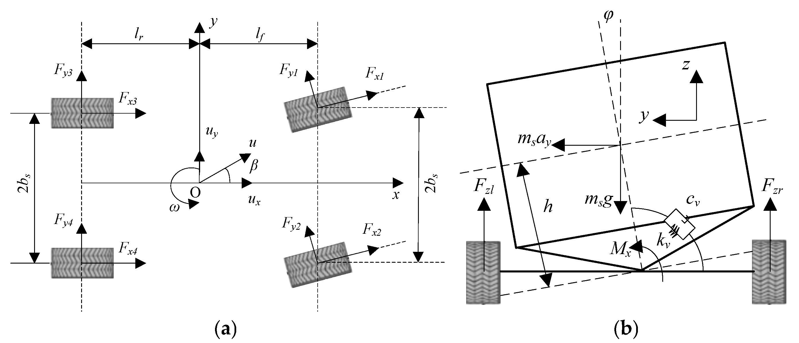
Figure 1. Vehicle dynamic models: (a) lateral dynamic model; (b) vertical dynamic model.
Algorithms 18 00508 g001
Figure 2. Vehicle trajectory tracking model.
Algorithms 18 00508 g002
Figure 3. Architecture of hierarchical coordination control strategy.
Algorithms 18 00508 g003
Figure 4. Calculation flowchart of IABC algorithm.
Algorithms 18 00508 g004
Figure 5. Comparison of trajectory tracking performance under different model predictive control algorithms. (a) Vehicle trajectory; (b) heading angle.
Algorithms 18 00508 g005
Figure 6. Comparison of trajectory tracking errors under different model predictive control algorithms. (a) Lateral deviation; (b) heading deviation.
Algorithms 18 00508 g006
Figure 7. Comparison of vehicle stability control effects under different model predictive control algorithms. (a) Roll angle; (b) roll angle velocity; (c) center of mass roll angle; (d) yaw rate.
Algorithms 18 00508 g007
Figure 8. Vehicle control variables under different model predictive control algorithms. (a) Roll moment; (b) yaw moment; (c) front-wheel steering angle.
Algorithms 18 00508 g008
Figure 9. Comparison of vehicle trajectory tracking performance under different tire force distribution methods. (a) Vehicle trajectory; (b) heading angle.
Algorithms 18 00508 g009
Figure 10. Comparison of vehicle stability control effects under different tire force distribution methods. (a) Roll angle; (b) roll angle velocity; (c) center of mass roll angle; (d) yaw rate.
Algorithms 18 00508 g010
Figure 11. Improved vehicle tire force allocation control results under artificial bee colony algorithm. (a) Longitudinal tire force; (b) vertical tire force.
Algorithms 18 00508 g011
Disclaimer/Publisher’s Note: The statements, opinions and data contained in all publications are solely those of the individual author(s) and contributor(s) and not of MDPI and/or the editor(s). MDPI and/or the editor(s) disclaim responsibility for any injury to people or property resulting from any ideas, methods, instructions or products referred to in the content.