Abstract
The gas-gathering pipeline network is a critical infrastructure for collecting and conveying natural gas from the extraction site to the processing facility. This paper introduces a design optimization model for a star–tree gas-gathering pipeline network within a discrete space, aimed at determining the optimal configuration of this infrastructure. The objective is to reduce the investment required to build the network. Key decision variables include the locations of stations, the plant location, the connections between wells and stations, and the interconnections between stations. Several equality and inequality constraints are formulated, primarily addressing the affiliation between wells and stations, the transmission radius, and the capacity of the stations. The design of a star–tree pipeline network represents a complex, non-deterministic polynomial (NP) hard combinatorial optimization problem. To tackle this challenge, a hierarchical optimization framework coupled with an improved genetic algorithm (IGA) is proposed. The efficacy of the genetic algorithm is validated through testing and comparison with other traditional algorithms. Subsequently, the optimization model and solution methodology are applied to the layout design of a pipeline network. The findings reveal that the optimized network configuration reduces investment costs by 16% compared to the original design. Furthermore, when comparing the optimal layout under a star–star topology, it is observed that the investment needed for the star–star topology is 4% higher than that needed for the star–tree topology.
1. Introduction
1.1. Motivation
Currently, the global community is transitioning into an era characterized by clean and efficient energy, with natural gas emerging as the predominant energy source. According to the Global Energy Outlook, worldwide consumption of natural gas is projected to increase continuously until 2050, with an average annual growth rate exceeding 1.4% (Richard, 2020). The significant rise in natural gas demand necessitates enhanced efforts toward the construction of surface gas-gathering pipeline networks. The investment required for gas-gathering pipeline networks is substantial, often comprising over 30% of the total development costs of a gas field [1]. Consequently, optimizing the design of these pipeline networks in a rational manner can yield considerable economic benefits.
The system typically includes wells, gas-gathering stations, central treatment facilities, and pipelines (Figure 1). Initially, the natural gas extracted from the wells is conveyed to the gas-gathering station via production pipelines. Once collected at the gas-gathering station, the gas is then transported through gathering pipelines to the central treatment plant for purification, ensuring it meets the standards required for external distribution. Based on network topology, gas-gathering pipeline networks can be categorized into three fundamental types: star, tree, and cyclic topologies [2]. In a star topology, multiple wells are directly connected to a single station, as illustrated in Figure 2a. In a tree topology, wells are linked to the station through adjacent wells, as depicted in Figure 2b. A cyclic topology involves interconnected wells forming a loop, as shown in Figure 2c.
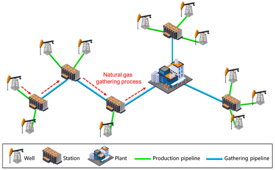
Figure 1.
Typical gas-gathering pipeline network.

Figure 2.
Pipeline network structure: (a) star topology, (b) tree topology, (c) cyclic topology.
In practical large-scale gas-gathering pipeline networks, various topological combinations are often observed. At present, in the actual construction of gas fields, based on a variety of factors, including gas well distribution, construction cost, management convenience, operation efficiency, etc., star–star topology network structures and star–tree topology network structures have been widely used in gas field development. The star–star topology network structure of multiple gas wells directly connected to a central gas-gathering site makes the layout simple and easy to manage and control. Its advantages are that the total length of the pipeline can be reduced, the initial construction cost can be reduced, and it is convenient to centrally process and transport the natural gas produced by the gas field, which is suitable for a gas field with a small gas-bearing area, a large number of wellheads, and a low output of a single well. The star–tree topology network structure combines the characteristics of the star and dendritic structures. In this structure, each gas well and its gas-collecting stations are connected by a star shape, and the gas-collecting stations are connected by gas-collecting trunk lines to form a dendritic structure. This layout balances the cost and efficiency of the long-haul collection line, while providing some flexibility to adjust and expand according to the stage of development of the field. Figure 3 illustrates a typical star–tree gas-gathering pipeline network. This network structure is particularly suitable for scenarios where wells within local blocks are concentrated, but these blocks are widely dispersed with significant distances between them.
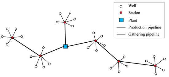
Figure 3.
Star–tree pipeline network.
In general, the optimization problem can be categorized into design optimization and operational optimization [3]. Design optimization involves selecting the most suitable layout configuration, station placements, pipe sizes, and equipment scales for a new pipeline network to achieve optimal construction investment costs. Operational optimization, on the other hand, focuses on refining the operational strategies of the established pipeline network, which includes optimizing pipeline flows and node pressure parameters to meet technical or economic objectives.
The layout optimization challenge of gas-gathering pipeline networks encompasses several subprocesses, such as well grouping, station and plant location determination, and establishing connectivity among facilities [4]. Figure 4 depicts the layout optimization process. In addition, the determination of station (or plant) location is divided into two scenarios. The first scenario is that the station can be built at any location within the gas field. The second scenario is that the station must be jointly built with the well to save on construction investment costs. In other words, the station location can only be selected from the existing well location, which is defined as the station location selection in a discrete space. Since this scenario is more widely used in engineering practice, this paper will focus on this problem.
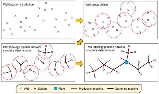
Figure 4.
Hierarchical optimization diagram.
1.2. Literature Review
Based on literature research, it is evident that the academic community has conducted extensive studies on optimizing the design of gas pipeline networks. These studies primarily focus on modeling and solving optimization challenges related to network layout. Depending on the topology of the pipeline network—such as star, tree, and cyclic topologies—different optimization problems arise. Sanaye and Mahmoudimehr [5] developed an optimization model for tree topology gas pipeline networks, which considers parameters like network layout, pipe diameter, and node pressures. Rodriguez et al. [6] investigated the design of multi-level star networks, addressing optimal configurations and facility placements. Fu [7] explored the multi-objective optimization design of ring-type oil-gathering pipeline networks. Wang et al. [8] formulated a multi-period MILP (Mixed Integer Linear Programming) model for optimizing tree topology networks, accounting for terrain and obstacles. Zhou et al. [9] established an MINLP (Mixed Integer Nonlinear Programming) model for optimizing two-level star topology pipeline networks for underground natural gas storage.
Regarding the optimization solving methods, early research predominantly utilized operation research techniques, particularly heuristic algorithms, to address the gas-gathering pipeline network optimization models. From a mathematical optimization and operation research perspective, designing optimal gas-gathering pipeline networks is classified as an NP-hard combinatorial optimization problem, which poses significant challenges and finds application across various industrial domains [10,11]. Balinski [12] formulated an optimization model for site placement in discrete spaces with unlimited site capacities, which was primarily solved using heuristic algorithms. Common exact algorithms include the branch and bound method, cutting plane algorithm, and column generation algorithm [13,14]. However, traditional optimization theories often struggle to efficiently solve problems with natural gas pipeline network models due to lengthy computational times and occasional mismatches between theoretical outcomes and practical applications.
In recent years, commercial solvers and heuristic algorithms have gradually become the most common way to deal with pipeline network layout optimization. A commercial solver can eliminate the tedious algorithm programming work, but the solution method is limited, and it is difficult to modify the built-in parameters of the algorithm. The heuristic algorithm has a large programming workload, but the algorithm has good scalability and can even combine the advantages of several algorithms to obtain the optimization results. Uester and Dilaveroglu [15] solved a gas pipeline network design and expansion optimization problem using the online Bonmin solver. Zhang et al. [16] developed a comprehensive MILP layout optimization model that incorporates terrain and obstacle considerations. There are also scholars who use graph theory methods and machine learning methods to solve optimization problems [17,18]. They utilized the Gurobi solver to globally solve the model. Rosa et al. [19] introduced a practical and efficient optimization approach for subsea production networks using the GAMS solver. Liu et al. [20] put forward an enhanced particle swarm optimization algorithm with enhanced global search capabilities to tackle the MINLP model for optimizing pipeline network layouts. Hong et al. [21] proposed a pipeline network layout optimization model that accounts for hydraulic characteristics and employed an ant colony algorithm for its solution.
1.3. Contributions
Gas field surface investment accounts for about 30% to 40% of the total development investment cost, and the proportion of investment in the construction of surface-level gathering and transportation pipeline networks often accounts for 60% to 70% of the surface investment cost. It can be seen that a natural gas-gathering and transmission pipeline network occupies an important position in the construction of gas field ground engineering, and its design optimization can significantly improve the economic benefits. At present, some traditional optimization methods are not sufficient for the study of multi-level structures of pipeline networks and the discovery of an effective solution. Therefore, this paper proposes a set of optimization methods for the more complex star–tree gas-gathering pipeline network in discrete spaces.
Based on the literature reviewed, scholars have made significant strides in the design optimization of gas pipeline networks. However, their focus has primarily been on optimizing single-network topologies, neglecting the complexity introduced by multiple topological combinations, particularly the star–tree multi-level configurations prevalent in oil and gas fields. The inclusion of diverse network types significantly escalates the complexity of solving these models. We approach this issue as follows:
- (1)
- We stablish an MINLP model for the optimal design of star–tree networks in discrete space.
- (2)
- A hierarchical optimization framework is proposed. The first stage focuses on optimizing the design of the star topology pipeline network connecting wells to stations. The second stage involves optimizing the design of the tree topology pipeline network connecting stations to plants.
- (3)
- An improved genetic algorithm (IGA) is proposed, and the Kruskal algorithm is used to achieve optimal layout solutions for the tree network.
2. Mathematical Model
Inside the natural gas-gathering and transportation pipeline network layout, there are two main types of models: one is an MIP model and the other is an MINLP model. In the MIP model, various point-to-point distances are calculated in advance. For the development of gas fields, the scale of the number of wells is very large, and the calculation of the distance in advance is very large; therefore, in the model of this paper, the pipeline length from wells to stations and the pipeline length between stations are both Euclidean distances, which are nonlinear equations, respectively, and , which can improve the solving efficiency. In addition, the station location decision variable (), plant location decision variable (), and pipeline connection decision variable (,) are binary variables. Therefore, the model in this paper is an MINLP one. The model has good scalability, which would allow for the number of nodes to be increased in the future.
2.1. Objective Function
An MINLP model is proposed. The minimum investment is used as the objective function of the model, as shown in Equation (1).
where is the pipeline network investment, CNY. is the production pipeline investment, CNY. is the gathering pipeline investment, CNY. is the station investment, CNY. is the plant investment, CNY.
(1) Production pipeline investment.
The investment in production pipelines is the cost of connecting all wells and stations in the network, as shown in Equation (2).
where is the connection decision variable between wells and stations, 0 or 1. is the price of the pipeline between wells and stations, CNY/m. is the pipeline length from wells to stations, m. , is the well coordinate, and is the station coordinate.
(2) Gathering pipeline investment.
The investment in gathering pipelines is the cost of connecting the pipelines between all stations in the network, as shown in Equation (3).
where is the connection decision variable between stations, 0 or 1. is the price of the pipeline between stations, CNY/m. is the pipeline length between stations, m. , , and are the stations or plant coordinate.
(3) Station investment.
The station investment is the sum of the investment costs of all stations in the network, as shown in Equation (4).
where is the station location decision variable, 0 or 1. is the cost of the station, CNY.
(4) Plant investment.
The plant investment is the sum of the investment costs of all plants in the pipeline network, as shown in Equation (5).
where is the plant location decision variable, 0 or 1. is the cost of plant, CNY.
2.2. Constraints
(1) Uniqueness constraint of well connections.
Each well is exclusively associated with one station, as shown in Equation (6).
(2) Plant number constraint.
There exists a single plant within the pipeline network, as shown in Equation (7).
(3) Well and station affiliation constraint.
Well i can be assigned to station j when station j exists, as shown in Equation (8).
(4) Transmission radius constraint.
The gas pressure may decrease during transportation due to pipe friction. In order to keep the pressure drop within a reasonable range, the distance between the well and the station should be less than a specific value, known as the transmission radius, as shown in Figure 5.
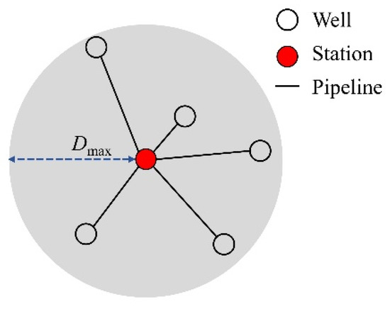
Figure 5.
Schematic diagram of the transmission radius.
As such, the transmission radius constraint is calculated as shown in Equation (9).
where is the maximal allowable pipeline length from the well to the station, m.
(5) Station capacity constraint.
Generally, the gathering radius constraint is not considered when addressing the station capacity constraint, which falls under the capacitated facility location problem (CFLP). In this paper, both the radius constraint and the capacity constraint are considered. When the gathering radius constraint is satisfied but the capacity constraint is not, the pipeline network layout will be redesigned, as shown in Figure 6.
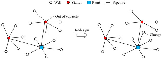
Figure 6.
Pipeline network redesigns in violation of capacity constraints.
Thus, the capacity of a station must not exceed that shown in Equation (10).
where is the node gas flow of station j, m3/d. is the capacity of the station, m3/d.
(6) Tree structure constraint.
The tree connection constraint ensures that the generated topology is the shortest and loop-free, as shown in Equation (11).
(7) Node flow constraint.
The node flow constraint ensures that the total gas volume remains constant, as shown in Equation (12).
where is the node gas flow of well i, m3/d. is the node flow of plant k, m3/d.
2.3. Decision Variables
The decision variables include the station location decision variable (), plant location decision variable (), and pipeline connection decision variable (,). All these decision variables are binary variables, as shown in Equation (13).
3. Solving Method
The design optimization of a star–tree pipeline network is recognized as NP-hard, presenting challenges for finding a comprehensive solution [22]. To address this, a hierarchical optimization framework is proposed in this study. The framework consists of two stages: the first stage involves determining well group division and station locations within the star topology network, while the second stage focuses on establishing station connections and plant locations in the tree topology network. Notably, optimizing the star topology network in the first stage serves as the foundational and pivotal component of the entire optimization problem. Its complexity and scale exceed those of the second-stage tree topology network optimization. Therefore, this paper concentrates on enhancing the design optimization and introduces an IGA tailored to address this challenge. Additionally, the Kruskal algorithm, leveraging the minimum spanning tree approach, is employed for the second-stage tree topology pipeline network design optimization.
3.1. Basic Genetic Algorithm
A GA is a heuristic search method that draws inspiration from the principles of natural selection and genetics. It aims to optimize the allocation of facilities by simulating the evolutionary process of biological chromosomes. The basic solving process of GA [23], unfolds as follows:
- (1)
- Encoding: encode the information on the distribution of wells and stations into the chromosome sequence.
- (2)
- Generating initial population: a fixed size of chromosomes (individuals) is randomly generated to form the initial population P(t) (in this paper, 200 groups are generated). Here, t denotes the evolutionary generation counter, and T represents the maximum number of evolution cycles set for the algorithm.
- (3)
- Fitness function: each individual in the population is evaluated based on a fitness function, typically using the total investment value as the criterion for evaluation.
- (4)
- Selection and inheritance: the initial population is selected and crossed by simulating the process of biological evolution, and the next generation population P(t + 1) is obtained through step 3.
- (5)
- Termination condition judgment: when t ≤ T, then t + 1 replaces t, and we go to step 2; if t > T, we regard the individual with optimal fitness through the process of evolution as the optimal solution and terminate the operation [24].
The above process is also described by the flow diagram shown in Figure 7.
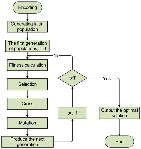
Figure 7.
Flow diagram of the basic GA.
3.2. Algorithm Improvement
Considering the discrete nature of the space and the specific structure of gas field pipeline networks, the traditional GA and its associated parameters may not fully align with the mathematical model proposed in this paper. Therefore, it is essential to enhance the basic GA to better suit these characteristics and optimize the pipeline network design effectively. The improvement includes the overall coding of well–station correspondence, the formulation of the fitness function of the network solution, and the redesign of the crossover operator and mutation operator.
(1) Coding design.
Taking into account the characteristics of the constraints, using the connection relationship between wells and stations as a coding basis, real number coding is used to improve the efficiency of the GA. The chromosome-encoding sequence is structured such that it directly impacts the objective function, which in this case is the total investment. Each chromosome’s length corresponds to the total number of wells, and within the sequence, the identifier of each well is systematically represented in ascending order. This encoding method ensures that the GA optimally addresses the design constraints and effectively targets the optimization of the gas pipeline network’s configuration. Each well’s corresponding station number is stochastically generated at every position within the chromosome to denote the linkage between the well and its respective station. In the proposed chromosome coding scheme, each digit in a chromosome = (C1, C2, … Cm) represents the number of the station corresponding to each well.
(2) Crossover operator design.
For the GA, the crossover operation method and cross probability are extremely important parameters which directly affect the optimization quality of the algorithm. Using CAP101 data based on OR-LIBRARY (50 wells, 25 stations) [25], the crossover operation method and crossover probability are tested for their influence on the solution, and the best crossover mode and crossover probability are determined.
Each of the crossover techniques was tested 50 times, and their results were averaged for comparison. As the iterative generations increased, the algorithm progressively converged toward the optimal solution. Among the various crossover methods evaluated, the multi-point crossover method demonstrated a superior performance, leading to its selection. Figure 8 illustrates the average test outcomes.
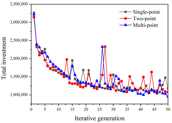
Figure 8.
Convergence curve of different crossover operation methods.
The crossover probability varies between 0.5 and 0.9. A comparison of the effects of these different crossover probabilities on the results was conducted by averaging the outcomes from 50 tests. When the crossover probability is between 0.7 and 0.9, the results are similar. Increasing the crossover probability properly can improve the convergence of the solution, so the crossover probability should be kept at a high value in the design. Figure 9 shows the effect of different crossover probabilities on the results in the multi-point crossing method.
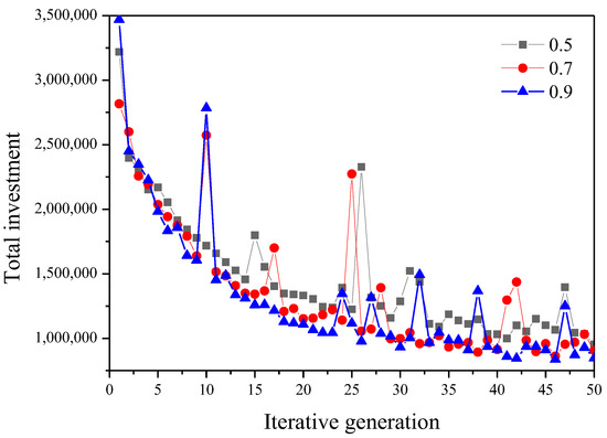
Figure 9.
Convergence curve of different crossover probabilities.
(3) Mutation operator design.
The mutation operator is a measure that prevents the GA from falling into the local optimum by simulating the genetic and evolutionary values of the rupture allele [26]. In the process of debugging the mutation operator, a variation function is tested for the GA to mitigate the risk of falling into local optima in later stages. The mutation operators employ an adaptive approach, as indicated in Formula (14).
where is the mutation probability; is the fitness value; and are the maximum and minimum fitness value of each generation; and is the mutation coefficient.
Through testing, it was found that when the mutation coefficient is below 0.003, the iterative stability and convergence of the whole solution process is better, and the solution time is more reasonable; however, if the mutation coefficient has a value of more than 0.1, the determined solution may be far away from the optimal solution, affecting the stability of the iteration and the speed of convergence and other problems. Therefore, the mutation coefficient was chosen to be below 0.003.
The impact of mutation probability on investments is depicted in Table 1. These experiments on CAP101 demonstrate that when the mutation probability is set to a specific value, it ensures population diversity without compromising the convergence of the GA toward the global optimal solution. The main reason for this is that when real number coding is used, each position on each chromosome contains more information than when other encoding methods are used, and when the mutation probability is high, it is easy to directly destroy the dominant individual.

Table 1.
Impact of varying mutation probabilities on GA performance.
3.3. IGA Testing
To better address the optimal design of star–tree pipeline networks in discrete spaces, this paper emphasizes enhancements to the coding scheme, crossover operator, and mutation operator of the foundational GA. The solving steps of the IGA are shown in Figure 10.
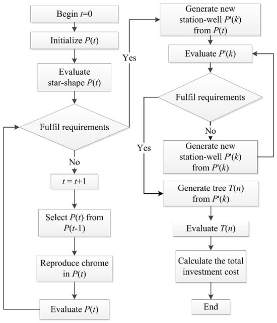
Figure 10.
Flow diagram of the IGA.
To validate the effectiveness of the modified genetic algorithm in solving the pipeline network layout design problem, a series of algorithm tests were conducted. All algorithms were implemented in MATLAB 2022 software. The numerical experiments were executed on a computer equipped with an Intel(R) Core (TM) i5-2450M CPU @ 2.50 GHz, 4 GB of RAM, and the Windows 7 operating system.
Two classical algorithms were selected for comparison with the improved GA, namely constriction factor particle swarm optimization (CPSO) and tabu search (TABU). Several problems in the OR-LIBRARY were utilized for algorithmic testing, and the solution outcomes are presented in Table 2. LOCAL is the actual optimal solution. n stands for well number. m stands for station number. For smaller numbers of wells and stations, such as in the case of CAP101, the benefits of using the IGA are not readily apparent. In fact, the IGA may require more computation time compared to other algorithms. However, as the numbers of n (wells) and m (stations) increase, the advantages of the IGA’s efficiency in solving problems become increasingly evident. It tends to converge to the optimal solution more swiftly than other algorithms as n and m grow larger.

Table 2.
Comparison with other algorithms.
3.4. Kruskal Algorithm
When connecting each station using a tree topology, the fundamental task is to address the minimum spanning tree problem. In the design of the minimum spanning tree, commonly used algorithms include the Prim algorithm and Kruskal algorithm, whose kernel is based on the greedy principle. By comparing the two algorithms, it was found that the Kruskal algorithm is always superior to the Prim algorithm in solving time, so we chose to use the Kruskal algorithm as the tree topology network design algorithm. The Kruskal algorithm is a spanning tree algorithm based on weighted edges. In the process of solving, the smallest weighted edge is successively selected and added to the tree set. When the added edge generates a cyclic topology, the weighted edge is removed, until all edges have been selected [27].
The solving process of the Kruskal algorithm is shown in Figure 11. All nodes are divided into the join node set and the unjoined scatter node set . At the beginning, and . Firstly, the nodes that form the shortest edge are selected and added to the join node set, that is and . Then, in the same way, edges , , , and are selected to the join node set. When a cyclic typology is created, the edge that produced it is removed and the solution is complete. Finally, and .
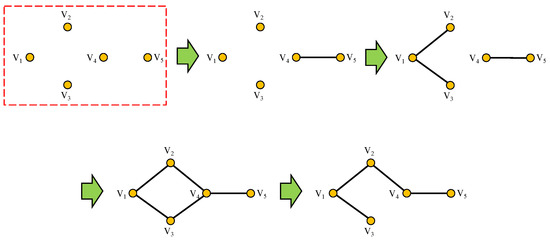
Figure 11.
Schematic diagram of Kruskal algorithm solving process.
4. Results and Discussion
For a natural gas field gathering and transmission pipeline network system, the layout design is an NP problem, which is not conducive to calculation. In order to improve the efficiency of the solution, the following four assumptions are made: (1) For the external conditions of the calculation in the layout design, the standard conditions become the default for calculation (pressure of 0.1 MPa, temperature of 20 °C). (2) The flow rate in the gas pipeline is unstable. In order to solve the problem of convenience, the gas flow in the pipeline is simplified as a stable flow. (3) In the pipeline flow, the temperature of the buried pipeline usually changes with the length of the pipeline, and when the pipeline is too long, the gas will eventually become close to the ambient temperature. In order to facilitate the calculations, and since the gathering pipeline network is usually located in the same area, the temperature of the pipeline is assumed to be constant in this paper. (4) For the direction of the flow of the gas in the network, it is stipulated that each node can only transport the gas from one direction to another.
An actual natural gas pipeline network in China was selected for analysis and search for a solution [28]. The original layout of the pipeline network in the gas field is depicted in Figure 12. This gas field comprises 93 wells, with each producing between 2000 and 5000 m3/d of gas, with wellhead pressures ranging from 0.2 to 1.0 MPa and an average production temperature of 20 °C. The specification of the primary production pipelines between wells and stations was De160 × 9.5 mm, while the specification of the secondary gathering pipelines between stations (and the plant) was De225 × 12.8 mm. Detailed costs are provided in Table 3.
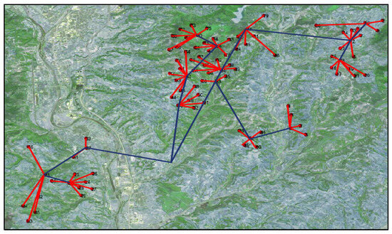
Figure 12.
Sketch of the original pipeline network layout.

Table 3.
Projected costs of the pipeline network.
The maximum radius constraint was 1.5 km, and the processing capacity of a single station was 20,000 m3/day. Since the data came from a low-pressure gas field, pressure constraints were not considered in this case. In the original algorithm (GA), the calculation took more than 2 h at a time. After optimizing the algorithm structure (IGA), the calculation time was shortened to 15–30 min, increasing the calculation efficiency by over 400%. The IGA was used to solve the layout of pipeline network.
Utilizing the established hierarchical optimization framework, we derived an optimized layout scheme. The initial star topology layout in the first stage is illustrated in Figure 13. Figure 14 displays the results of well grouping and station location determination. The final optimized layout is depicted in Figure 15. This network consists of fourteen gas-collecting stations and one treatment plant, which is one station fewer than the original gas field design.
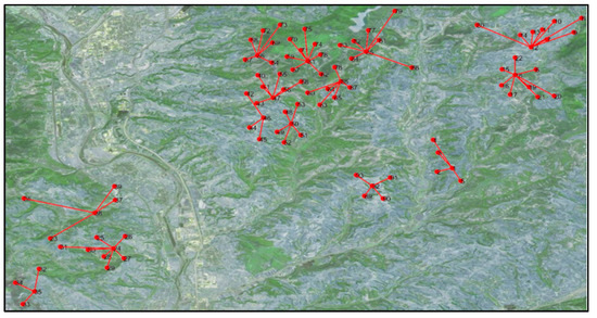
Figure 13.
Connection relationship between wells and stations.
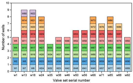
Figure 14.
Results for well allocation, station location, and plant location.
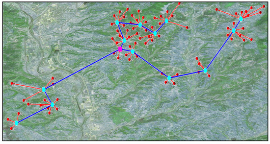
Figure 15.
Design result for star–tree pipeline network layout.
Using the simulation software to verify the feasibility of the pipeline network layout structure, and considering that the number of wells in the pipeline network was too large, the number of wells was determined as the sum of the gas volume and the node of the valve manifold for the connection verification. The connection diagram is shown in Figure 16. Corresponding pressure drop calibration is shown in Figure 17. The pressure drop was within the allowable pressure drop range, meeting the requirements of gas transmission.
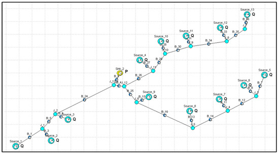
Figure 16.
Illustration of pipeline network connection simulation.
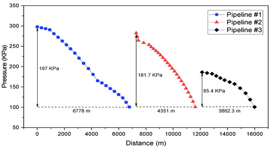
Figure 17.
Pipeline network layout pressure drop calibration results.
To highlight the advantages, we also evaluated a star–star pipeline network layout. Figure 18 shows the optimized star–star pipeline network configuration. A comparison of investments between different design schemes is presented in Figure 19. The original layout scheme required a total investment of CNY 5650.80 × 104, while the optimized star–star layout incurred CNY 4938.28 × 104, marking a 12.6% reduction in cost. The optimized star–tree layout scheme further reduced the total investment to CNY 4728.28 × 104, which is 16.3% lower than that of the original scheme. These results demonstrate that both optimized pipeline network layouts achieve cost savings, with the star–tree configuration offering greater advantages. This is attributed to the shorter length of the second-level gathering pipelines between stations and the plant in the star–tree network, resulting in nearly 50% savings in pipeline investment costs and thereby reducing the overall network expenditure.
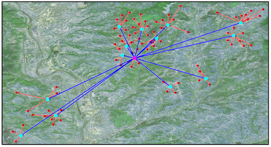
Figure 18.
Design result for star–star pipeline network layout.
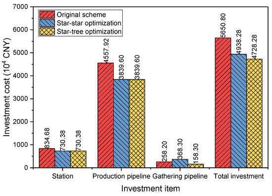
Figure 19.
Investment cost comparison.
5. Conclusions
Academic research on optimizing gas pipeline network layouts has predominantly centered on single-level, single-structure networks, with limited attention given to multi-level and multi-type combined gas pipeline networks. Addressing this gap, this paper establishes a design optimization model for a two-stage star–tree gas-gathering pipeline network in discrete spaces. Recognizing the complexity of the problem and the need for computational efficiency, a hierarchical optimization framework is developed alongside an IGA to effectively solve this optimization problem.
Building upon this model, we determined the optimized design of a star–tree pipeline network for a natural gas field in China, resulting in optimal design outcomes. The findings reveal that the optimized network layout scheme achieves a 16% reduction in investment costs compared to the original scheme, amounting to savings of CNY 922.52×10⁴. Additionally, we compared this optimized layout with a star–star topology. It was observed that adopting the star–star layout would increase the investment cost by 4% compared to the star–tree layout scheme. This comparison underscores the superior applicability of the star–tree topology for this particular network system.
Although the model established in this paper effectively solves the star–tree pipeline network design optimization problem, it still has the following shortcomings: The model does not consider the hydraulic flow characteristics of natural gas, so it cannot effectively judge whether the fluid pressure changes in pipeline network meet the technological requirements. Furthermore, the hierarchical optimization strategy employed in this study does not ensure that the solution obtained is the global optimal solution. Therefore, future research should comprehensively incorporate gas operation characteristics into the pipeline network design optimization model. Additionally, adopting a more systematic global optimization method will be essential to effectively address this challenge.
Author Contributions
Validation, Y.Q.; formal analysis, H.C.; investigation, J.H.; software, P.D.; data curation, D.L.; writing—original draft, Y.L. and J.Z.; writing—review and editing, Y.L. and J.Z. All authors have read and agreed to the published version of the manuscript.
Funding
This research was funded by [the National Natural Science Foundation of China] grant number [51704253].
Data Availability Statement
The data that support the findings of this study are available from the corresponding authors upon reasonable request.
Acknowledgments
The authors gratefully acknowledge the financial support provided by the National Natural Science Foundation of China (51704253) for this project.
Conflicts of Interest
Authors Yu Lin and Yanhua Qiu were employed by the company PetroChina Southwest Oil & Gasfield Company. Author Hao Chen was employed by the company Sichuan Shale Gas Exploration and Development Co., Ltd. Author Dafan Liu was employed by the company CNPC Chuanqing Drilling Engineering Co., Ltd. The remaining authors declare that the research was conducted in the absence of any commercial or financial relationships that could be construed as a potential conflict of interest.
Nomenclature
| Sets | |
| Well set, | |
| Station candidate position set, | |
| Plant candidate position set, | |
| Parameters | |
| Pipeline network investment, CNY | |
| Price of pipeline between wells and stations, CNY/m | |
| Price of pipeline between stations, CNY/m | |
| Maximal allowable pipeline length from well to station, m | |
| Cost of plant, CNY | |
| Cost of station, CNY | |
| Plant investment, CNY | |
| Station investment, CNY | |
| Production pipeline investment, CNY | |
| Gathering pipeline investment, CNY | |
| Pipeline length from wells to stations, m | |
| Pipeline length between stations, m | |
| Node gas flow of station j, m3/d | |
| Capacity of station, m3/d | |
| Node gas flow of well i, m3/d | |
| Node gas flow of plant k, m3/d | |
| Connection decision variable between wells and stations, 0 or 1 | |
| Station location decision variable, 0 or 1 | |
| Connection decision variable between stations, 0 or 1 | |
| Plant location decision variable, 0 or 1 | |
References
- Zhou, J.; Fu, T.; Chen, Y.; Xiao, Y.; Peng, J.; Liang, G. A mixed integer nonlinear programming model for optimal design of natural gas storage surface double-pipe network. J. Energy Storage 2021, 44, 103379. [Google Scholar] [CrossRef]
- Rios-Mercado, R.; Borraz-Sanchez, C. Optimization problems in natural gas transportation systems: A state-of-the-art review. Appl. Energy 2015, 147, 536–555. [Google Scholar] [CrossRef]
- Demissie, A.; Zhu, W.; Belachew, C.T. A multi-objective optimization model for gas pipeline operations. Comput. Chem. Eng. 2017, 100, 94–103. [Google Scholar] [CrossRef]
- Hong, B.; Li, X.; Di, G.; Song, S.; Yu, W.; Chen, S.; Li, Y.; Gong, J. An integrated MILP model for optimal planning of multi-period onshore gas field gathering pipeline system. Comput. Ind. Eng. 2020, 146, 106479. [Google Scholar] [CrossRef]
- Sanaye, S.; Mahmoudimehr, J. Optimal design of a natural gas transmission network layout. Chem. Eng. Res. Des. 2013, 91, 2465–2476. [Google Scholar] [CrossRef]
- Rodriguez, D.A.; Oteiza, P.P.; Brignole, N.B. Simulated Annealing Optimization for Hydrocarbon Pipeline Networks. Ind. Eng. Chem. Res. 2013, 52, 8579–8588. [Google Scholar] [CrossRef]
- Fu, Y.X. Multi-objective parameters optimization design of single-pipe ring-type mixing water oil-gathering pipe network. Key Eng. Mater. 2011, 467, 1285–1290. [Google Scholar] [CrossRef]
- Wang, B.; Yuan, M.; Zhang, H.; Zhao, W.; Liang, Y. An MILP model for optimal design of multi-period natural gas transmission network. Chem. Eng. Res. Des. 2018, 129, 122–131. [Google Scholar] [CrossRef]
- Zhou, J.; Zhou, X.; Liang, G.; Peng, J. An MINLP model for network layout of underground natural gas storage. J. Intell. Fuzzy Syst. 2020, 38, 4619–4642. [Google Scholar] [CrossRef]
- Daskin, M. Network and discrete location models, algorithms and applications. J. Oper. Res. Soc. 1997, 48, 763–764. [Google Scholar] [CrossRef]
- Posta, M.; Ferland, J.A.; Michelon, P. An exact cooperative method for the uncapacitated facility location problem. Math. Program. Comput 2014, 6, 199–231. [Google Scholar] [CrossRef]
- Balinski, M.L. Integer programming: Methods, uses, computations. Manag. Sci. 1965, 12, 253–313. [Google Scholar] [CrossRef]
- Klincewicz, J.G.; Luss, H.; Rosenberg, E. Optimal and heuristic algorithms for multiproduct uncapacitated facility location. Eur. J. Oper. Res. 1986, 26, 251–258. [Google Scholar] [CrossRef]
- Efroymson, M.A.; Ray, T.L. A branch-bound algorithm for plant location. Oper. Res. 1966, 14, 361–368. [Google Scholar] [CrossRef]
- Uester, H.; Dilaveroglu, S. Optimization for design and operation of natural gas transmission networks. Appl. Energy 2014, 133, 56–69. [Google Scholar] [CrossRef]
- Zhang, H.; Liang, Y.; Zhang, W.; Wang, B.; Yan, X.; Liao, Q. A unified MILP model for topological structure of production well gathering pipeline network. J. Pet. Sci. Eng. 2017, 152, 284–293. [Google Scholar] [CrossRef]
- Bosikov, I.I.; Klyuev, R.V.; Silaev, I.V.; Stas, G.V. Comprehensive assessment of formalized ventilation difficultly and technological processes in coal mines. Sustain. Dev. Mt. Territ. 2023, 15, 516–527. [Google Scholar] [CrossRef]
- Nguyen, H.; Bui, X.N.; Choi, Y.; Topal, E. Application of artificial intelligence in predicting slope stability in open-pit mines: A case study with a novel imperialist competitive algorithm-based radial basis function neural network. In Applications of Artificial Intelligence in Mining, Geotechnical and Geoengineering; Elsevier: Amsterdam, The Netherlands, 2024; pp. 97–111. [Google Scholar]
- Rosa, V.R.; Camponogara, E.; Ferreira Filho, V.J.M. Design optimization of oilfield subsea infrastructures with manifold placement and pipeline layout. Comput. Chem. Eng. 2018, 108, 163–178. [Google Scholar] [CrossRef]
- Liu, Y.; Chen, S.; Guan, B.; Xu, P. Layout optimization of large-scale oil-gas gathering system based on combined optimization strategy. Neurocomputing 2019, 332, 159–183. [Google Scholar] [CrossRef]
- Hong, B.; Li, X.; Di, G.; Li, Y.; Liu, X.; Chen, S.; Gong, J. An integrated MILP method for gathering pipeline networks considering hydraulic characteristics. Chem. Eng. Res. Des. 2019, 152, 320–335. [Google Scholar] [CrossRef]
- Montagna, A.F.; Cafaro, D.C.; Grossmann, I.E.; Burch, D.; Shao, Y.; Wu, X.H.; Furman, K. Pipeline network design for gathering unconventional oil and gas production using mathematical optimization. Optim. Eng. 2023, 24, 539–589. [Google Scholar] [CrossRef]
- Slowik, A.; Kwasnicka, H. Evolutionary algorithms and their applications to engineering problems. Neural Comput. Appl. 2020, 32, 12363–12379. [Google Scholar] [CrossRef]
- Tohyama, H.; Ida, K.; Matsueda, J. A genetic algorithm for the uncapacitated facility location problem. Electr. Commun. Jpn. 2011, 94, 47–54. [Google Scholar] [CrossRef]
- Beasley, J.E. OR-Library: Distributing test problems by electronic mail. J. Oper. Res. Soc. 1990, 41, 1069–1072. [Google Scholar] [CrossRef]
- Al-Sultan, K.S.; Hussain, M.F.; Nizami, J.S. A genetic algorithm for the set covering problem. J. Oper. Res. Soc. 1996, 47, 702–709. [Google Scholar] [CrossRef]
- Pettie, S.; Ramachandran, V. An optimal minimum spanning tree algorithm. J. ACM 2002, 49, 16–34. [Google Scholar] [CrossRef]
- Zhou, J.; Peng, J.; Liang, G.; Deng, T. Layout optimization of tree-tree gas pipeline network. J. Pet. Sci. Eng. 2019, 173, 666–680. [Google Scholar] [CrossRef]
Disclaimer/Publisher’s Note: The statements, opinions and data contained in all publications are solely those of the individual author(s) and contributor(s) and not of MDPI and/or the editor(s). MDPI and/or the editor(s) disclaim responsibility for any injury to people or property resulting from any ideas, methods, instructions or products referred to in the content. |
© 2024 by the authors. Licensee MDPI, Basel, Switzerland. This article is an open access article distributed under the terms and conditions of the Creative Commons Attribution (CC BY) license (https://creativecommons.org/licenses/by/4.0/).