Article

Trajectory Classification and Recognition of Planar Mechanisms Based on ResNet18 Network

School of Mechanical and Precision Instrument Engineering, Xi’an University of Technology, Xi’an 710048, China
*
Author to whom correspondence should be addressed.
Algorithms 2024, 17(8), 324; https://doi.org/10.3390/a17080324
Submission received: 31 May 2024 / Revised: 7 July 2024 / Accepted: 15 July 2024 / Published: 25 July 2024

Abstract

:
This study utilizes the ResNet18 network to classify and recognize trajectories of planar mechanisms. This research begins by deriving formulas for trajectory points in various typical planar mechanisms, and the resulting trajectory images are employed as samples for training and testing the network. The classification of trajectory images for both upright and inverted configurations of a planar four-bar linkage is investigated. Compared with AlexNet and VGG16, the ResNet18 model demonstrates superior classification accuracy during testing, coupled with reduced training time and memory consumption. Furthermore, the ResNet18 model is applied to classify trajectory images for six different planar mechanisms in both upright and inverted configurations as well as to identify whether the trajectory images belong to the upright or inverted configuration for each mechanism. The test results affirm the feasibility and effectiveness of the ResNet18 network in the classification and recognition of planar mechanism trajectories.

1. Introduction

Planar linkage mechanisms are widely used in daily life, such as the weft insertion mechanism in knitting machines, wing-folding mechanisms in airplanes, and rehabilitation robots. Among these, trajectory synthesis is a key issue in mechanism design. The trajectory of a planar mechanism refers to the path traced by a specific point during the mechanism’s motion, determined by the mechanism’s structural characteristics and motion conditions. In machines and devices, the trajectory synthesized by the mechanism needs to closely approximate the desired path as much as possible [1]. Moreover, satisfactory results in trajectory synthesis can only be achieved when the type of mechanism to which the trajectory belongs is identified. Therefore, determining the type of mechanism to which a trajectory belongs is of significant importance for enhancing the accuracy of trajectory synthesis.
There are generally three methods for synthesizing planar mechanism trajectories: graphical, analytical [2], and optimization [3,4,5]. Graphical methods are simple and quick but provide lower accuracy solutions, whereas analytical methods offer higher-precision solutions. Optimization methods, on the other hand, do not impose restrictions on the number of coupling points, making them more efficient. Martínez-Alfaro H [6] used a simulated annealing method to optimize trajectory points and synthesize corresponding four-bar mechanisms. Buśkiewicz J [7] constructed an objective function and used evolutionary algorithms to optimize trajectories. Qaiyum A et al. [8] and Sanchez-Marquez A et al. [9] proposed new algorithms based on harmony search to optimize four-bar mechanisms. Zarkandi S proposed a trajectory synthesis for planar four-bar mechanisms based on a gravity search algorithm that minimizes a modified error function [10]. Sharma et al. [11] and Wu R et al. [12] synthesized four-bar mechanisms using the Fourier descriptor method. Daniali H M et al. [13] used a particle swarm optimization algorithm to optimize planar four-bar mechanisms with clearances. Wang B et al. [14] proposed a numerical synthesis program that combines motion generation and function generation for four-bar mechanisms. Han J et al. [15] proposed a solution domain approach for trajectory synthesis of planar four-bar mechanisms with eight precision points, achieving good results. Sun J et al. [16] established a spherical four-bar mechanism database and obtained the most suitable basic dimension types for the mechanism under specified link curves. For trajectory synthesis of five-bar mechanisms, Mundo D et al. [17] proposed an optimization method for non-circular gear five-bar mechanisms, using genetic algorithms to find globally optimal solutions. Russell K et al. [18] used fixed-length constraint equations to synthesize the drive mechanism and the required link parameters. Sun J et al. [19] proposed a method based on wavelet analysis theory and established an adaptive database. Kapsalyamov A et al. [20] proposed a method based on deep generative neural networks to obtain a set of optimal dimensions and parameters for Stephenson-III type six-bar mechanisms. Peón-Escalante R et al. [21] algebraically synthesized Stephenson-III type planar six-bar mechanisms, while Sun J et al. [22] used wavelet series to synthesize planar six-bar mechanisms.
The above-mentioned scholars used different methods to synthesize planar mechanism trajectories, designing corresponding mechanisms to generate curves close to the desired path. However, they did not judge the type of mechanism to which the trajectory belongs, which could lead to synthesized mechanisms not effectively generating the expected curves. Therefore, this paper starts with trajectory images and proposes a method based on the ResNet18 network to determine the type of mechanism to which the trajectory image belongs, aiming to improve the accuracy of subsequent trajectory synthesis.
The remaining content of this paper is as follows: In the second section, the trajectory point formulas for six common planar mechanisms are derived, and the resulting trajectory images are used as training and testing samples. In the third section, the performance of several networks is studied. Then, experiments are conducted in the fourth section. The fifth section summarizes this paper.

2. Sample Construction

As shown in Figure 1, the trajectories generated by a planar four-bar mechanism in regular and inverted configurations with the same parameters are entirely different. Therefore, after determining the mechanism type, it is necessary to distinguish between the regular and inverted installations.
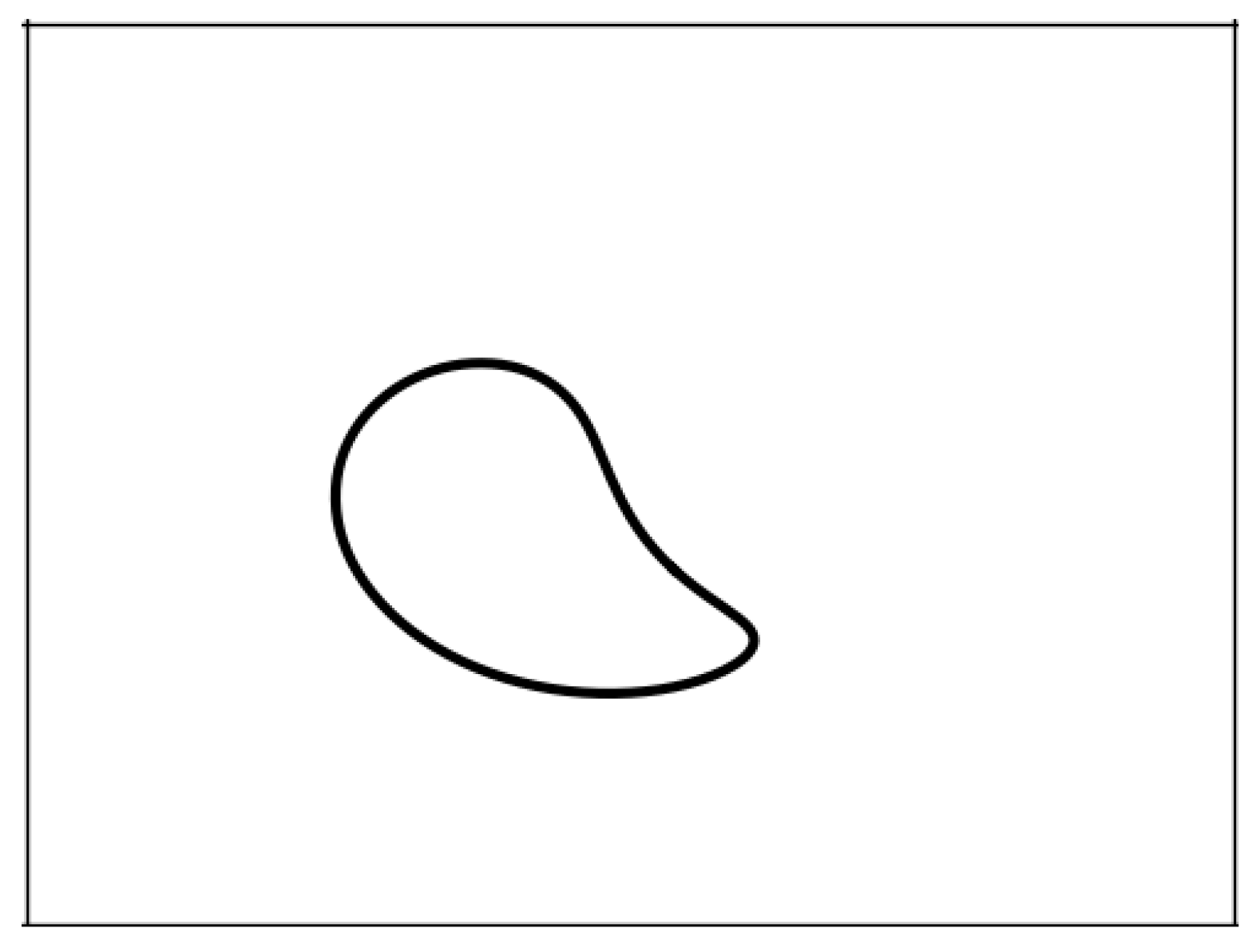
In recent years, deep learning has achieved remarkable success in image recognition and classification tasks, significantly improving accuracy. Therefore, this paper employs a deep learning approach for trajectory classification and recognition. Samples are saved in the form of images, as depicted in Figure 2.
The saved images have a size of 128 × 128 pixels. Before training, data augmentation operations are applied to enhance the network’s generalization performance and robustness, enabling the trained network to handle samples of varying sizes, angles, and brightness. Specifically, the data augmentation operations employed include the following:
(1) A random rotation operation is applied to the samples with rotation angles in the range of [−10°, 10°].
(2) A random horizontal flipping operation is applied to the samples.
(3) Standardization is performed on each channel of the sample images, setting the mean to 0.5 and the standard deviation to 0.5.

2.1. Hinge Four-Bar Mechanism Sample Construction

Four-bar mechanisms are very common, consisting of four links connected by hinges to form a closed mechanism. Due to their simplicity and reliability, they find widespread applications in engineering and the field of mechanics [23].
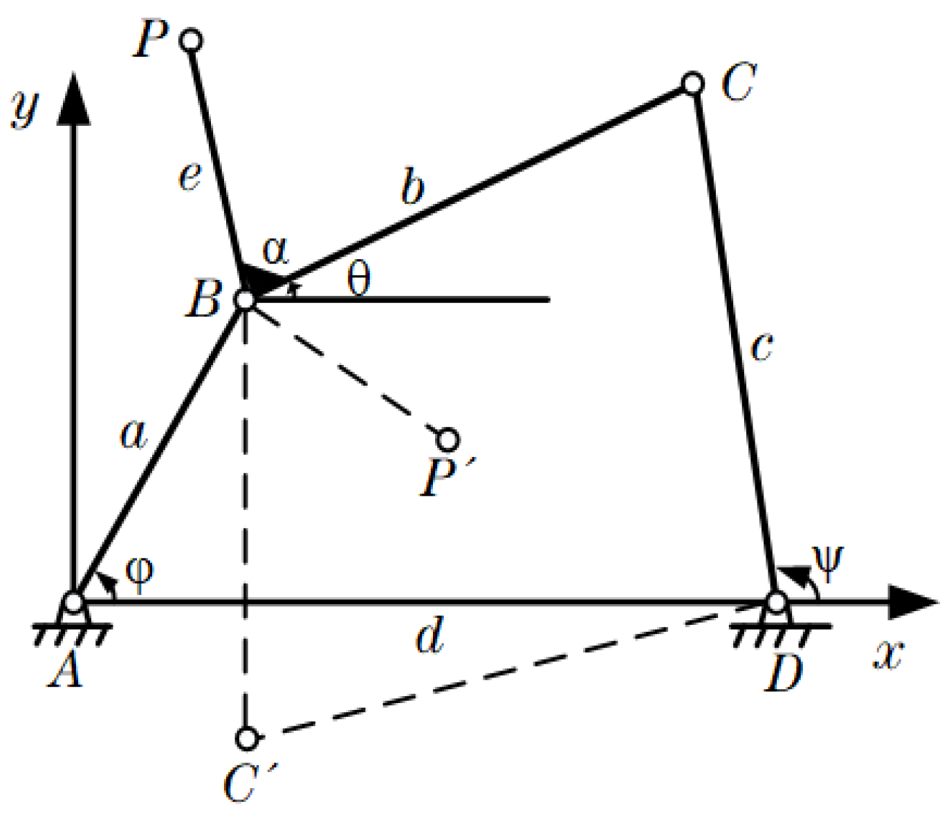
The four-bar mechanism is illustrated in Figure 3, where a , b , c , d , e  represent the length of the corresponding link, α  represents the angle between links BC and BP, and point P is the trajectory point. The solid line in the figure represents the regular configuration, while the dashed line represents the inverted configuration. By varying the values of these six parameters, different four-bar mechanisms can be designed to obtain various trajectory diagrams for the mechanisms.
Based on the parameters of the four-bar mechanism shown in Figure 3, formulate Equation (1) and solve for θ .
a cos φ + b cos θ = d + c cos ψ a sin φ + b sin θ = c sin ψ
The equation is calculated as follows:
θ = 2 tan 1 ( B 0 ± A 0 2 + B 0 2 C 0 2 A 0 + C 0 )
A 0 = 2 b ( a cos φ d )
B 0 = 2 a b sin φ
C 0 = a 2 + b 2 c 2 + d 2 2 a d cos φ
where the positive configuration is denoted by ‘−’ and the inverted configuration is denoted by ‘+’. After solving for  θ , the coordinates of the trajectory point P can be obtained as shown in Equation (2).
x P = a cos φ + e cos ( α + θ ) y P = a sin φ + e sin ( α + θ )
For the design of a planar four-bar mechanism, only the link length conditions need to be considered, requiring that the sum of the shortest link and the longest link be less than or equal to the sum of the other two links, i.e., a + b c + d ;   a + c b + d ; a + d b + c .
When designing a four-bar mechanism and setting values for its parameters, there are no specific constraints on the ranges of each parameter; they just need to satisfy the fundamental conditions for forming a four-bar mechanism. However, to prevent an excessive increase in the number of samples, the ranges of parameters are limited during the design of the planar four-bar mechanism, specifically as follows: 0 < a , b , c , d , e 1 , 0 α 2 π . Once the parameter ranges are determined, the coordinate axis of the image is set to (−3, 3) to ensure that the generated trajectory appears entirely within the image.

2.2. Construction of Samples for Hyperboloid Crank Hinge Five-Bar Mechanism

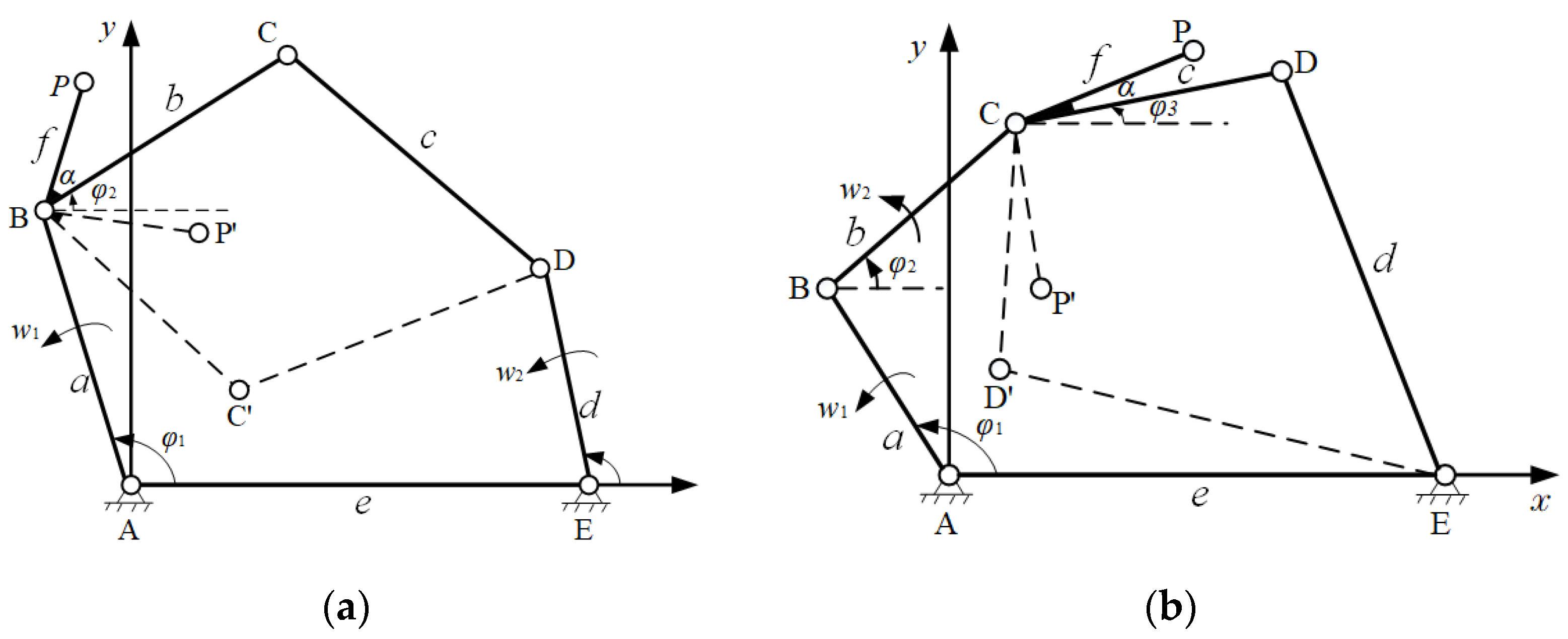
Hinge five-bar mechanisms are two-degree-of-freedom components with complex motion patterns and flexible control characteristics, playing a crucial role in engineering and the field of mechanics. The hyperboloid crank hinge five-bar mechanism, in particular, is widely used for its advantages such as precision in motion and good control performance, making it suitable for a broad range of applications. The structure diagram is shown in Figure 4.
Hinge five-bar mechanisms are two-degree-of-freedom components with complex motion patterns and flexible control characteristics, playing a crucial role in engineering and the field of mechanics. The hyperboloid crank hinge five-bar mechanism, in particular, is widely used for its advantages such as precision in motion and good control performance, making it suitable for a broad range of applications.
The construction of a hyperboloid crank rocker mechanism needs to satisfy the link length scale requirements of classification for Formula (3), i.e., the sum of the two shortest links must be less than or equal to the longest link’s length added to the sum of the other two links.
l m i n 1 + l m i n 2 + l m a x m + n
Planar five-bar mechanisms that satisfy Equation (3) are referred to as Type I mechanisms. Figure 4a,b depict two common Type I mechanisms, known as Class A and Class B. In Class A mechanisms, neither of the two shortest links serves as both the frame and input components, preventing the mechanism from forming a two-crank or three-crank structure. Therefore, the two shortest links cannot function as connecting rods. In Class B mechanisms, one of the two shortest links serves as the frame, or both links can be input components.
For both Class A and Class B five-bar mechanisms, it is necessary to solve for φ 2 and φ 3 , and the solution process is similar to that of four-bar mechanisms.
For Class A mechanisms, the calculation reveals that
φ 2 = 2 tan 1 ( B 0 ± A 0 2 + B 0 2 C 0 2 A 0 + C 0 )
A 0 = 2 b ( e + d cos φ 4 a cos φ 1 )
B 0 = 2 b ( d sin φ 4 a sin φ 1 )
C 0 = b 2 c 2 + e + d cos φ 4 a cos φ 1 2 + ( d sin φ 4 a sin φ 1 ) 2
where the positive configuration is denoted by ‘+’ and the inverted configuration is denoted by ‘−’. So, for Class A mechanisms, the trajectory of point P can be obtained using Equation (4).
x P = a cos φ 1 + f cos ( α + φ 2 ) y P = a sin φ 1 + f sin ( α + φ 2 )
Similarly, for Class B mechanisms, there is
φ 3 = 2 tan 1 ( B 0 ± A 0 2 + B 0 2 C 0 2 A 0 + C 0 )
A 0 = 2 c ( e a cos φ 1 b cos φ 2 )
B 0 = 2 c ( a sin φ 1 b sin φ 2 )
C 0 = ( e a cos φ 1 b cos φ 2 ) 2 + ( a sin φ 1 b sin φ 2 ) 2 + c 2 d 2
So, for Class B mechanisms, the trajectory of point P can be obtained using Equation (5).
x P = a cos φ 1 + b cos φ 2 + f cos ( α + φ 3 ) y P = a sin φ 1 + b sin φ 2 + f sin ( α + φ 3 )
The samples of the hyperboloid crank hinge five-bar mechanism include three classes. When the transmission ratio of the two actuators is 1, the ranges of various parameters are limited to 0 < a , b , c , d , e , f 1 , 0 α 2 π . And the coordinate axis of the image is set to (−3, 3). When the speeds of the two actuators have different ratios, the resulting trajectory images will also be different. In this experiment, we only study the special case where the speed ratio of the two actuators is 1:1. In this case, samples are generated using both Class A and Class B mechanisms.

2.3. Construction of Samples for Single-Loop Hinge Six-Bar Mechanism

The single-loop hinge six-bar mechanism is a mechanism with three degrees of freedom, structurally more complex, and capable of meeting some intricate design tasks. Among them, the structure with three cranks as active components is very common. There are three common types of three-crank single-loop hinge six-bar mechanisms, as shown in Figure 5, referred to as Class A, Class B, and Class C.
For Class A and Class B mechanisms, it is necessary to solve for φ 3 and φ 4 . After derivation, the following formulas are obtained:
φ 3 = 2 tan 1 ( B 0 A 0 2 + B 0 2 C 0 2 A 0 + C 0 )
φ 4 = tan 1 a sin φ 1 + b sin φ 2 + c sin φ 3 e sin φ 5 a cos φ 1 + b cos φ 2 + c cos φ 3 e cos φ 5 f
A 0 = 2 c ( e cos φ 5 f + a cos φ 1 + b cos φ 2 )
B 0 = 2 c ( e sin φ 5 + a sin φ 1 + b sin φ 2 )
C 0 = a 2 + b 2 + c 2 d 2 + e 2 + f 2 + 2 e f cos φ 5 2 a f cos φ 1 2 b f cos φ 2 2 a e cos φ 1 φ 5 + 2 a b cos φ 1 φ 2 2 b e cos ( φ 2 φ 5 )
where the positive configuration is denoted by ‘−’ and the inverted configuration is denoted by ‘+’.
Thus, the coordinates of the trajectory point P in the Class A mechanism can be expressed as shown in Equation (6).
x P = a cos φ 1 + b cos φ 2 + g cos ( α + φ 3 ) y P = a sin φ 1 + b sin φ 2 + g sin ( α + φ 3 )
In the Class B mechanism, the coordinates of the trajectory point P can be expressed as shown in Equation (7).
x P = f + e cos φ 5 + g cos ( φ 4 α ) y P = e sin φ 5 + g sin ( φ 4 α )
Similarly, for the Class C mechanism, it is necessary to solve for φ 4 . After derivation, the following formula is obtained:
φ 4 = 2 tan 1 ( B 0 A 0 2 + B 0 2 C 0 2 A 0 + C 0 )
A 0 = 2 d ( f + a cos φ 1 + b cos φ 2 + c cos φ 3 )
B 0 = 2 d ( a sin φ 1 + b sin φ 2 + c sin φ 3 )
C 0 = a 2 + b 2 + c 2 + d 2 e 2 + f 2 2 c f cos φ 3 2 a f cos φ 1 2 b f cos φ 2 + 2 a c cos φ 1 φ 3 + 2 a b cos φ 1 φ 2 + 2 b e cos ( φ 2 φ 3 )
where the positive configuration is denoted by ‘−’ and the inverted configuration is denoted by ‘+’.
So, for the Class C mechanism, the trajectory of point P is given by Equation (8).
x P = f + e cos φ 5 + g cos ( φ 4 α ) y P = e sin φ 5 + g sin ( φ 4 α )
In the single-loop hinge six-bar mechanisms, Class A and Class B need to satisfy the constraint condition shown in Equation (9), while Class C needs to satisfy the constraint condition shown in Equation (10). In this way, these mechanisms can all meet the link length requirements for six-bar mechanisms and ensure that the three prime movers are all cranks.
c + d a + b + e + f c d m i n { a b e f , b a e f , e a b f , f a b e }
d + e a + b + c + f d e m i n { a b c f , b a c f , c a b f , f a b c }
The samples of the single-loop hinge six-bar mechanism include four classes for regular and inverted configurations. When the transmission ratio of the three actuators is 1, the ranges of various parameters are limited to 0 < a , b , c , d , e , f , g 1,0 α 2 π . The coordinate axis of the image is set to (−3, 3). For the six-bar mechanism with three actuators having a speed ratio of 1:1:1, samples are generated using Class A, Class B, and Class C mechanisms.

3. Selection of the Network

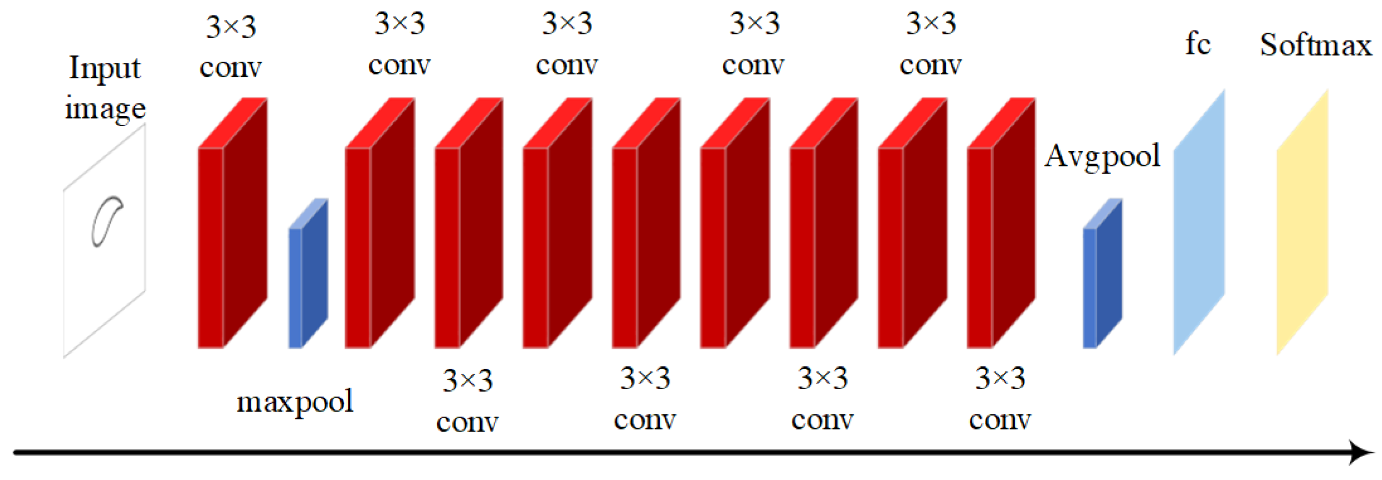
The ResNet18 network is a type of deep convolutional neural network model, commonly used in computer vision, particularly for image classification [24]. The core idea of this network is the introduction of residual blocks, as shown in Figure 6, to address the issues of gradient vanishing and degradation in deep networks.
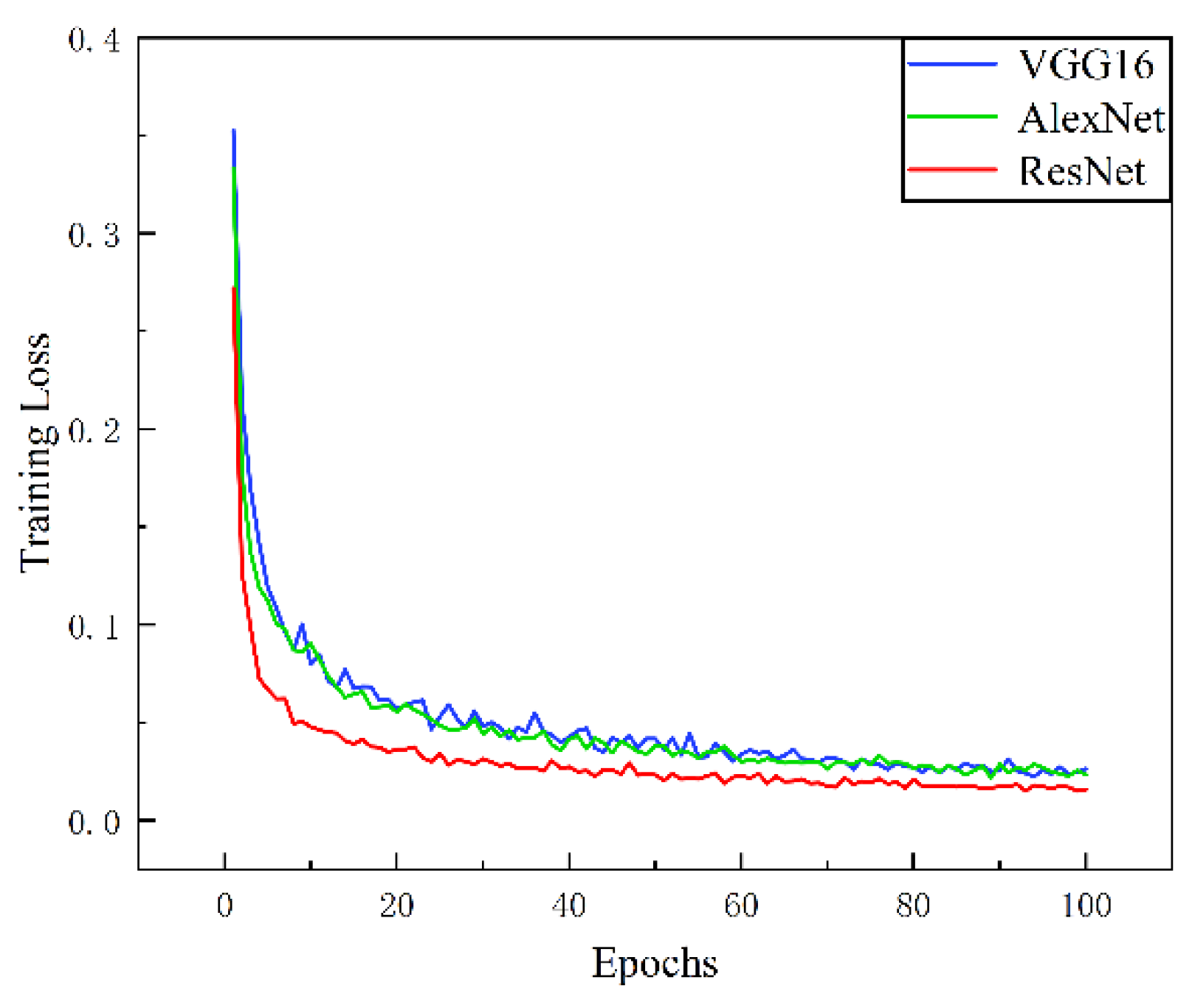
When classifying the trajectories of the planar four-bar mechanism in regular and inverted configurations, multiple image classification networks are used for training. These networks include the AlexNet [25], VGG16 [26], and ResNet18 [27]. Finally, the model is selected based on its classification accuracy and performance. This approach not only ensures that the selected model has higher accuracy but also saves resources during the training process. The training set consists of 10,000 images for both regular and inverted configurations of the planar four-bar mechanism. The loss function is the mean-squared-error loss function, the learning rate is set to 0.001, the optimizer used is the Adam optimizer, the training epoch is 100, and the batch size is set to 8. Using these three different networks, three models are trained, and the training errors are shown in Figure 7. The obtained models are then tested on a test set containing 500 images for both regular and inverted configurations of the planar four-bar mechanism. The results are shown in Table 1.
From Figure 7, it can be observed that with 100 training epochs, the learning training time is shorter and memory usage is lower. Therefore, for the classification of trajectories in other planar mechanisms, the ResNet18 network is chosen for model construction.

4. Training Model

This experiment is divided into two steps: classification of trajectories in regular and inverted configurations for a specific type of mechanism and recognition of trajectories in regular and inverted configurations for another type of mechanism. During training, the batch size is set to 8, the number of epochs is 100, the Adam optimizer is used, the loss function is the mean-squared-error loss function, and the learning rate is set to 0.001.

4.1. Classification of Trajectories in Regular and Inverted Configurations

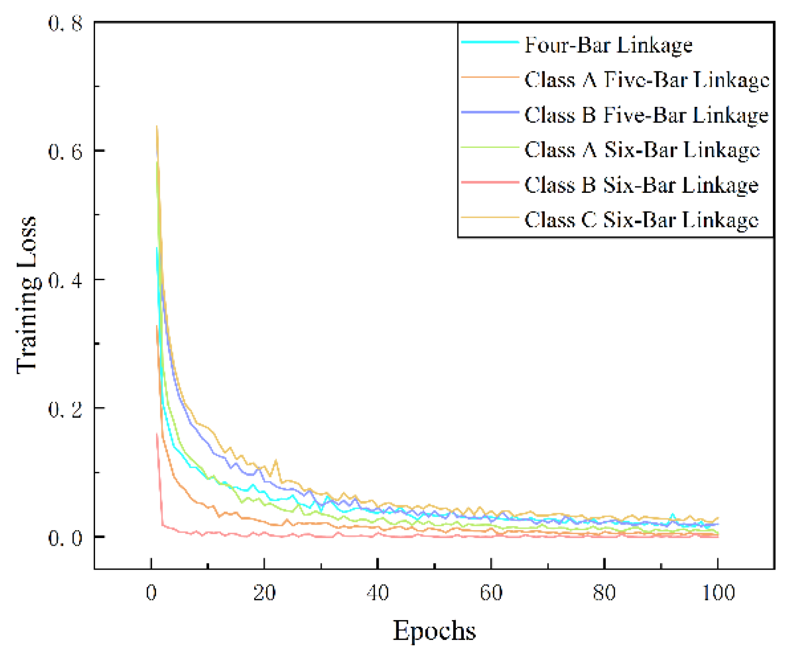
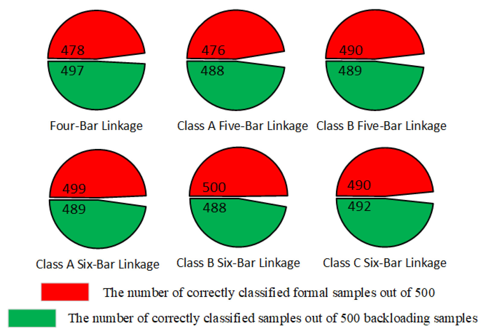
Each type of mechanism is trained with 10,000 samples for both regular and inverted trajectory images, and the test set includes 500 images for both regular and inverted trajectories. The training error and test results using the ResNet18 network are shown in Figure 8 and Figure 9.
In Figure 8, only correctly classified results are shown. However, since the number of test samples is fixed, the problem is essentially a binary classification problem (regular and inverted configurations). Therefore, incorrectly classified images would belong to the other class. For example, trajectory images of Class A planar five-bar mechanisms in regular configuration would only be incorrectly classified as Class A planar five-bar mechanisms in inverted configuration. From Figure 8, it can be observed that during the training process, the error consistently decreases for each type of mechanism. Initially, the error decreases rapidly and then slows down gradually, eventually stabilizing. This indicates that the model has good generalization and robustness. Figure 9 shows that the method achieves high accuracy in classifying mechanisms in the test set, ranging from 96.40% to 98.80%.

4.2. Recognition of Trajectories in Regular and Inverted Configurations

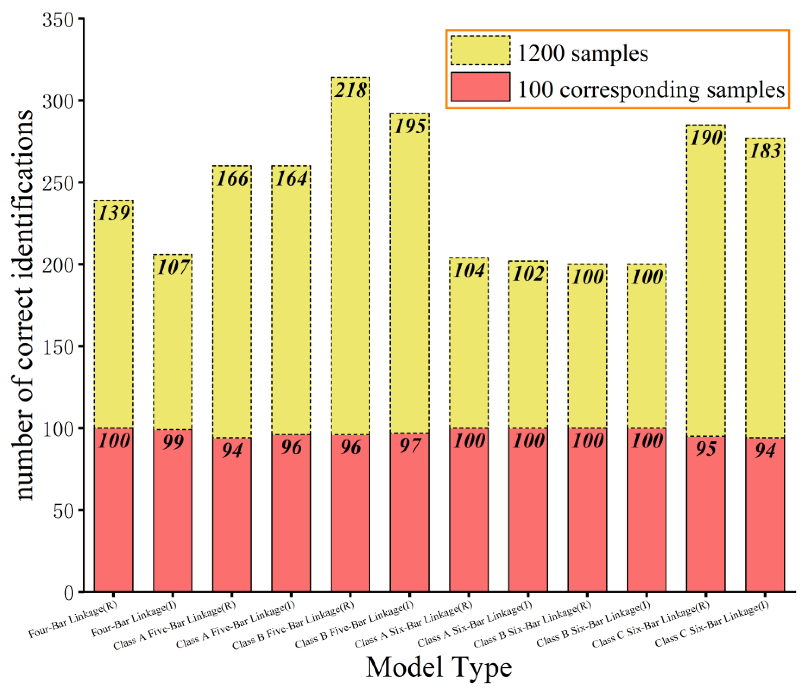
In theory, a trajectory can be generated by mechanisms with different numbers of links. For example, the trajectory of a four-bar mechanism can also be produced by a five-bar mechanism. Therefore, different models are established to recognize the installation methods of different mechanisms, and the construction of the sample set varies. For example, the training set for distinguishing the regular configuration of a four-bar mechanism includes 10,000 images of the regular configuration trajectory of a four-bar mechanism, as well as the inverted configuration trajectory of a four-bar mechanism, the regular configuration trajectory of a five-bar mechanism (Class A), the inverted configuration trajectory of a five-bar mechanism (Class A), the regular configuration trajectory of a five-bar mechanism (Class B), the inverted configuration trajectory of a five-bar mechanism (Class B), the regular configuration trajectory of a six-bar mechanism (Class A), the inverted configuration trajectory of a six-bar mechanism (Class A), the regular configuration trajectory of a six-bar mechanism (Class B), the inverted configuration trajectory of a six-bar mechanism (Class B), the regular configuration trajectory of a six-bar mechanism (Class C), and the inverted configuration trajectory of a six-bar mechanism (Class C), with each category containing 1000 images. Similar training sets are constructed for other categories, resulting in a total of 12 different training sets. The test set consists of 100 images for each installation method in each category, totaling 1200 images. The same test set is used for different models. After 100 epochs of training, the max and min training errors and the test results on the test set were obtained; these are shown in Table 2 and Figure 10.
From Table 2, it can be observed that during the training process of the regular configuration, the inverted configuration of the four-bar mechanism, regular and inverted configurations of the six-bar mechanism (Class A), and regular and inverted configurations of the six-bar mechanism (Class B), the maximum, minimum, and average training errors are significantly smaller than those of other categories. In Figure 10, the red portion indicates that out of 1200 test samples, each model identified the correct number in its corresponding 100 samples. For example, in the test result of the flat four-bar mechanism formal installation recognition network—that is, the first column in the column chart—it can be seen from the figure that there are 100 confirmed flat four-bar mechanism formal installation images in the 1200 test samples, and the network also recognizes these 100 images; so, the accuracy is 100%. The yellow portion represents the number of additional images that each model identified belonging to this type of institution in a sample of 1200. For example, in the third column of the column diagram, the test results of the Class A formal fitting model of the planar five-bar mechanism show that in addition to 94 out of 100 images belonging to the Class A formal fitting of the planar five-bar mechanism, 166 images are also identified in the remaining images that do not belong to it, indicating that the images of other mechanisms can also be drawn by the Class A formal fitting of the planar five-bar mechanism. In summary, in combination with Figure 10, it can be seen that the trained model has a high recognition rate in the respective sample images and also recognizes the track images of its own organization from the track images of other categories of organizations, which also verifies that a track image can be obtained by different categories of organizations.

5. Conclusions

The experiments on the four-bar mechanism samples indicate that, under similar conditions, the ResNet18 network outperforms AlexNet and VGG16 networks in terms of accuracy for classifying the trajectories of regular and inverted configurations of the planar four-bar mechanism. ResNet18 also demonstrates lower time consumption and memory usage. When applied to the classification of trajectories generated by two classes of planar five-bar mechanisms and three classes of planar six-bar mechanisms, the trained models achieve a minimum classification accuracy of 96.40% on the test set. This suggests that the ResNet18 network is suitable for the classification of trajectories for individual mechanism categories and performs exceptionally well.
Using the model for trajectory recognition in a single installation method effectively addresses the challenge of determining the category of a trajectory belonging to different mechanism types. The trained model exhibits excellent performance on the test set, with accuracy ranging from 94% to 100%. Overall, the ResNet18 network employed in this study demonstrates robust recognition capabilities for mechanism trajectories, offering a new perspective for trajectory synthesis.
The method proposed in this paper can classify and recognize trajectory images with high accuracy. Before conducting trajectory synthesis, this method can be used to determine the trajectory image, thereby improving the accuracy of subsequent trajectory synthesis. Therefore, the method has a wide range of applications. It can be used whenever the given trajectory can be expressed in the form of an image, including but not limited to mechanisms with prismatic joints, spatial mechanisms, and others.

Author Contributions

Conceptualization, J.W.; Software, Y.W.; Writing—original draft, B.C.; Visualization, X.J.; Validation, D.P. All authors have read and agreed to the published version of the manuscript.

Funding

This research was funded by National Natural Science Foundation of China grant number 51275408.

Data Availability Statement

The data presented in this study are available on request from the corresponding author. The data are not publicly available due to [In order to adapt to our study, we processed the dataset].

Conflicts of Interest

The authors declare no conflict of interest.

References

  1. Bulatović, R.R.; Đorðević, S.R. Optimal synthesis of a path generator six-bar linkage. J. Mech. Sci. Technol. 2012, 26, 27–40. [Google Scholar] [CrossRef]
  2. Tari, H.; Su, H.-J. Complete Solution to the Eight-Point Path Generation of Slider-Crank Four-Bar Linkages. J. Mech. Des. 2010, 132, 081003. [Google Scholar] [CrossRef]
  3. Sancibrian, R.; Sarabia, E.G.; Sedano, A.; Blanco, J.M. A general method for the optimal synthesis of mechanisms using prescribed instant center positions. Appl. Math. Model. 2016, 40, 6–22. [Google Scholar] [CrossRef]
  4. Lin, W.; Hsiao, K. A new differential evolution algorithm with a combined mutation strategy for optimum synthesis of path-generating four-bar mechanisms. Proc. Inst. Mech. Eng. 2017, 231, 690–705. [Google Scholar] [CrossRef]
  5. Bulatović, R.R.; Miodragović, G.; Bošković, M.S. Modified Krill Herd (MKH) algorithm and its application in dimensional synthesis of a four-bar linkage. Mech. Mach. Theory 2016, 95, 1–21. [Google Scholar] [CrossRef]
  6. Martínez-Alfaro, H. Four-Bar Mechanism Synthesis for n Desired Path Points Using Simulated Annealing; Springer: Berlin/Heidelberg, Germany, 2007; pp. 23–37. [Google Scholar]
  7. Buśkiewicz, J. A method for optimal path synthesis of four-link planar mechanisms. Inverse Probl. Sci. Eng. 2015, 23, 18–50. [Google Scholar] [CrossRef]
  8. Qaiyum, A.; Mohammad, A. A novel approach for optimal synthesis of path generator four-bar planar mechanism using improved harmony search algorithm. Aust. J. Mech. Eng. 2022, 22, 95–108. [Google Scholar] [CrossRef]
  9. Sanchez-Marquez, A.; Vega-Alvarado, E.; Portilla-Flores, E.A.; Mezura-Montes, E. Synthesis of a planar four-bar mechanism for position control using the harmony search algorithm. In Proceedings of the 2014 11th International Conference on Electrical Engineering, Computing Science and Automatic Control (CCE), Ciudad del Carmen, Mexico, 29 September–3 October 2014; Available online: http://ieeexplore.ieee.org/document/6978286/ (accessed on 3 May 2024).
  10. Zarkandi, S. A novel optimization-based method to find multiple solutions for path synthesis of planar four-bar and slider-crank mechanisms. J. Mech. Eng. Sci. 2021, 235, 385–405. [Google Scholar] [CrossRef]
  11. Sharma, S.; Purwar, A.; Ge, Q.J. An Optimal Parametrization Scheme for Path Generation Using Fourier Descriptors for Four-Bar Mechanism Synthesis. J. Comput. Inf. Sci. Eng. 2019, 19, 014501. [Google Scholar] [CrossRef]
  12. Wu, R.; Li, R.; Liang, H.; Ning, F. Mixed synthesis method of motion and path of planar four-bar linkages. Mech. Sci. 2021, 12, 43–49. [Google Scholar] [CrossRef]
  13. Daniali, H.M.; Varedi, S.M.; Dardel, M.; Fathi, A. A novel algorithm for kinematic and dynamic optimal synthesis of planar four-bar mechanisms with joint clearance. J. Mech. Sci. Technol. 2015, 29, 59–65. [Google Scholar] [CrossRef]
  14. Wang, B.; Du, X.; Ding, J.; Dong, Y.; Wang, C.; Liu, X. The Synthesis of Planar Four-Bar Linkage for Mixed Motion and Function Generation. Sensors 2021, 21, 3504. [Google Scholar] [CrossRef] [PubMed]
  15. Han, J.; Liu, W. On the Solution of Eight-Precision-Point Path Synthesis of Planar Four-Bar Mechanisms Based on the Solution Region Methodology. J. Mech. Robot. 2019, 11, 064504. [Google Scholar] [CrossRef]
  16. Sun, J.; Lu, H.; Chu, J. Variable step-size numerical atlas method for path generation of spherical four-bar crank-slider mechanism. Inverse Probl. Sci. Eng. 2015, 23, 256–276. [Google Scholar] [CrossRef]
  17. Mundo, D.; Gatti, G.; Dooner, D.B. Optimized five-bar linkages with non-circular gears for exact path generation. Mech. Mach. Theory 2009, 44, 751–760. [Google Scholar] [CrossRef]
  18. Russell, K.; Sodhi, R.S. Kinematic Synthesis of Planar Five-Bar Mechanisms for Multi-Phase Motion Generation. JSME Int. J. Ser. C 2004, 47, 345–349. [Google Scholar] [CrossRef]
  19. Sun, J.; Xue, N.; Liu, W.; Chu, J. A synthesis method for path generation of a planar five-bar mechanism based on dynamic self-adaptive atlas database. Inverse Probl. Sci. Eng. 2020, 28, 9–32. [Google Scholar] [CrossRef]
  20. Kapsalyamov, A.; Hussain, S.; Brown, N.A.; Goecke, R.; Hayat, M.; Jamwal, P.K. Synthesis of a six-bar mechanism for generating knee and ankle motion trajectories using deep generative neural network. Eng. Appl. Artif. Intell. 2021, 117, 105500. [Google Scholar] [CrossRef]
  21. Peón-Escalante, R.; Jiménez, F.C.; Soberanis, M.E.; Peñuñuri, F. Path generation with dwells in the optimum dimensional synthesis of Stephenson III six-bar mechanisms. Mech. Mach. Theory 2020, 144, 103650. [Google Scholar] [CrossRef]
  22. Sun, J.; Wang, P.; Liu, W.; Chu, J.; Ren, L. Synthesis of multiple tasks of a planar six-bar mechanism by wavelet series. Inverse Probl. Sci. Eng. 2019, 27, 388–406. [Google Scholar] [CrossRef]
  23. Pickard, J.K.; Carretero, J.A.; Merlet, J.-P. Appropriate analysis of the four-bar linkage. Mech. Mach. Theory 2019, 139, 237–250. [Google Scholar] [CrossRef]
  24. Liang, C.M.; Li, Y.W.; Liu, Y.H.; Wen, P.F.; Yang, H. Segmentation and weight prediction of grape ear based on SFNet-ResNet18. Syst. Sci. Control Eng. 2022, 10, 722–732. [Google Scholar] [CrossRef]
  25. Krizhevsky, A.; Sutskever, I.; Hinton, G.E. ImageNet classification with deep convolutional neural networks. Commun. ACM 2017, 60, 84–90. [Google Scholar] [CrossRef]
  26. Simonyan, K.; Zisserman, A. Very Deep Convolutional Networks for Large-Scale Image Recognition. arXiv 2015. [Google Scholar] [CrossRef]
  27. He, K.; Zhang, X.; Ren, S.; Sun, J. Deep Residual Learning for Image Recognition. arXiv 2015. [Google Scholar] [CrossRef]
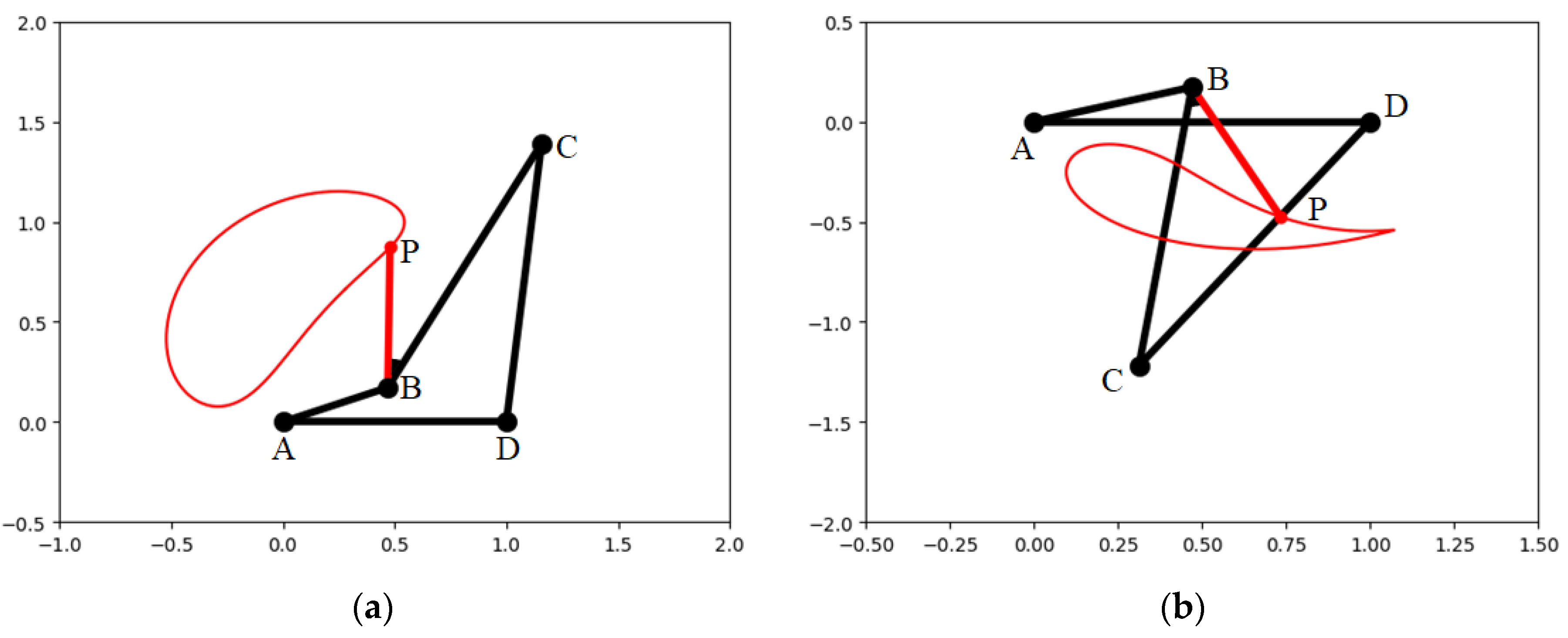
Figure 1. Planar four-bar mechanism positive and negative mounting trajectory diagram. (a) Positive mounting trajectory. (b) Negative mounting trajectory.
Algorithms 17 00324 g001
Figure 2. Trace diagram.
Algorithms 17 00324 g002
Figure 3. Hinge four-bar mechanism model diagram.
Algorithms 17 00324 g003
Figure 4. Hinge five-bar mechanism model diagram. (a) Class A. (b) Class B.
Algorithms 17 00324 g004
Figure 5. Hinge six-bar mechanism model diagram. (a) Class A. (b) Class B. (c) Class C.
Algorithms 17 00324 g005
Figure 6. Residual block diagram.
Algorithms 17 00324 g006
Figure 7. Comparison of three kinds of network training errors.
Algorithms 17 00324 g007
Figure 8. Error diagram of single-class mechanism forward and backward loading classification training.
Algorithms 17 00324 g008
Figure 9. Single-class mechanism classification model test results.
Algorithms 17 00324 g009
Figure 10. Model testing result.
Algorithms 17 00324 g010
Table 1. Three model test results table.
SamplePredicted ResultsAlexNetVGG16 ResNet18
Regular configurationsRegular487490497
Inverted13103
Inverted configurationsRegular331722
Inverted467479478
Training time (s)12,01241,64211,423
Memory (MB)222.7524.543.7
Accuracy rating95.4%96.3%97.5%
Table 2. Single installation classification model training loss table.
Model ClassMax LossMin LossAverage Loss
Four-Bar LinkageRegular0.275640.006720.03224
Inverted0.303650.017740.04257
Class A Five-Bar LinkageRegular0.548370.087410.19721
Inverted0.551850.098540.19836
Class B Five-Bar LinkageRegular0.536490.142650.20871
Inverted0.548550.143540.21043
Class A Six-Bar LinkageRegular0.327020.143540.02249
Inverted0.318860.003700.02016
Class A Six-Bar LinkageRegular0.259020.003870.01447
Inverted0.249520.001730.01386
Class A Six-Bar LinkageRegular0.461310.136630.19283
Inverted0.470590.137430.19212
Disclaimer/Publisher’s Note: The statements, opinions and data contained in all publications are solely those of the individual author(s) and contributor(s) and not of MDPI and/or the editor(s). MDPI and/or the editor(s) disclaim responsibility for any injury to people or property resulting from any ideas, methods, instructions or products referred to in the content.