Article

Data-Driven Load Frequency Control for Multi-Area Power System Based on Switching Method under Cyber Attacks

1
School of Intelligent Engineering, Huanghe Jiaotong University, Jiaozuo 454950, China
2
School of Electrical Engineering and Automation, Henan Polytechnic University, Jiaozuo 454000, China
*
Author to whom correspondence should be addressed.
Algorithms 2024, 17(6), 233; https://doi.org/10.3390/a17060233
Submission received: 28 April 2024 / Revised: 23 May 2024 / Accepted: 24 May 2024 / Published: 27 May 2024

Abstract

:
This paper introduces an innovative method for load frequency control (LFC) in multi-area interconnected power systems vulnerable to denial-of-service (DoS) attacks. The system is modeled as a switching system with two subsystems, and an adaptive control algorithm is developed. Initially, a dynamic linear data model is used to model each subsystem. Next, a model-free adaptive control strategy is introduced to maintain frequency stability in the multi-area interconnected power system, even during DoS attacks. A rigorous stability analysis of the power system is performed, and the effectiveness of the proposed approach is demonstrated by applying it to a three-area interconnected power system.

1. Introduction

The power system, a critical component of national infrastructure, provides stable and reliable electrical energy services to diverse socio-economic sectors. It plays a crucial role in driving modernization and serves as a safeguard for it. The system’s stability, quality, and safety significantly impact national energy security, living standards, and sustainable development. Operational disruptions due to unexpected events and uncertainties can cause frequency deviations from the nominal value in the system. Prolonged frequency deviations not only affect user experience and damage system equipment but can also trigger grid collapse, leading to widespread power outages and significant societal losses. Extensive research has focused on improving the reliable and stable operation of power systems through the study of LFC methods. This research aims to identify more effective frequency control strategies to improve the economic and safety aspects of power systems [1].
Recently, the academic community has proposed diverse control strategies for LFC in multi-area power systems, employing various theoretical frameworks. These strategies encompass Model Predictive Control [2,3], Robust Control [4,5], Fuzzy Logic Control [6,7,8], Sliding Mode Control [9,10], Linear Matrix Inequality (LMI) Control [11,12], Reinforcement Learning [13,14], and other methods. Reference [2] integrates dynamic event-triggered mechanisms and a hybrid H2 performance index to design a robust Model Predictive Control (MPC) strategy for LFC in power systems, capable of effectively handling network attacks and disturbances. Reference [3] introduces a novel dynamic event-based model predictive control strategy designed to enhance the robustness and stability of power system load frequency control in the presence of cyber attacks. Reference [4] designs a robust Proportional-Integral (PI)-type LFC scheme for power systems, taking into account sampling periods and transmission delays in communication networks. Simultaneously, this scheme introduces an Exponential Decay Rate (EDR) as a design parameter. Adjusting the value of EDR can achieve robust performance evaluation regarding parameter uncertainty, load fluctuation, and communication networks. Reference [5] presents a robust LFC strategy for power systems that effectively accounts for transmission delays and varying sampling periods, ensuring improved system stability and performance. Reference [7] presents a sampled memory-event-triggered fuzzy load frequency control method for wind power systems. This approach is specifically designed to address outliers and transmission delays, therefore improving system reliability and performance. Reference [10] introduces a novel sliding model LFC strategy for renewable power systems, addressing time-delay uncertainty, parameter uncertainty, and load disturbances. Subsequently, the sliding mode switching surface and controller are designed based on the standard form. Using the isokinetic convergence law, the system state is directed to reach the switching surface within a finite timeframe, ensuring stable sliding motion on this surface. Reference [11] contributes to power system stability by designing a robust load frequency control (LFC) system capable of coping with inherent time delays by utilizing Linear Matrix Inequalities (LMI). It introduces a novel delay margin estimation technique to ascertain the maximum permissible delay for maintaining system stability, which enhances the control system’s robustness compared to traditional methods. Using brain-inspired deep meta-reinforcement learning, reference [13] enhances multi-area grids’ load frequency control (LFC). This approach develops a fault-tolerant LFC system that adapts to disturbances and faults, showing superior adaptability and robustness compared to traditional methods.
Multi-area interconnected power systems depend on power communication networks for exchanging information and transmitting control commands across regions. Although power communication networks offer advantages like low cost, they also pose new challenges to modern control systems [15]. Reference [16] introduced an advanced LFC strategy for power systems strategically designed to withstand specific categories of DoS attacks. The strategy employs a time-varying Lyapunov function methodology that adapts to the attack parameters’ characteristics, effectively ensuring system stability. Reference [17] explores the application of adaptive dynamic programming-based auxiliary control to a particular class of discrete-time networked systems. Reference [18] explores resilient load frequency control of power systems, addressing random time delays and time-delay attacks. The proposed approach allows practical adjustments for real power systems, balancing accuracy and computational efficiency while considering communication delays. Reference [19] explores the delay-dependent stability of load frequency control under conditions of adjustable computation accuracy and complexity. The researchers propose a novel tuning scheme with adjustable conservatism and computational complexity. Reference [20] focuses on event-triggered load frequency control for power systems, specifically considering limited communication bandwidth. The approach aligns with control performance standards, ensuring stability and efficiency in the presence of communication constraints. The LFC scheme, based on the theory of switched systems in [21], effectively mitigates the DoS attacks’ effects in open communication networks. It calculates the maximum duration and frequency of potential attacks the system can endure and devises a load frequency control strategy for mitigating denial-of-service attacks. This strategy utilizes a dual-loop communication channel and PI controller.
Constructing an accurate mathematical model for power systems remains challenging due to their highly nonlinear and uncertain dynamic characteristics. Therefore, designing model-independent load frequency controllers is crucial. Model-free adaptive control, a data-driven algorithm, directly designs and analyzes controllers using input-output data from the controlled system. This approach enables parameter adaptation and structural adjustments for unknown nonlinear control systems and has found applications in various fields [22,23]. Reference [24] introduced a model-free adaptive quasi-sliding mode control algorithm grounded in a data-driven approach. This algorithm effectively handles nonuniformly sampled nonlinear systems, mitigates the impact of external disturbances, and enhances the system’s robustness and stability. Additionally, the LFC scheme was developed for power systems in [25], using an event-triggered and data-driven approach. However, to our knowledge, there have been limited discussions on MFAC methods for power systems based on switching systems. In this study, we investigate the model-free adaptive LFC method according to switching systems for multi-area power systems under denial-of-service attacks. We conceptualize the multi-area power system under DoS attacks as a switching system composed of two subsystems. We design a switching model-free adaptive controller (SSMFAC) based on this system and use the Lyapunov theory to demonstrate system stability. Finally, we validate the effectiveness of this approach using a three-area interconnected power system. The main contributions of this paper are summarized as follows:
(1)
In this paper, a data-driven load frequency control algorithm based on the switching method is proposed for a multi-area interconnected power system under DoS attack. A switching system model with two subsystems is established to represent the power system under a DoS attack with multi-area interconnection. On this basis, an MFAC algorithm for the switching system is designed.
(2)
In this paper, an event-triggered MFAC is developed for the LFC, and the proposed design alleviates the communication and computation burden of the system compared to existing model-free adaptive control (MFAC) methods in the reference [22]. In addition, existing MFAC system stability analyses use the shrinkage mapping technique tool. However, in this paper, stability analysis is given using the Lyapunov theory approach.

2. Problfm Formulation

2.1. Power System Model

Interconnected power systems comprise multiple regions interconnected via tie lines. Frequency variations in one region can affect neighboring regions through propagation. To keep frequency and tie-line power deviations within specified limits, we term the overall output signal of each control system the Area Control Error (ACE):
ACE i = β i Δ f i + Δ P t i e i
where β i represents the frequency deviation factor, β i = 1 / R i + D i , and D i denote the generator damping coefficients, and R i corresponds to the bias coefficient. The linear model representing interconnected power systems was introduced in reference [14]. The dynamic behavior of this model is described by the following equations:
Δ f ˙ i ( t ) = 1 M i Δ P m i ( t ) Δ P d i ( t ) Δ P t i e i ( t ) D i Δ f i ( t ) Δ P ˙ m i ( t ) = 1 T c h i Δ P v i ( t ) Δ P m i ( t ) Δ P ˙ g i ( t ) = 1 T g i Δ P c i ( t ) 1 R i Δ f i ( t ) Δ P v i ( t ) Δ P ˙ t i e ( t ) = 2 π j = 1 , j i n T i j Δ f i ( t ) Δ f j ( t )
The relevant parameters and associated signals in the equation are defined as shown in Table 1.
Defining x i ( t ) = Δ f i Δ P m i Δ P g i Δ E i Δ P t i e i ,   y i ( t ) = A C E i ( t ) , and u i ( t ) = Δ P c i ( t ) as system inputs, and ϑ i T ( t ) = Δ P d i ( t ) j = 1 , j i N T i j Δ f j ( t ) as the disturbance vector, the dynamic model (1) can be transformed into the following state-space equation:
x ˙ ( t ) = A x ( t ) + B u ( t ) + F ϑ ( t ) y ( t ) = C x ( t )
where
x ( t ) = x 1 ( t ) x 2 ( t ) x N ( t ) T , y ( t ) = y 1 ( t ) y 2 ( t ) y N ( t ) T , u ( t ) = u 1 ( t ) u 2 ( t ) u N ( t ) T , Δ P d ( t ) = Δ P d 1 ( t ) Δ P d 2 ( t ) Δ P dN ( t ) T ,
A = A 11 A 12 A 1 N A 21 A 22 A 2 N A N 1 A N 2 A NN , B = diag B 1 B 2 B N ,
C = diag C 1 C 2 C N F = diag F 1 F 2 F N .
The state and matrix representation of the region are as follows:
A ii = D i M i 1 M i 0 0 1 M i 0 1 T c h i 1 T c h i 0 0 1 R T g i 0 1 T g i 0 0 β i 0 0 0 1 2 π j = 1 , j i n T i j 0 0 0 0 ,   A ij = 0 0 0 0 0 0 0 0 0 0 0 0 0 0 0 0 0 0 0 0 2 π T i j 0 0 0 0
B i = 0 0 1 T g i 0 0 T ,   C i = 0 0 0 0 1 β i 1 0 0 0 F i = 1 M i 0 0 0 0 T ,
To accurately represent the operational behavior of power systems, this research employs a discretization process on the continuous state-space equation. Given a specific sampling period T, the discrete representation of the power system model is articulated as follows:
x ( k + 1 ) = G x ( k ) + H u ( k ) + W ϑ ( k ) y ( k ) = C x ( k )
in the equation, the variable k is formally defined as the discrete-time point used for sampling within the system, and G = e A T ,   H = 0 T e A t B d t ,   W = 0 T e A t F d t , represents unknown matrices.

2.2. Modeling of LFC System under DoS Attacks

DoS attacks are common network attacks targeting power systems. These attacks disrupt communication links within the grid, severing information exchange among internal components and obstructing the transmission of sensor measurement data and control commands over network channels. Significantly, DoS attacks do not require prior or extensive familiarity with the physical power system or grid topology. These attacks can be periodic or intermittent. Consequently, DoS attacks are regarded as low-cost, high-impact attack strategies that real-world adversaries can exploit to compromise critical data transmitted across communication networks.
Subsequently, we model DoS attacks using random variables following the Bernoulli distribution:
Pr { α ( k ) = 2 } = E { α ( k ) } = α Pr { α ( k ) = 1 } = 1 E { α ( k ) } = 1 α
here, we use the Bernoulli distribution to model the distribution of random variables associated with DoS attacks where α ( 0 , 1 ) , when α ( k ) = 2 , indicates that DoS attacks have occurred.
In this context, an on-off signal is introduced as a means to depict two distinct attack scenarios.
α ( k ) = 1 u ( k ) = u ( k ) 2 u ( k ) = u ( k 1 )
In the context of DoS attacks, the hybrid power system in each region can be represented by i switching system α ( k ) ( α ( k ) = 1 , 2 ) :
x ¯ ( k ) = A ¯ x ¯ ( k ) + B ¯ u ¯ α ( k ) ( k ) + F ¯ ϑ ( k ) y ( k ) = C ¯ x ¯ ( k )
where u ¯ 1 ( k ) = u ( k ) ,   u ¯ 2 ( k ) = u ( k 1 ) ,   A ¯ = G ,   B ¯ = H ,   F ¯ = W .
Each subsystem can be represented by the following model:
x ¯ α ( k ) ( k + 1 ) = A ¯ x ¯ α ( k ) ( k ) + B ¯ u ¯ α ( k ) ( k ) + F ¯ ϑ ( k ) y α ( k ) ( k ) = C ¯ x ¯ α ( k ) ( k )

2.3. Dynamic Linearization Scheme

From a holistic perspective, considering the impact of governor dead zones and physical limitations, the power system can be characterized as a profoundly intricate nonlinear system. The LFC subsystem model (7) can be redefined as a comprehensive nonlinear function:
y ( k + 1 ) = f α ( k ) y ( k ) , u ( k )
In the equation, f α ( k ) ( · ) denotes an unknown nonlinear function. Before linearizing the nonlinear power system, we establish the following two assumptions.
Assumption 1. 
The partial derivative of f α ( k ) ( · ) with respect to the variable u ( k ) is continuous at any given sampling instant k.
Assumption 2. 
The nonlinear system (8) adheres to the generalized Lipschitz condition, which implies that for all instances of k > 0 and Δ u ( k ) 0 , the following condition is met:
Δ y ( k + 1 ) b Δ u ( k )
where Δ y ( k + 1 ) = y ( k + 1 ) y ( k ) ,   Δ u ( k ) = u ( k ) u ( k 1 ) ,   b > 0 is a constant.
Remark 1. 
From a practical standpoint, the two assumptions above on the power system (3) are both reasonable and fulfilled. Assumption 1 is a common restriction for a general nonlinear system and the continuity of f α ( k ) · can be inferred from Equation (3). Assumption 2 restricts the maximum pace at which the system output can vary. If the change in Δ P c i is limited, the change in output energy ACE i generated by the power system is also limited, from an energy utilization standpoint.
Theorem 1. 
For subsystems (7) meeting Assumptions 1 and 2, under the condition Δ u ( k ) 0 , there exists a time-varying model called the parameter pseudo-partial derivative (PPD). This parameter ensures that the nonlinear power subsystem model is equivalent to the following compact form dynamic linearization (CFDL) data equations:
Δ y ( k + 1 ) = ϕ α ( k ) ( k ) Δ u ( k )
The parameter ϕ α ( k ) ( k ) is defined as time-varying and remains bounded at every instant.

3. Controller Design

Consider the following input performance index:
J ( u ( k ) ) = y d ( k + 1 ) y ( k + 1 ) 2 + λ α ( k ) | u ( k ) u ( k 1 ) | 2
where λ α ( k ) > 0 represents the weight factor, and y d ( k + 1 ) correlates with the targeted or intended system output.
Substituting Equation (10) into the performance index (11), set the derivative of (11) with respect to u ( k ) be zero:
u ( k ) = u ( k 1 ) + ρ α ( k ) ϕ α ( k ) ( k ) λ α ( k ) + ϕ α ( k ) ( k ) 2 y d ( k + 1 ) y ( k )
in this context, the symbol ρ α ( k ) shows the factor of step size, ρ α ( k ) ( 0 , 1 ] .
Next, to estimate the parameter ϕ α ( k ) ( k ) , we design the following performance index:
J ϕ α ( k ) ( k ) = Δ y ( k ) ϕ α ( k ) ( k ) Δ u ( k 1 ) 2 + μ α ( k ) ϕ α ( k ) ( k ) ϕ ^ α ( k ) ( k 1 ) 2
where ϕ ^ α ( k ) ( k ) represents the estimate of ϕ α ( k ) ( k ) , and μ α ( k ) > 0 is a weighting coefficient.
Minimizing the performance index (13), we obtain the following PPD estimation algorithm:
ϕ ^ α ( k ) ( k ) = ϕ ^ α ( k ) ( k 1 ) + η α ( k ) Δ u ( k 1 ) μ α ( k ) + Δ u 2 ( k 1 ) × Δ y ( k ) ϕ ^ α ( k ) ( k 1 ) Δ u ( k 1 )
where η α ( k ) ( k ) denote step size factor.
To broaden the applicability of the PPD estimation algorithm (14), we incorporate the following reset algorithm:
ϕ ^ α ( k ) ( k ) = ϕ ^ α ( k ) ( 1 ) if θ ^ α ( k ) ( k ) ε or sign ϕ ^ α ( k ) ( k ) sign ϕ ^ α ( k ) ( 1 )
where ε > 0 is a small constant.
ϕ ^ α ( k ) ( k ) = ϕ ^ α ( k ) ( k 1 ) + η α ( k ) Δ u ( k 1 ) μ α ( k ) + Δ u 2 ( k 1 ) × Δ y ( k ) ϕ ^ α ( k ) ( k 1 ) Δ u ( k 1 )
ϕ ^ α ( k ) ( k ) = ϕ ^ α ( k ) ( 1 ) , if ϕ ^ α ( k ) ( k ) ε , or sign ϕ ^ α ( k ) ( k ) sign ϕ ^ α ( k ) ( 1 )
u ( k ) = u ( k 1 ) + ρ α ( k ) ϕ ^ α ( k ) ( k ) λ α ( k ) + ϕ ^ α ( k ) ( k ) 2 y d ( k + 1 ) y ( k )
In this section, we design an event-triggered, data-driven LFC strategy to conserve valuable bandwidth resources. The decision to transmit the most recent sampled data to the corresponding SSMFAC controller will be based on the following triggering conditions:
k r + 1 = k r + min r k r N + r k r e k r T Ω e k r δ
where e k r = y k r y ( k ) represents the triggering error, k r is an integer denoting the triggering instant, and δ is the triggering threshold parameter.
Combining algorithms (16)–(18), we obtain the following event-triggered SSMFAC algorithm:
ϕ ^ α ( k ) ( k ) = ϕ ^ α ( k ) k r 1 + η α ( k ) Δ u ( k 1 ) μ α ( k ) + Δ u 2 ( k 1 ) × Δ y ( k ) ϕ ^ α ( k ) ( k 1 ) Δ u ( k 1 ) k = k r = ϕ ^ α ( k ) k r 1 k k r 1 , k r
ϕ ^ α ( k ) ( k ) = ϕ ^ α ( k ) ( 1 ) , if ϕ ^ α ( k ) ( k ) ε , or sign ϕ ^ α ( k ) ( k ) sign ϕ ^ α ( k ) ( 1 )
u ( k ) = u k r 1 + ρ α ( k ) ϕ ^ α ( k ) ( k ) λ α ( k ) + ϕ ^ α ( k ) ( k ) 2 × y d ( k + 1 ) y k r k = k r u k r 1 k k r 1 , k r
The schematic diagram of SSMFAC is shown in Figure 1.

4. Convergence Analysis

Theorem 2. 
Considering the switched multi-area power system represented by Equation (7), which complies with Assumptions 1 and 2, with respect to j , l and when j l , employing the switching system model-free adaptive controller scheme (20)–(22), given positive scalars o 1 , o 2 , if there exist η i , μ i , ρ i , and λ i such that:
= Ξ 1 Ξ 2 Ξ 3 < 0
where Ξ 1 = 1 o 1 Q i 1 o 1 Q i 1 o 1 Q i o 2 o 2 Q i o 2 Ω , Ξ 2 = diag δ 1 2 ,   δ 1 2 , Ξ 3 = diag { I , I } . The tracking error e ( k ) of the switched multi-area power system (7) is bounded.
Proof of Theorem 2. 
If the conditions of the reset algorithm (17) are met, it becomes clear that the parameter ϕ ^ α ( k ) ( k ) is bounded. Let ϕ ˜ α ( k ) ( k ) = ϕ ^ α ( k ) ( k ) ϕ α ( k ) ( k ) represent the PDD estimation error. By subtracting ϕ α ( k ) ( k ) from both sides of the parameter estimation algorithm (20), we obtain:
ϕ ˜ α ( k ) ( k ) = 1 η α ( k ) Δ u 2 ( k 1 ) μ α ( k ) + Δ u 2 ( k 1 ) ϕ ˜ α ( k ) ( k 1 ) + ϕ α ( k ) ( k 1 ) ϕ α ( k ) ( k )
Obtaining the absolute value of Equation (24), we find:
ϕ ˜ α ( k ) ( k ) = 1 η α ( k ) Δ u 2 ( k 1 ) μ α ( k ) + Δ u ( k 1 ) ϕ ˜ α ( k ) ( k 1 ) + ϕ α ( k ) ( k 1 ) ϕ α ( k ) ( k )
Since ϕ α ( k ) ( k ) d 1 is bounded, there exists ϕ α ( k ) ( k 1 ) ϕ α ( k ) ( k ) 2 d 1 Choosing μ α ( k ) > 0 ,   0 < η α ( k ) < 1 , we can derive η α ( k ) Δ u 2 ( k 1 ) < Δ u 2 ( k 1 ) < μ α ( k ) + Δ u 2 ( k 1 ) . Consequently, there must exist γ constant y such that:
0 < γ < η α ( k ) Δ u 2 ( k 1 ) μ α ( k ) + Δ u 2 ( k 1 ) < 1
Substituting Equation (26) into Equation (25), we obtain:
ϕ ˜ α ( k ) ( k ) ( 1 γ ) ϕ ˜ α ( k ) ( k 1 ) + 2 d 1 ( 1 γ ) 2 ϕ ˜ α ( k ) ( k 2 ) + 2 d 1 ( 1 γ ) + 2 d 1 ( 1 γ ) k 1 ϕ ˜ α ( k ) ( 1 ) + 2 d 1 γ
Therefore, Equation (27) is bounded, and since ϕ ˜ α ( k ) ( k ) is bounded, ϕ ^ α ( k ) ( k ) is also bounded.
The boundedness of tracking error.
We define the system’s tracking error as:
e ( k ) = y d ( k ) y ( k )
By substituting Equations (19) and (13) into Equation (29), we obtain:
e ( k + 1 ) = y d ( k + 1 ) y ( k + 1 ) = y d ( k + 1 ) y ( k ) ϕ α ( k ) ( k ) Δ u ( k ) = e ( k ) ρ α ( k ) ϕ ^ α ( k ) ( k ) ϕ α ( k ) ( k ) λ α ( k ) + ϕ ^ α ( k ) ( k ) 2 e ( k ) e k r = ( 1 Θ ( k ) ) e ( k ) + Θ ( k ) e k r
where Θ ( k ) = ρ α ( k ) ϕ ^ α ( k ) ( k ) ϕ α ( k ) ( k ) λ α ( k ) + ϕ ^ α ( k ) ( k ) 2
Next, consider the following Lyapunov function:
V ( k ) = V α ( k ) ( e ( k ) ) = e T ( k ) Q α ( k ) e ( k )
For the i th subsystem:
V i ( e ( k ) ) = e T ( k ) Q i e ( k )
Let Δ V i ( k + 1 ) = V i ( k + 1 ) V i ( k ) to obtain
Δ V i ( k + 1 ) = ( 1 Θ ( k ) ) e ( k ) + Θ ( k ) e r ( k ) T Q i ( 1 Θ ( k ) ) e ( k ) + Θ ( k ) e r ( k ) e T ( k ) Q i e ( k ) = T ( k ) Λ ( k )
where ( k ) = e ( k ) e k r ,   Λ = 1 2 3 ,   1 = ( 1 Θ ( k ) ) Q i ( 1 Θ ( k ) ) Q i ,   2 = ( 1 Θ ( k ) ) Q i Θ ( k ) , 3 = Θ ( k ) Q i Θ ( k ) .
Let λ min = b 2 / 4 , using the inequality a 2 + b 2 2 a b , we choose λ > λ min such that there exists a constant 0 < M < 1 satisfying:
0 < M ϕ α ( k ) ( k ) ϕ ^ α ( k ) ( k ) λ α ( k ) + ϕ ^ α ( k ) ( k ) 2 b ϕ ^ α ( k ) ( k ) λ α ( k ) + ϕ ^ α ( k ) ( k ) 2 b 2 λ min = 1
consequently, can have o 1 < Θ ( k ) < o 2 .
Let us consider the event-triggered scheme (19) can have:
Δ V i ( k + 1 ) T ( k ) Λ ( k ) + δ e k r T Ω e k r
By utilizing the Schur complement lemma and combining it with Equation (34), have:
Δ V i ( k + 1 ) T ( k ) ( k ) ( k ) < 0
where = Ξ 1 Ξ 2 Ξ 3 , Ξ 1 = 1 o 1 Q i 1 o 1 Q i 1 o 1 Q i o 2 o 2 Q i o 2 Ω , Ξ 2 = diag δ 1 2 ,   δ 1 2 , Ξ 3 = diag { I , I } .
The analysis demonstrates that V i ( k + 1 ) is constrained within a certain range, indicating that the tracking error e ( k ) is similarly bounded. In summary, the tracking error remains within certain bounds, ensuring stable system behavior.
The output y ( k ) is bounded because y d ( k ) is constant and the tracking error e ( k ) converges. □

5. Simulation Example

To validate the effectiveness of the proposed load frequency control scheme based on switched systems, this study employs a three-area interconnected power system as the simulation model. The system parameters are derived from data in reference [15] and are provided in Table 2. The total sampling time is denoted by 60 s , with a sampling period of T = 0.001 s . Other parameters include T 12 = 0.21 ,   T 13 = 0.24 ,   T 23 = 0.13 .
Assuming a data transmission success rate of E { α ( k ) } = 0.6 , the controller parameters are denoted by η 1 = 0.3 ,   η 2 = 0.5 ,   μ 1 = 1.4 ,   μ 2 = 1.2 ,   ρ 1 = 2.5 ,   ρ 2 = 2.8 ,   λ 1 = 1.2 ,   λ 2 = 2.7 , Ω = 10 16 , δ = 0.003 and the initial responses for the three regions are represented by u j ( 1 ) = 0 ,   ϕ ^ j ( 1 ) = 0.3 .
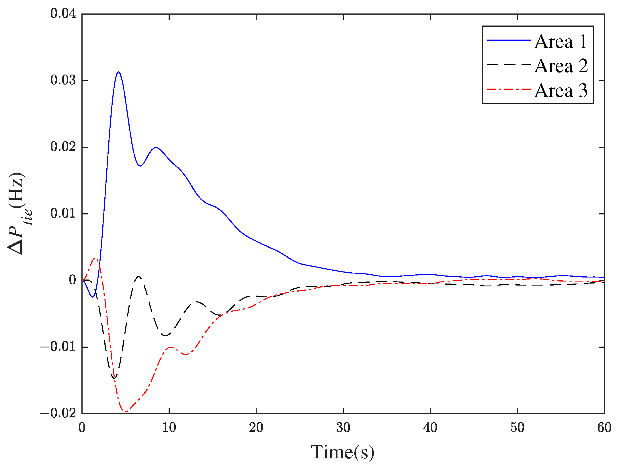
Furthermore, a load disturbance of 0.02 per unit (p.u.) is introduced simultaneously in each region. The system frequency deviation curves, tie-line power variation curves, and system output curves are depicted in Figure 2, Figure 3 and Figure 4. Notably, after running for a certain duration, the deviations in frequency and variations in tie-line power within each region eventually diminish to zero. The simulation results demonstrate the favorable control performance of the proposed algorithm. Figure 5 shows the switching signals.
The release times and intervals between sensor outputs are depicted in Figure 6, Figure 7 and Figure 8, with 255,669, 36,389 and 22,658 trigger occurrences among all sample intervals. Additionally, a comparison was made with the PI control method and frequency curves under the PI and SSMFAC control methods have been plotted in Figure 9. Based on the graph analysis, the SSMFAC control strategy demonstrates superior performance compared to the PI control scheme, showcasing smaller overshoot and faster convergence speed. This observation indicates the effectiveness of the SSMFAC approach in achieving better control system performance.
Additionally, we utilized the “tic” and “toc” functions in MATLAB to measure the average running time of the two algorithms, which were 1.734 s and 2.2505 s, respectively. The results indicate that the SSMFAC method offers a low computational burden while ensuring control performance. In Table 3, we evaluated the effectiveness of the proposed approach using two performance criteria: the Integral of Absolute Error (IAE) and the Integral of Time multiplied by Absolute Error (ITAE). We compared the results with those obtained from the ETSSMFAC and PI schemes. The results show that the SSMFAC algorithm proposed in this paper performs better.
While the event-triggered SSFMAC algorithms (20) and (22) have demonstrated effectiveness in theoretical simulations, it is important to consider practical factors that can influence system control. One such factor is the susceptibility to noise; we have incorporated noise into our simulations to evaluate the robustness of the SSFMAC algorithm under realistic conditions. We modeled noise with mean 0 and variance 0.000000003 as Gaussian white noise added to the input signal.
Figure 10 shows that the system remains stable and performs satisfactorily, but the control accuracy is slightly degraded due to noise. Including noise in the simulations highlights the practical challenges the SSFMAC algorithm faces. While the algorithm remains robust under noisy conditions, additional filtering techniques are necessary to maintain control performance. Future work could focus on developing more advanced noise reduction methods and adaptive filtering techniques to further enhance the control system’s robustness.
In the following sections, we replace constant disturbance with variable load disturbance to test whether the proposed algorithm is capable of dealing with the complex working environment. The trajectory of the load power change is shown in Figure 11, and the response curves are drafted in Figure 12. It can be seen that the control scheme designed in this paper still has superior tracking performance, even if the work environment is changeable. Once again, the operating information confirms the effectiveness and practicability of the SSMFAC algorithm.

6. Conclusions

This paper has a new data-driven load frequency control scheme tailored for power systems vulnerable to Denial-of-Service attacks. The method employs an input-output data-driven LFC algorithm, eliminating the need for a precise power system model and thus streamlining controller design. First, the multi-area interconnected power system under DoS attacks is modeled as a switching system consisting of two subsystems. An event-triggered model-free adaptive LFC algorithm is subsequently introduced within the switching system framework to manage load frequency control. The effectiveness of this scheme is demonstrated by applying it to a three-area interconnected power system. Simulation results confirm that the switching-based, model-free adaptive LFC algorithm maintains robust performance even when facing DoS attacks. However, the methodology has certain limitations, including the inherent dependence on data quality, potential computational complexity, and possible stability issues in highly dynamic or noisy environments typically associated with model-free adaptive control approaches.

Author Contributions

Conceptualization, G.T. and F.W.; methodology, G.T. and F.W.; software, G.T. and F.W.; validation, G.T. and F.W.; formal analysis, G.T.; writing—original draft preparation, G.T.; writing—review and editing, G.T. and F.W. All authors have read and agreed to the published version of the manuscript.

Funding

This research received no external funding.

Data Availability Statement

The original contributions presented in the study are included in the article.

Conflicts of Interest

The authors declare no conflict of interest.

References

  1. Bevrani, H.L. Robust power system frequency control. In Robust Power System Frequency Control; Springer: New York, NY, USA, 2014. [Google Scholar]
  2. Liu, Y.Z.; Chen, Y.; Li, M.T. Dynamic Event-Based Model Predictive Load Frequency Control for Power Systems under Cyber Attacks. IEEE Trans. Smart Grid 2021, 12, 715–725. [Google Scholar] [CrossRef]
  3. Tang, X.; Li, Y.; Yang, M.; Wu, Y.; Wen, Y. Adaptive Event-Triggered Model Predictive Load Frequency Control for Power Systems. IEEE Trans. Power Syst. 2023, 38, 4003–4014. [Google Scholar] [CrossRef]
  4. Shangguan, X.C.; Zhang, C.K.; He, Y.; Jin, L.; Jiang, L.; Spencer, J.W.; Wu, M. Robust Load Frequency Control for Power System Considering Transmission Delay and Sampling Period. IEEE Trans. Ind. Inform. 2021, 17, 5292–5303. [Google Scholar] [CrossRef]
  5. Kim, H.; Zhu, M.H.; Lian, J.M. Distributed Robust Adaptive Frequency Control of Power Systems with Dynamic Loads. IEEE Trans. Autom. Control 2020, 65, 4887–4894. [Google Scholar] [CrossRef]
  6. Shangguan, X.C.; He, Y.; Zhang, C.K.; Jiang, L.; Wu, M. Adjustable Event-Triggered Load Frequency Control of Power Systems Using Control Performance Standard Based Fuzzy Logic. IEEE Trans. Fuzzy Syst. 2022, 30, 3297–3311. [Google Scholar] [CrossRef]
  7. Yan, S.; Gu, Z.; Park, J.H.; Xie, X. Sampled Memory-Event-Triggered Fuzzy Load Frequency Control for Wind Power Systems Subject to Outliers and Transmission Delays. IEEE Trans. Cybern. 2023, 53, 4043–4053. [Google Scholar] [CrossRef]
  8. Li, X.H.; Ye, D. Event-Based Distributed Fuzzy Load Frequency Control for Multiarea Nonlinear Power Systems with Switching Topology. IEEE Trans. Fuzzy Syst. 2022, 30, 4262–4272. [Google Scholar] [CrossRef]
  9. Qiao, S.; Liu, X.; Liang, Y.; Xiao, G.; Kang, Y.; Ge, S.S. Event-Triggered Sliding Mode Load Frequency Control of Multiarea Power Systems under Periodic Denial-of-Service Attacks. IEEE Syst. J. 2023, 17, 2803–2814. [Google Scholar] [CrossRef]
  10. Yang, F.; Shao, X.; Muyeen, S.M.; Li, D.; Lin, S.; Fang, C. Disturbance observer based fractional-order integral sliding mode frequency control strategy for interconnected power system. IEEE Trans. Power Syst. 2008, 36, 5922–5932. [Google Scholar] [CrossRef]
  11. Xiong, L.Y.; Li, H.; Wang, J. LMI based robust load frequency control for time delayed power system via delay margin estimation. Int. J. Electr. Power Energy Syst. 2018, 100, 91–103. [Google Scholar] [CrossRef]
  12. Ojaghi, P.; Rahmani, M. LMI-Based Robust Predictive Load Frequency Control for Power Systems with Communication Delays. IEEE Trans. Power Syst. 2017, 32, 4091–4100. [Google Scholar] [CrossRef]
  13. Li, J.W.; Zhou, T.; Cui, H.Y. Brain-Inspired Deep Meta-Reinforcement Learning for Active Coordinated Fault-Tolerant Load Frequency Control of Multi-Area Grids. IEEE Trans. Autom. Sci. Eng. 2023, 1–13. [Google Scholar] [CrossRef]
  14. Yan, Z.M.; Xu, Y. Data-Driven Load Frequency Control for Stochastic Power Systems: A Deep Reinforcement Learning Method with Continuous Action Search. IEEE Trans. Power Syst. 2019, 34, 1653–1656. [Google Scholar] [CrossRef]
  15. Peng, C.; Li, J.C.; Fei, M.R. Resilient Event-Triggering Load Frequency Control for Multi-Area Power Systems with Energy-Limited DoS Attacks. IEEE Trans. Power Syst. 2017, 32, 4110–4118. [Google Scholar] [CrossRef]
  16. Hu, S.; Ge, X.; Li, Y.; Chen, X.; Xie, X.; Yue, D. Resilient Load Frequency Control of Multi-Area Power Systems under DoS Attacks. IEEE Trans. Inf. Forensics Secur. 2023, 18, 936–947. [Google Scholar] [CrossRef]
  17. Wang, X.; Ding, D.; Ge, X.; Dong, H. Neural-Network-Based Control with Dynamic Event-Triggered Mechanisms under DoS Attacks and Applications in Load Frequency Control. IEEE Trans. Circuits Syst. Regul. Pap. 2022, 69, 5312–5324. [Google Scholar] [CrossRef]
  18. Shangguan, X.C.; He, Y.; Zhang, C.K.; Yao, W.; Zhao, Y.; Jiang, L.; Wu, M. Resilient load frequency control of power systems to compensate random time delays and time-delay attacks. IEEE Trans. Ind. Electron. 2022, 70, 5115–5128. [Google Scholar] [CrossRef]
  19. Jin, L.; He, Y.; Zhang, C.K.; Jiang, L.; Yao, W.; Wu, M. Delay-dependent stability of load frequency control with adjustable computation accuracy and complexity. Control Eng. Pract. 2023, 135, 105518. [Google Scholar] [CrossRef]
  20. Shangguan, X.C.; He, Y.; Zhang, C.K.; Jin, L.; Yao, W.; Jiang, L.; Wu, M. Control performance standards-oriented event-triggered load frequency control for power systems under limited communication bandwidth. IEEE Trans. Control Syst. Technol. 2021, 30, 860–868. [Google Scholar] [CrossRef]
  21. ShangGuan, X.C.; He, Y.; Zhang, C.K.; Jin, L.; Jiang, L.; Wu, M.; Spencer, J.W. Switching system-based load frequency control for multi-area power system resilient to denial-of-service attacks. Control Eng. Pract. 2021, 107, 104678. [Google Scholar] [CrossRef]
  22. Hou, Z.S.; Chi, R.H.; Gao, H.J. An Overview of Dynamic-Linearization-Based Data-Driven Control and Applications. IEEE Trans. Ind. Electron. 2017, 64, 4076–4090. [Google Scholar] [CrossRef]
  23. Qi, Y.; Zhao, X.; Huang, J. Data-driven event-triggered control for switched systems based on neural network disturbance compensation. Neurocomputing 2022, 490, 370–379. [Google Scholar] [CrossRef]
  24. Ye, J.X.; Xie, L.R.; Wang, H.W. Model-Free Adaptive Ouasi Sliding Mode Control for Non-uniformly Sampled Systems. Electron. Opt. Control 2023, 30, 35–41. [Google Scholar]
  25. Bu, X.; Yu, W.; Cui, L.; Hou, Z.; Chen, Z. Event-Triggered Data-Driven Load Frequency Control for Multiarea Power Systems. IEEE Trans. Ind. Inform. 2022, 18, 5982–5991. [Google Scholar] [CrossRef]
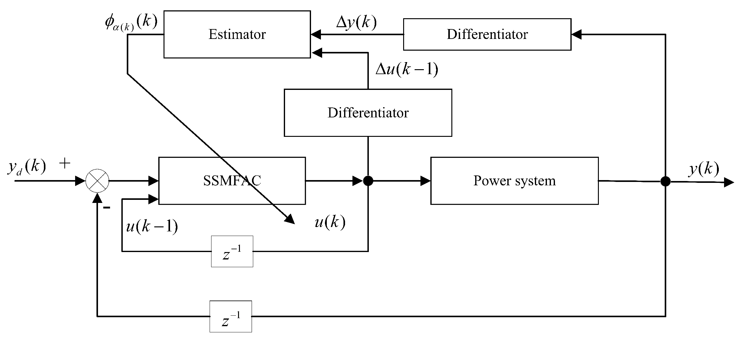
Figure 1. Block diagram of SSMFAC.
Algorithms 17 00233 g001
Figure 2. The curve of frequency deviation response.
Algorithms 17 00233 g002
Figure 3. The response curve of change in tie-line power.
Algorithms 17 00233 g003
Figure 4. The curve of A C E i .
Algorithms 17 00233 g004
Figure 5. Any 100 switching sequences in the system.
Algorithms 17 00233 g005
Figure 6. Event triggering intervals in area 1.
Algorithms 17 00233 g006
Figure 7. Event triggering intervals in area 2.
Algorithms 17 00233 g007
Figure 8. Event triggering intervals in area 3.
Algorithms 17 00233 g008
Figure 9. Comparison with PI controller.
Algorithms 17 00233 g009
Figure 10. Noise impact on system response.
Algorithms 17 00233 g010
Figure 11. Random loaddisturbances.
Algorithms 17 00233 g011
Figure 12. Frequency responses of the LFC scheme.
Algorithms 17 00233 g012
Table 1. Definition of related signals in region i.
SymbolicMeaning
Δ f i Frequency deviation ( Hz )
Δ P m i The amount of mechanical power variation in the generator ( pu )
Δ P g i The governor increases the power ( pu )
Δ P tie i The governor increases the power ( pu )
T g i Governor time constant ( s )
T i j Synchronous coefficient of tie line ( pu / Hz )
T t i Prime mover time constant ( s )
H i Equivalent inertia coefficient ( pu / s )
Δ P L i Load disturbance ( pu )
D i Equivalent damping coefficient ( pu / Hz )
R i Equivalent damping coefficient ( Hz / pu )
β i Frequency deviation factor ( pu / Hz )
Δ P c i Control input ( pu )
Table 2. Simulation parameters for the power system.
ParametersArea 1Area 2Area 3
D / ( pu / Hz ) 1.01.51.8
M / ( pu · s)101212
R / ( Hz / pu ) 0.050.050.05
T t / s0.300.170.20
T g / s0.3740.35
Table 3. Performance comparison.
Control ProgramIAEITAE
SSMFAC0.000148450.00078395
ET-SSMFAC0.000157340.00083537
PI0.000167960.0017093
Disclaimer/Publisher’s Note: The statements, opinions and data contained in all publications are solely those of the individual author(s) and contributor(s) and not of MDPI and/or the editor(s). MDPI and/or the editor(s) disclaim responsibility for any injury to people or property resulting from any ideas, methods, instructions or products referred to in the content.